
The heater parts need to be riveted after the parts are drilled.
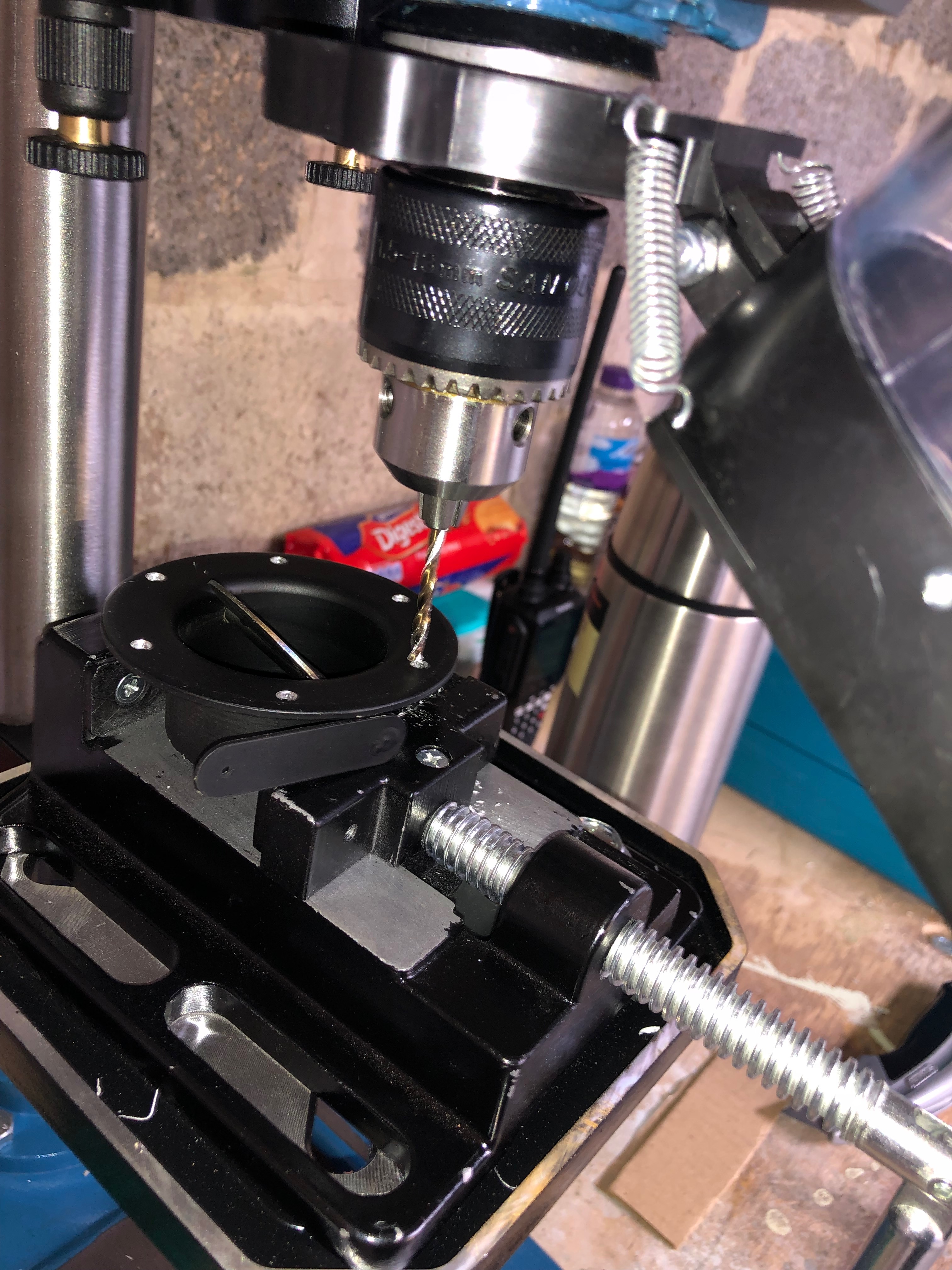
Once drilled the parts can be Cleco’d and riveted.
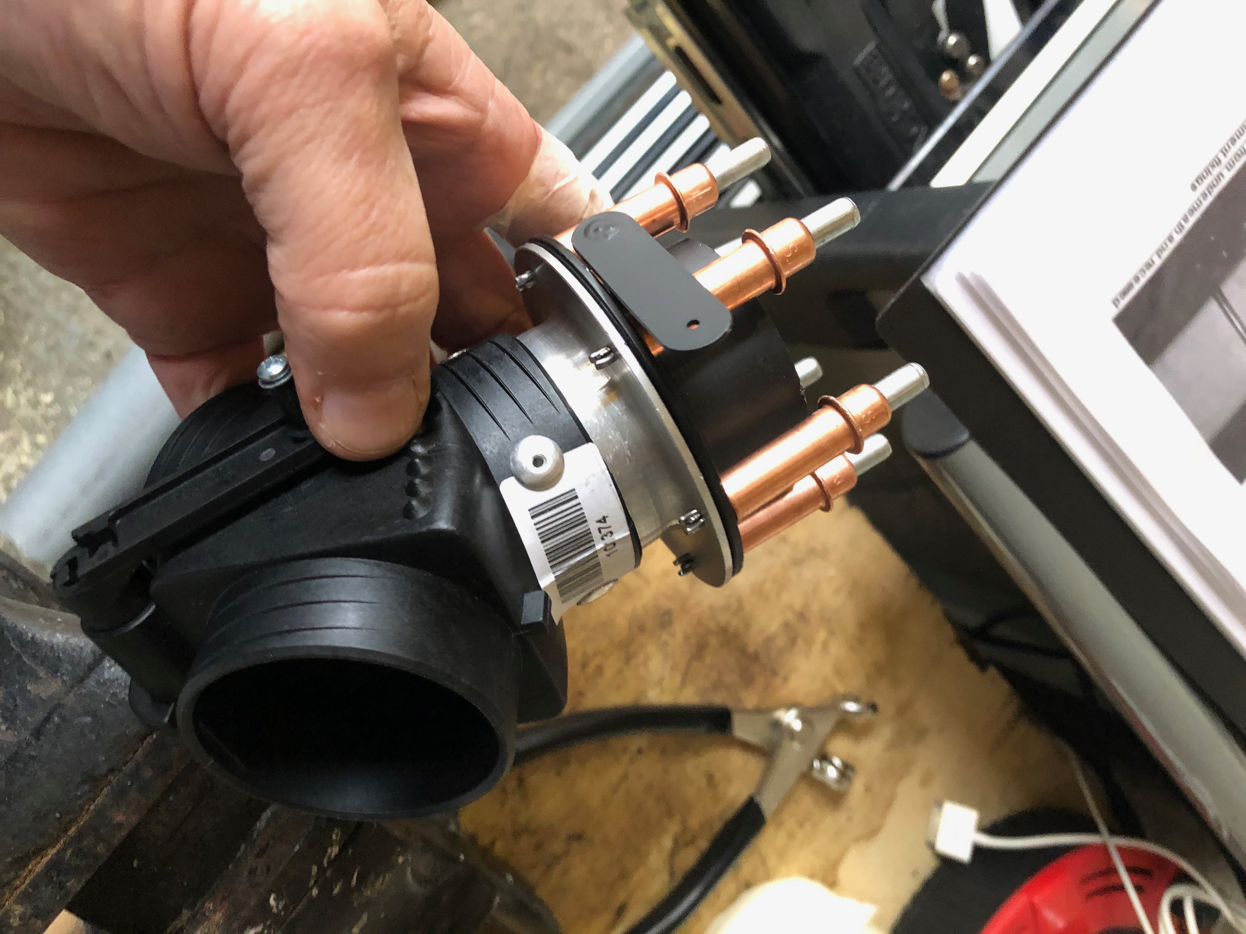
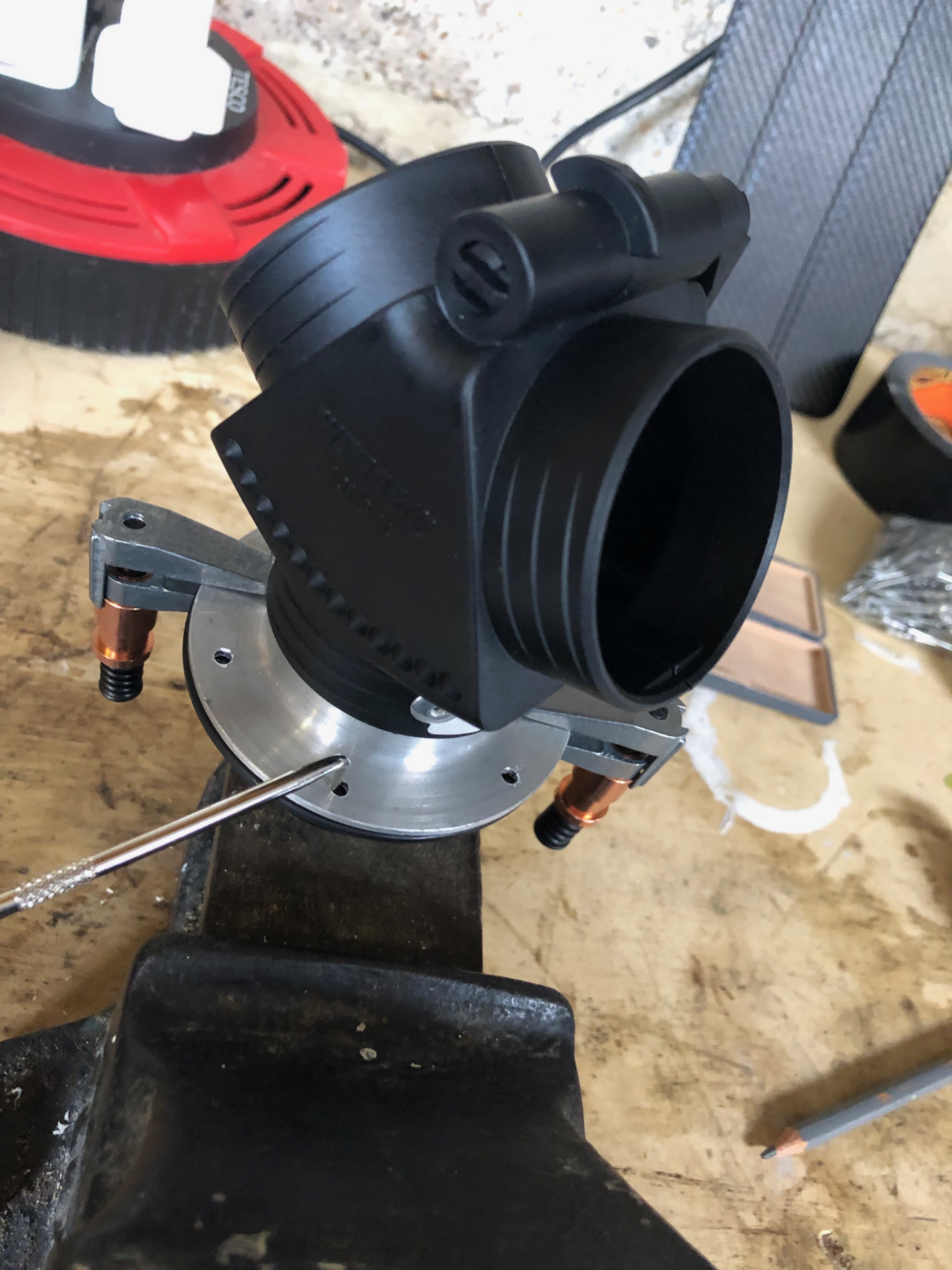
Test fit to ensure the holes are drilled correctly.
Some silicon sealer is applied before the footwell moulding is connected and riveted.

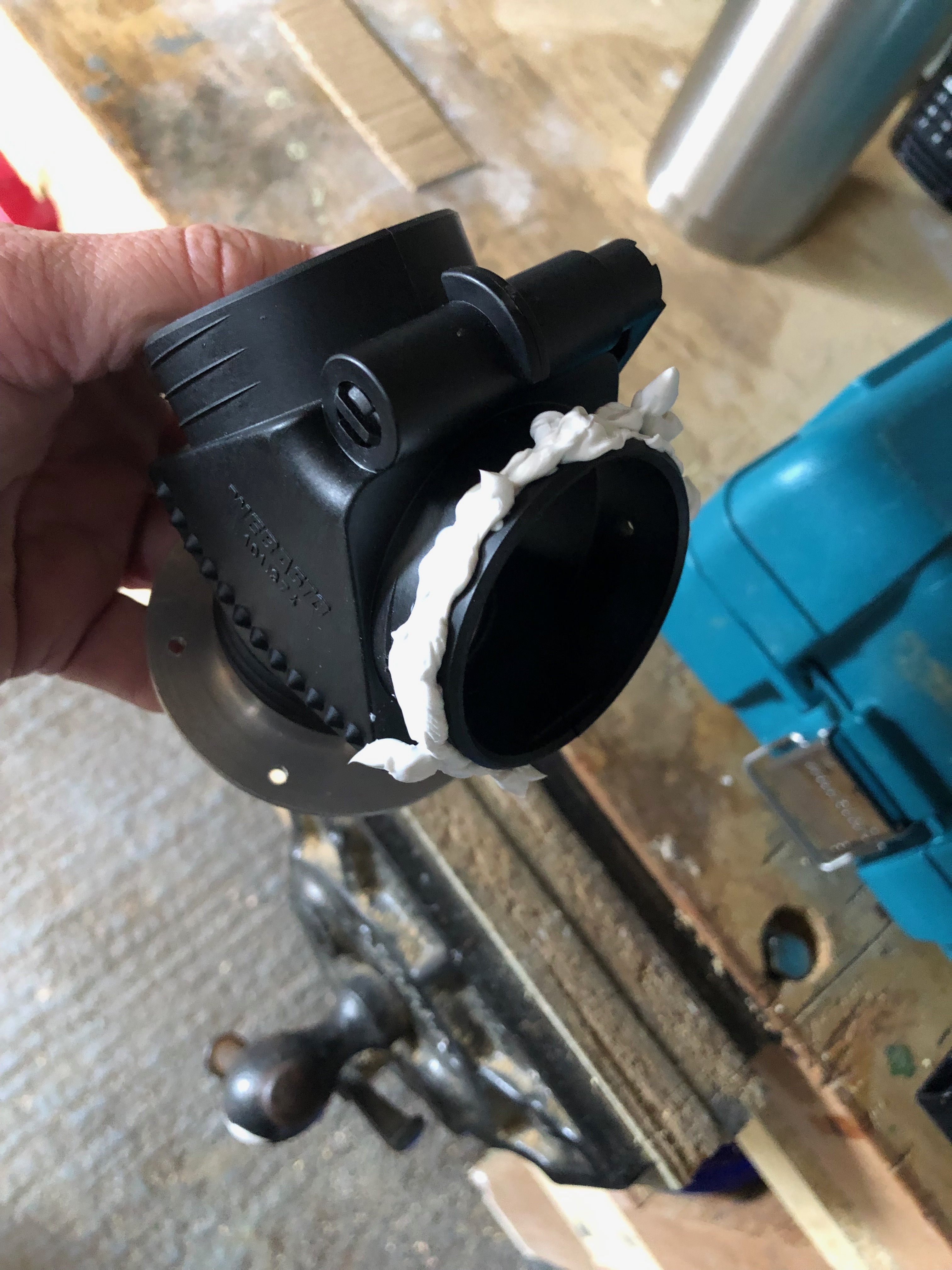
A bead of silicon is added to the heater valve before riveting.

The heater in situ.

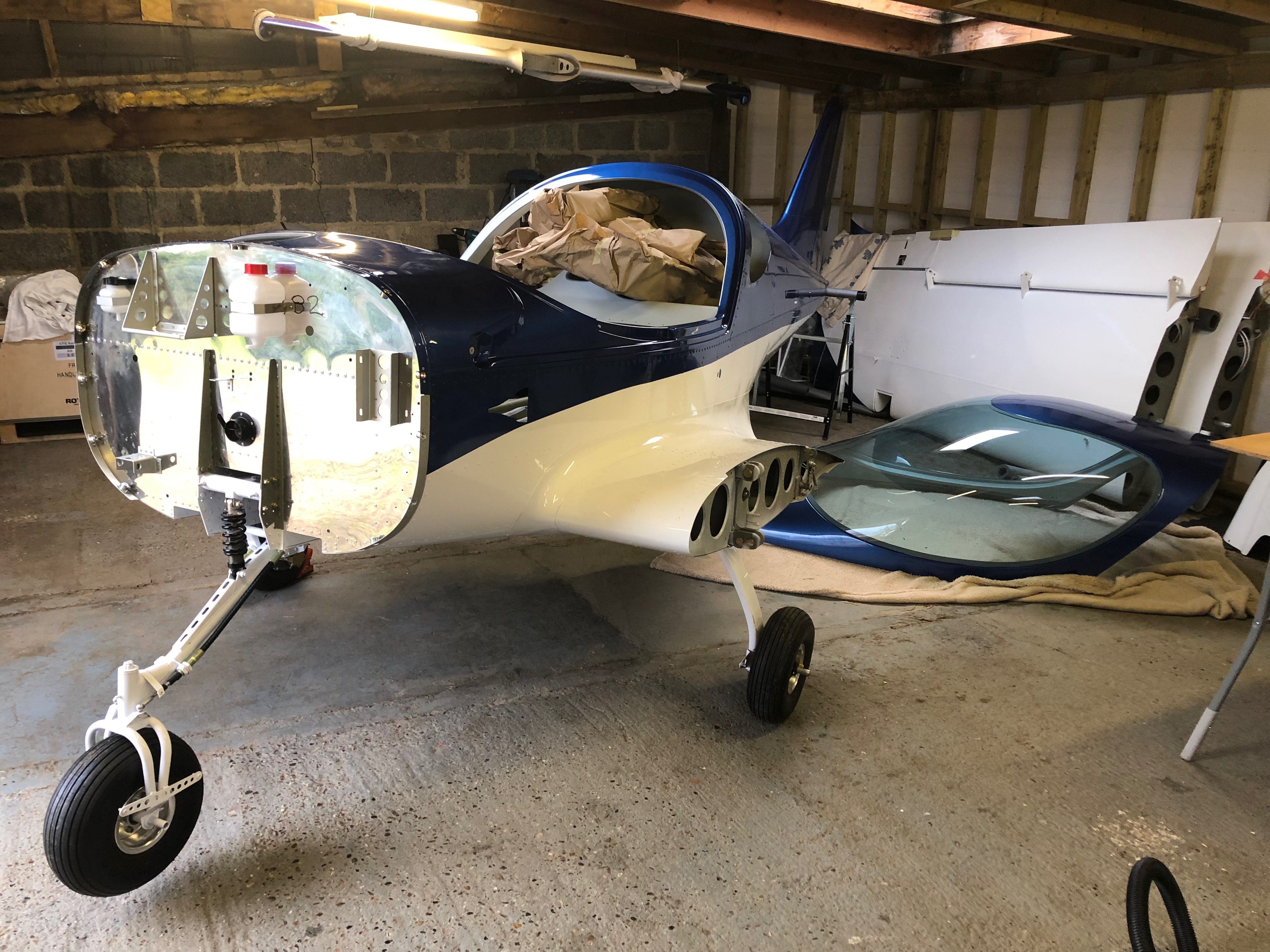
The firewall at the end of today.
First look of the Rotax 912 ULS 2. The water pump pipes need to be modified to enable the engine mount to be fitted after which it can be hung.

Lifting the lid of the box reveals lots of packing.
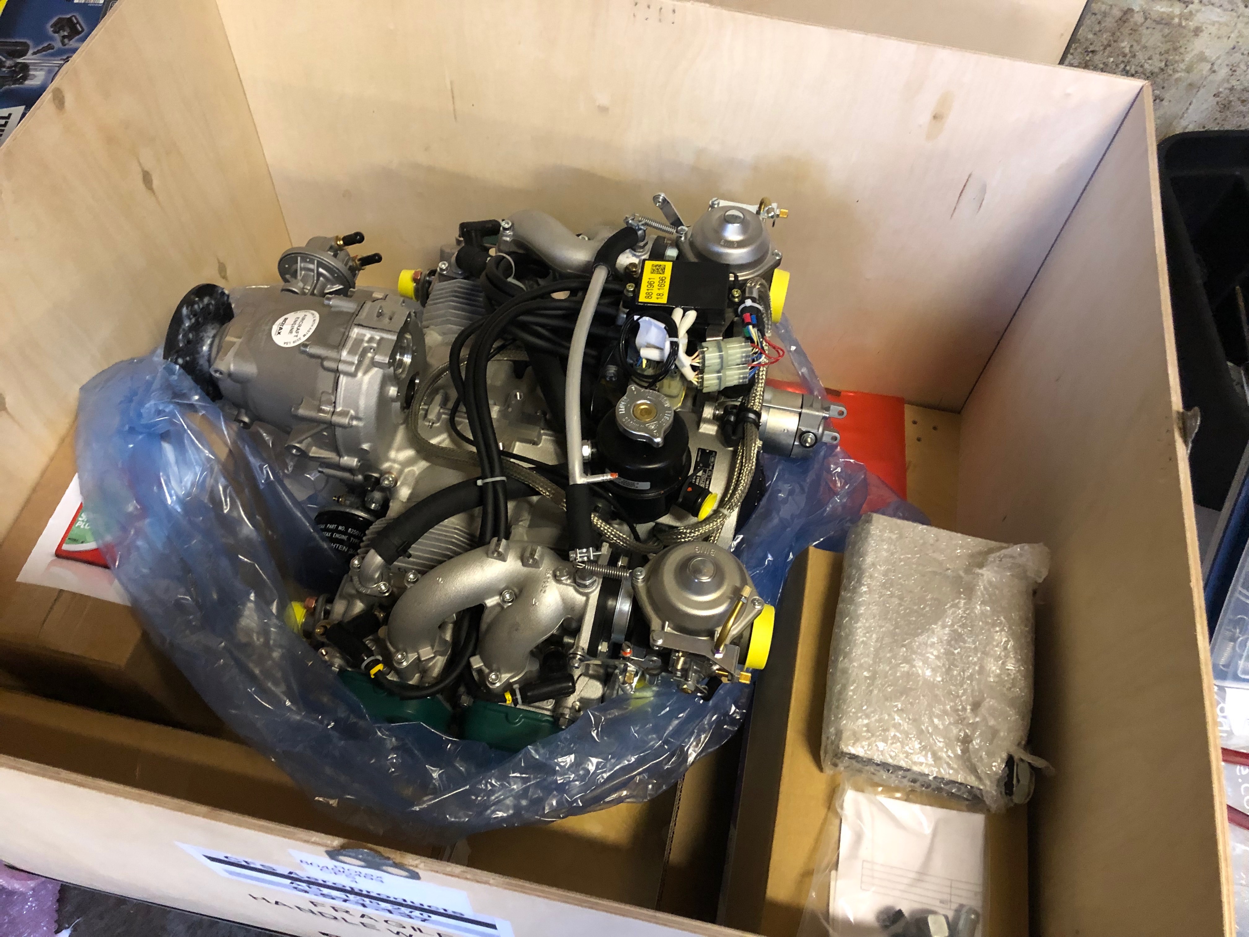
The Rotax 912 ULS 2 with ancillary parts.
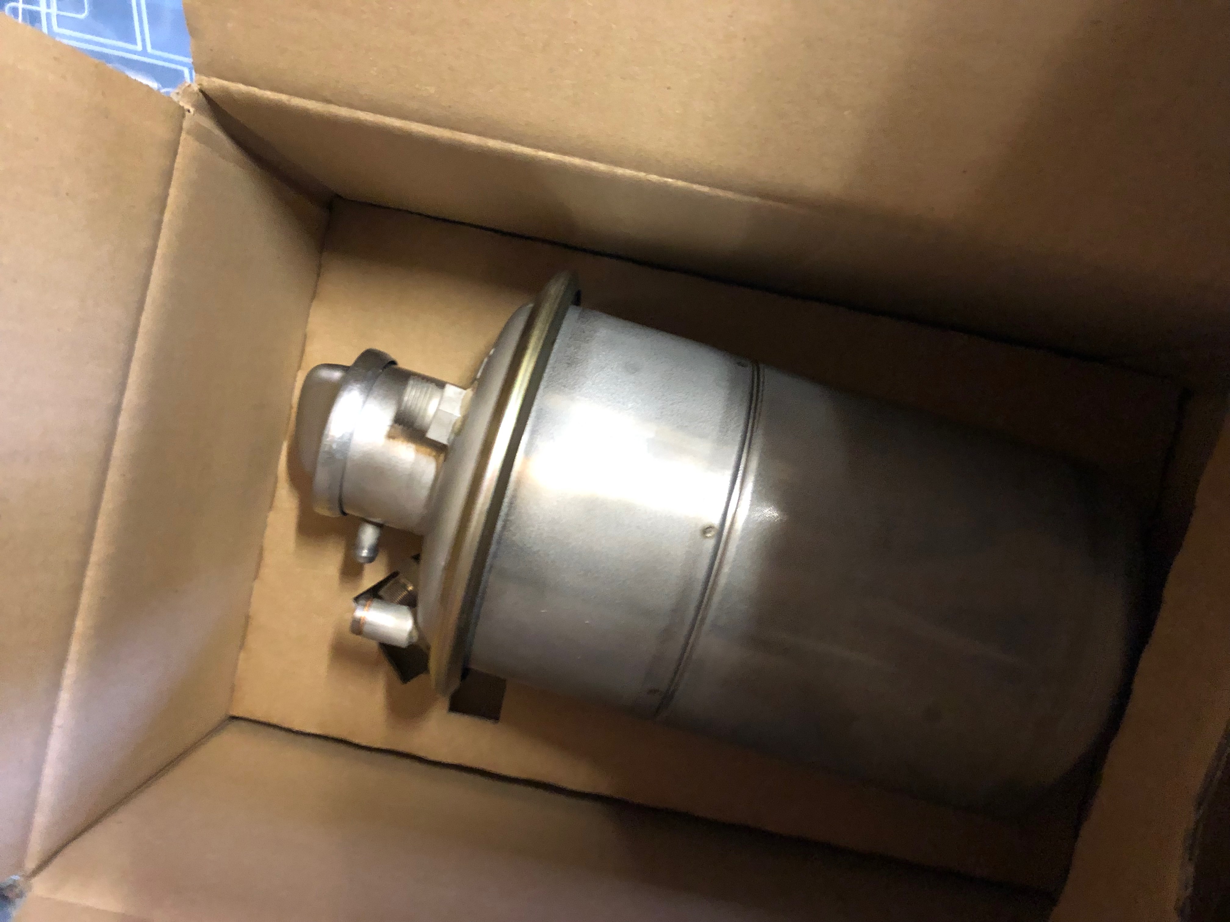
Oil tank.
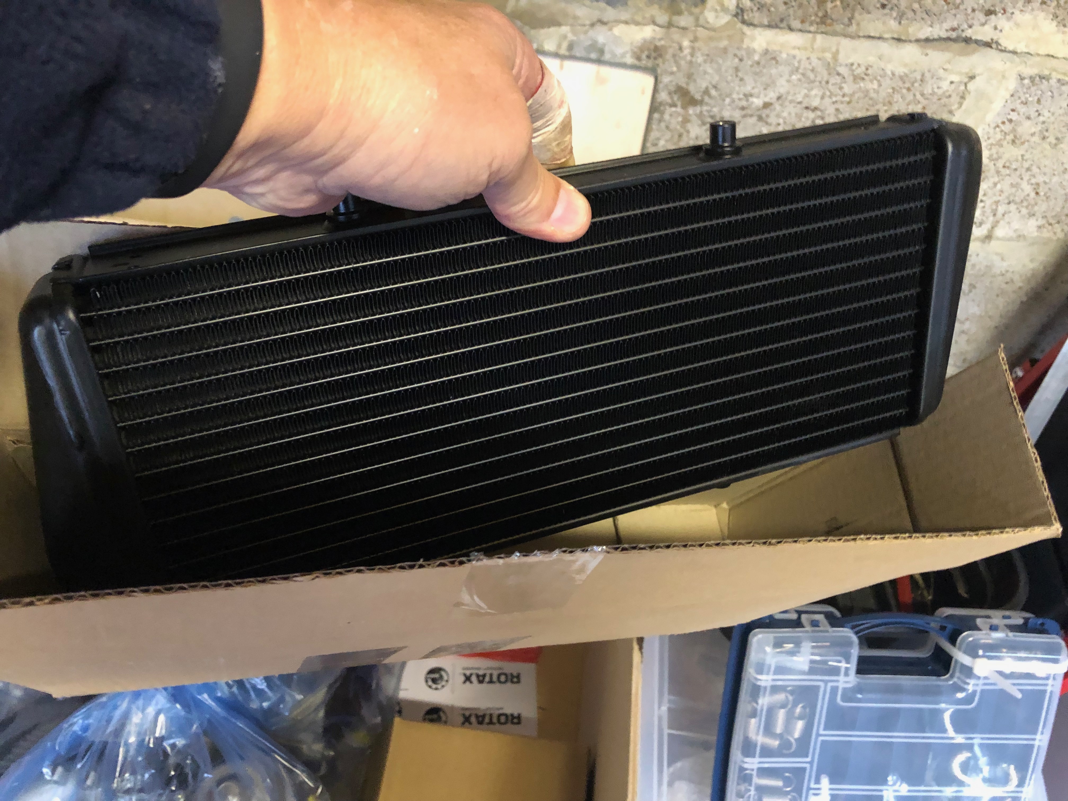
Oil radiator.
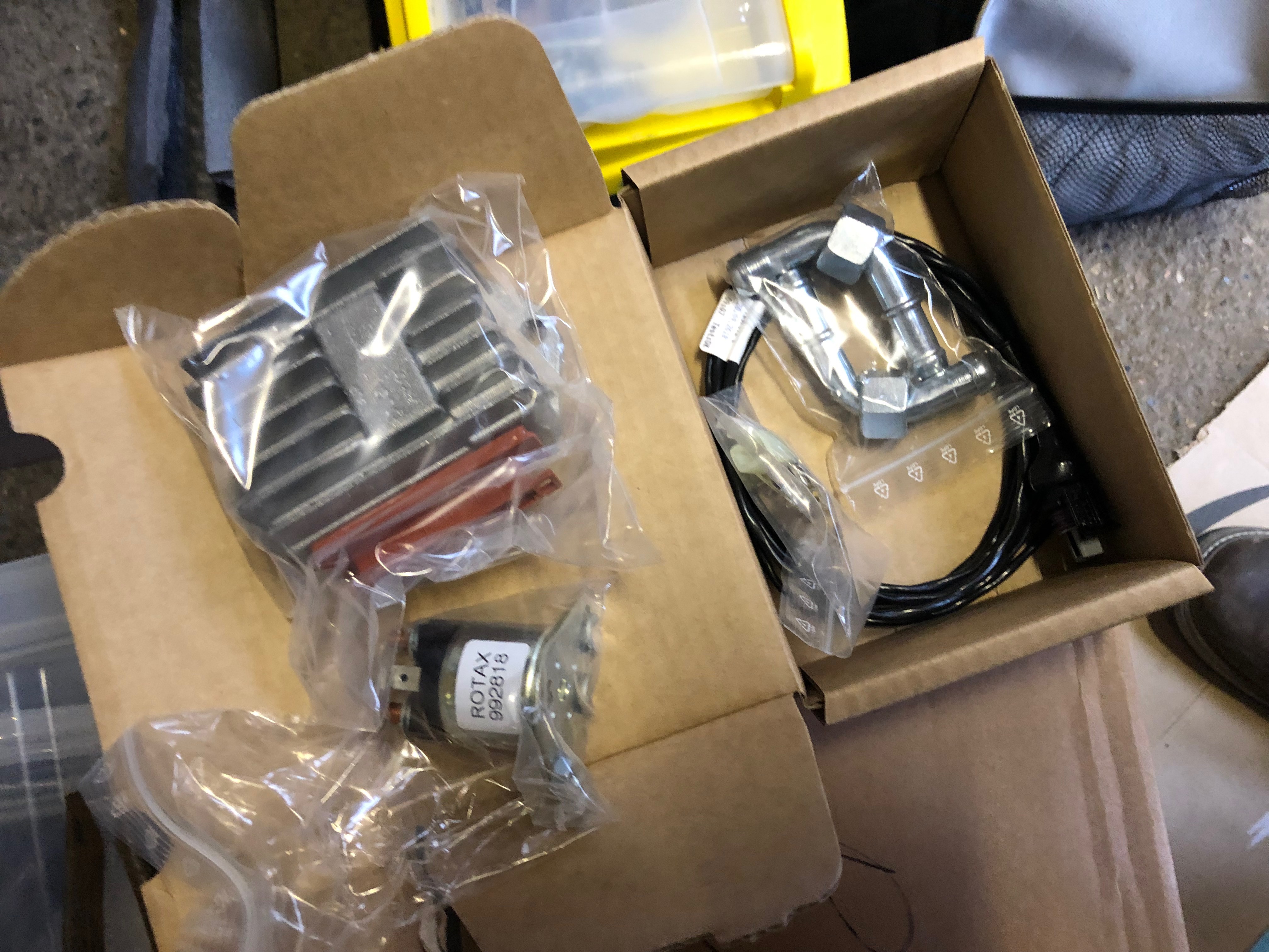
Regulator and starter solenoid and cabling with oil connectors in box below.

Water radiator connector pipes.

To enable work inside the cockpit the canopy needs to be removed.
Seems the best place to put it for the time being.

The interior moulding are moved to the rear shelf.
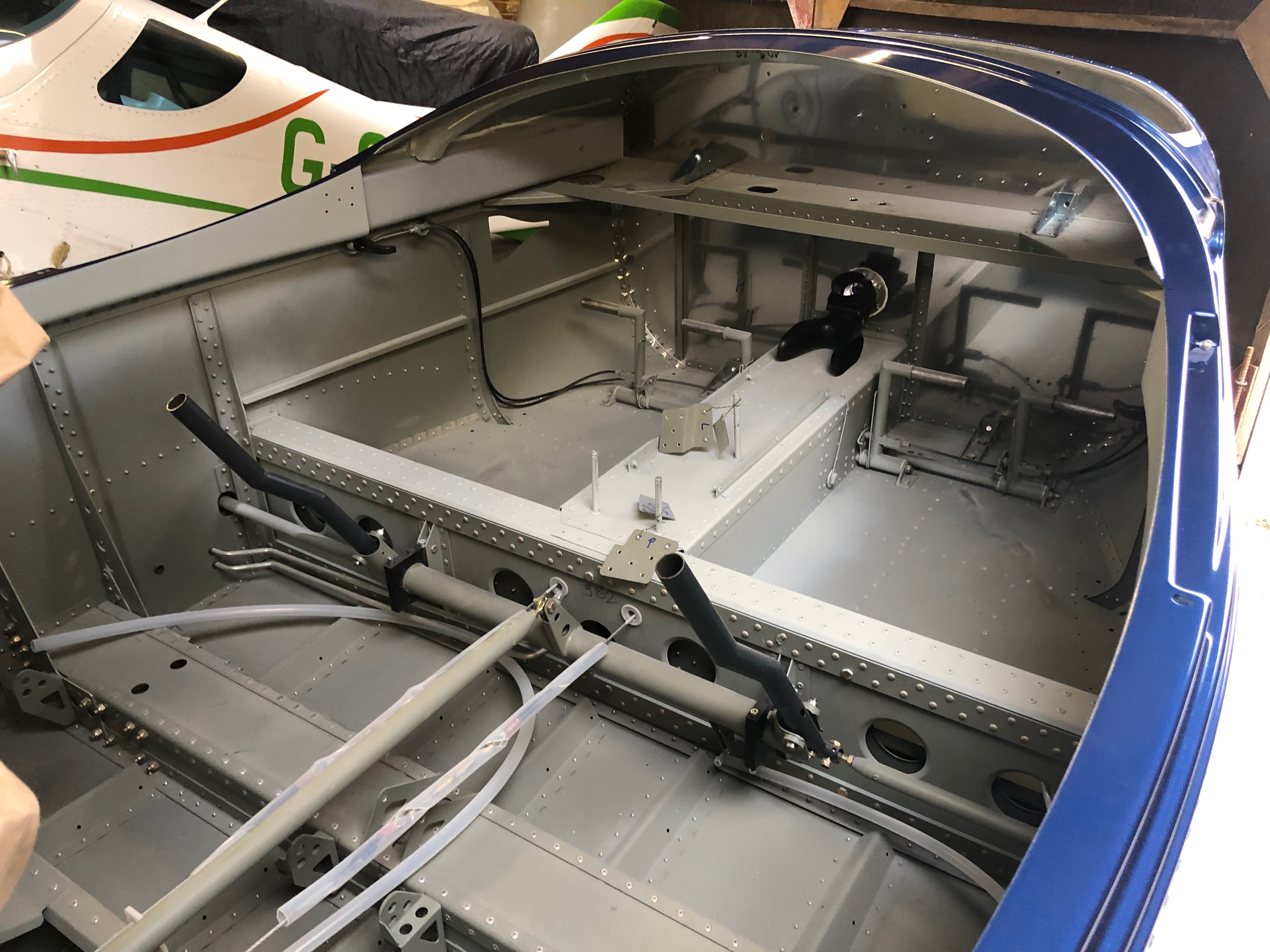
Giving a free cockpit area to work in.
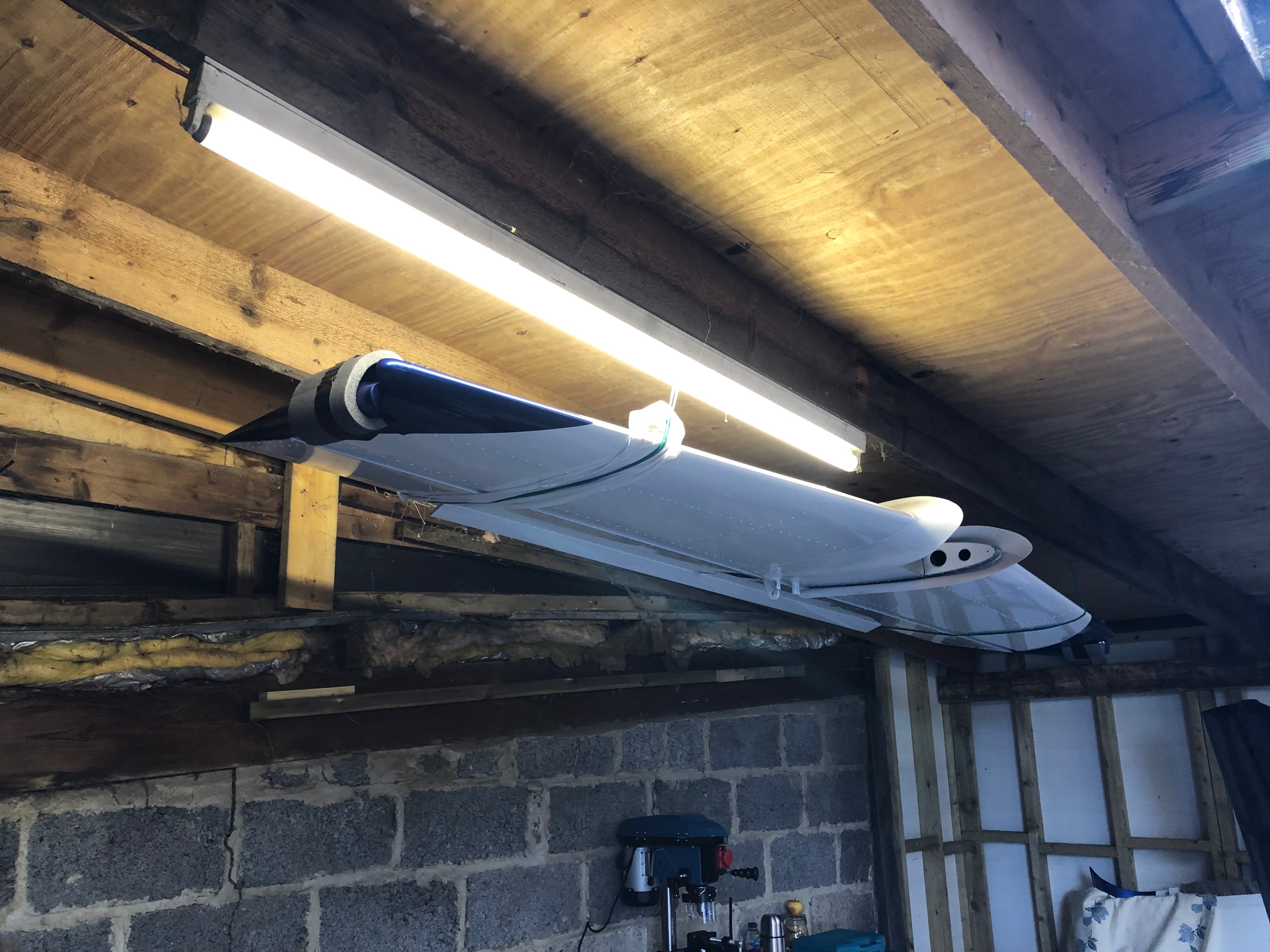
With the tailplane hung from the ceiling to give more working space in the workshop.
