Today I completed the installation of the right wing landing lights and strobe light and as it was quite warm today I decided to seal the canopy plexiglass with the silicone sealer.
The landing lights covers have to be a flush fit so countersunk M4 rivnuts are used to facilitate this.
When installing the rivnut it’s important to ensure that it’s not installed at an angle.
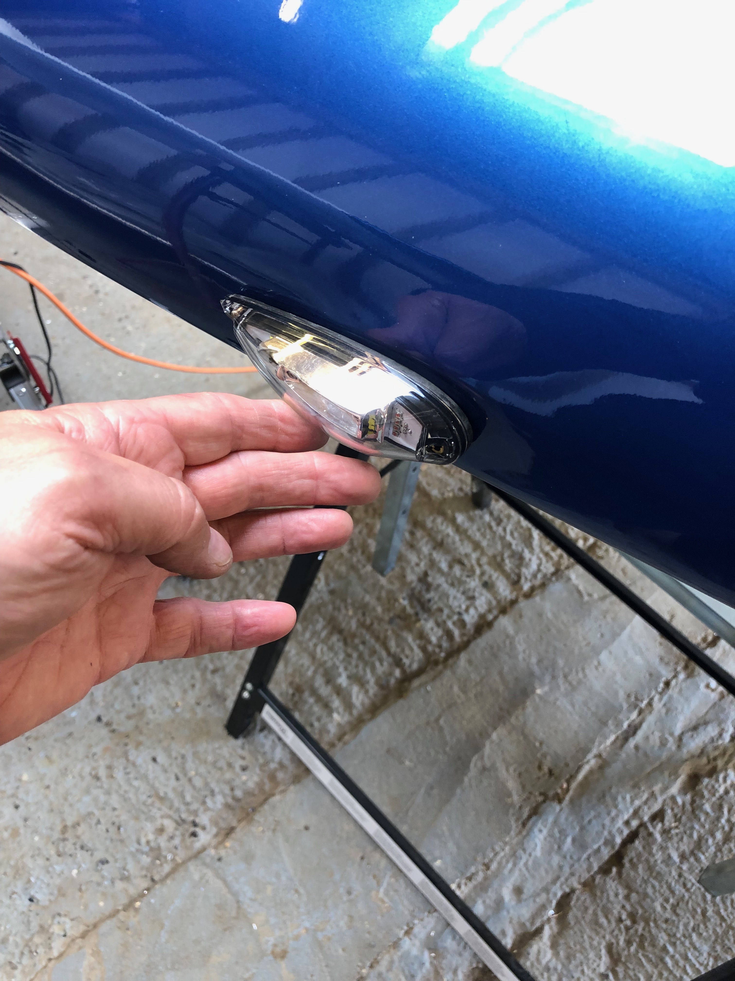
The starboard landing light and cover complete.
As it’s been a warm day I thought it would be a good time to seal the plexiglass. It has already had a first fit at the factory but needs sealing with silicone before it can be used in service.
The channel is filled in a similar way to sealing around a bath!
Once the channel is filled it needs to be smoothed. It’s suggested that the back of a spoon is used. If pressed hard enough it will leave two lines either side of the filled channel. This allows the waste material to be removed when it’s set in a couple of days.
The finished canopy. The waste material will be removed on Monday or Tuesday.
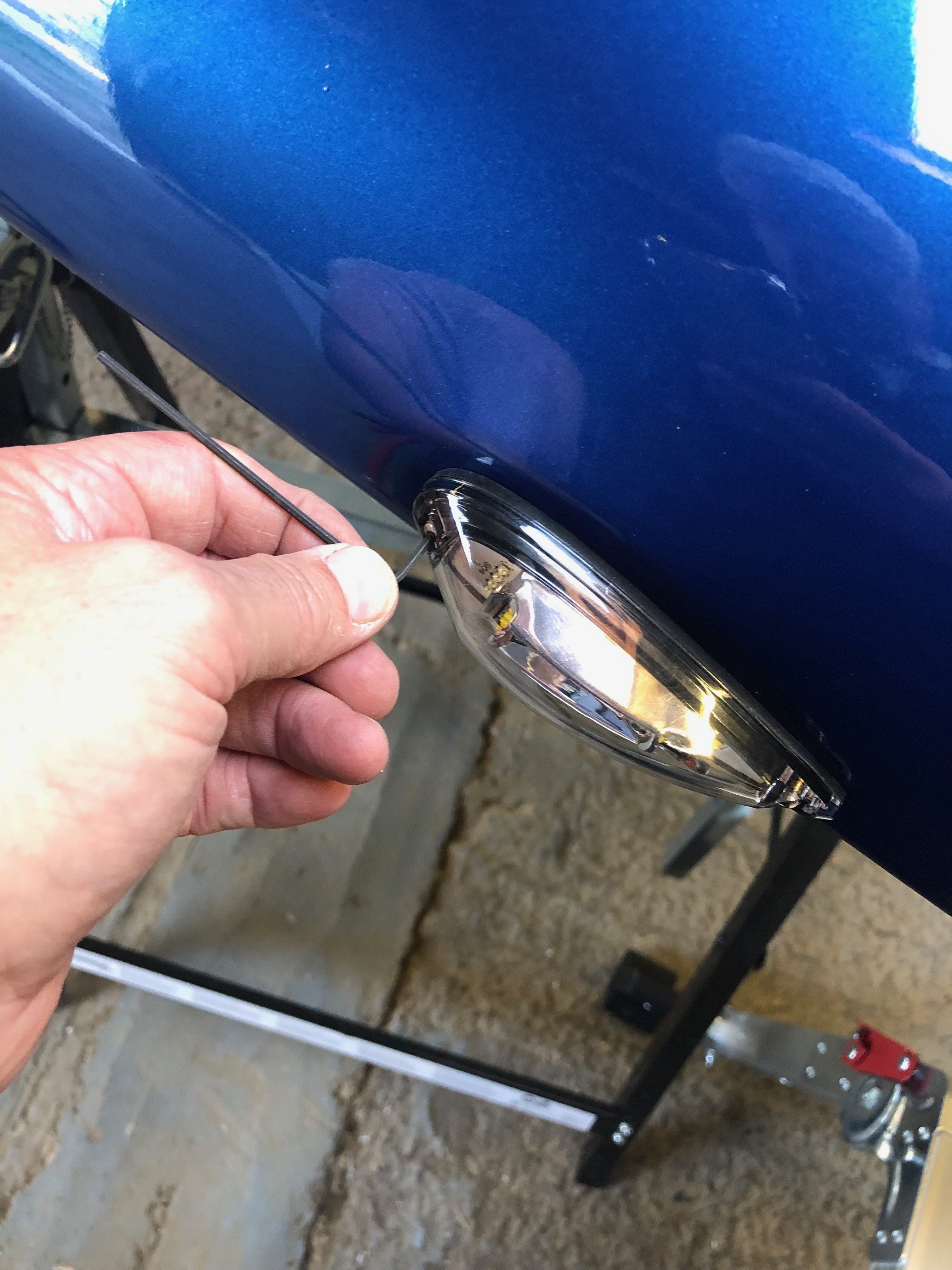
Next is to fit the starboard strobe. The cable need to be soldered and as with the port wing the wire colours are different so a record needs to be kept for the wiring records.
There is a flat section for the strobe but no definite location is marked so the strobe needs to be positioned to what looks ‘right’.
The holes are drilled and M3 countersunk rivnuts that I purchased this morning from DJ Invicta Supplies are installed and the light is secured with M3 stainless steel button head screws.
The starboard lights complete I’ll leave the wing on the stand ready to install the Pitot on Monday once I get the pitot mount from Farry.
Today was spent mainly wiring up the aileron trim motor, installing the port strobe before starting on the starboard wing landing light.
One little job to do today was to install an overflow pipe from the water expansion tank to the water bottle mounted on the firewall.
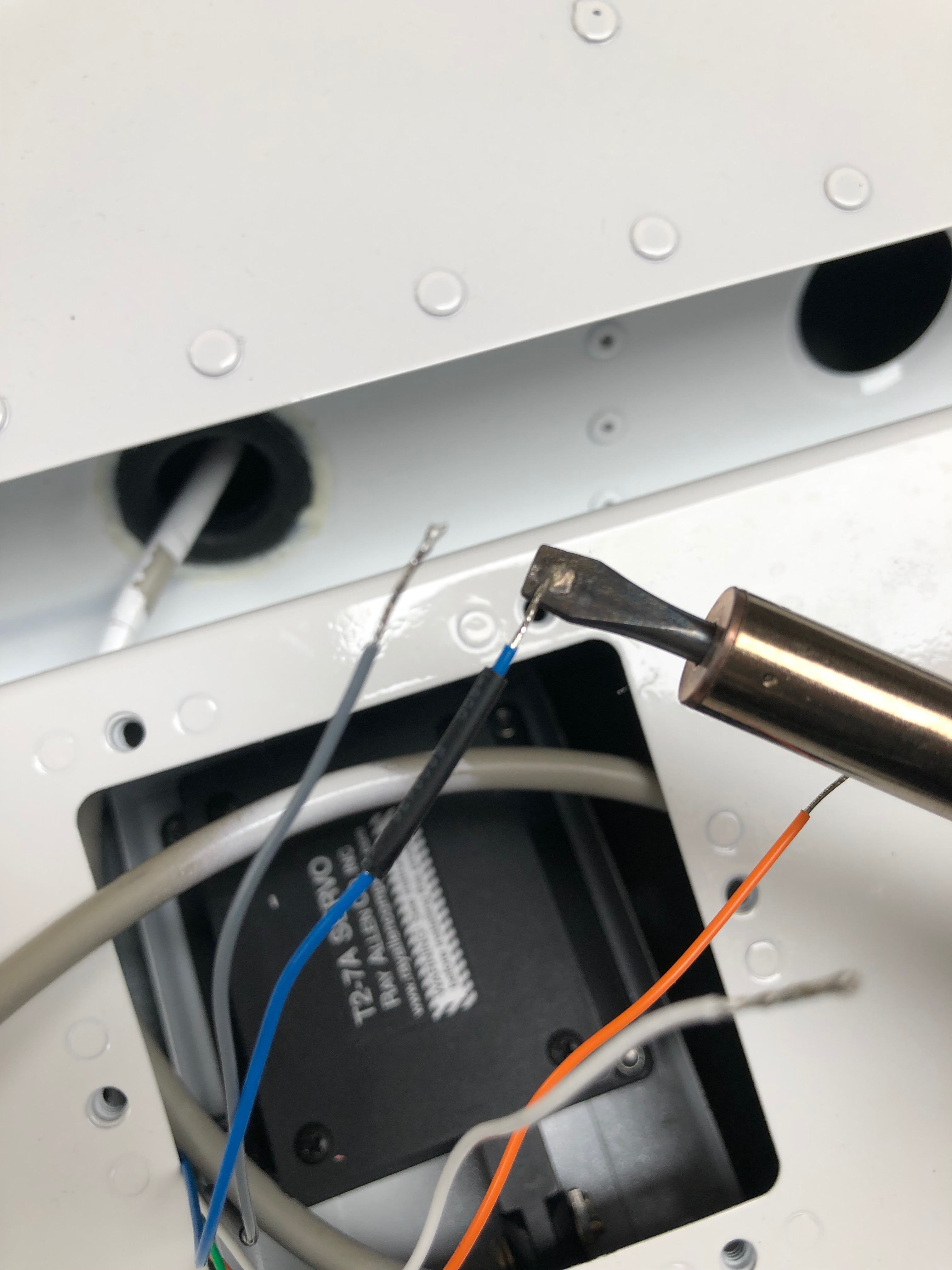
The aileron trim motor is connected to the wire installed in the wing. The ends are stripped and tinned.
Heat shrink tube is slid onto the wires before the soldering is done to make sure that they are well insulated.
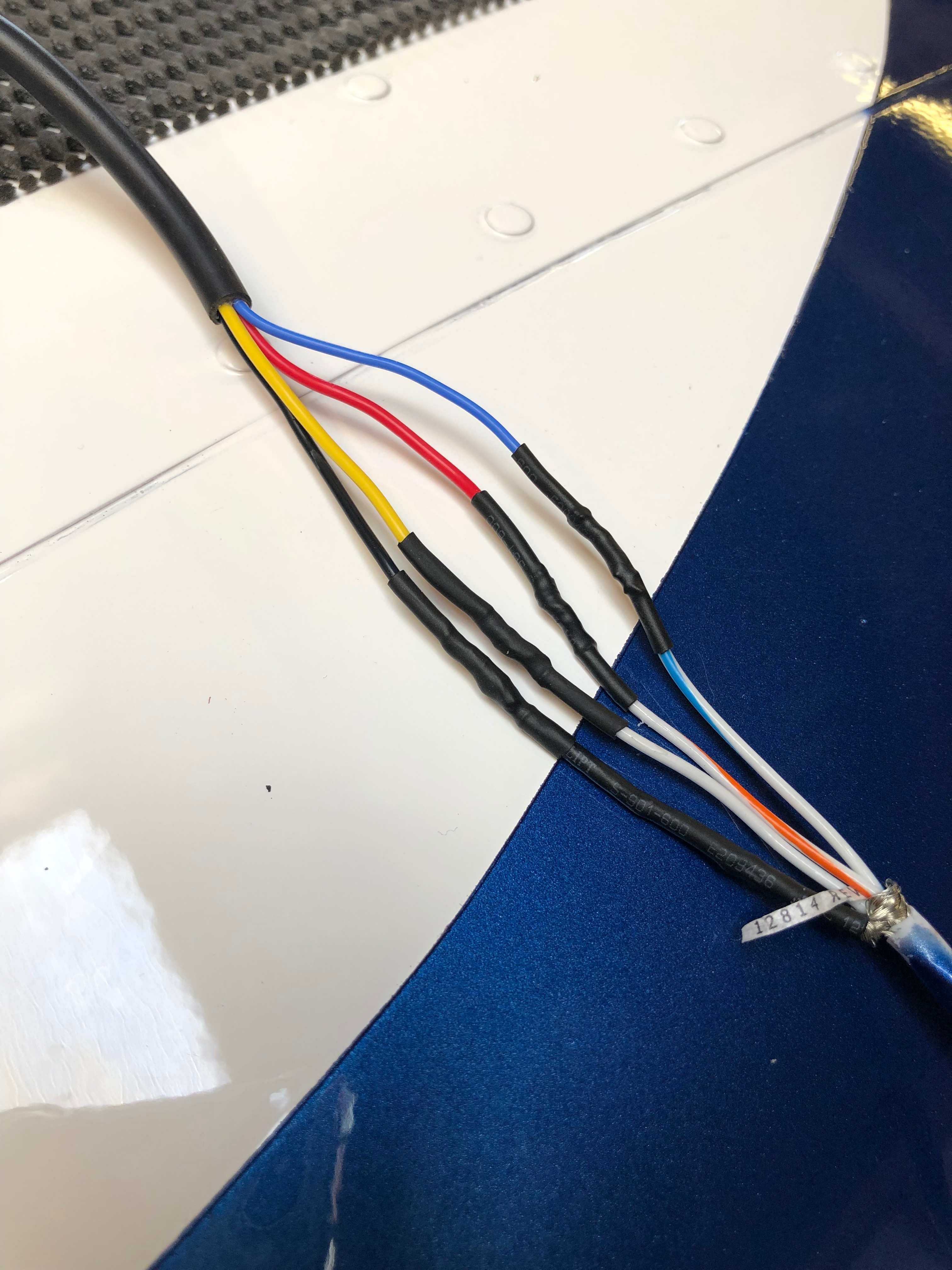
The colours don’t match between the trim motor and the wing wire so that will have to be documented in the aircraft wiring diagram.
A heat gun is used to shrink the tube over the wires and then a bigger piece (yellow tubing in picture) is slid over all the connections.
The wire is kept in place to stop it moving in operation with a spot of glue.
The strobes are next . Very important to mount the correct one on the correct side. Red is being installed on the left wing.
The same method is used to solder and secure the wire joints.
The strobe position is not marked so it’s important to get the right angle. I haven’t got any M3 rivnuts so will have to get some and do this tomorrow.
So the right wing is put on stands and I can now start on the landing lights and strobes for this wing. The pitot/AOA probe is installed on this wing but I don’t have the mount as it’s with Farry. So a 5 hour trip is required on Monday to get that and the most of the rest of the outstanding items.
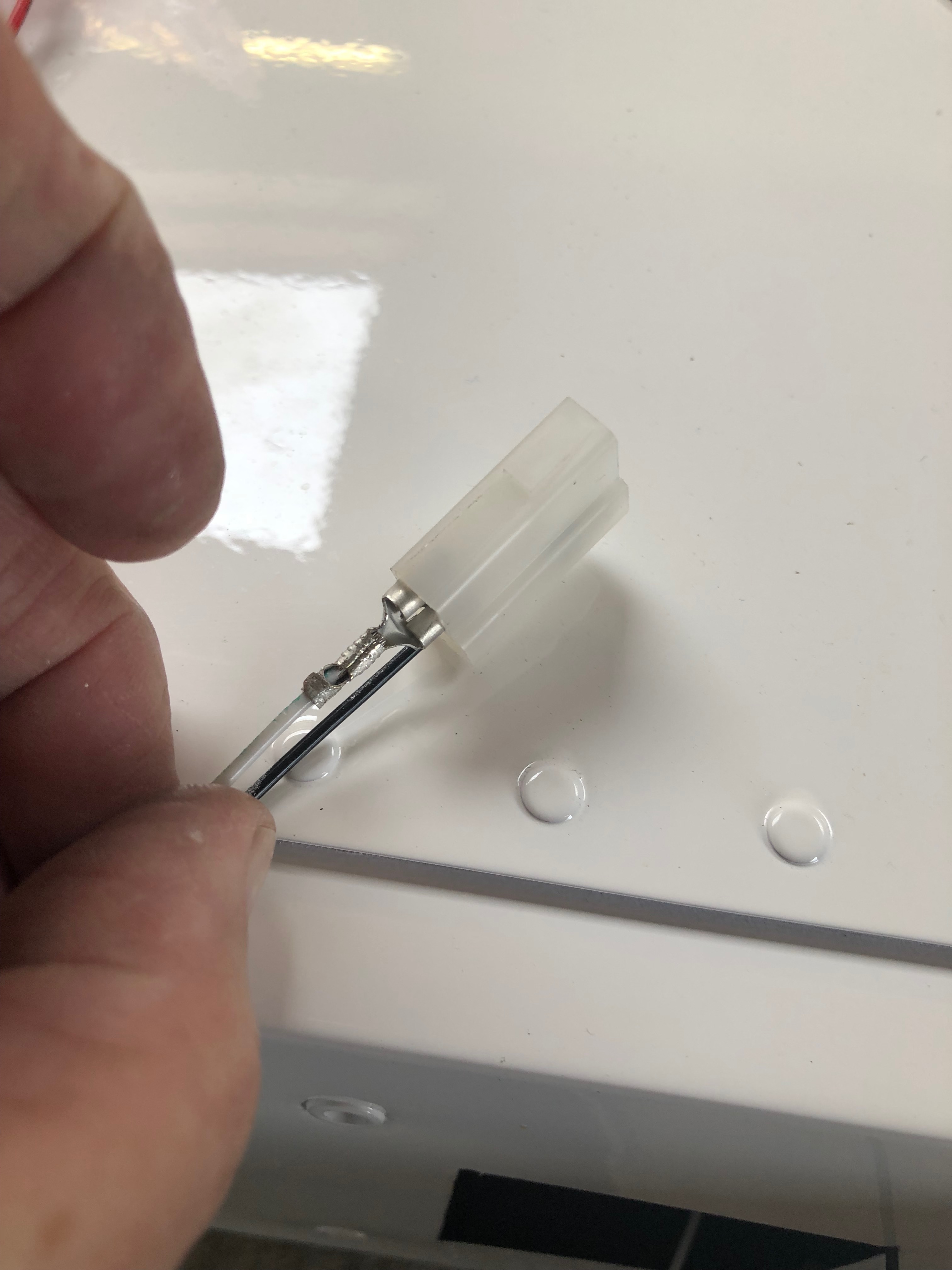
The spade connectors are crimped and inserted into the connector block.
The landing light is installed. It’s upside down as the wing is upside down!
The installed landing light ready for the cover which I’ll do tomorrow now as I’ve run out of time.
Finishing off the panel modification today and the start of the landing lights.
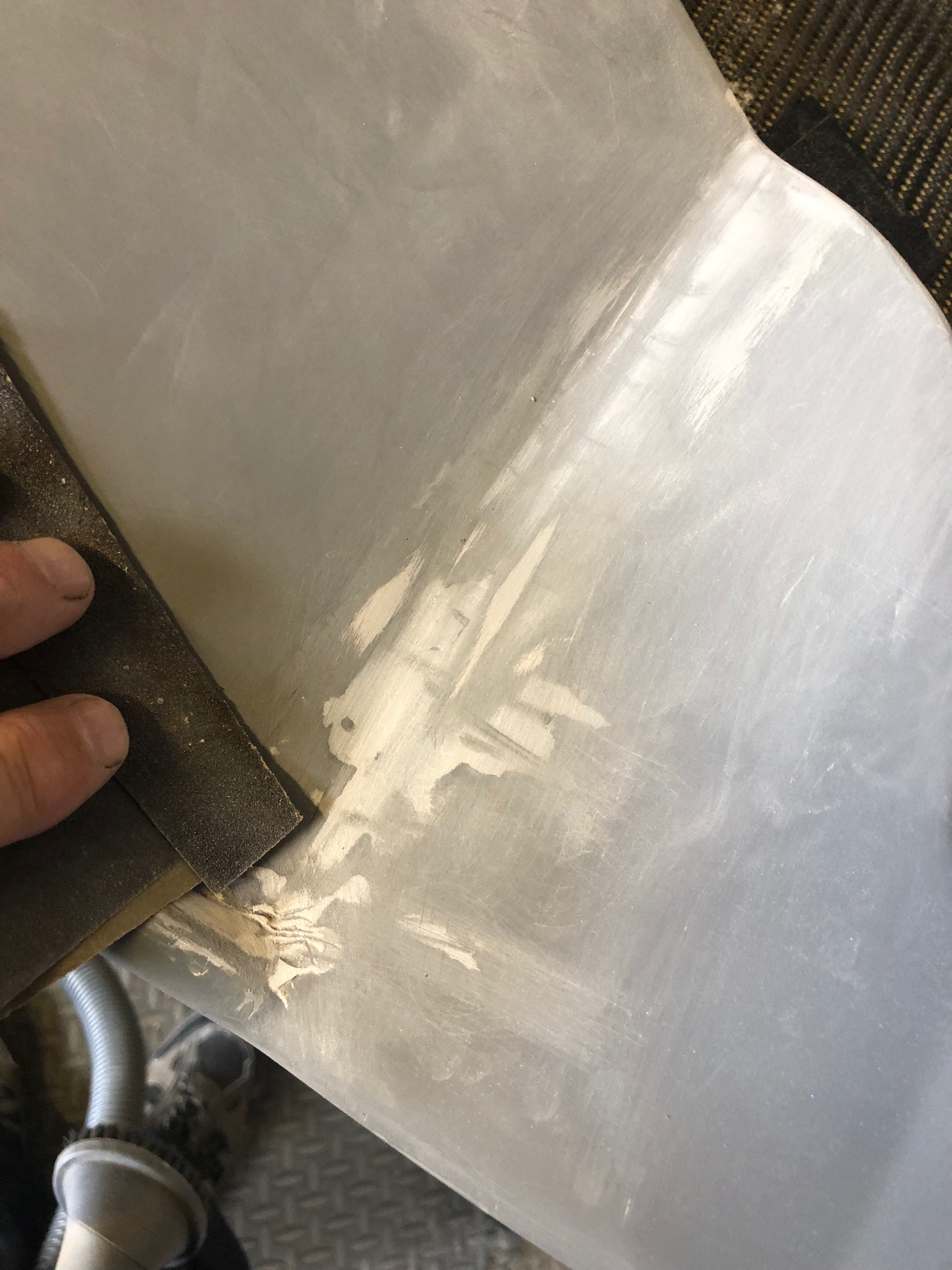
There were a couple of areas where I needed to use filler and then sand with fine wet & dry.
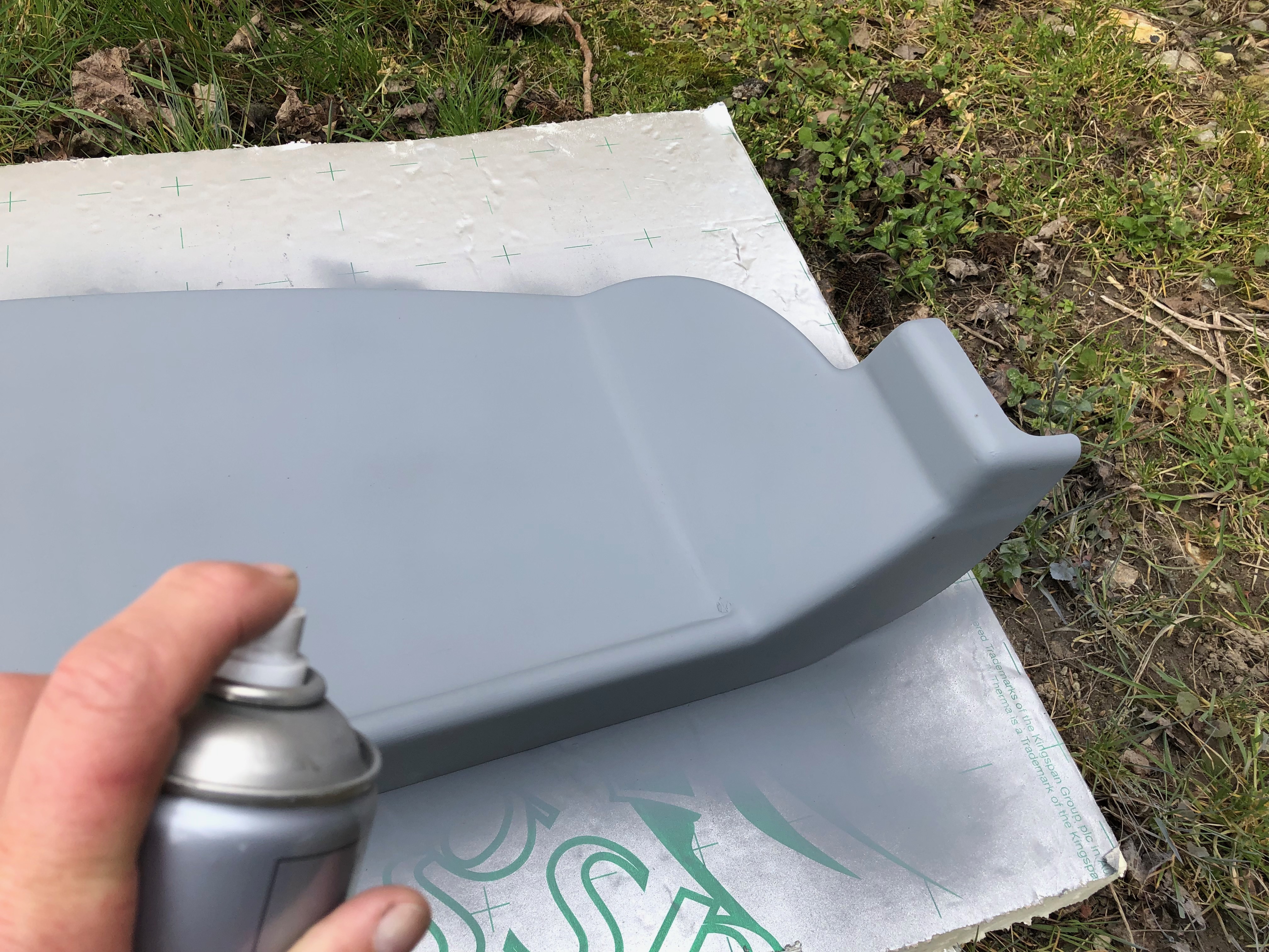
Primer is applied and is ready for painting.
Ian was back today after a few days away and gave me a hand to get a wing up on the stands so I can install the landing lights, wire the trim motor and fit the strobes.
The LED units are installed in both wings.
The wires are shortened and connectors are crimped and inserted into the connector block.
The unit is secured into place with M4 screws and then checked to ensure they work!
The light cover is secured into position with tape…
and six holes for the M4 countersunk rivnuts are drilled…
and countersunk. The rivnuts are then installed…
and the light cover is fitted and secured into place with countersunk stainless steel screws.
The interesting thing about building this aircraft is the number of activities and installations that need to be done that I’ve never done before. It takes a little thought to work out how to approach the task before starting but once completed successfully it gives you a great sense of achievement and satisfaction. The modification of the panel using glass fibre matting and resin is one such job. I knew what I wanted to achieve and now it’s complete I’m really pleased with the result.
This was how I left the panel yesterday. Now fully cured the fibreglass needs to be built up.
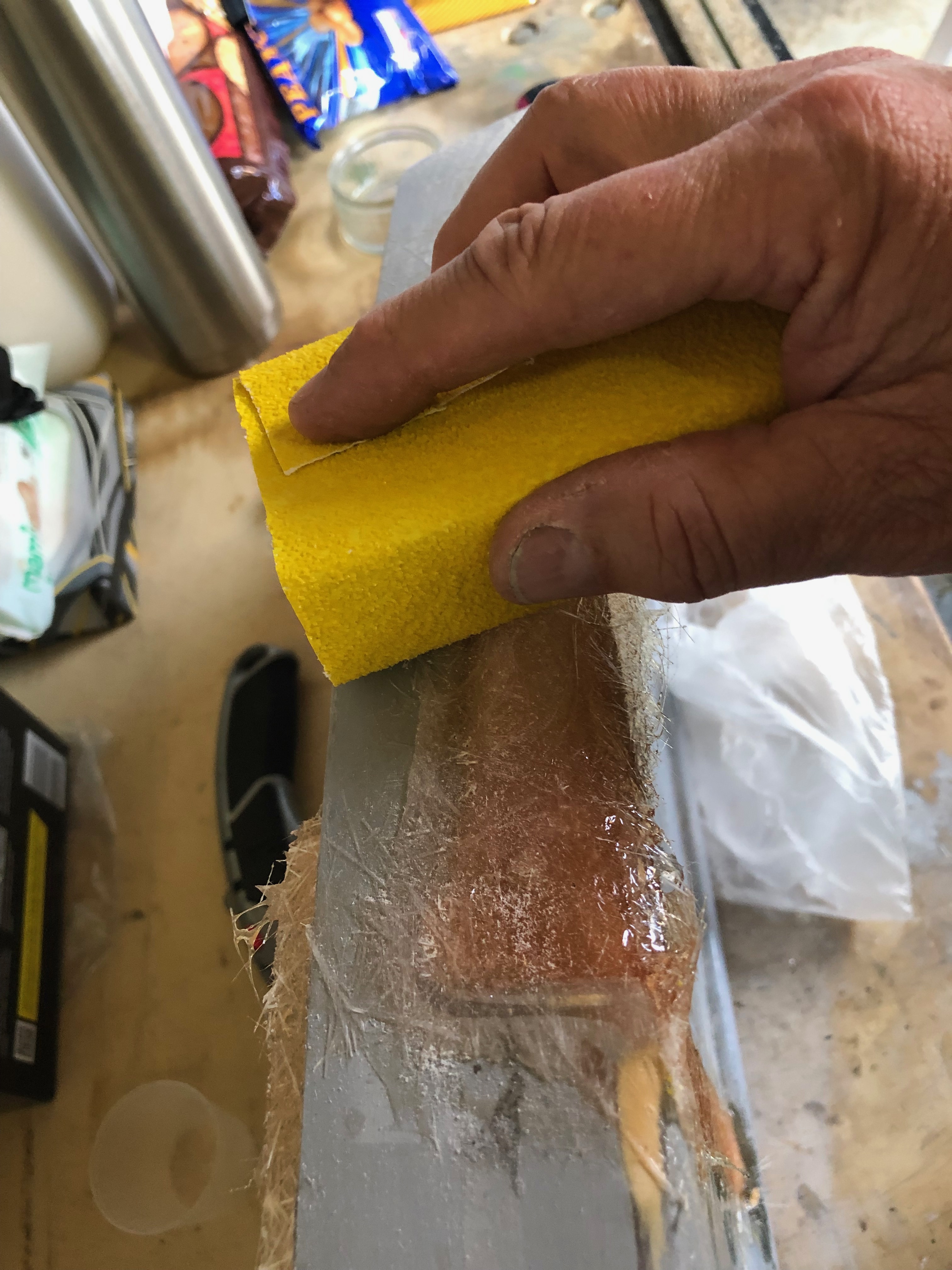
The area to be built up is wetted with resin and a layer of glass fibre is added and coated.
Once dried in around 30 minutes the area can be sanded down.
The rear of the panel ready is now complete but the front face needs to be filled with P38.
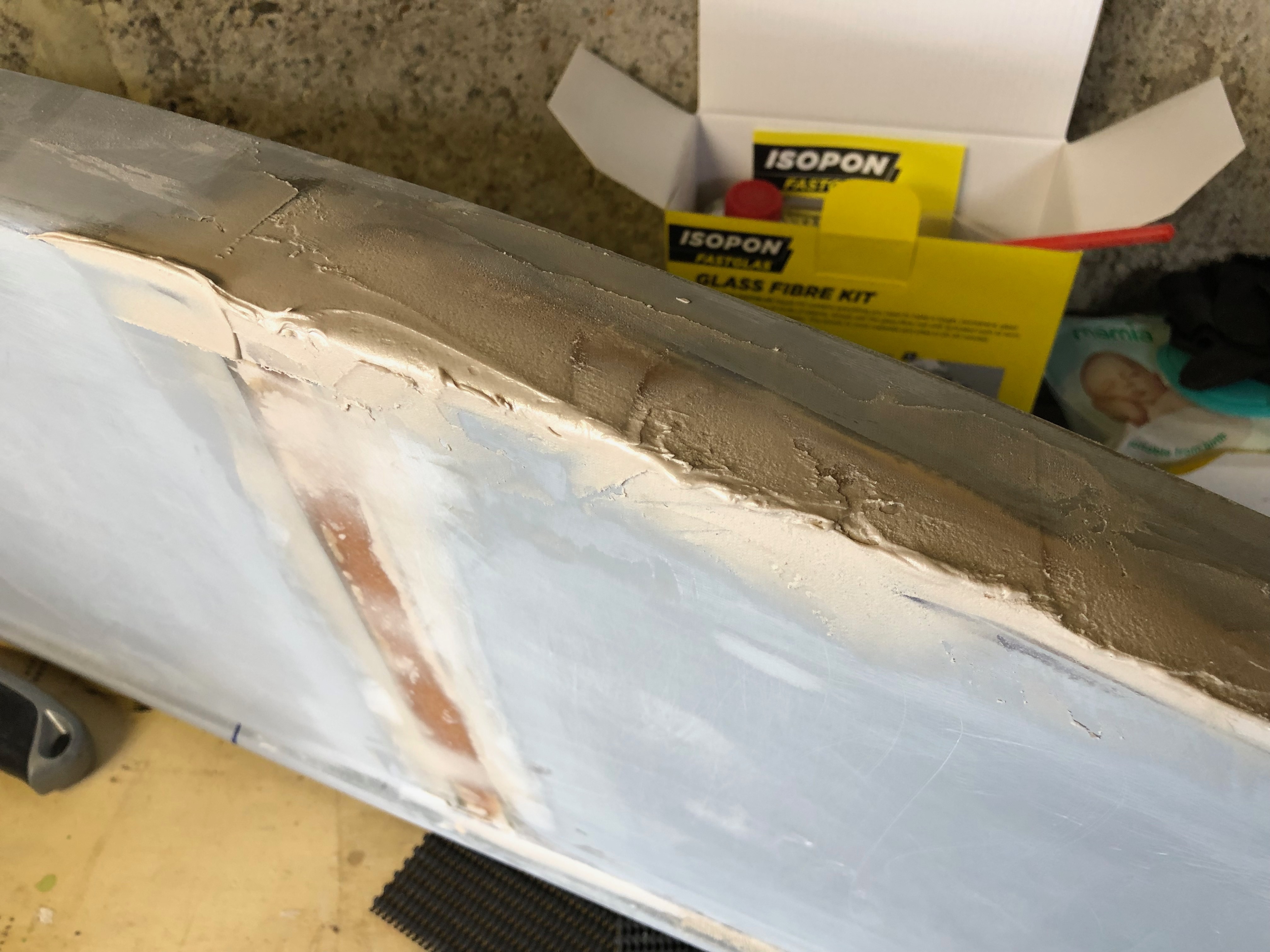
I used an Isopon glass fibre kit to bridge the gap and support the joins and P38 to fill and finish before painting with primer.
The filler is mixed using one golf ball sized ball of resin to one pea sized ball of hardener and mixed within 4 minutes. P38 sets in 20 minutes so you can’t hang around.
The filler is applied using a spatula and sanded smooth using 180 wet and dry. The process is repeated several times to remove any holes or dips.
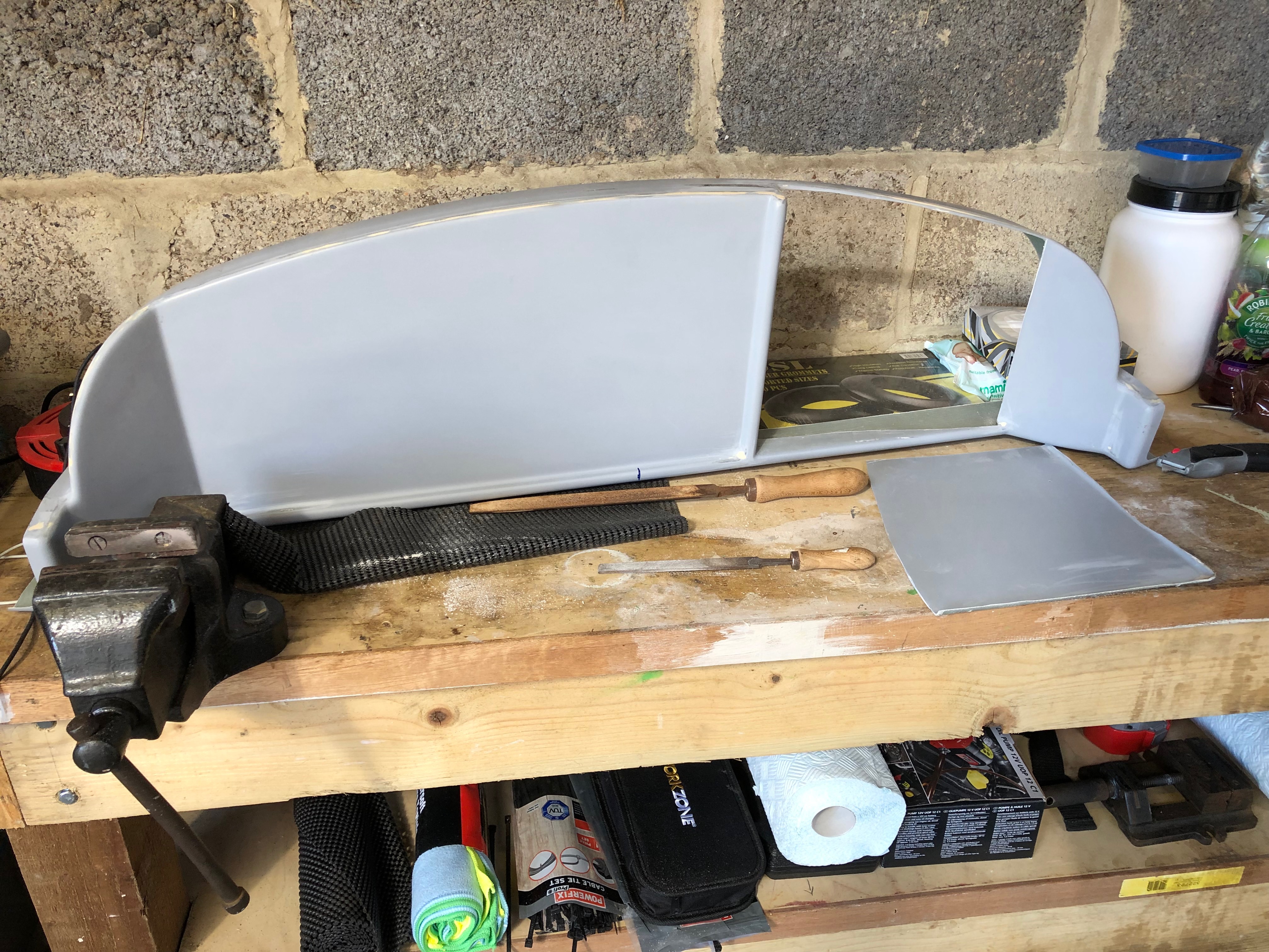
The finished panel prior to painting. Apart from the different colour where the join is you can’t tell that it’s been modified. Very pleased with the result!
The panel supplied with the Bristell kit has a recess on the righthand side that is slightly angled towards the pilot. Although it could be useful it restricts the flexibility of the instrument layout. I decided very early on that I would cut the recess out and make the panel flat.
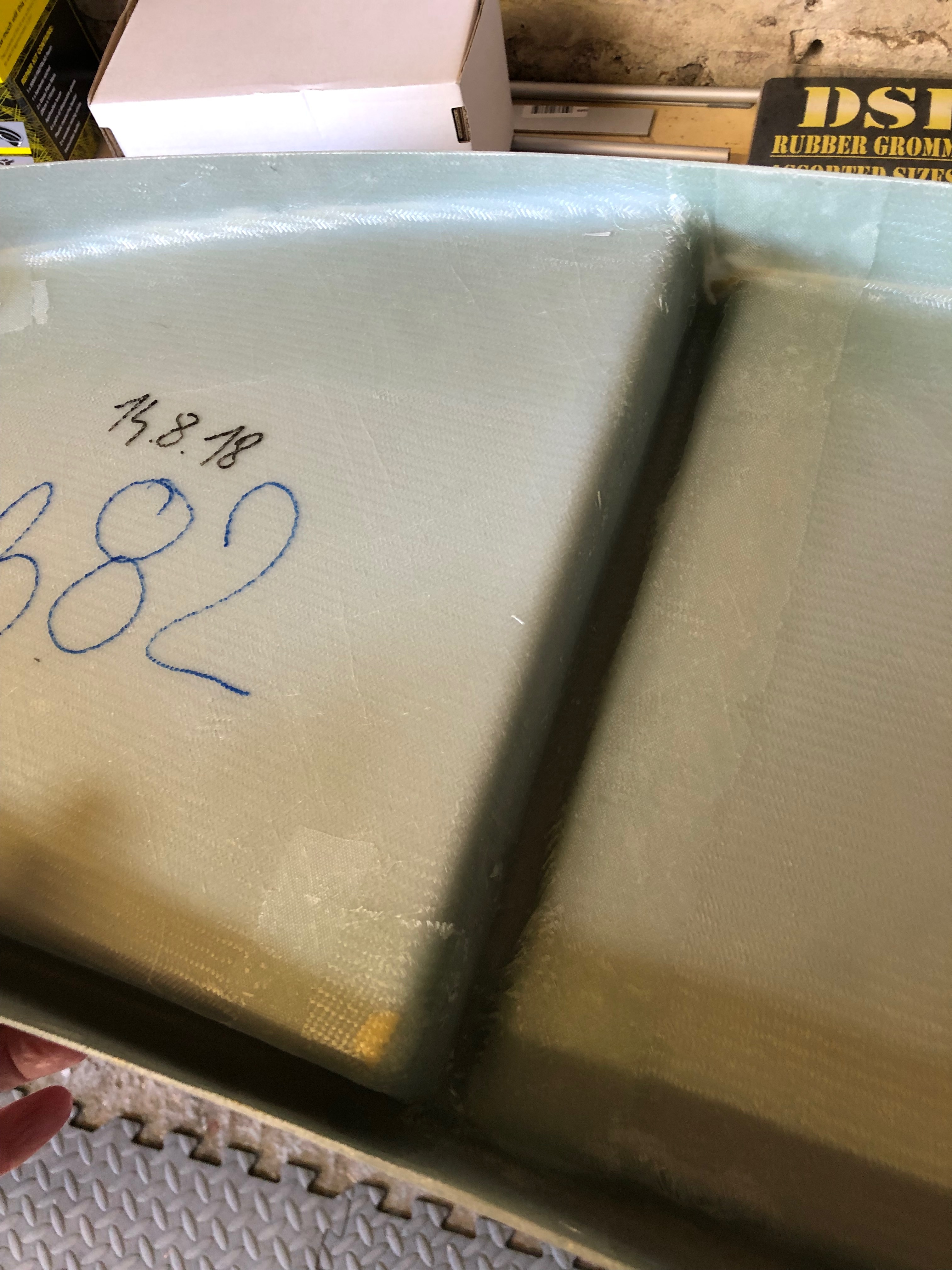
The rear of the panel showing the recess that will be removed.
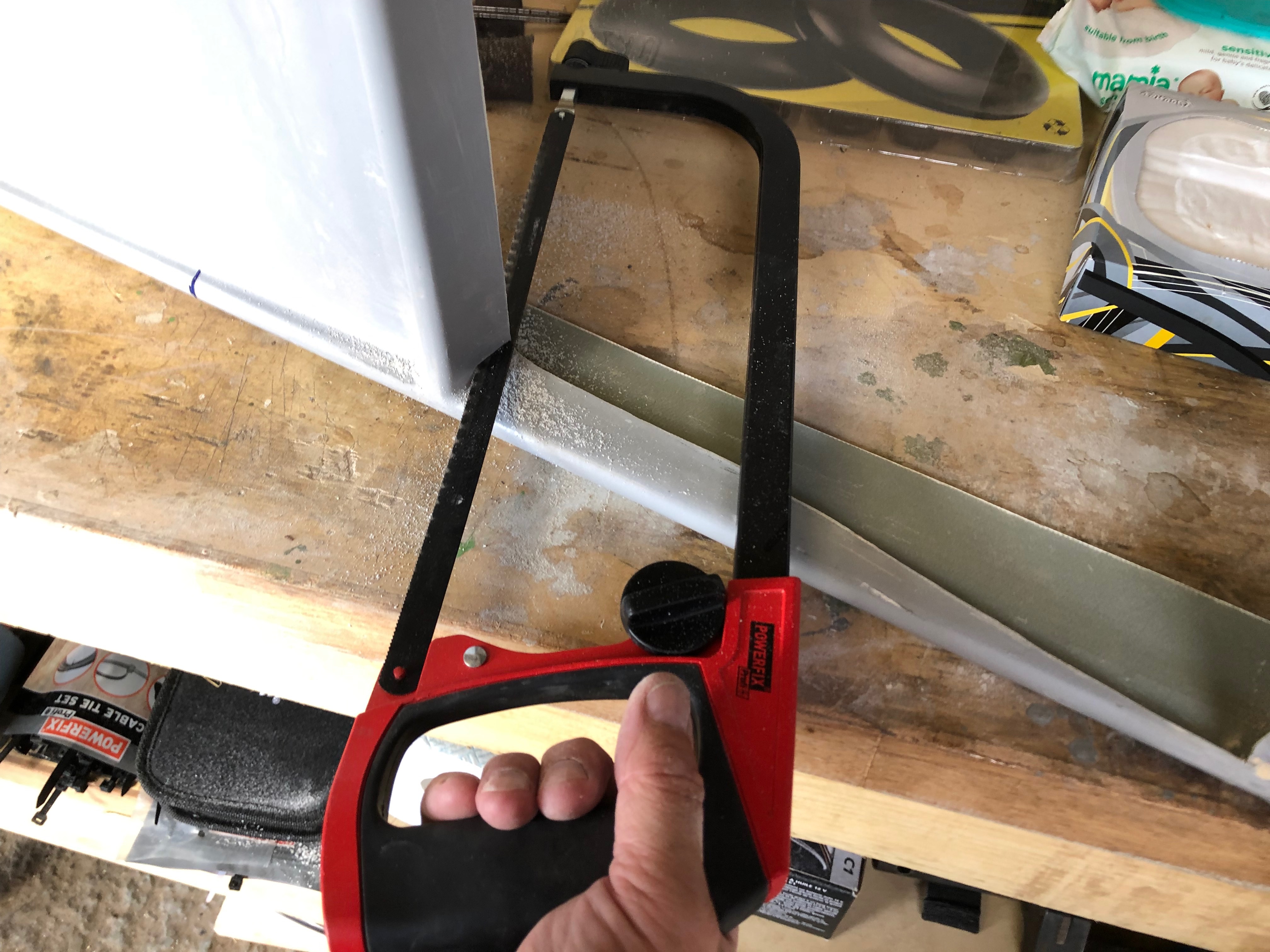
I bought a rotary cutting tool from Lidl that has proved to be very useful for this type of job as you can easily get a saw into the tight spaces.
Once the recess is cut out the edges are cleaned up with a file.
The panel with the recess cut out…
Once the vertical bar is removed the panel can be readied for the fibreglass.
The panel that was cut out can be reused to fill the void but will need to be secure in place to make sure that it’s in line with the rest of the panel.
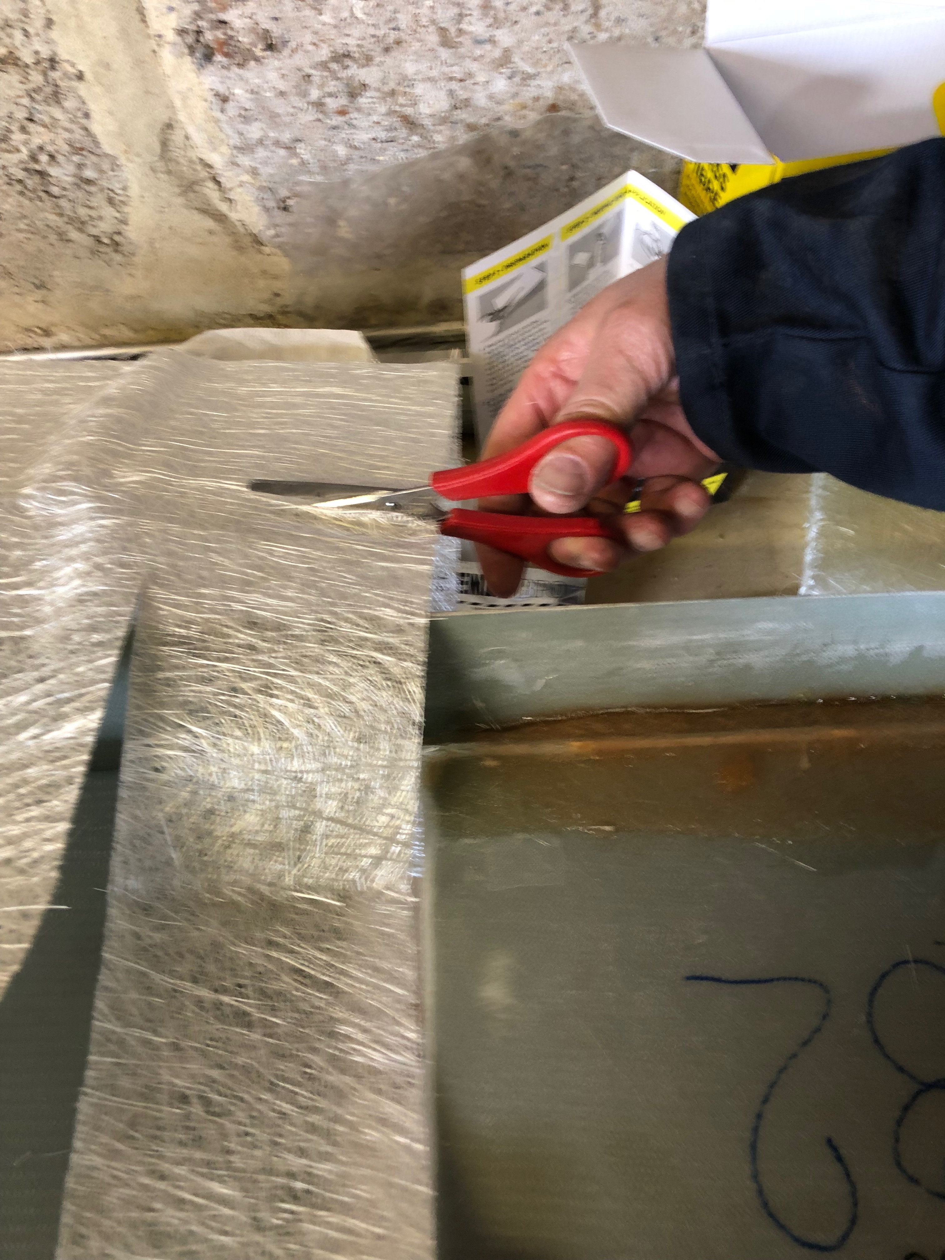
The fibreglass is cut to cover the sections that need to be filled.
The resin is made up from 10ml of resin to 1 pea sized portion of hardener.
The area that will be covered with fibreglass is ‘wetted’ with resin first to make sure that it will stick.
The fibreglass is laid on the area and the resin is dabbed on to fully wet it.
The fibreglass area after it’s been fully soaked with resin. It takes about 30 mins to set. Once fully set other layers can be laid up or the area can be sanded.
Some of the stiffness of the panel may have been lost by removing vertical bar so some strengthening may need to be introduced once the panel is cut to take the instruments.
Today we welcome a newcomer, Pilot Pooh. Kindly donated by my Cuz’ Anne. Pooh will be overseeing the build from now on and will accompany me on all G-MLSY’s flights.
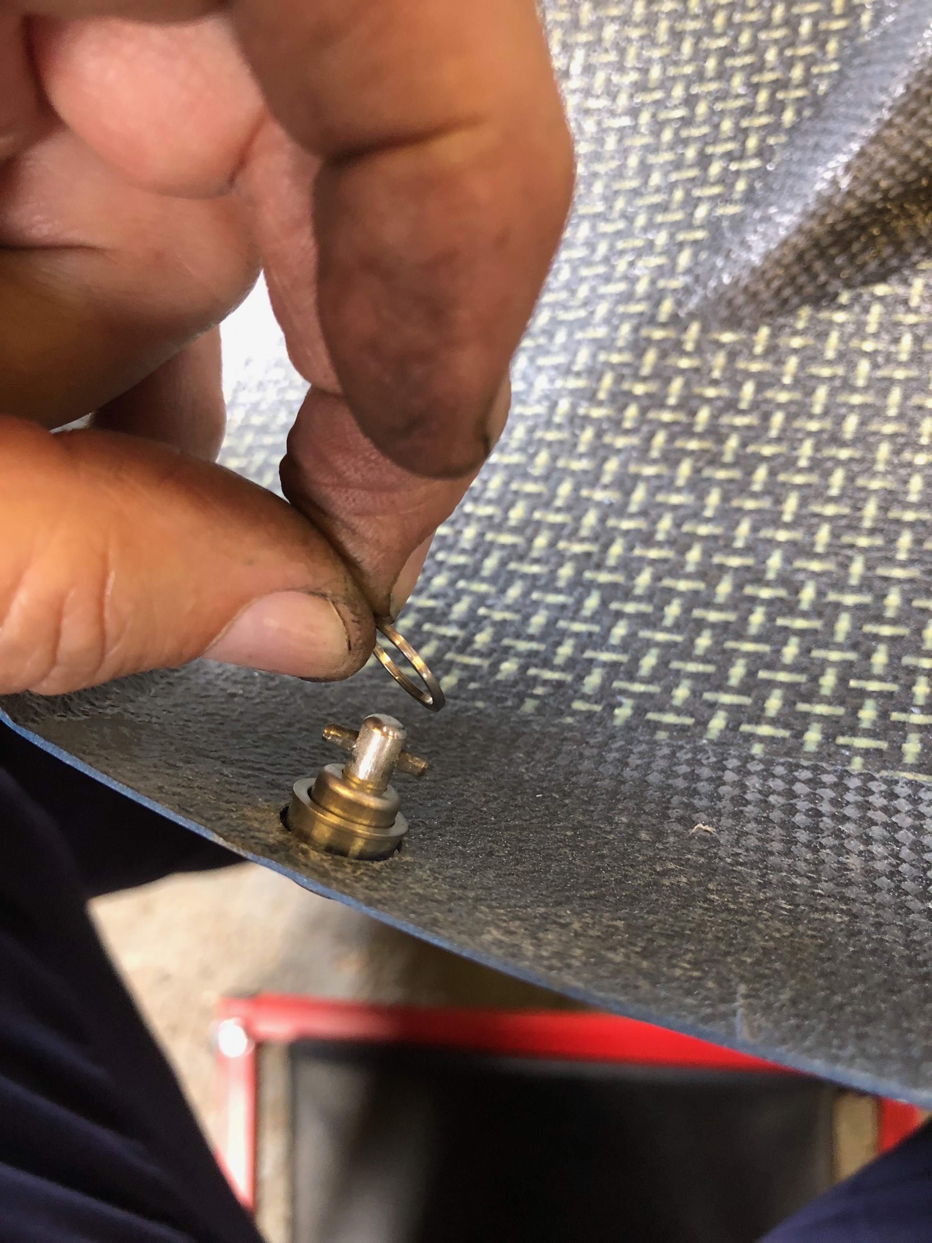
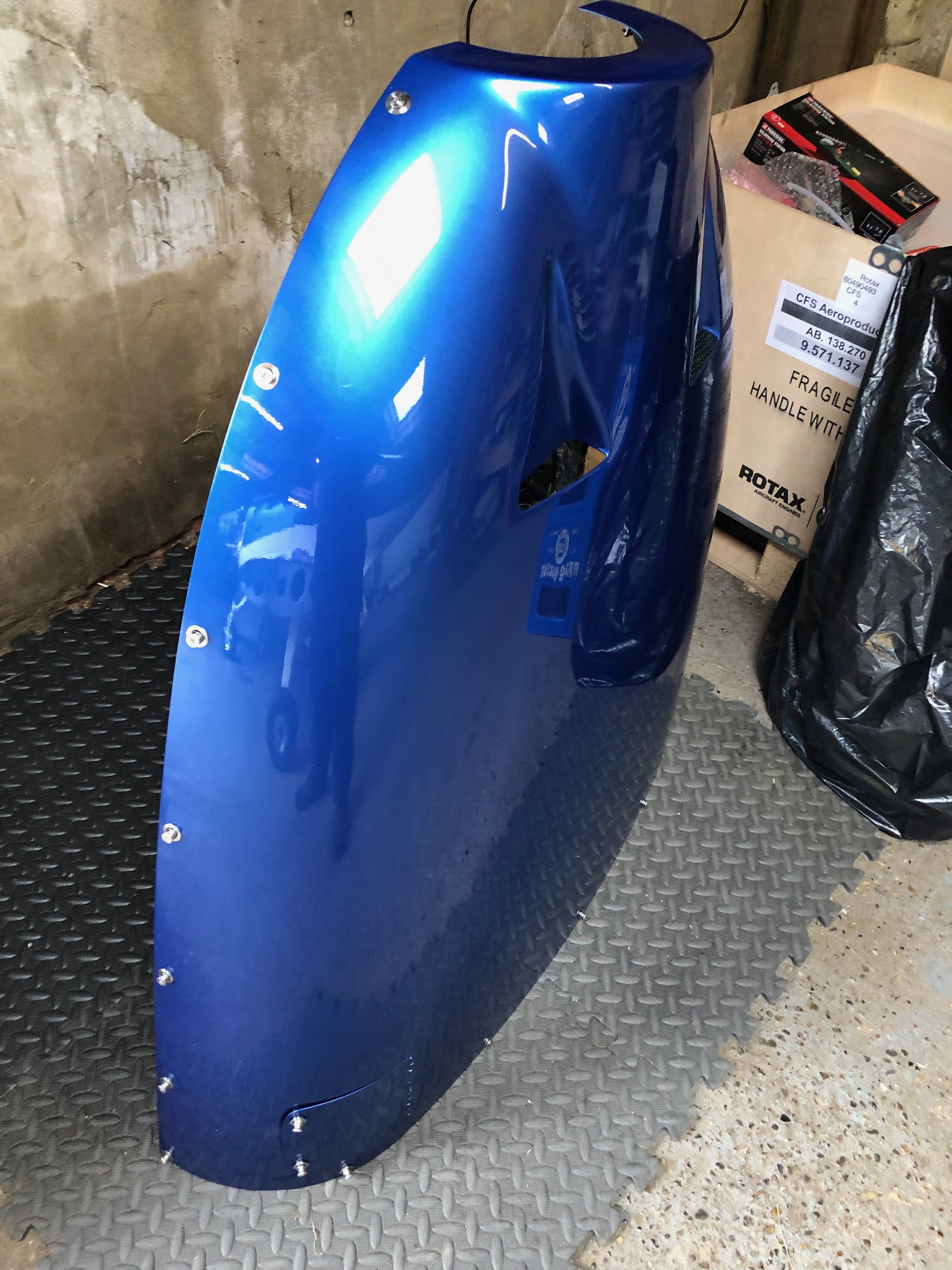
When the aircraft was painted the cowls fasteners were fitted however they weren’t fitted very well. I decided to remove all of them and start again. Having spoken to Ian Daniels my LAA inspector he agreed and said that he would refit them with solid rivets.
First thing was to use a parallel drift to punch out the hardened pin from the rivet.
Then the head needs to be removed with a large drill bit. Need to be very careful here as there is a chance that the hole could be enlarged which would cause problems when re riveting.
The fitting is removed and the old rivets are punched out.
Ian doesn’t lend his rivet squeezer out so did the job for me – saved me a job.
The result is much better, they are completely flush now and won’t rub on the underside of the cowling.
Ian in action squeezing one of many solid rivets.
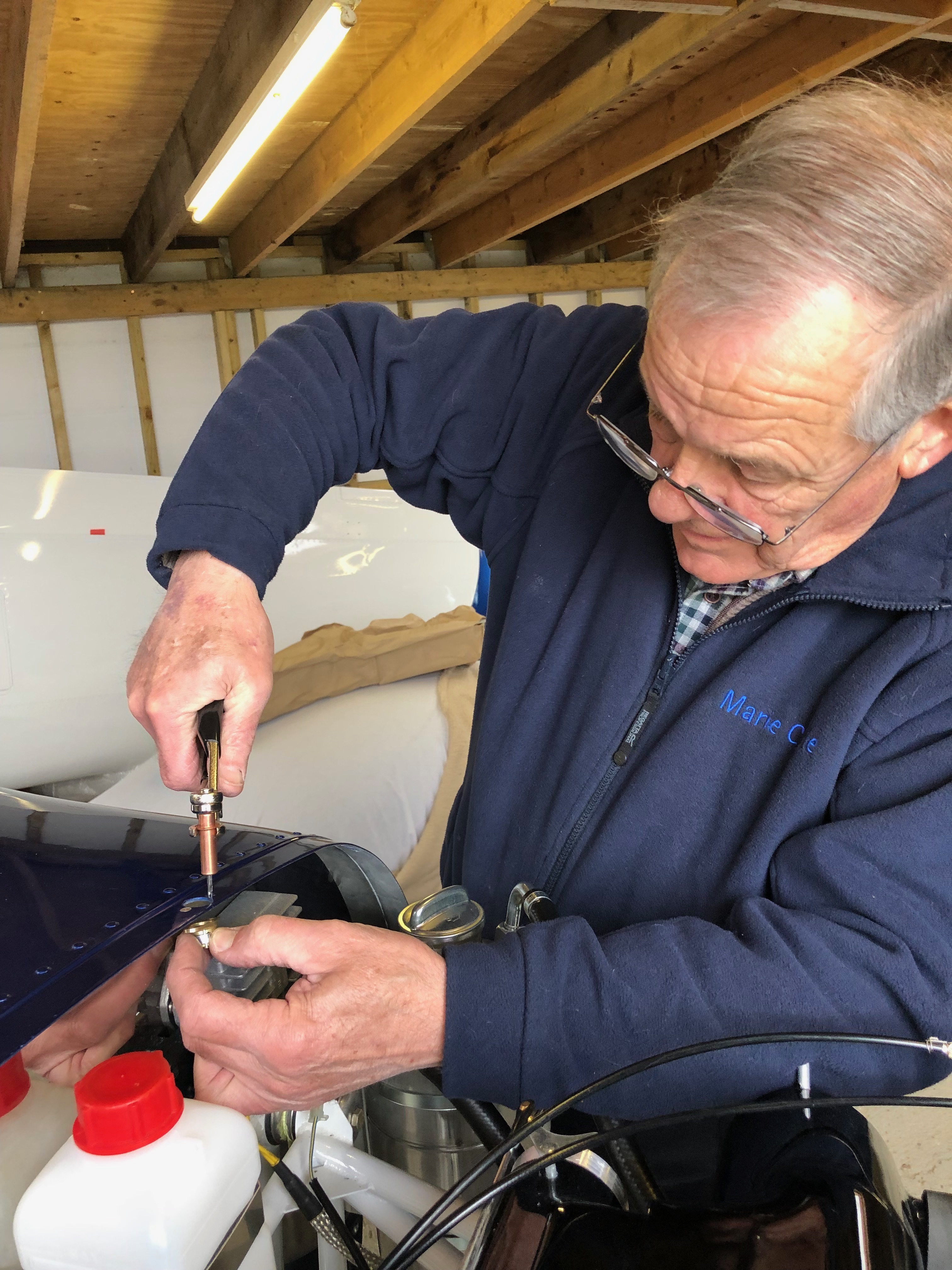
The cowl is secured by quick twist screws which are held in position by spring washers. These are installed in the top cowl.
A little fiddly to install when you first start out but they are quite easy to install with the help of a small screwdriver.
The top cowl with the quick twist screws in place including the ones for the oil inspection cover.
The bottom cowl quick release fasteners are fitted, the ill fitting fasteners will be removed, re countersunk and the fitting secure with solid rivets as described before.
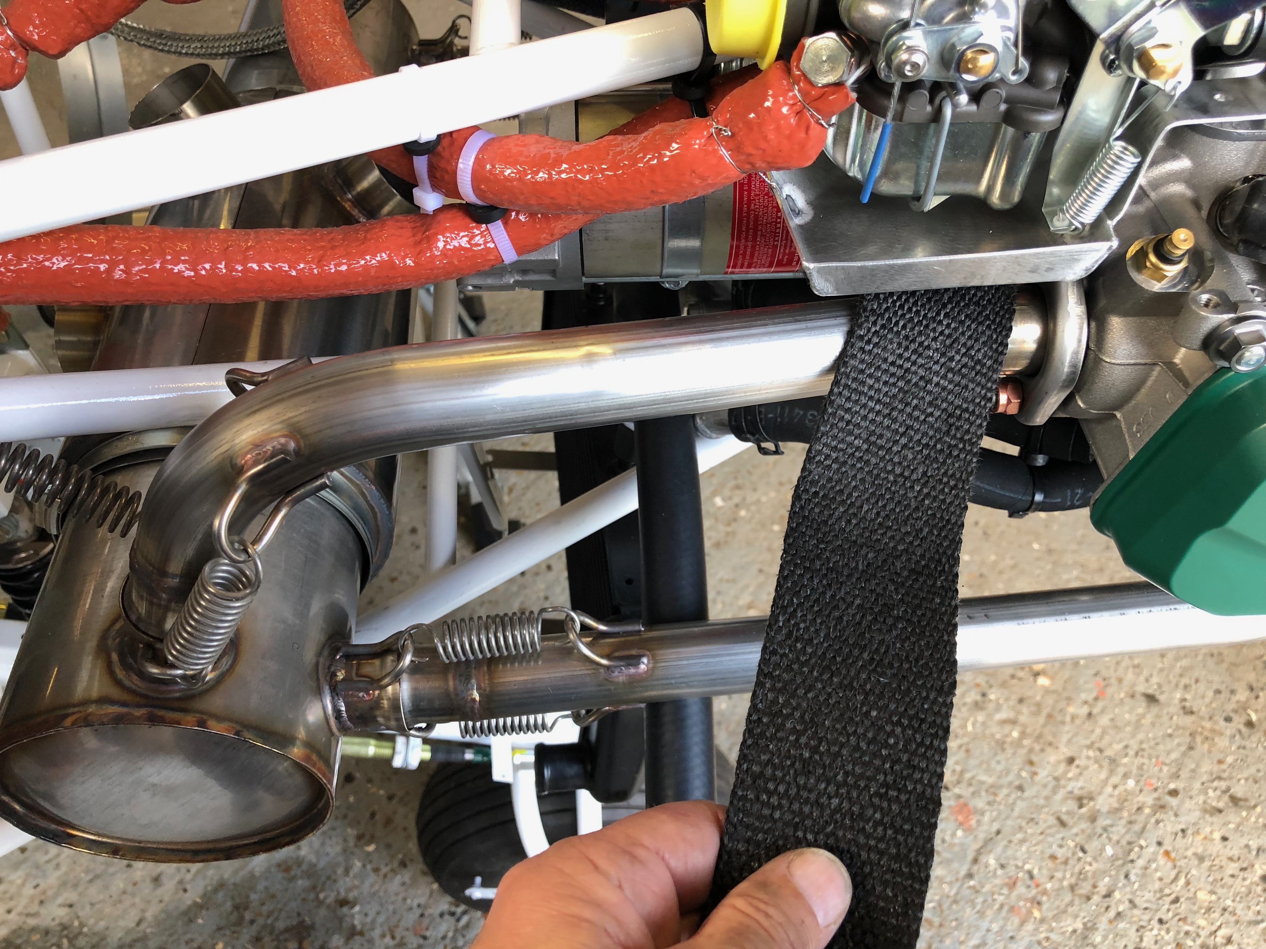
One final job was to replace the exhaust system spring wire locking I had applied as I wasn’t quite happy with the way I had done it. The wire should prevent debris being dropped from the plane and create FOD should the spring fail in service.
Now I’ve received the water thermostat I can finish the water system, install the EGT sensors and complete the exhaust system.
Thermostat, hoses & clips for install.
The thermostat is fitted behind the expansion tank.
The hoses are attached…
and the radiator bottom support bracket is installed…
Once the radiator is fully installed I can check the cowls fit properly.
As you can see there is some trimming that needs to be carried out to make sure the cowl doesn’t foul the radiator.
Looks ok from the front.
The exhaust seems to clear the cowl however another check will be made before final assembly. The gascolator is located on the opposite side to the exhaust pipe and requires a hole to be drilled which will enable fuel checks to be carried out before flight.
The installed thermostat with just a ‘stand off’ to be fitted to make sure it doesn’t rub against the adjacent engine mount.
Now the cowl fitting has proven All the clips are fitted – job done.
I purchased a Kavlico EMS kit so the EGT sensors need to be installed.
A 3.2mm hole needs to be drilled in the rear exhaust downpipes 4″ from the flange.
Once the hole is drilled and sensor fitted it is held in place with the supplied, modified jubilee clip. The sensor has a ‘collar’ that ensures that the hole is sealed.
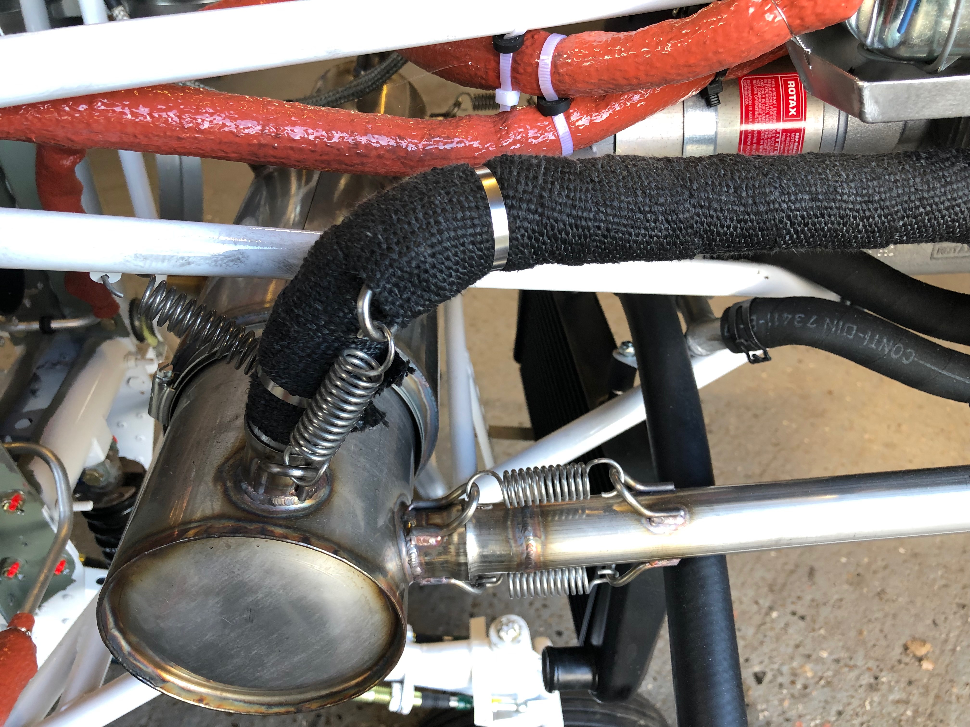
The downpipes are re-fitted and re-wrapped, securing in place with stainless steel ties.
To ensure the springs don’t fall and cause a runway hazard if they fail in service they are wire locked. Tomorrow I will fill the centres of the springs with heat resistant silicone which reduces any resonance from the springs.
A few smaller jobs, including exhaust wrapping, sensor fitting and cable oiling ahead of fitting the water thermostat that I finally received today.
The landing lights come with a couple of spade connectors that need to be crimped on…
and then slipped into the connector block. I’ll need to do the same thing when I come to install the LEDs into the wing.
The MAP sensor is fitted to the firewall in a suitable position making sure that the plug don’t foul one another.
The space between the water bottle and regulator seems to work well.
The front exhaust pipes covered in exhaust wrap and secured in place with stainless steel ties.
There’s several cables that need to be installed later in the build. Unlike the throttle cables these aren’t lined so require some lubrication.
Received at last! Good ol’ Parcel Force have had this since the 5th March but never left a card. It’s lucky I asked for an update on delivery from Silent Hektik otherwise I’d still be waiting. This is the 3rd time Parcel Force have completely screwed up on a delivery to me – I will never use them again!
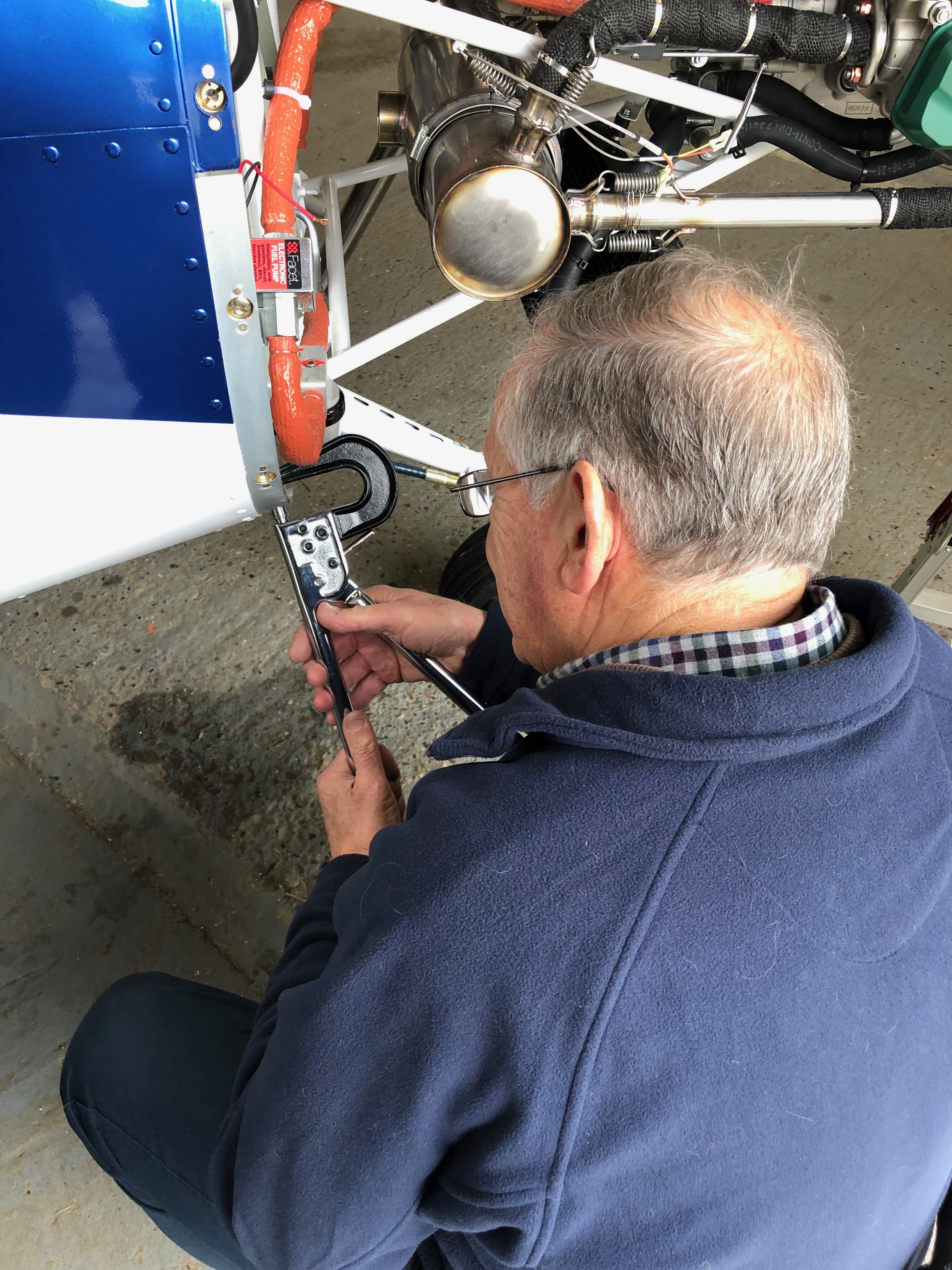
Today was dedicated to completing the brake installation and starting on the exhaust wrap.
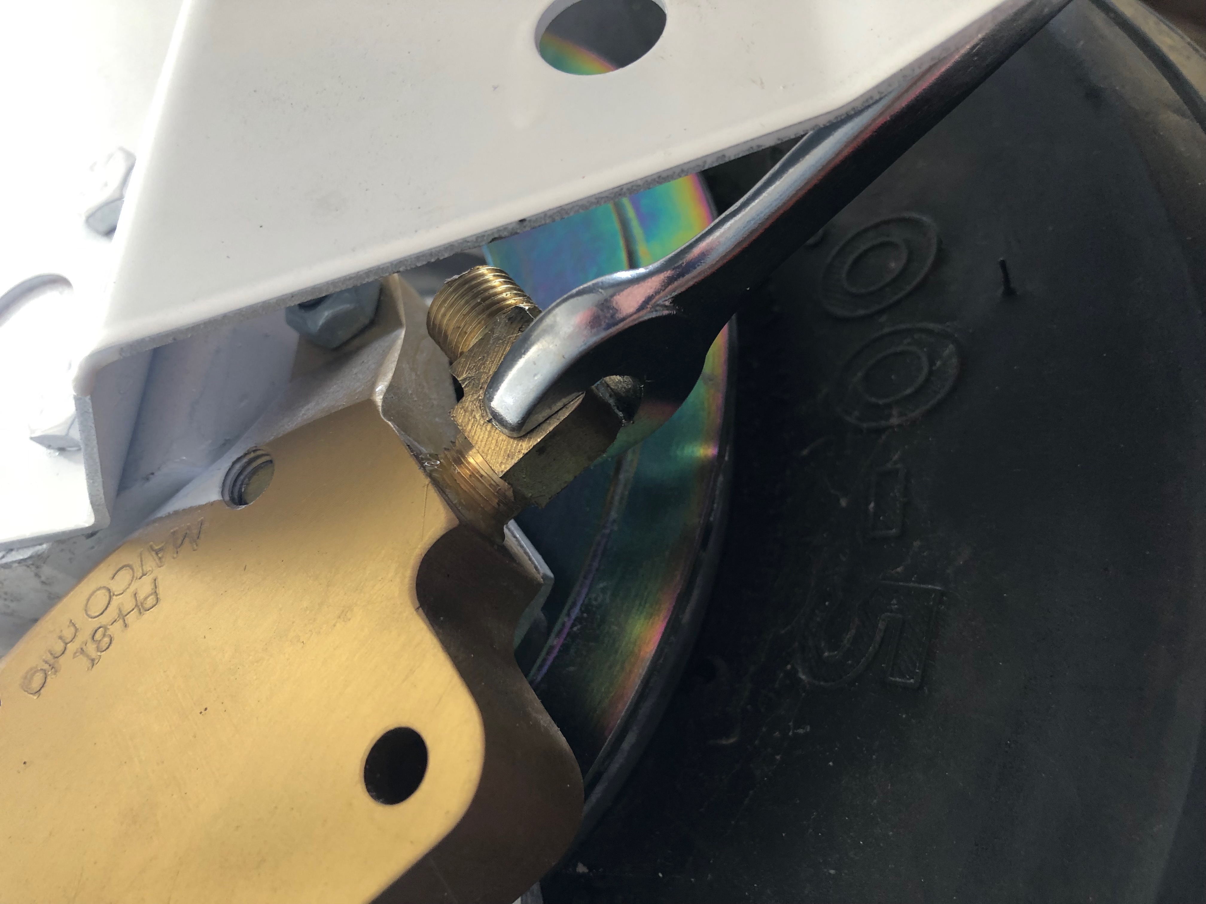
First up is to add Loctite 577 to the last two hydraulic elbows and fit them to the brake callipers.
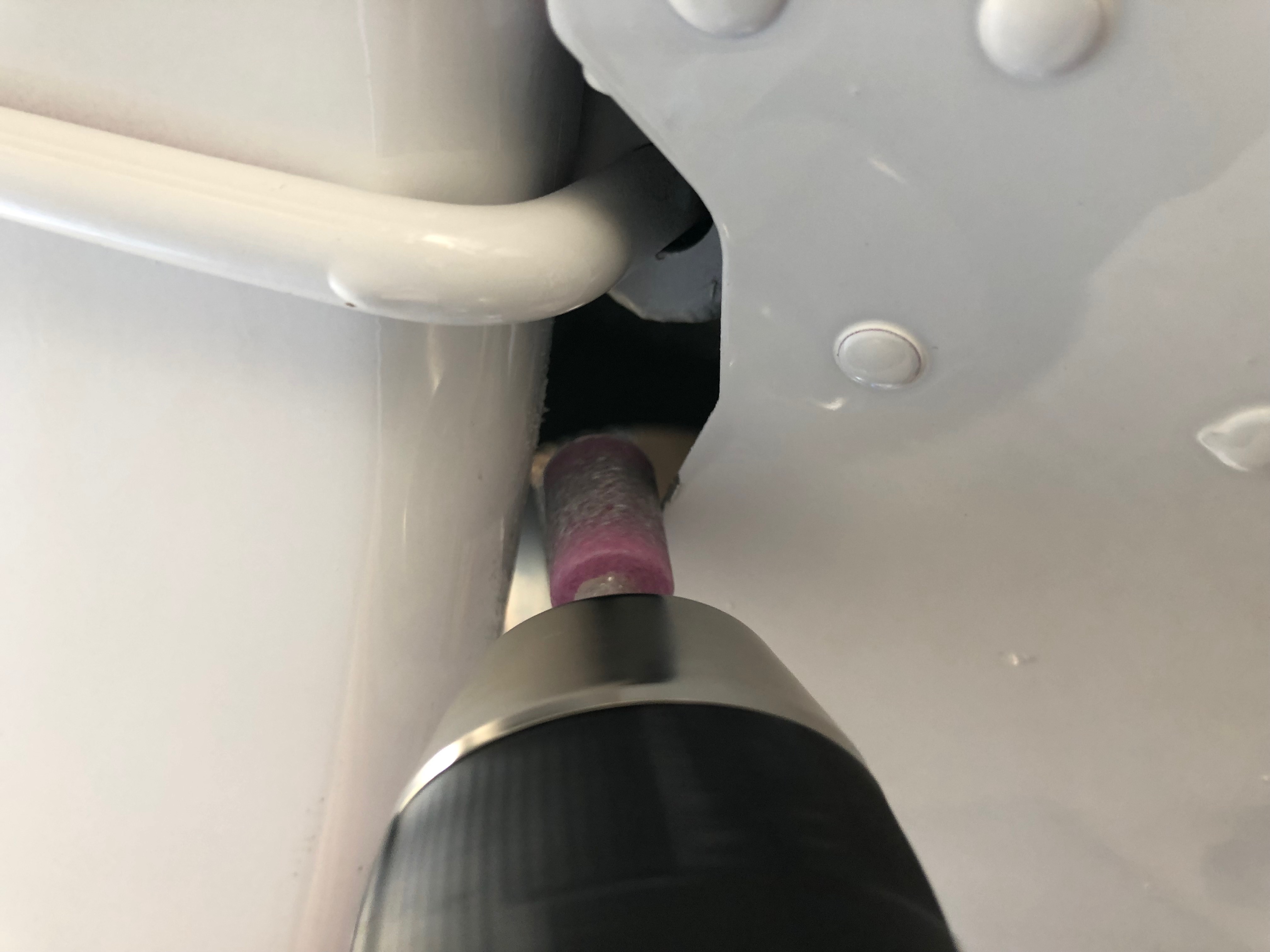
I thought it would be a good idea to cover the spiral wrap with some heat shrink tubing to protect the hydraulic pipes as it emerges from the fuselage and runs down the first part of the landing gear leg.
A slight change to the opening needed to be made to accommodate the extra width of the covered pipe.
The cover is slid over the pipe and secured in place with a tie wrap.
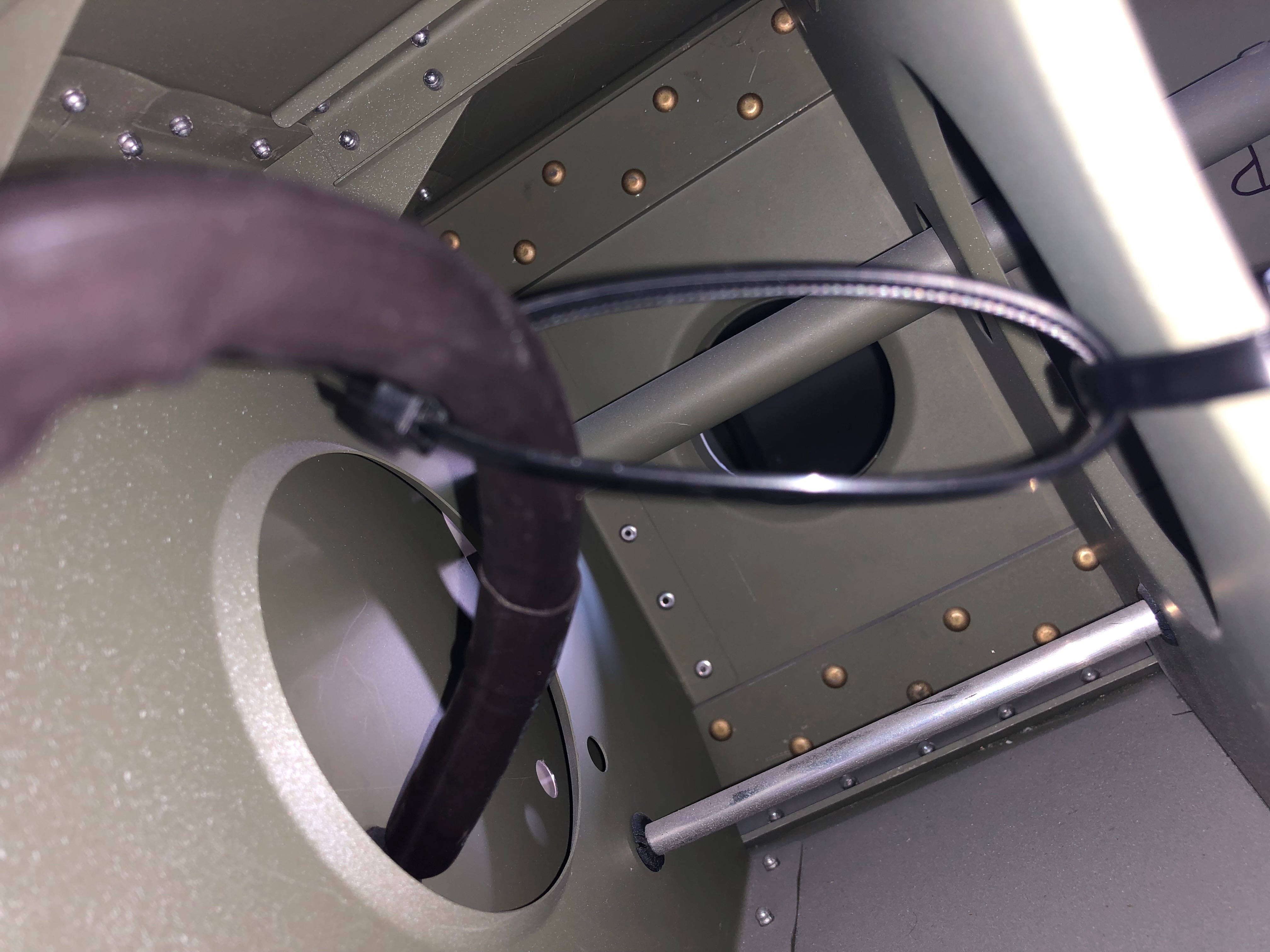
The pipe will be subject to movement when taking off and landing so the pipe is cut long to provide a loop to accommodate the movement.
The pipe run from the the master cylinder fitting to the park brake unit looked to be under stress so I removed it, cleaned it up and refitted using a different angle which allowed the pipe to ‘flow’ better.
Before tightening the compression fittings a metal anti-crush ferrule is inserted.
The pipe run runs over a ‘sharp’ edge so I added some protection to avoid chaffing.
The pipe is held lightly in place with some cable ties.
Took much longer than I expected but the brake system is complete – at last!
To protect the adjacent pipes from the heat of the exhaust I decided to cover the downpipes with exhaust wrap.
The starboard rear downpipes completed.
Run out of time but will take the landing lights home and fit the spade connectors as it’s a small job that can be done at home.
Following the build of my Bristell NG5 Kit No. 382 Registration G-MLSY