Thursday 30th May 2019

Music: Fleetwood Mac

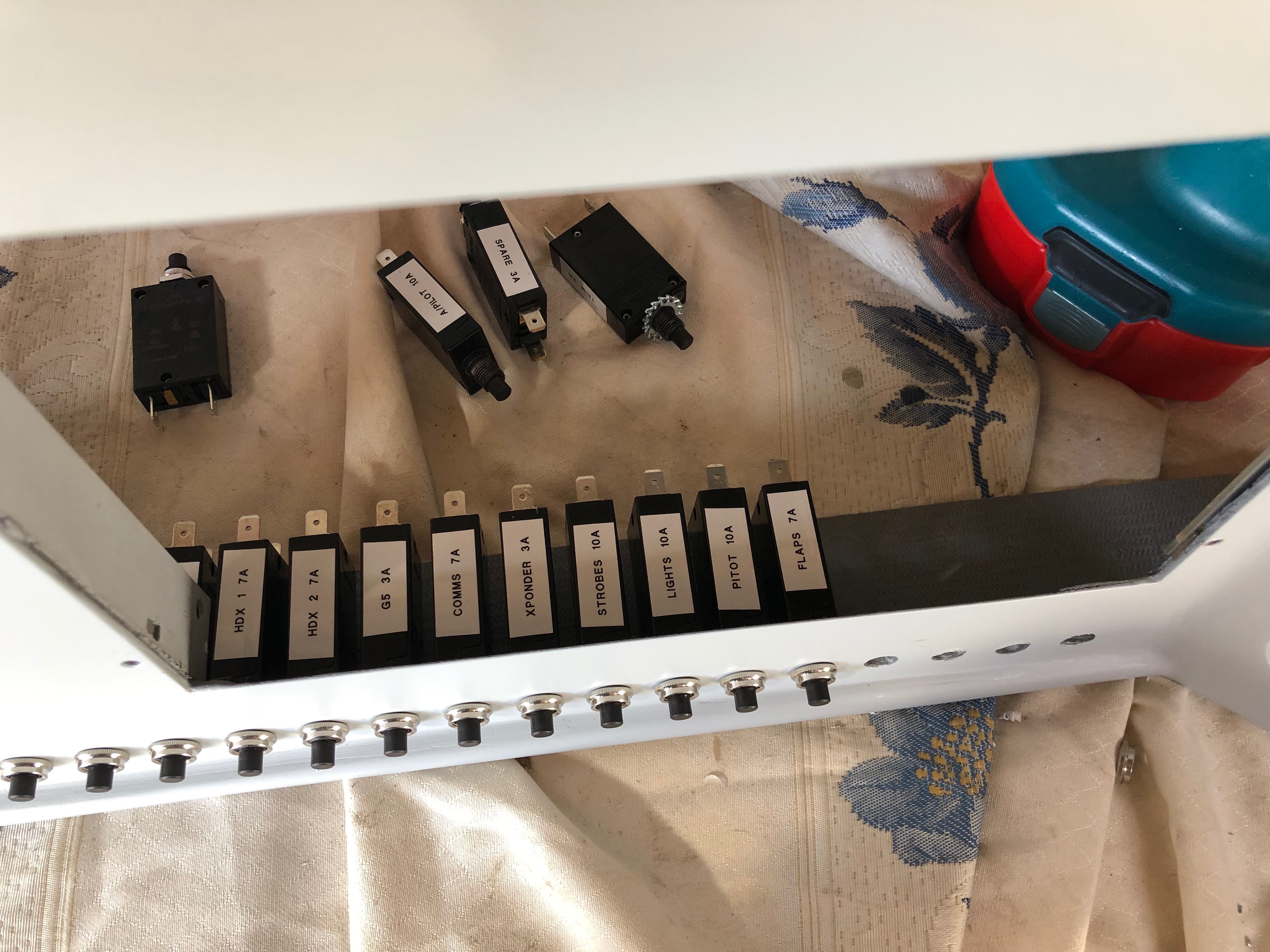
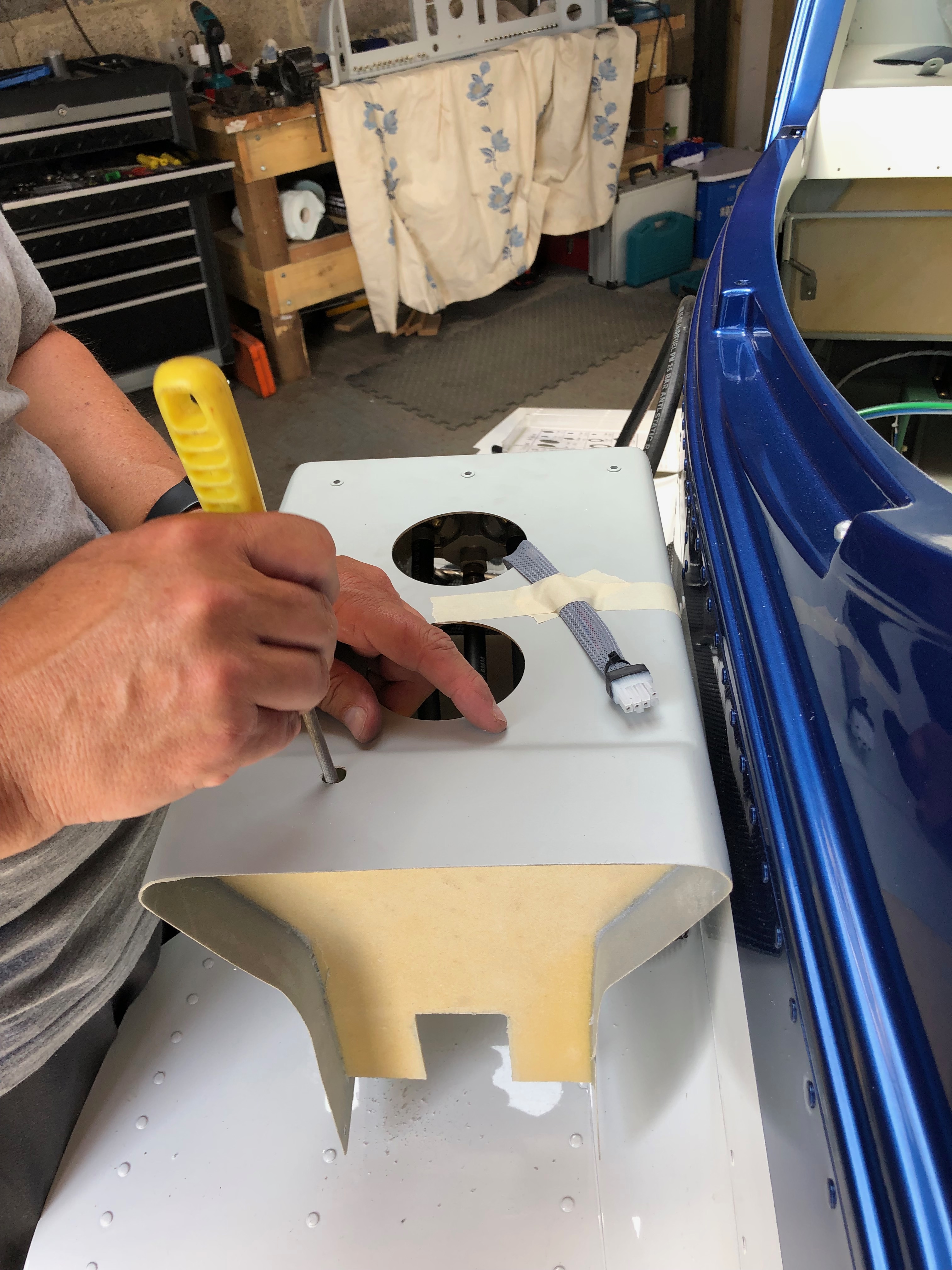
A couple of jobs to focus on today. The first is to fit the circuit breakers and second is to start the fitment of the centre console that includes the control cables for Carb Heat, Park Brake, Cabin Heater, Demist and fuel pipes to the selector and tank lines.

I’ve printed labels using an electronic printer so I can easily identify the circuit breakers and switches once fitted.
Unlike the switches that have a hex nut and can be tightened with a spanner the circuit breakers have a knurled ring that is difficult to grip. I found the best way was to adjust some mole grips so they gripped the ring firmly that allowed me to turn the the ring a quarter of a turn at a time. It took some time but got the job done.
All the switches and circuit breakers are in now. Very pleased with the result, looks quite tidy!
The cables used to control various items have to be routed so they don’t snag. After a couple of trial fits the best route from the front of the panel to the control is to exit the centre console via a hole at the rear. Three cables will exit this way and the fourth which operates the park brake will exit the end of the console and loop back in. This makes sure that the control operates in the correct sense i.e. push is off and pull is on.
With the console in place I can test the routing again and once checked I can drill the other holes.
The carb heat cable is connected to the carb heat control using a radio control model clevis.
The centre console ready to be installed showing the park brake cable that loops round and back in connect to the park brake. Without doing this the park brake would operate incorrectly.
Chris has been helping me over the last couple of days but before he left I thought I’d install a screen and power it up. With the ADAHRS unit installed and wired it’s the first time that I’ve seen it myself – looks quite impressive!

Wednesday 29th May 2019

Music: Elton John and Dire Straits

I received two pieces of good news today. The first was the dispatch notification of my Airmaster propellor which will be delivered on the 4th June. And the second was that the ignition switch that I ordered 5 days ago was arriving from Germany today! With Chris here for a couple of days he can give me a hand to do some of the jobs that I haven’t got round to like installing the rivnuts for the interior panels and fitting the wing locker seals. I continued preparing the panel for the instrument fit and working out how best to install the centre console.

Chris came down to visit and give me a hand with some outstanding items.
As I’ve decided to make the interior panels removable rather than rivet them in Chris’ first job is to install the rivnuts that will take the 3mm button head retaining screws.
Who says I’m a slave driver! A happy worker 🙂
After the rivnuts the next job for Chris is to fit the wing locker seals to ensure that they are waterproof. As the seals are not included in the kit!?!? I’ve brought some draft excluder that should do the job.
Good job done. The seals will ensure that any luggage is kept dry
I continued prepping the panel for the instruments. These aluminium ‘washers’ are to spread the load of the nuts when used to secure the instruments.

Tuesday 28th May 2019

Music: Elton John and Turin Brakes

A few jobs today. Bond the switch plates to the panel, start populating the panel with switches, mark and drill the ignition switch hole, create the looms for the servos and solder to the respective servos.

The panel cutting is largely complete now with just some USB data and power ports to add and an ignition switch. I’ve sprayed it with the paint matched to the interior so it’s ready to have the switches added.
To ensure that the spacing was correct I marked and drilled the holes in a piece of 20 x 1mm aluminium and then drilled through the panel. This is now bonded to the back of the panel to give the switches a solid feel during operation.
I’ve riveted on a couple of spade tabs to the end of the strip just in case I need to use them for earthing.
The switches are installed and tightened with a 14mm ring spanner. Have to be careful here to line them up correctly and make sure that I don’t mark the paint!
I’m still awaiting the arrival of my ignition switch that’s on its way from Germany but luckily Ian had one that I could use to get the positioning right and drill the hole. Now they are in I can leave it to set before installing the circuit breakers.
Now onto creating the look for the autopilot servos. Dynon sells a servo wiring kit with 20′ of multicoloured wire of the correct gauge, it includes 2 female and 1 male D9 connector. There’s ample wire to make 2 looms from it so I’ve cut it in half and bundled the wires together in readiness for soldering to the servos and terminating with a female D9.
There’s a few things that’s important to remember when soldering;
1) Match the colours.
2) Make sure you slide on the heat shrink tubing before you start soldering.
3) Mark each end of the loom so you know what wires you’re working with.
Soldered and protected. The final bit is to slide another piece of heat shrink one the bundle to keep it all together and…
protect the loom with some conduit. I’ve decided to use split conduit from the servo to the throttle quadrant and then I’ll use poly sleeving from there to the connector block.
One of the things that I’m trying to do here is to keep everything neat and tidy for easier maintenance in the future if needed.

Friday 24th May 2019

Music: Easy 80’s

After cutting the holes for the switches, circuit breakers and panels the holes for the retaining screws can be drilled and the panel painted in readiness for the avionics to be fitted.

Most of the instruments sit on top of the panel but the prop controller is fitted from behind so it’s a little more difficult to drill the holes correctly.
Once all the holes for the instruments and screws have been drilled the panel is sanded down with 600 grit wet & dry and then is can be primed with plastic primer.
The rear of the panel showing the strengthening that I’ve installed.
Pleased with the panel so far. Just the ignition switch to fit and a couple of top coats to match tie interior and then I can start installing the switches, circuit breakers and instruments and then start the wiring.

Thursday 23rd May 2019

Music: JT and the Clouds and Daily Mix

Today was a little frustrating with news that the ignition switch wouldn’t be delivered until August! Grrr…

Well the day was dominated by checking up on another vital component, the ignition switch. After placing the order with a reputable aviation company I was told there would be a delay as they were out of stock (despite their system saying that they had them in stock). They advised that I would receive the switch on the 22nd May which I agreed to. As I hadn’t heard anything from the company I checked with them on Wednesday. They said ‘don’t worry sir we’ll drop you a line and let you know today’. Well that was yesterday and nothing! I phone them today and they said ‘don’t worry sir we’ll drop you a line and let you know today’. Surprisingly I said No! give me a call as soon as you have checked. 20 mins later and the voice on the other end said ‘It’s not good news sir – expected delivery is now August!’
I do find it amazing that customer service doesn’t seem to feature at all in some companies operation and they just don’t keep customers updated with any delays. I won’t name the company as it’s happened more than once during this project with different suppliers.
2 hours later and I found another supplier. It’s been despatched within minutes of placing the order and it’s on its way from Germany with delivery due in a couple of day.
With all the holes I’ve cut in the panel it needs a bit of support! I had a think and believe this to be the best solution. I’ve cut a couple of pieces of 25mm aluminium angle and drilled loads of holes in it so it will ‘key’ onto the structure better.
I’ve also drilled some holes in the side of the support braces so I can use them to secure wires behind the panel with some cable ties. The angle is secured in place with glass fibre cloth.
A layer of glass fibre is set first that the support will sit on and then another layer of glass fibre is set over the top. This should provide a very strong bond.
This is how it will look once finished. Another layer of glass fibre needs to be laid over the outer supports to finish off but I’ve run out of time today due to the switch fiasco so will finish of tomorrow!

Wednesday 22nd May 2019

Music: ELO and Elton John

The trim indicators and manual prop switch holes need to be cut today. I’ve also ordered the paint for the panel that matches the interior panels, it should be ready tomorrow morning so I’ll paint it once I’ve cut the rest of the holes in the panel.

Same procedure to cut the holes for the trim indicators. Finishing the holes with a file.
A trial fit of the indicators. Looks about right.
The panel and centre console installed to trial cable runs. Looks quite good even if i say so myself! With all the cut outs I need to strengthen the panels I’ll attach some aluminium angle behind the panel with fibreglass.
The final control to be installed is the manual switch for the prop. The cut out is made in the same way but I’ve decided to install this control in the centre console just in front of the throttle.

Tuesday 21st May 2019

Music: Soul Classics 1970-1975, Embrace

I have the Garmin G5, Airmaster prop controller, Flap switch and the Dynon sub panels to do today. The sub panels cut outs aren’t just rectangles so I need take my time and as they say measure twice and cut once. In reality I think I’m measuring 4 or 5 times and cutting once which is taking some time but it’s got to be right otherwise it’ll spoil the look of the cockpit.

The G5 and prop controller need 79mm and 57mm holes so these are needed to get a neat hole.
I’ve finally decided on the layout. This look like the best option with the panels that I need to install. I’ve also borrowed an ignition switch from Ian to position on the panel before my one is delivered.
Marking up the panel for the prop control hole, making sure that its equidistant between the G5 and the flap control. These are the easy holes to cut as they are circular and along a single line.
This is the template that Dynon supply with their panels. This template is used for the 3 of the 4 cut outs.
I’ve thought of different ways to cut the holes out. Jigsaw, Fretsaw and drill. Although I have very fine blades the jigsaw snagged when I used it on the main panel cut outs and I don’t have a jigsaw so small holes are drilled around the outline. Once drilled the material between the holes is cut with a Stanley knife.
Once cut out fine adjustments are made with a file. The audio panel cutout at the bottom in this pic is the only one that’s a rectangle which made it easier but the template seemed to be too large so it’s lucky I measured the unit before I cut the hole!
The first controller panel installed to test.
The last job for today is to drill the hole for the flap controller and cut the plastic rod for the knob.

Still a little long so another cut needs to be made.
These pictures of the avionics have helped me visualise the panel layout before cutting and can finally be binned now all the holes have been cut.
The instrument panel, with components installed. Quite pleased with it but it’s taken a lot of time decide on the layout and cut. Some more cut outs need to be made for the trim position indicators, Magneto switch and USB power.
A late finish tonight. Looks like I’ve missed a lovely day!

Monday 20th May 2019

Music: Elton John and ELO.

Time to cut the main panels out. It’s crucial to get this right otherwise the panel will look terrible so lots of time measuring and marking and repeating the process before any cutting takes place.

Dynon don’t supply a template for the HDX screens which seems strange so I made one up out of cardboard and then measured it against the rear of the panel to make sure it was the right size. There nothing worse than measuring, cutting and then realising that you’ve cut the wrong size!
The panel is made from glass fibre so I cut the first one out using a fine toothed jigsaw. It was ok but there was a fair amount of vibration when cutting it.
I decided to cut the other side out with a Stanley knife which took a bit more time but gave a good result. Both sides needed cleaning up with wet & dry to finish them off but both sides were spot on.
I cut the air vent hole out with a 51mm holesaw.
The Aveo air vents, Skyview HDX screen and some switches installed. It’s taken some time to get this far but I have to make sure it’s right. Tomorrow I’ll continue cutting holes for the G5, prop controller and Dynon sub panels.

Sunday 19th May 2019

Music: Fleetwood Mac

I wasn’t expecting to do any work today but the opportunity came up to visit my workshop.

I have come to the stage where I need to finalise the design of the panel. I’ve designed the electrical circuits so know how many switch and circuit breaker holes I need so I can drill those. I’m still awaiting the key switch to arrive which is due in a week or so but I know where that will be located.

Another look at possible panel layouts and to see how the logistics of the panel layout will work at different stages of flight.
Sitting in the normal flying position allows me to see how high I can have each unit before the glare shield obstructs the view. The main panels are positioned directly in front of the respective pilot positions which I believe is the best position. I have the switch layout right but still am not quite decided on the sub panel layout. I quite liked this layout but it is a bit cramped so I probably won’t use it.
I thought the best way to ensure that the holes are located exactly where they need to be is to mark a strip of 20 x 1mm aluminium with the spacing and centres.
A centre punch is used to mark before drilling ensuring that the drill doesn’t move off centre.
After a pilot hole is drilled I can open up with a 12mm drill for the switches and 10mm for the circuit breakers. I tried using a step drill on a piece of scrap first but the aluminium seemed to soften and bung the step drill up so a normal HSS drill was used instead.
All the holes now complete. They will require cleaning up with some wet & dry before they can be used. The panel hasn’t been painted yet but I’ll do that once all the holes have been cut. Tomorrow I start on the main panel cut outs.

Friday 17th May 2019

Music: James Taylor and Oh Wonder

A couple of days away to do some flying and meet up with an old mate for a beer or two and now back to the grindstone!

A couple of items to complete the installation of the primary power system. The power and earthing arrangements that I’ve decided to use necessitates rearranging the items on the comms tray. Once this stage is complete and with virtually all the other activities complete until the prop arrives it’s time to move on to wiring the all the systems together. It’s getting to the stage where I need to finalise my panel design and start cutting it out. I haven’t decided whether I will do it myself of get a company to water cut it.

I decided to use a neat 20 way earthing block (VTE 120amp busbar) that complements the power distribution block that I’ve already installed. Where to mount it was an issue but thought the comms equipment tray would work well and shouldn’t produce any interference. So an hour or so was spent trying to work out the best position to ensure ease of access and sensible wiring runs.
I think this is the best option. I made up a short earth wire terminated with and 8mm on one end to bolt to the firewall earth stud and 6mm the other to connect to the busbar. This solution will provide 20 feed and earth connections that should be adequate as I have 15 circuits to cater for in the current electrical design.
The last wire to add is an earthing strap that is bolted on to the starter motor. This will ensure that the start draws all it’s power from direct connections and not through the aircraft frame or engine mount .
The completed primary power system.
Onto running the wires and harnesses in that I’ve made into the aircraft and ensuring that they don’t get damaged during service. This is the ADAHRS network cable. I’ve chosen expandable braided PET cable sleeve. It’s tough, very light and is easily installed.
Once the cable is run in it can be secured with cable ties. This will be hidden behind the interior panels that I’ve decided to make removable so I can get to these when I carry out my annual checks.
For harnesses with connectors on I’ve chosen flexible split conduit which is tough, and light but a little more bulky. The split in the conduit allows me to slip it over my pre-made wires.
With all the wires and services that will eventually be installed I have to make sure that the installation remains neat and tidy that will facilitate easy maintenance, good protection of the various services and easier fault finding if I ever have a problem.