Tuesday 14th May 2019

Music: Oh Wonder, Paolo Nutini

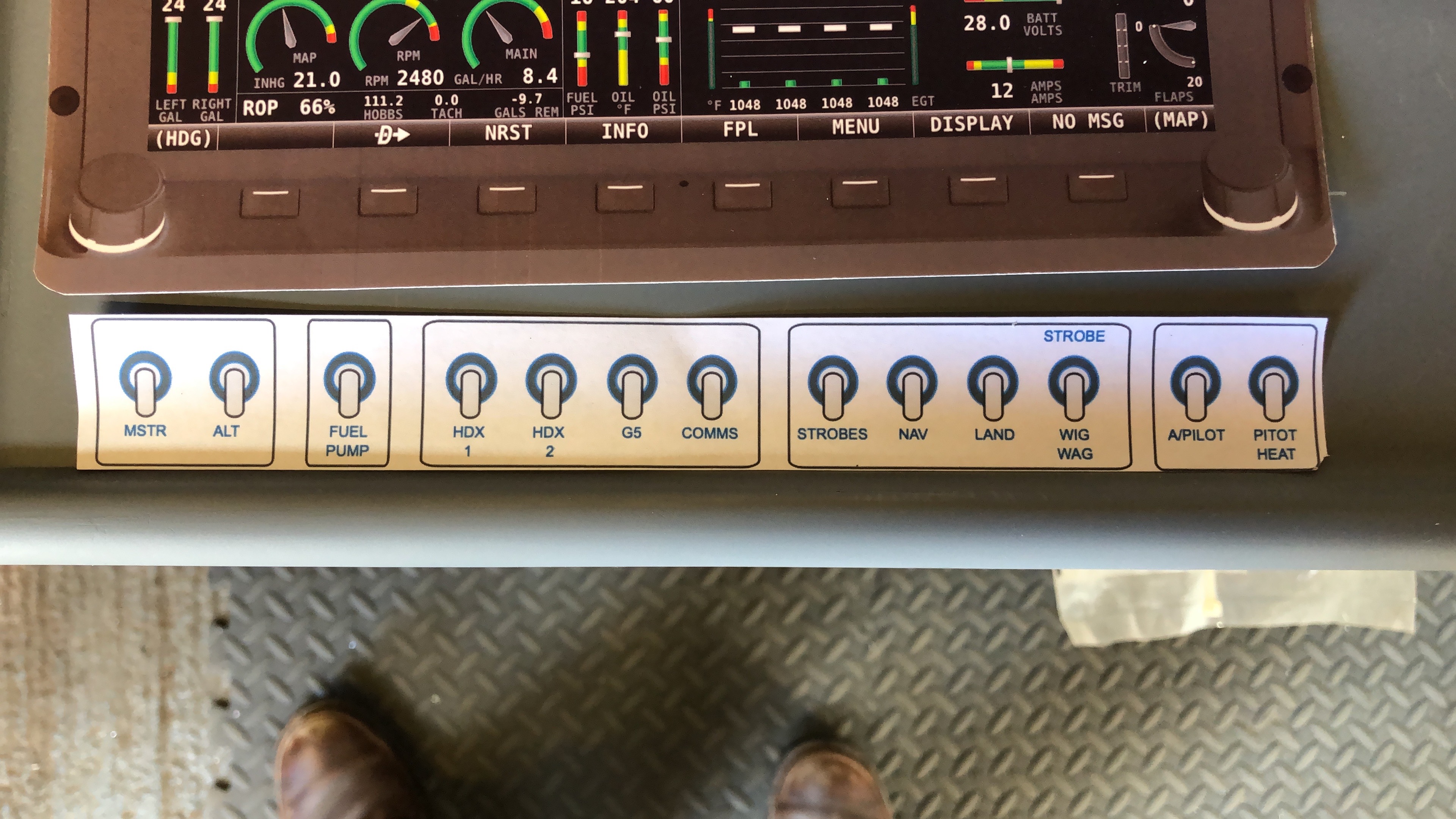
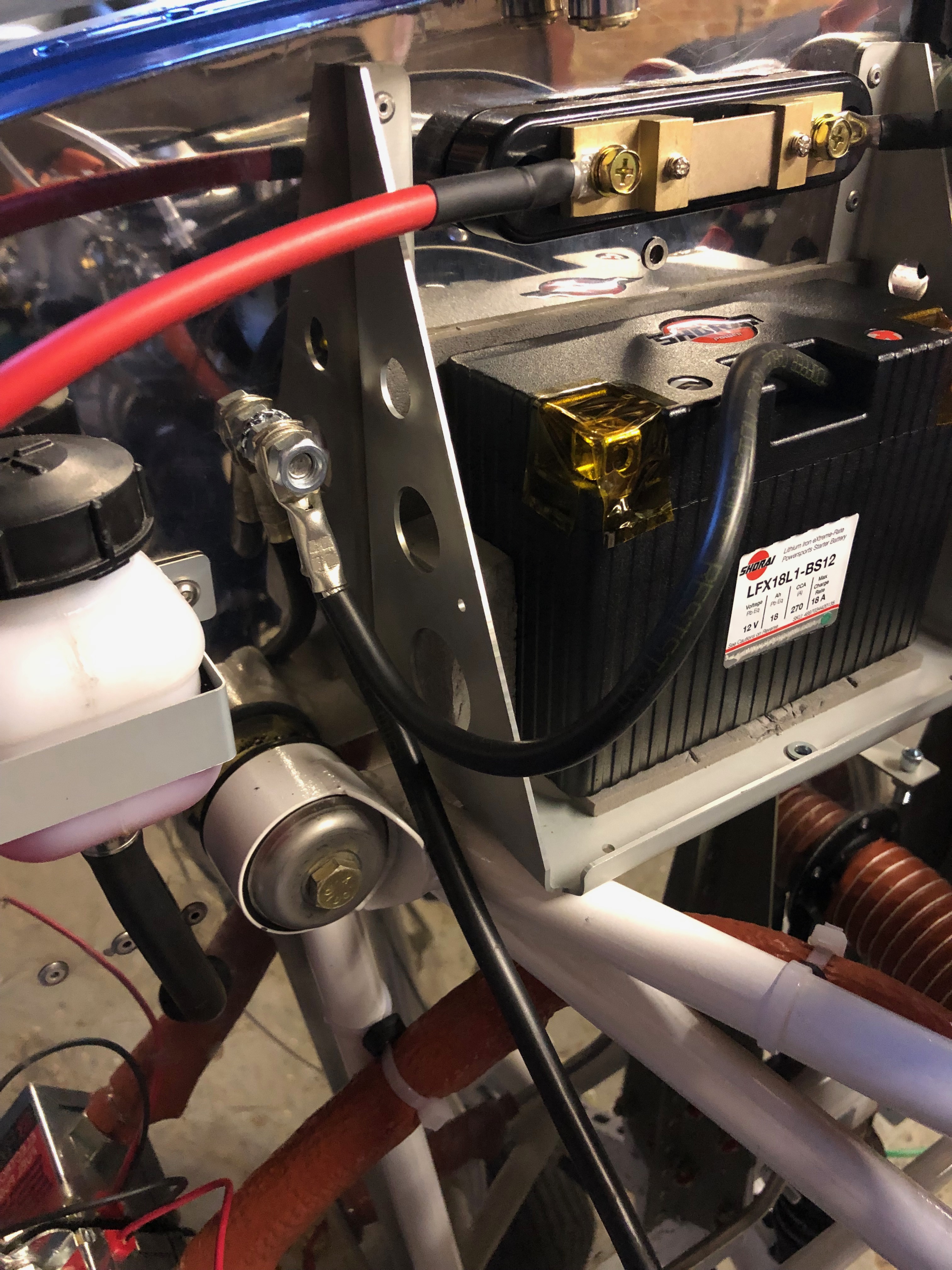
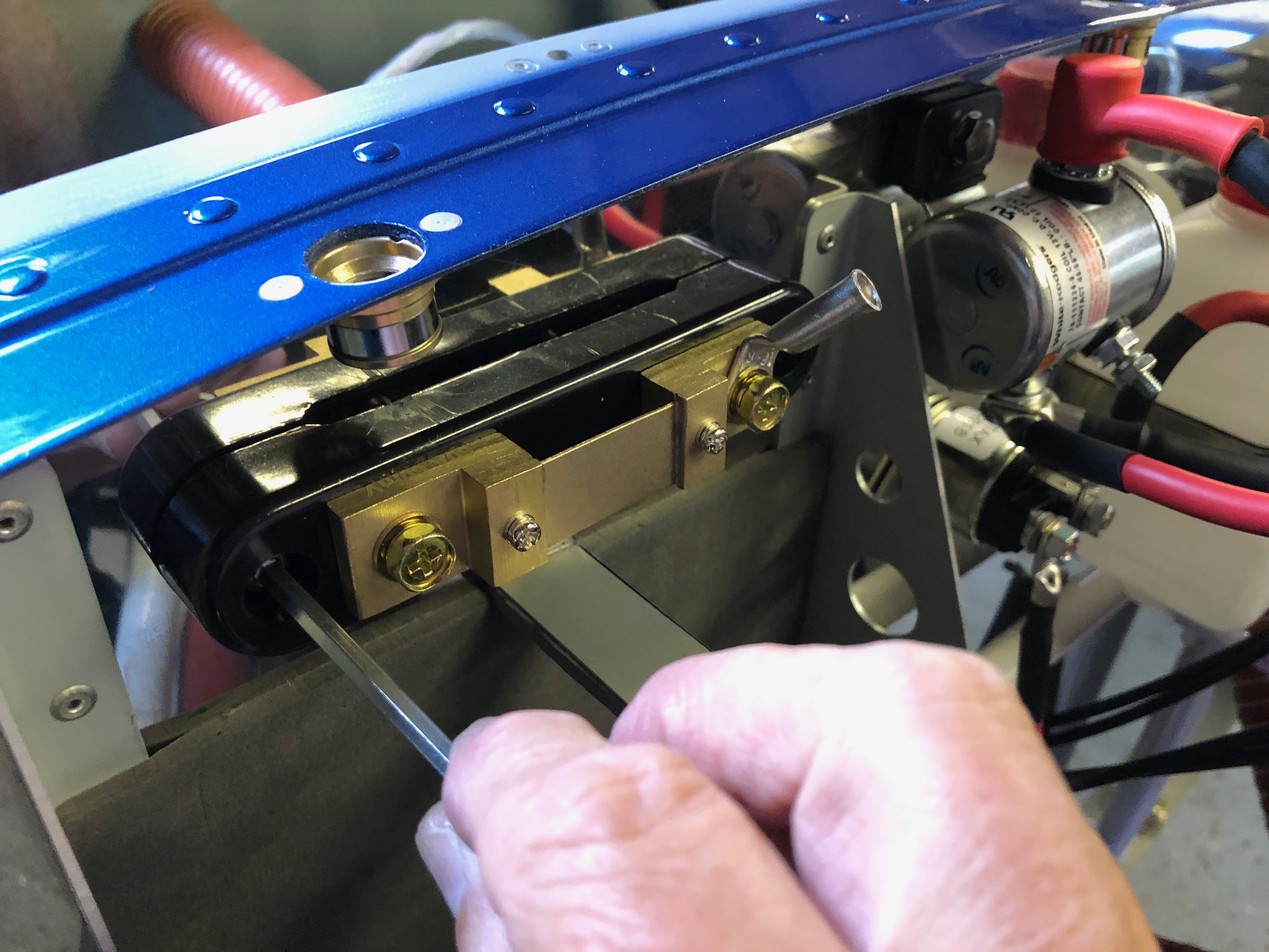
Today I focused on completing the primary power system and testing switch pitch layouts before fitting to the panel. Robin May and Dave Bennett came down for a visit and check my work out to make sure it was up to standard after which we went for a quick lunch in the Prince of Wales pub that is just across the road from the airfield. It was great to see them both.

Rob and Dave sporting cheesy grins just before departure. Estimated time to get back to Finmere, just 33mins!
I mounted the circuit breakers using a piece of 20 x 1mm aluminium to check on spacing…
and then did the same for the switches. I will have more interaction with them whilst flying so need to make sure their not too close together. 20mm spacing seems to be fine but will do a final check before drilling the holes in the panel!
This is the likely layout of the switches. I’ve tried to order them logically based on start up and scan cycle.
Each of the heavy duty wires that are used for the primary power system need to be terminated. I considered ordering the wires but thought it would be better to make them up myself just incase I changed my mind on the positioning of components. This is a handy tool for crimping terminals on heavy duty wires that can be used by either clamping in a vice or hitting with a hammer. The latter seems to work a treat!
The +ve power needs to run through the firewall to a position behind the instrument panel so an additional hole needs to be drilled and protected with a rubber grommet.
After a lot of research and scouring the internet I found this busbar. The wire is connected to the unit and protected by a rubber boot, a cover fits over the whole unit to protect against shorting.
The +ve side complete. Now to move on to the -ve side and earthing arrangements…
The -ve needs to be attached to the airframe, engine and -ve busbar so I’ve added a stud that I can connect the engine and battery connections to. Thats it for today and quite pleased with the progress made however it all takes a bit longer than you expect!

Monday 13th May 2019

Music: Elton John, Dido

With the delivery of a number of outstanding parts I was able to complete the wing locker and servo operating arm installs.

Now I have the fittings for the wing lockers I can finally finish off a long overdue job.
The weather-proofing washer is put over the lock barrel and the unit is inserted into the pre-drilled hole…
and locked into position with a nut.
The locking bar mechanism is fitted onto the lock barrel and held in place with a screw and shake proof washer.
The final part of the install is running a rubber seal around the inside edge of the wing locker to make it watertight. The same process is carried out for the starboard wing locker.
The wings are now complete!
Another item I’ve been waiting for is the servo operating arms so I could finish the servo install.
The roll servo is connected to the aileron operating rod with a clamp.
attached to the servo arm. The control stick and servo arm are centralised and the clamp position is marked so it can be riveted in place.
The only way you can get the aileron control rod out to is by dismantling a lot of the fittings that hold the control sticks
The clamp has two pre-drilled holes holes either side of the clamp that are used as a guide for the rivets. The first hole is drilled and cleco’d in position to ensure it doesn’t moved when drilling the other side.
Two 3.2mm rivets are used to further secure the clamp before refitting.
The pitch servo rod is a lot simpler to fit. Two AN3 nuts and bolts secure the rod in place and the final adjustment is made once the aircraft is rigged.
The roll servo and control arms completed.
Final job for today is to start installing the pressure system pipework for the pitot, AOA and static fittings

Friday 10th May 2019

Music: Elton John

I had ordered several items whilst I was away in Prague which had been delivered by the time I got home so I was eager to get back to the build. These included a Shorai LiFePO4 battery and circuit breakers. I also received the servo connecting rods and wing locker fittings from Farry and replacement Aveo air vents that will allow me to finish off those two jobs.

As you can imagine there are a lot of cables running up and down the aircraft so I’m experimenting with conduit that will allow me to run new cables or service the ones already installed. This is some 12.5mm polytube that works quite well for the ADAHRS cable.
Just needs to be run in with some thought to make sure that it doesn’t chaff against other things so will probably need stand-offs.
One of the jobs I had to leave was to terminate and connect the pitot heat control unit to the power cable I had run in earlier.
I’ve tidied the cables around the unit but will have to see if this induces any EMF whilst in use. It’s not close to any other electrical item so should be ok.
One of the items delivered was the Amp Superseal connectors that allowed me to terminate the pitot, landing and strobe lights. They are a little fiddly to crimp the connecting pins on but should allow for a weatherproof connection in service.
Instead of the normal lead acid battery that weighs several kilograms…
I decided to go for a LiFePO4. They are approved with a standard mod and this one has the same capacity as a standard battery but much better cranking power. It’s amazingly small and light weighing just over 1 Kg.
So the first job is to make up a retaining bracket for it with some self adhesive padding that was supplied with the battery.
The small size of the battery has given me some space to mount the ammeter shunt that measures the power draw from the battery and is displayed on the SkyView displays.
The finished installation with battery retaining strap and ammeter shunt.

Friday 3rd May 2019

Music: Celine Dion

Now a lot of the build stages have been signed off I can start to install the primary power system, avionics and associated wiring. When I got home I had received a parcel from Farry who had sent the outstanding items to finish the installation of the autopilot and wing lockers. A job that I can do next week now.

It’s time to fit the equipment trays so the avionics units and associated wires and cables can be run out to the various sensors to understand the best route.
The populated equipment trays with carriers for the radio and transponder units.
Now for the primary power system cabling can be installed. Each cable is measured, cut and the terminals crimped on with a heavy duty crimping unit.
There are two types of terminal. The main battery relay uses 8mm and the starter relay and starter uses 6mm.
The install so far. Each of the terminals will have a rubber boot that covers the terminal to reduce the risk of anything shorting on them.
Wires, wires, everywhere… The sensor wire are fed out in readiness to install.
Pilot Pooh supervises the works. There’s definitely less on the back shelf and more installed in the aircraft now!

Thursday 2nd May 2019

Music: Snow Patrol and Celine Dion

Finished off the installation of the tail strobe and pitot unit before starting work on the primary power system. Also 10 stages of the build were signed off by Ian.

First job today is to finish off the installation of the tail strobe.

The strobe and wire have different colours but can be matched up logically, following the same scheme as the wing strobes.

The purple and orange structure in the background is a multi arm clamp that can be used to hold wires whilst I solder them.
The tail strobe wire is fed into the fin but there is no room for any slack so I put a loop in the wire by the rear inspection access hole so I can get to the strobe and solder connections if necessary.
The pitot has two aluminium tube, one for airspeed and one for angle of attack. The can be connected to the nylon pipes by warming the pipe and pushing oner the pipes but a better solution is to use connectors supplied in the pitot installation kit. These need installed using a ‘Flaring tool’ to ensure the connection is air tight.
I didn’t want to buy a flaring tool for just two pipes but luckily Ian Daniels came to the rescue and the result is two very nice flared pipes.
The final assembly ready for fixing to the underside of the starboard wing.
Some silicon seal is used to provide so weather proofing prior to riveting on.
The unit is held in place with clecos whilst riveting.
As shown before the power unit for the pitot heat is mounted on the access panel. The excess wires could be cut but I’ve tidied them up by coiling round the unit and using a cable tie to hold in place.
The first crimps of many!
The last thing to do is cut the pitot power wire to the correct length and connect them up before securing the panel in place. The only problem is I don’t have any male spade connectors so I’ll have to finish that job off when they arrive.
Moving on to the primary power system I’ve decided to add a master battery relay. This allows the switching high currents from the battery to the starter and the main bus by a normal 25amp switch.
Now the master relay is mounted the primary power system can be connected. I’ve decided to make my own cables up so I’ve purchased a sprung loaded crimper that uses a vice or hammer to make the crimp.

First of a few cable required to be fitted.

Ian Daniels agreed to keep an eye on my build and sign of the completed stages. So that’s it for today whilst Ian inspects the work I’ve done so far.
He’s a busy man with several projects on the go but came in today to inspect my work so far and sign off another 10 stages. The photo shows a build record sheet. I now have 17 out of the 27 stages signed off.

Wednesday 1st May 2019

Music: Elton John who we’re seeing in Prague next week!

Haven’t got a full day today but thought I could install some of the cables that I received yesterday in the post and the tail strobe.

The Pitot power cable requires quite a heavy duty wire as it can draw up to 10 amps so for the run from the wing to the power it requires 12awg. So the power cables and sensor wires need to be made up into a simple wire loom. I’ve just used some heat shrink tubing along the length.
So this needs to be run into the wing conduit.
Using a draw wire to pull the wire through I’ve used a piece of heat shrink tubing to join them together.
And then pull it through this conduit and hope the heat shrink works which it did.
Next is to run the strobe power and sync cable from the tail to the front of the fuselage. Again there is a conduit that makes it relatively painless to do but there is a already a trim control wire running in the conduit so it’s a little tight to feed through.
The is the strobe that will be put on the tail fin.
The mounting holes need to be drilled using a step drill.
And M3 rivnuts and cap head screws are used to secure but I’ve run out of time so will finish off tomorrow.