Monday 24th June 2019

Music: Tears for Fear and ABC

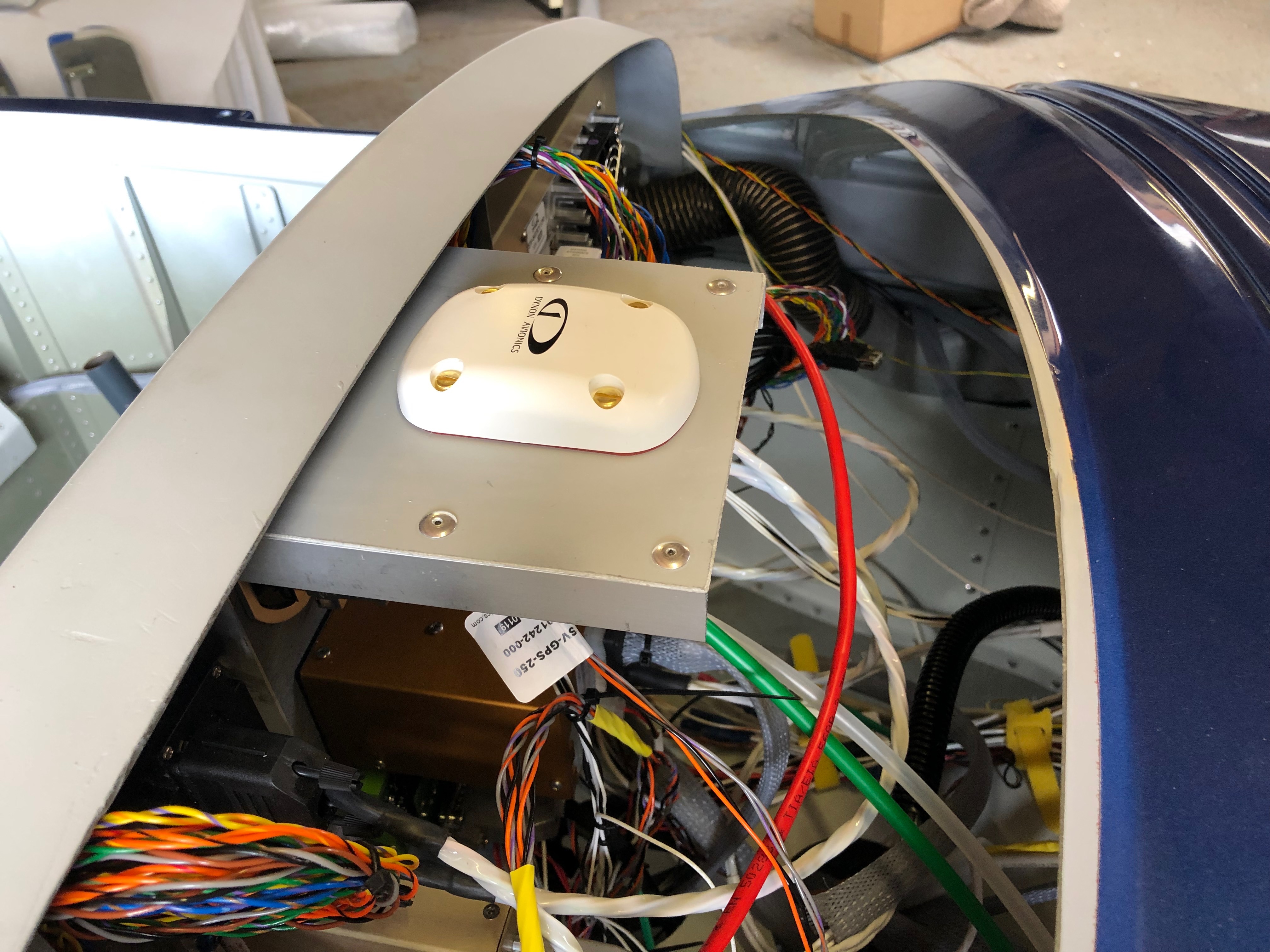
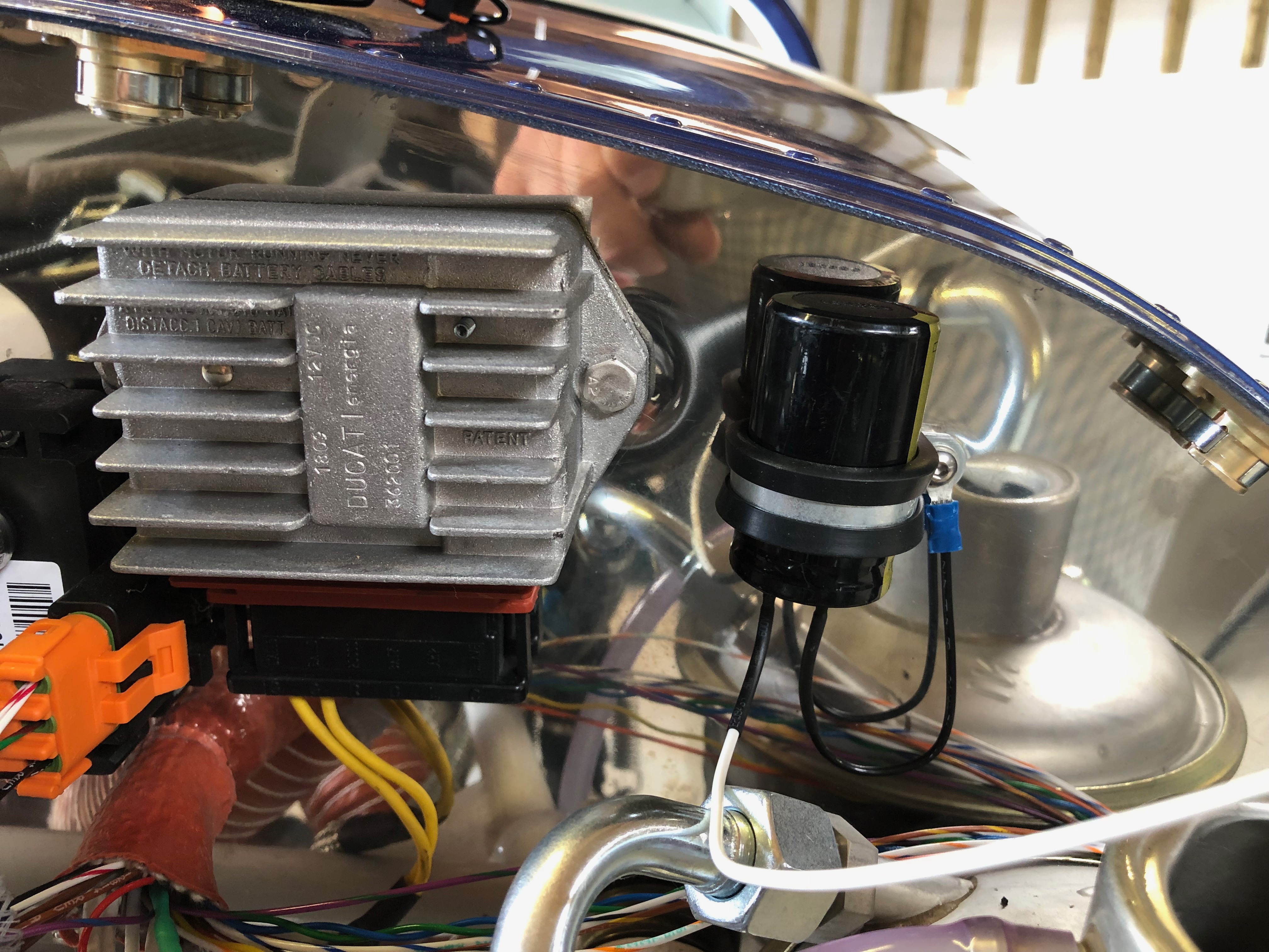
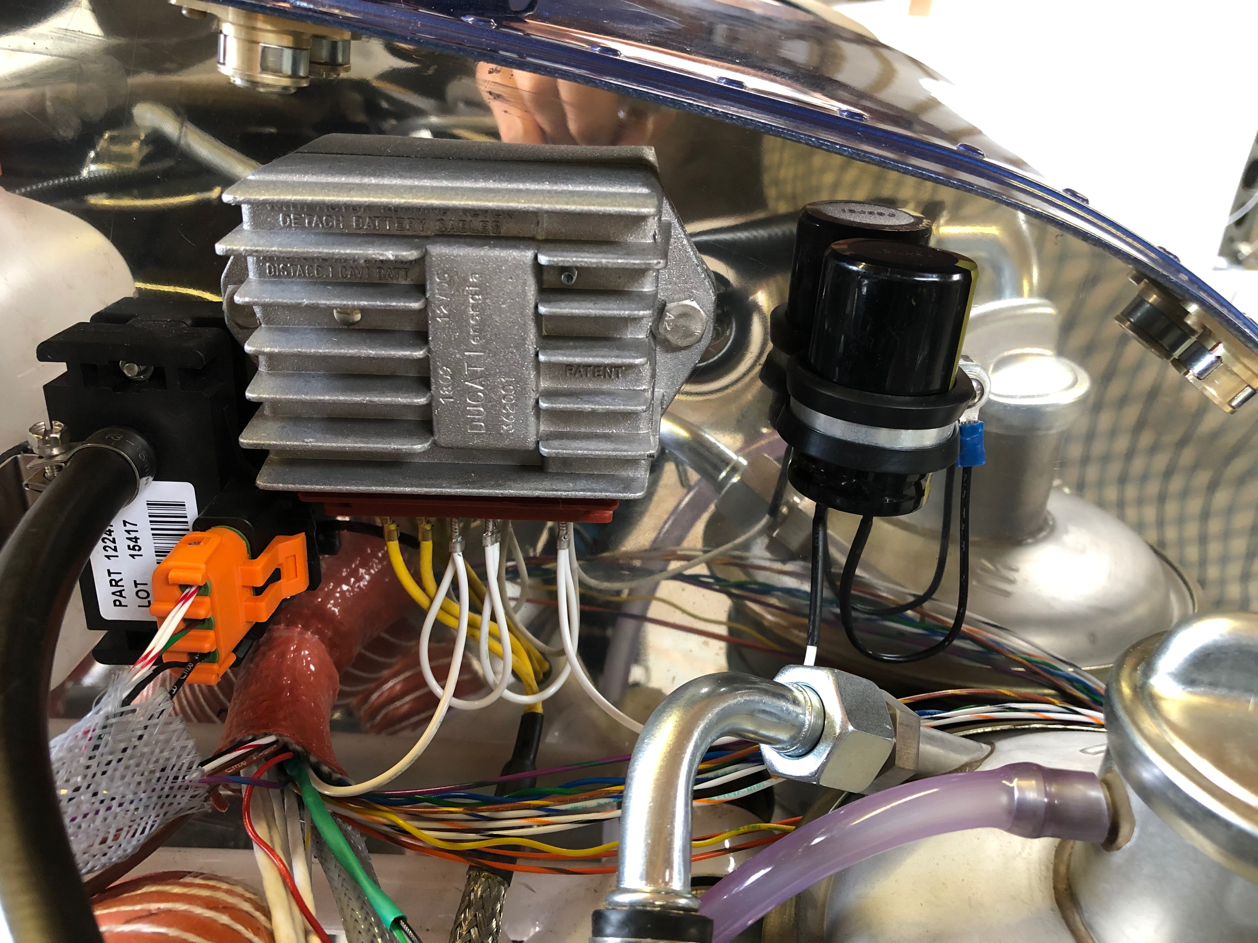
To give me a break from wiring I thought I’d start with a job that included some wiring after I finished it! Installing the GPS unit. Then back to wiring, first the charge circuit and then onto the the control sticks which includes the trim, radio and autopilot functions.

I decided to make a bracket out of some aluminium angle that could be fixed to the strengthening that I added to the rear of the panel.
After cutting 2 pieces 15 cm long I riveted a piece of the offcuts from the panel to use as a surface to mount the unit.
The mount works well but unfortunately there really isn’t any other place for the GPS so it will sit on this mount under the glare shield.
Next up is installing the wiring for the charge circuit. It requires a large capacitor that smoothes the output and protects the regulator unit from overcorrect spikes..
The completed charge circuit. It’s simpler then circuit diagrams make out.
I decided to get new Ray Allen control stick grips which are an enhancement on those supplied with the kit. They have 7 buttons instead of 5. The stick wiring requires 8 wires to be run down the control stick and onto various contacts. 4 are for the trim up, down, left and right, 1 is for ground, 1 for PTT and the other two are for whatever you want to use them for. I’ve decided to use one for autopilot disconnect and the other for the autopilot ‘Level’ function.