Dynon screens have the ability to display traffic if a suitable receiver is connected. Having looked at the receivers with the ability to output a suitable data stream Pilotaware’s Rosetta device looked to be the best bet. It receives ADSB, Flarm (via the OGN and P3i), Mode S/3D (via 360Radar, A & C transponders and of course other PilotAware equipped aircraft.
It’s a Raspberry Pi so the USB ports can be configured to output a data stream that contains the information that the device has received. So having researched what can be done I decided to carry out a permanent installation with an aviation grade installation kit with aerials mounted on the underside of the aircraft.
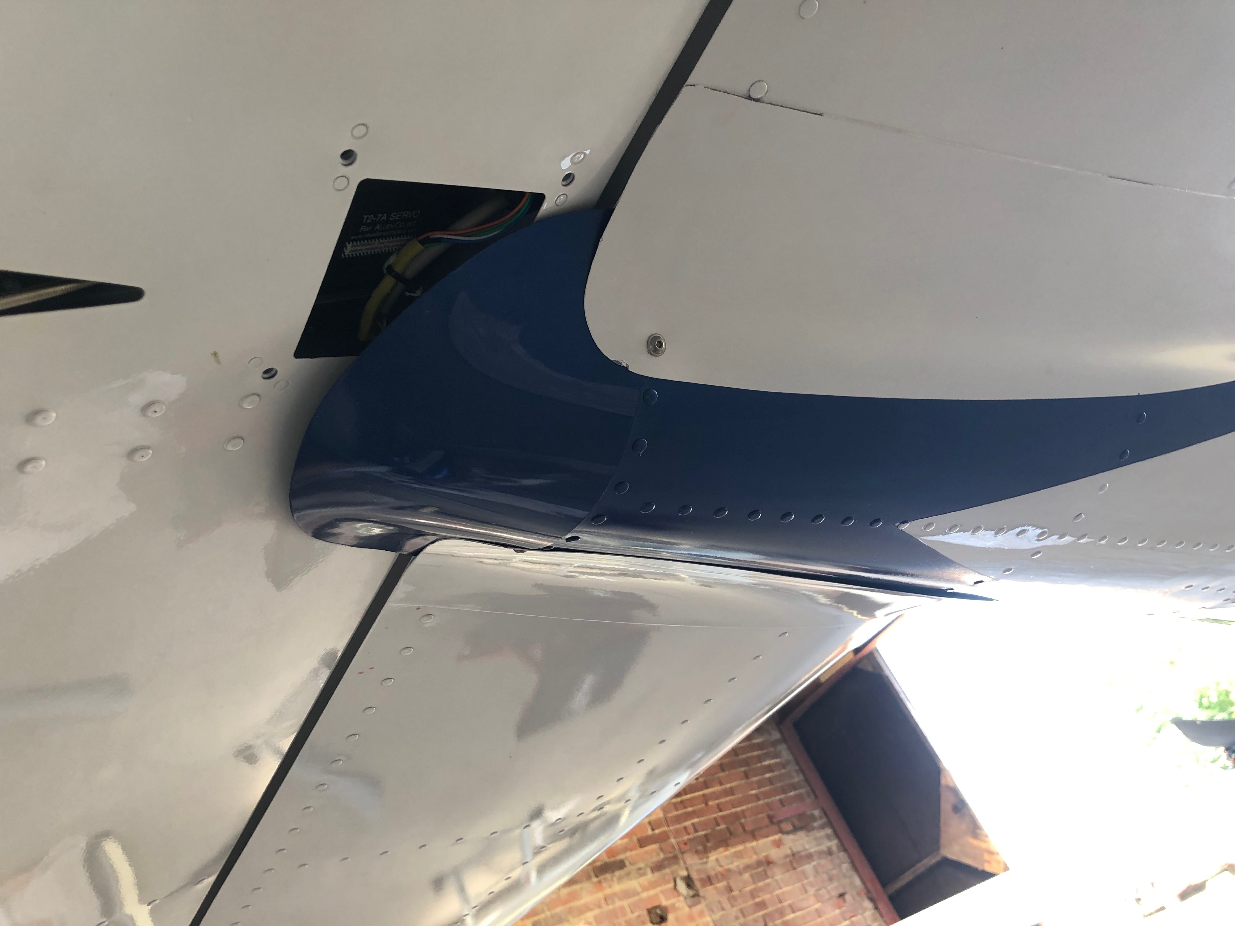
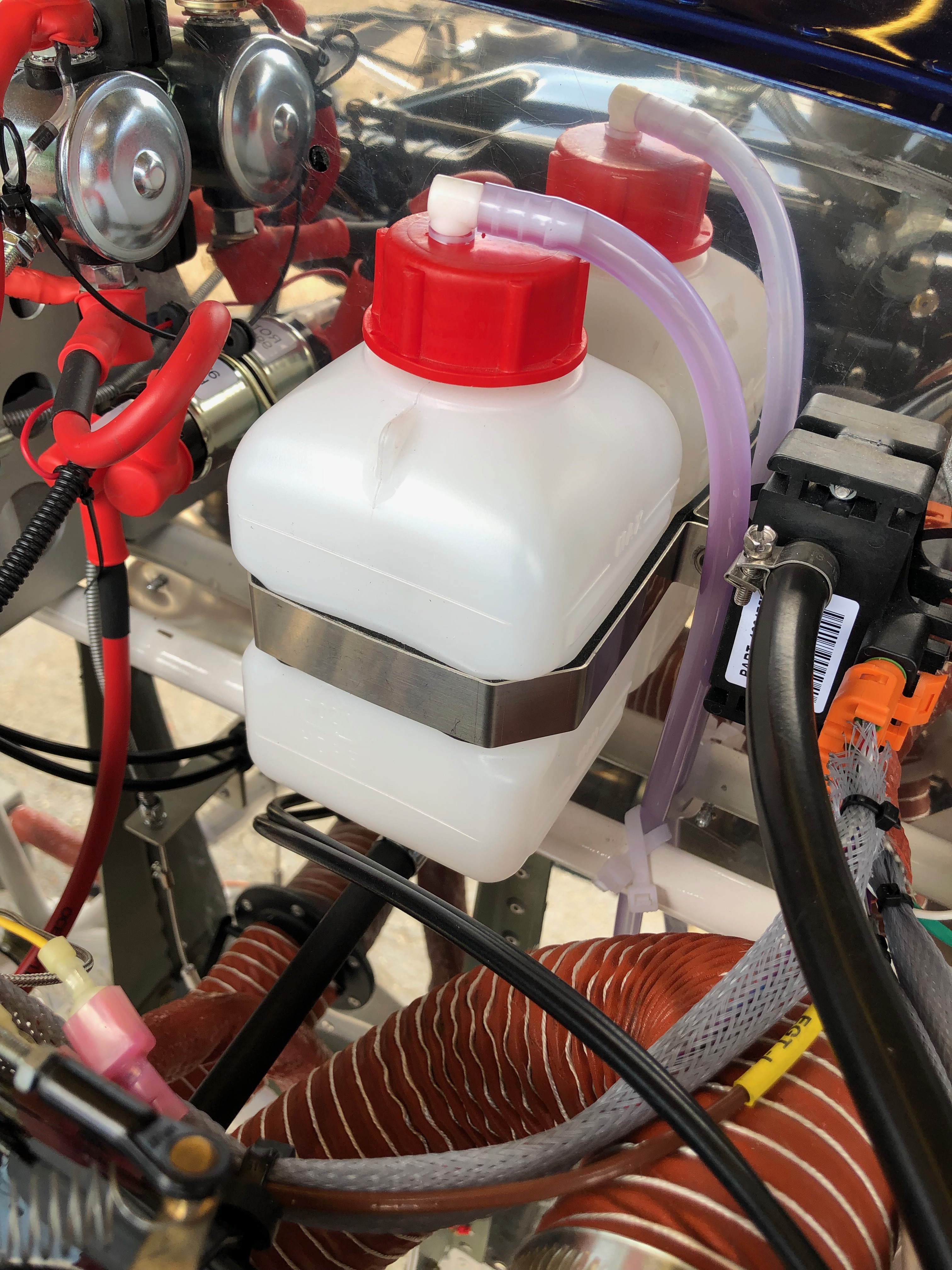
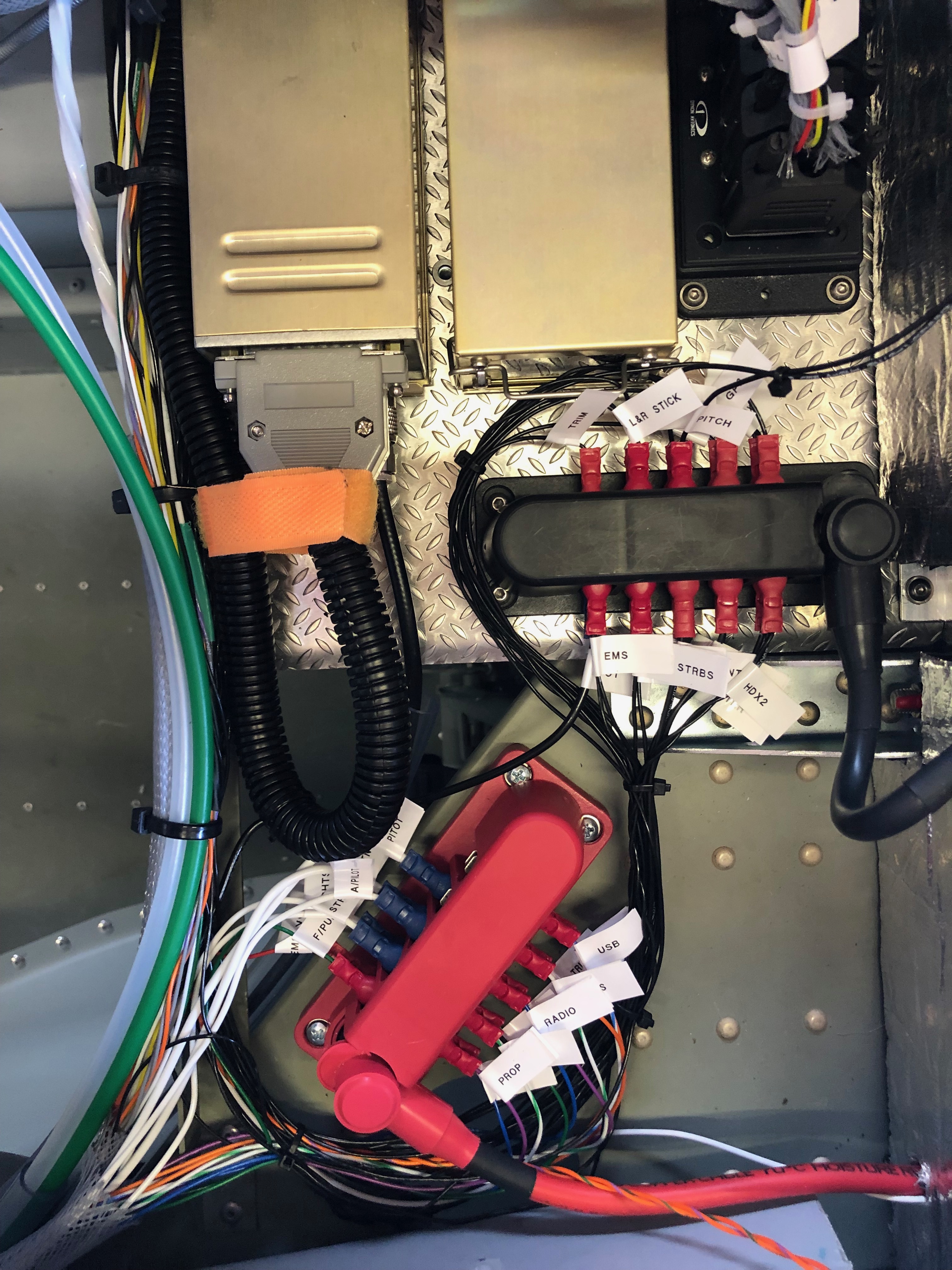
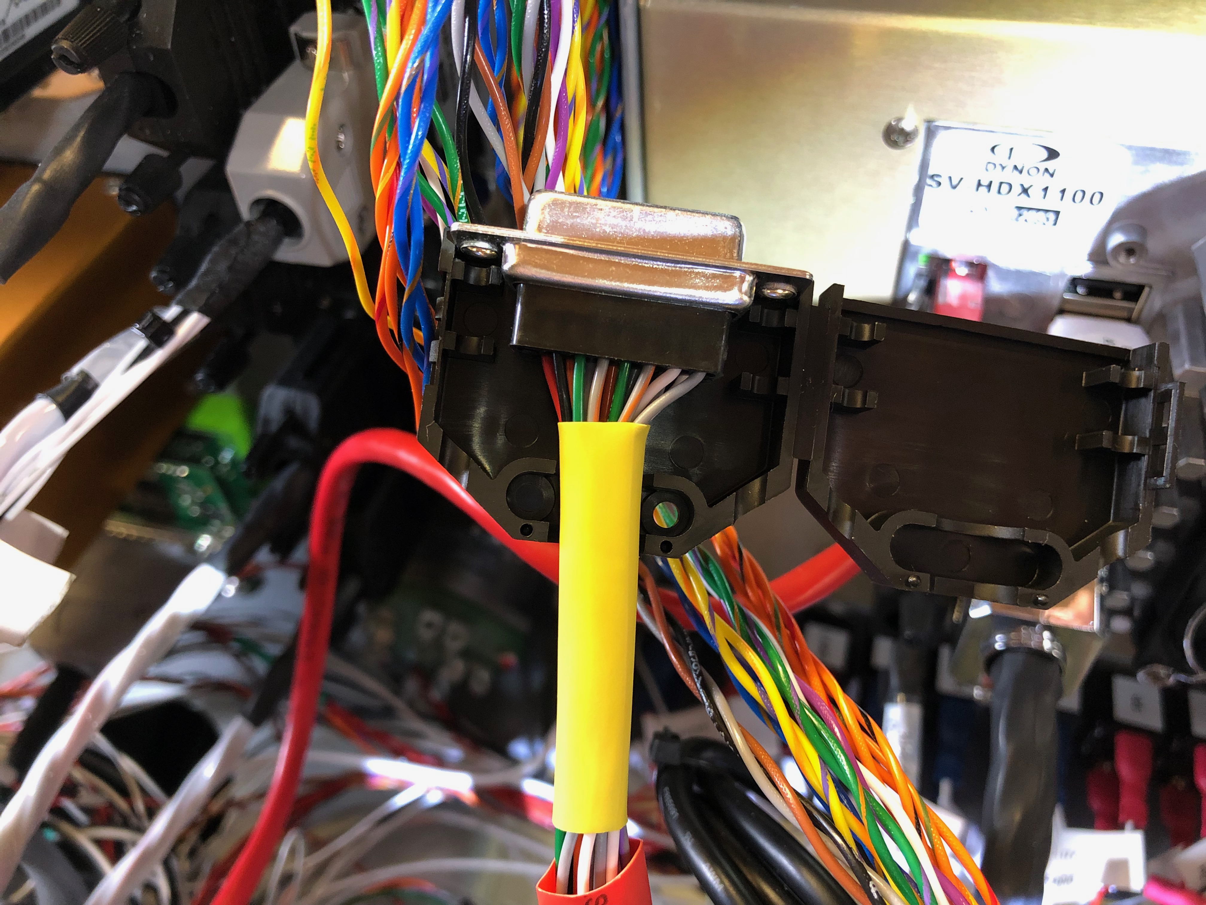
One of the first challenges was to work out where to put the Rosetta unit. If I had of thought of installing the unit earlier then I could have included it whilst building the aircraft… hindsight is a wonderful thing! Luckily I had space on the rear of the firewall which would work well. The Rosetta case has a number of attachment points including a photographic screw mount. I had a spare camera mount screw which happened to be just the right length so I use that to mount the unit. The cable ties are used to keep the power cable in position.Angling the unit down slightly allowed me to run the aerial coax cables from the unit and down the starboard side of the aircraft behind the interior trim to where I plan to put the aerials. I powered the unit from the Pilots Skyview screen USB so as soon as I power the Skyview it powers the Rosetta unit. It’s a neat solution.With a permanent installation the Rosetta GPS module normally enclosed within the case is removed and replaced with a GPS mouse on a long lead that plugs into the same USB port. The mouse can be run to a suitable point for the best reception. As I had already mounted the Dynon GPS250 unit on a platform just under the glare shield I decided to place the GPS mouse alongside. Another option is to use the Dynon GPS output and feed it into the Rosetta unit but I decided that I would use the Rosetta GPS as it removes the Dynon GPS as a single point of failure. Although the only option was to mount the aerials on the bottom of the aircraft I carefully considered where to place the two aerials to reduce any possible interference from the Transponder aerial. I decided to mount the ‘receive’ aerial on the starboard side adjacent to the main gear diagonally as far as practical from the transponder aerial. The ‘P3i’ aerial was mounted inline but in front of the Transponder aerial. This should reduce any interference and maximise the effectiveness of the PilotAware transmission. I used a USB to RS232 adapter lead plugged into USB port 3 which was configured to Flarm Traffic at an 115200 baud rate. I used port 4 of the Skyview configured for Flarm at the same baud rate and made up a D9 connector with data pins 2&3 reversed to interface with the adapter lead. As I’ve used the Skyview screen to power the Rosetta unit I didn’t need to connect a separate earth. Quite useful…Once installed it was time to test the unit. Switching the Skyview on powers the Rosetta unit which then transmits a WiFi network. Connecting an iPhone to the WiFI and pointing the browser to 192.168.1.1 displays a configuration screen. Once the config is set a ‘Traffic’ button on the webpage displays what the unit is receiving. As you can see it receives a lot of traffic. This list is not filtered so shows traffic at all levels.Another button on the webpage is labelled ‘Radar’ and displays this screen. The onscreen buttons allows you to change the altitude and range of the contacts displayed. This screen is set to the maximum. It shows the contacts, height, climb or descent and track. The colour of the diamonds depict the ‘threat’ of the contact. These screens are interesting but the data is much more useful when you feed it into an app like SkyDemon, EasyVFR or display it on the Skyview panels. This is how the traffic is displayed on the Skyview map. Again the data is unfiltered so shows traffic that would be of no use or threat to me so I’ll filter those out some point in the future. The Skyview shows the altitude, whether climb or descending and track of the traffic. Aircraft over 10,000 ft have a ‘+99’ label.Synthetic vision really ups the game with traffic showing as targets in front of you. Any that are a threat will be coloured appropriately and audible warnings given via the headset.
All in all I’m really pleased with the installation and it was well worth the time invested especially as Maypole’s runway is still out of action due to water logging so used the time productively.
The systems I have installed can lure you into keeping your head down and eyes in the cockpit, however it is essential to keep your head up and carry out an effective look out as not all aircraft have conspicuity systems onboard. These systems help you avoid conflict but must be used in conjunction with the No. 1 system, your eyes!
Since my first solo flight in G-MLSY on the 22nd November I’ve managed to log around 9 hours in 15 flights. The weather has been kind and quite dry. All of them have been used to familiarise myself with the aircraft and understand the flight characteristics and systems. It’s a delight to fly, reasonably fast and very responsive.
MLSY looking very sleek with her spats on.The Kent coast is lovely to fly round. Herne Bay pier
One of the things I needed to do was tune the autopilot. So where shall I go? I thought a little message to Karen would be very appropriate after all the support and encouragement she’s given me during the build so I programmed this up on SkyDemon and sent it to the SkyView.
Once I had taken off I engaged the autopilot and let it do the rest. I adjusted a few autopilot settings during the flight but it worked faultlessly. It’s a very impressive set up.
This flight can be seen on FlightRadar24 by searching for G-MLSY on 3rd December.Flying the route round the heart.
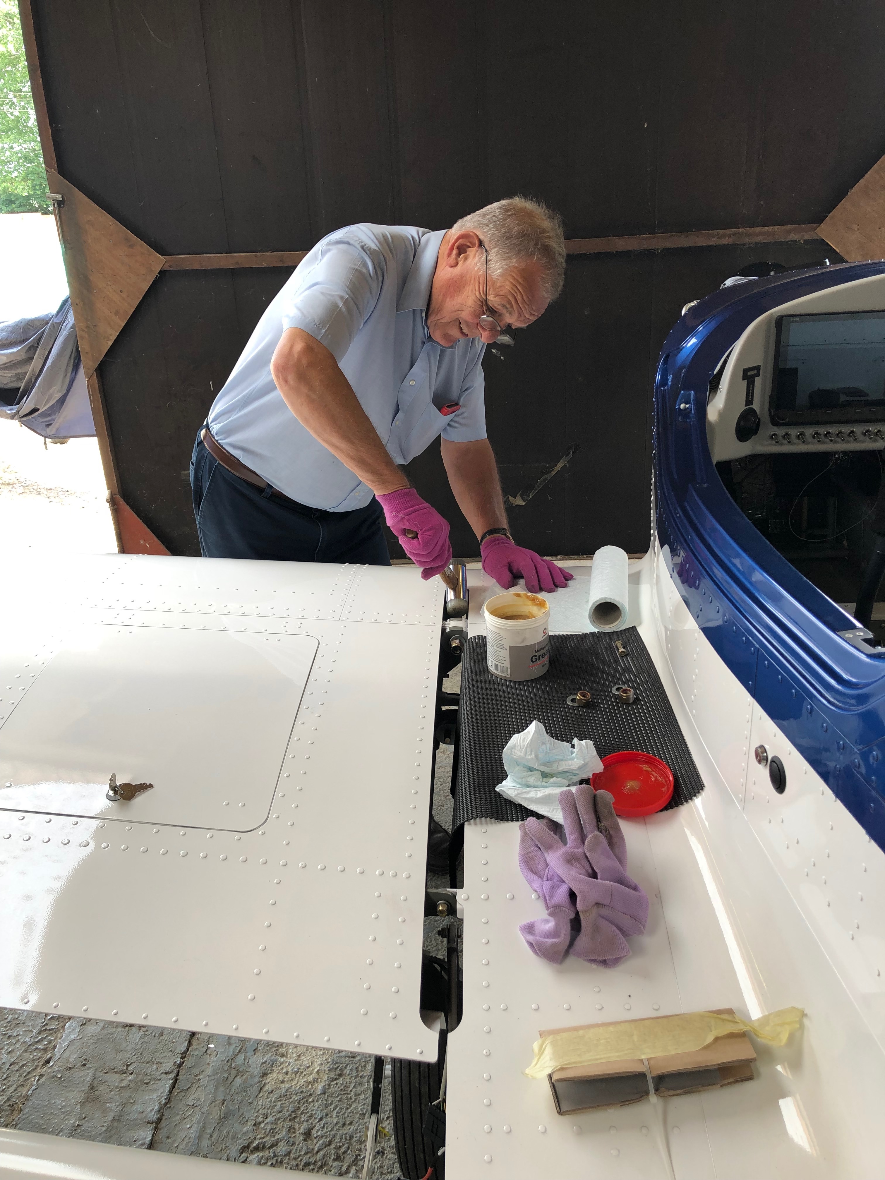
With only a few things left to do one of them is to set the control surface deflections. On the face of it, it’s an easy job but it requires a differential movement from fully up to fully down. Due to that specification there’s more than one place to adjust. It requires a bit of juggling to get it right and in the heat of Thursday it wasn’t the day to do it.
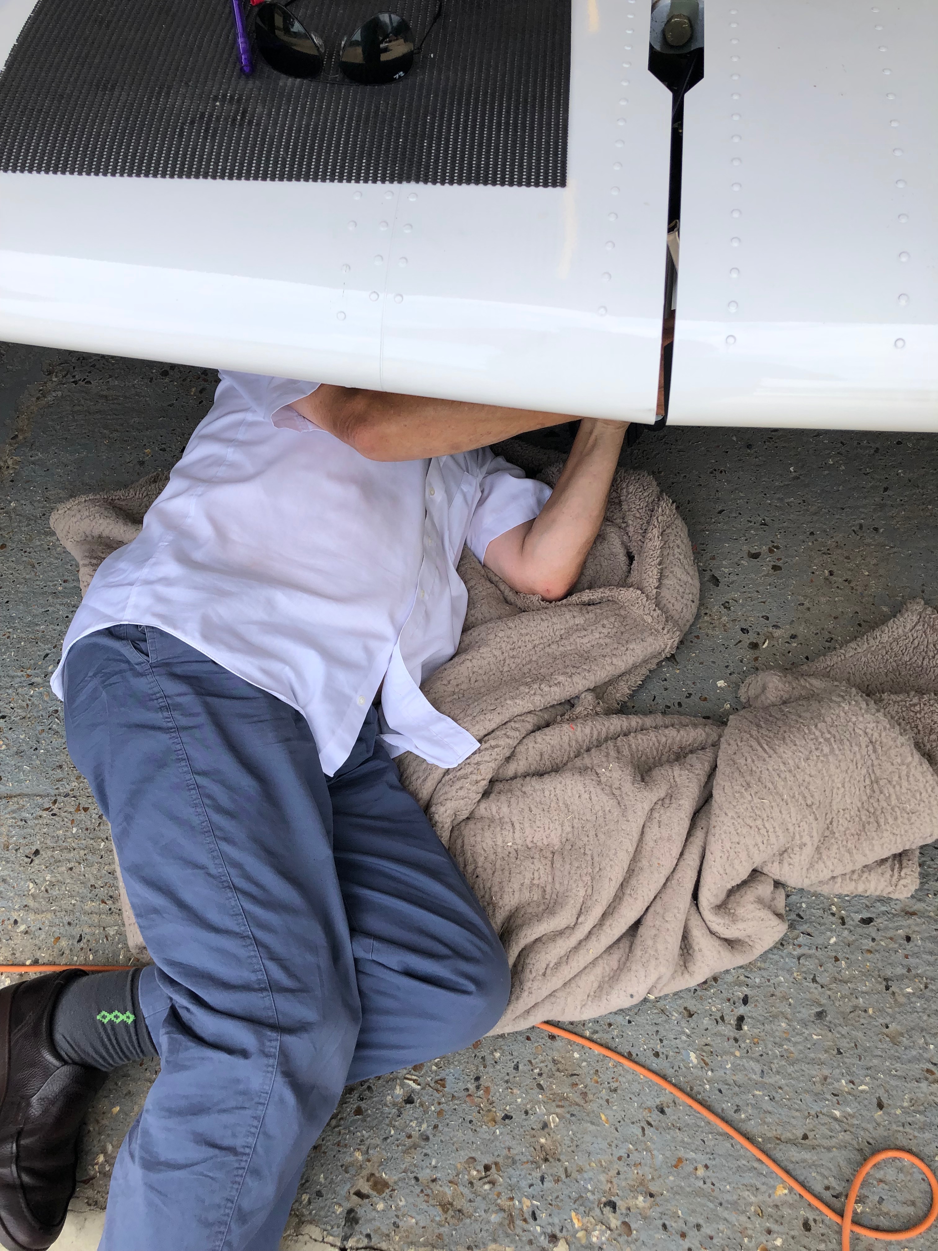
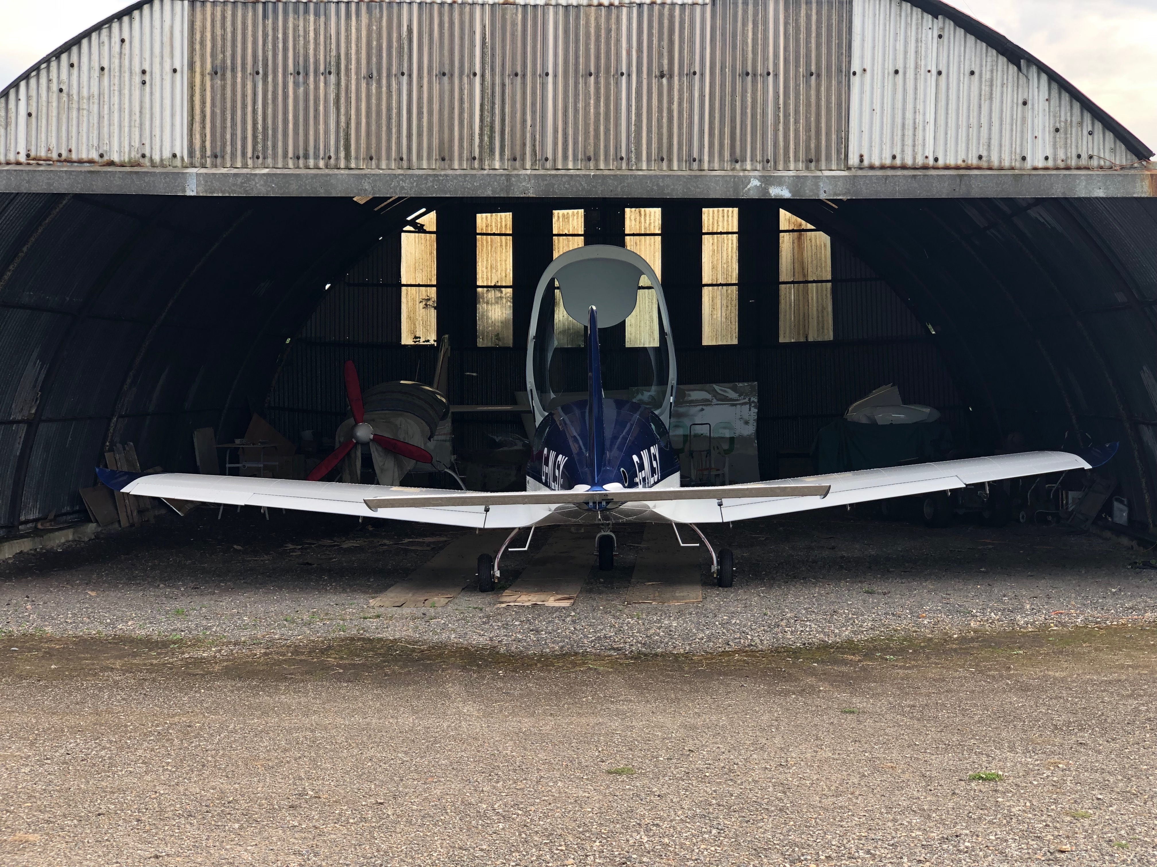
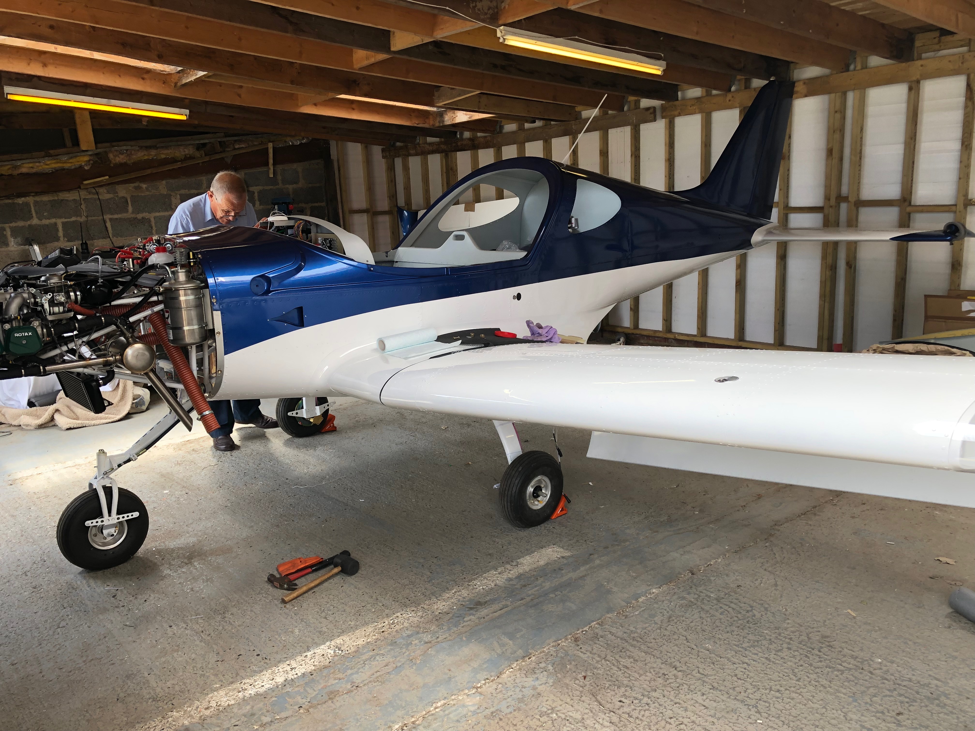
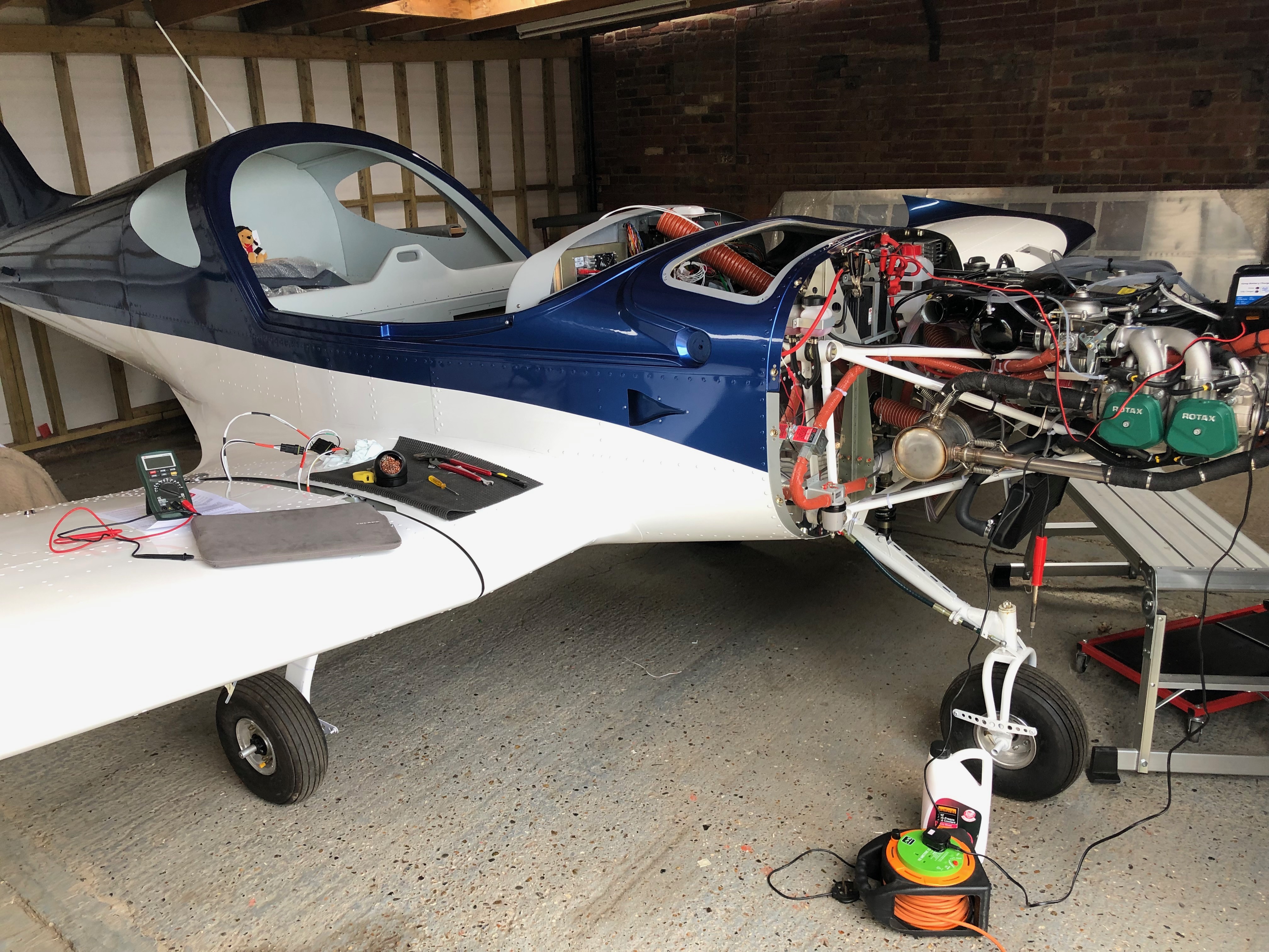
One of the adjustment points in in the rear of the aircraft with a very small inspection panel to undo nuts and make the adjustment. It was very tricky and time-consuming but got there in the end. I used an iPhone inbuilt app for the level that was then checked by Ian who has a digital protractor. Amazingly the iPhone reading match Ian’s readings +30 deg -15 deg.Ian came round to ask if I wanted to run the engine today as he’s away Monday and Tuesday. With the temperatures very much lower today it seemed a good idea so we got on with checking everything was ok before taking it out of the workshop.The workshop ceiling was far too low to fit the canopy so needed to do it once it was out. It took a lot of jiggling to get it out of the workshop and now it’s out it won’t be going back in! Out on the grass away from all the stones and Pete Sharpe recording the event on my iPhone it’s time to do a final check before the first start. The electric fuel pump was switched on to check for leaks from the fuel system, all seems ok. First time in the cockpit for real so another good check to make sure every thing is working as expected. Ian is standing by just in case anything goes wrong with a radio and fire extinguisher!Canopy down, calling “CLEAR PROP” as I turn the ignition key and my baby burst into life on the very first turn – I can only shake my head in disbelief – Amazing!Watching the Ts&Ps as the engine is running Ian does a walk round to check for any obvious problems but there aren’t any. It’s running as sweet as a nut.After being told to smile I look up as one happy chappy… Ian prompted me to taxy the aircraft to spread the noise about a bit so I did a few runs up and down the runway checking brakes, steering, instruments, pitot system and then power checks. All very good apart from the flys on the firewall. Ian carried out a further check once the engine had stopped but all was ok and there were no problems.A very empty workshop. It seemed big enough when I first started but as time went on it proved to be too small to house the aircraft on a permanent basis.So this is where G-MLSY will be for the weekend before being moved to its new position in the main hanger.
Today I finished off the fuel tank calibrations and Ian did some inspections and sign offs so I could add some trim and send some paperwork to the LAA.
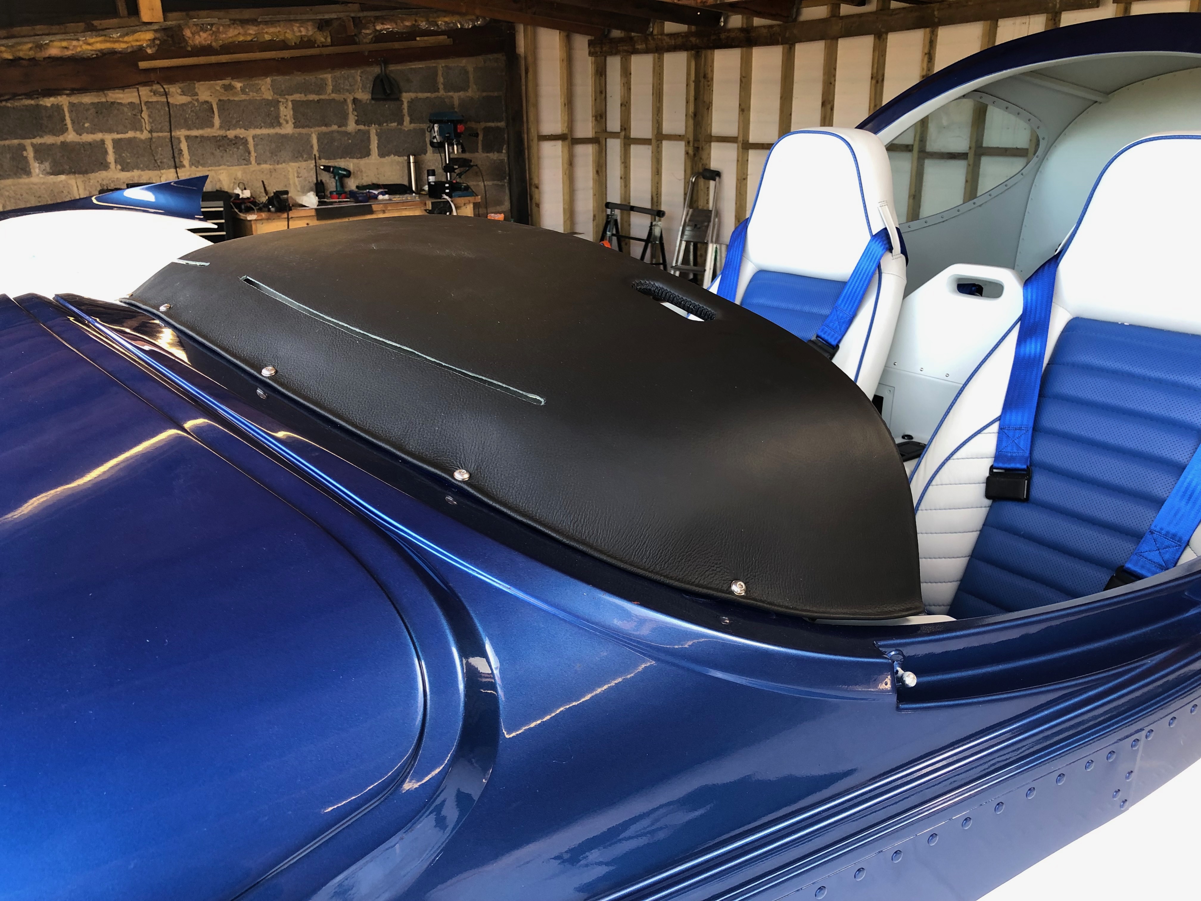
Starting again with the calibration screen,I repeated the method described yesterday but the battery went flat as it had been run the night before for quite some time but I’d forgotten to turn the batter charger on. So I lost the calibrations., which meant…I had to drain the tanks and start again but on the second run the third fuel add didn’t register so I had to drain the tank and start again. I’m not sure if by this time the heat was getting to me as it was up in the 30s by this time with the sun blazing into the workshop. Luckily the third attempt went well and the I managed to finish off the calibration – thank god…I’ve added a couple of trims to the rear of the plane. First the top……and then the bottom. The trim motor cover will be added after we’ve done all the control surface checked.Last on the agenda today is to fit the glare shield as I won’t need to take that off again as all the electric have been checked and signed off.
Music: Gerry Cinnamon, Stereophonics, The Libertines
6 months to the day since I took delivery of G-MLSY and it’s coming to the end of the build… but I say that every day to be fair. The next major stage is the testing and lots of paperwork to do and approvals to gain before it can fly.
A few people have dropped by to view how I’m doing and some have sent messages. All I can say is “Thanks”. It’s been a bit like a marathon and the support from those that have taken the time to visit or send messages is very much welcomed and keeps my motivation topped up.
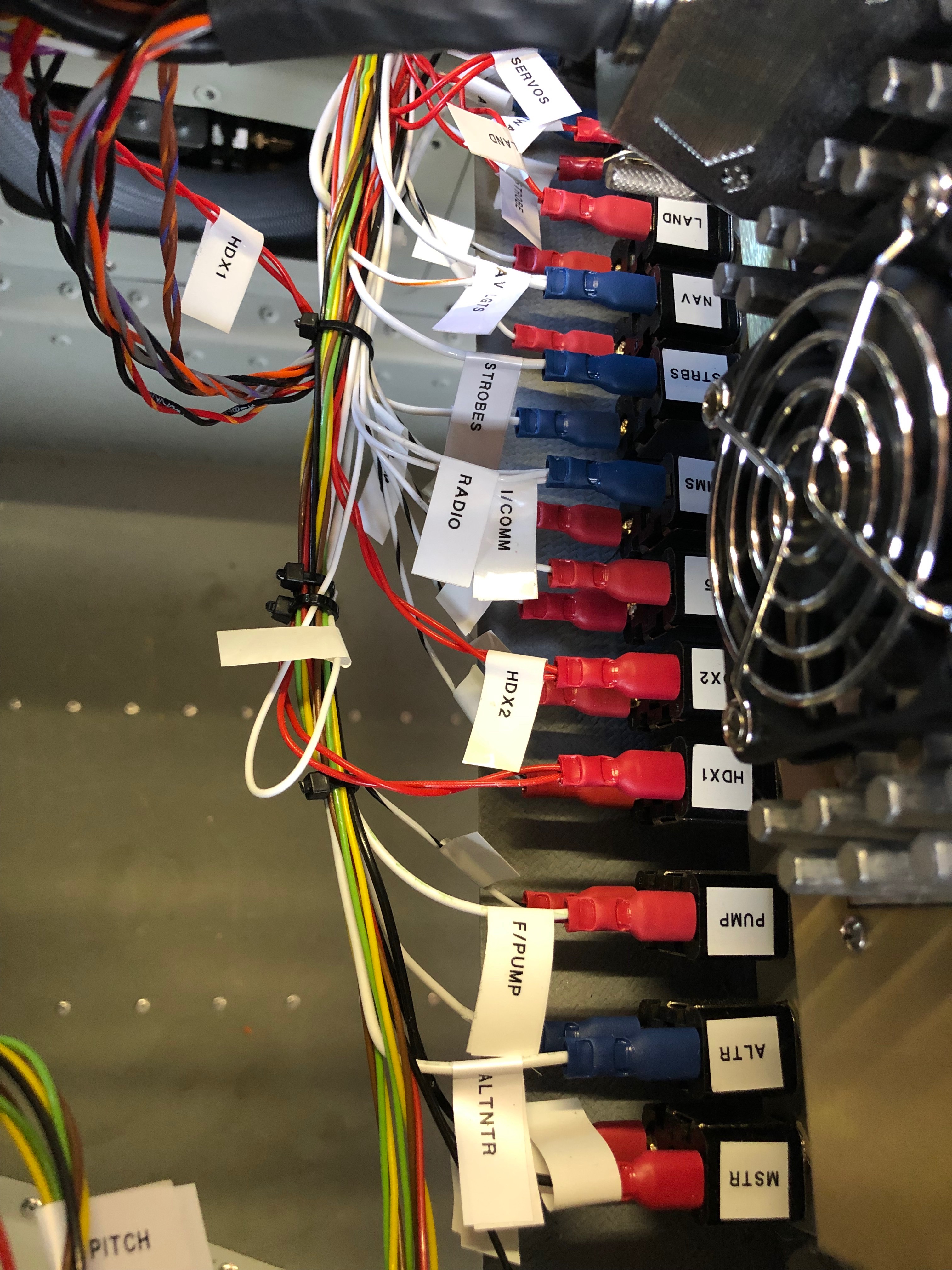
I’ve decided to use the light function on the switches so each switch require an earth lead to be attached to the third contact to enable the function. It required a bit of back tracking but was fairly easy to do. The wings need to come off again so Ian is called to action again helped by Pete Sharpe I need to run the fuel level sensor wiring in, polish the wings and apply the registration before refitting for the final time. When I arrived home the stainless steel ID plate and Radio licence had arrived ticking off another couple of items from the list of Admin that accompanies the build.
Getting close to finishing now so some small outstanding jobs to do including wiring starter solenoid protection, a stuck starter indicator connection and external level button on each stick top hat. I also trial fitted the registration and polished the fuselage ready to apply it.
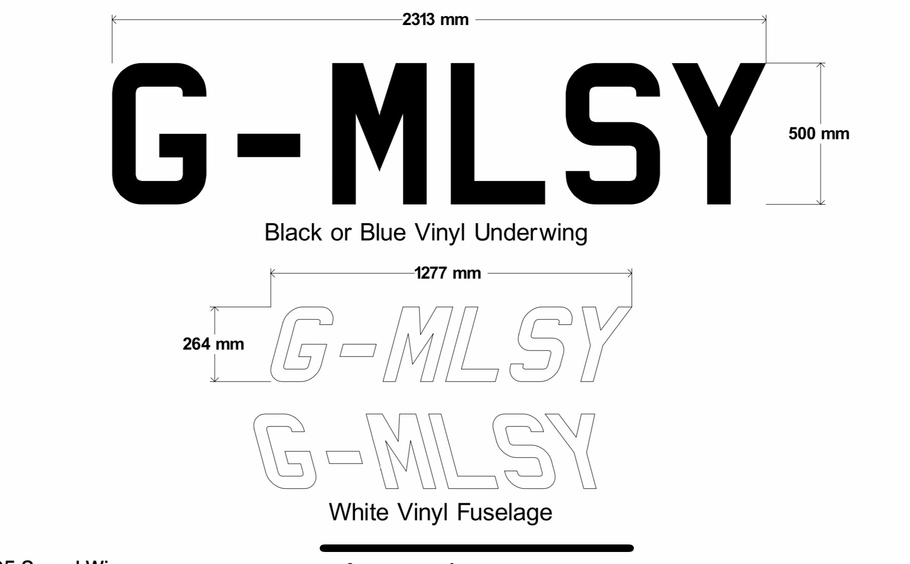
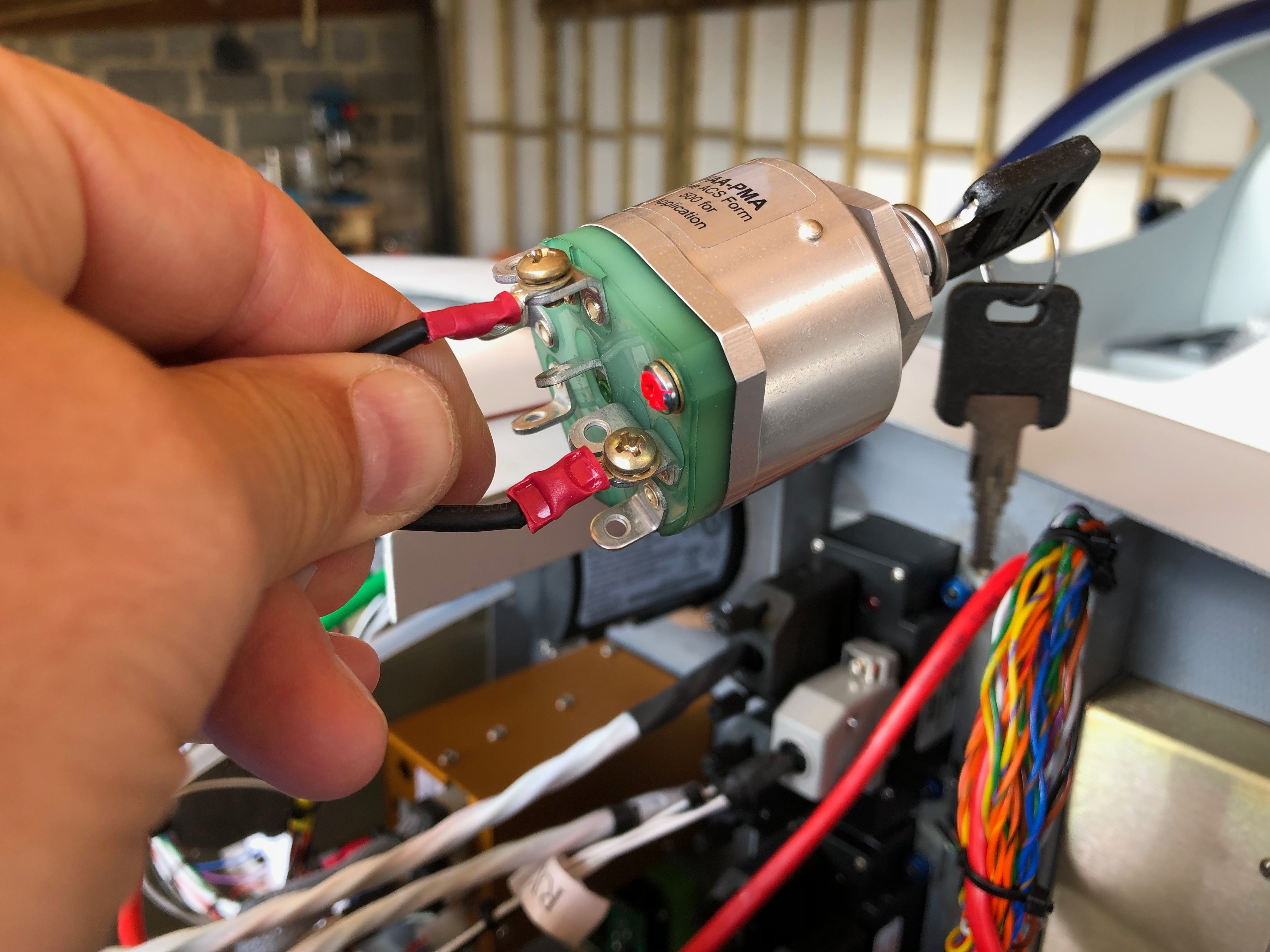
I received the registration vinyls on Friday so today I need to ready the fuselage for them to be applied. Just a case to working out the best placing for them. Along the line of paintwork line or along the rivet line? that’s the question!I’ve bought a polishing machine to make the job easier with some G6 cutting liquid cutting compound. It takes a bit of getting used to using it but it makes a good job it. The paintwork needs to be de-greased before I can apply the registration letters.When I sent the aircraft for spraying they noticed that one rivet hadn’t been squeezed on the trailing edge of the wing. So Ian brought his rivet squeezers in with a special head for this type of rivet. A little more wiring to do. A diode is placed from the starter solenoid to earth to kill any spikes caused from the contacts releasing when starting the engine. Also I’ve wired up a contact on the Dynon screens to that will show a ‘stuck starter’ situation. I was a little worried that a higher voltage may find it’s way back to the EFIS so I’ve protected the connection with a diode to prevent spikes and a 1 amp fuse.
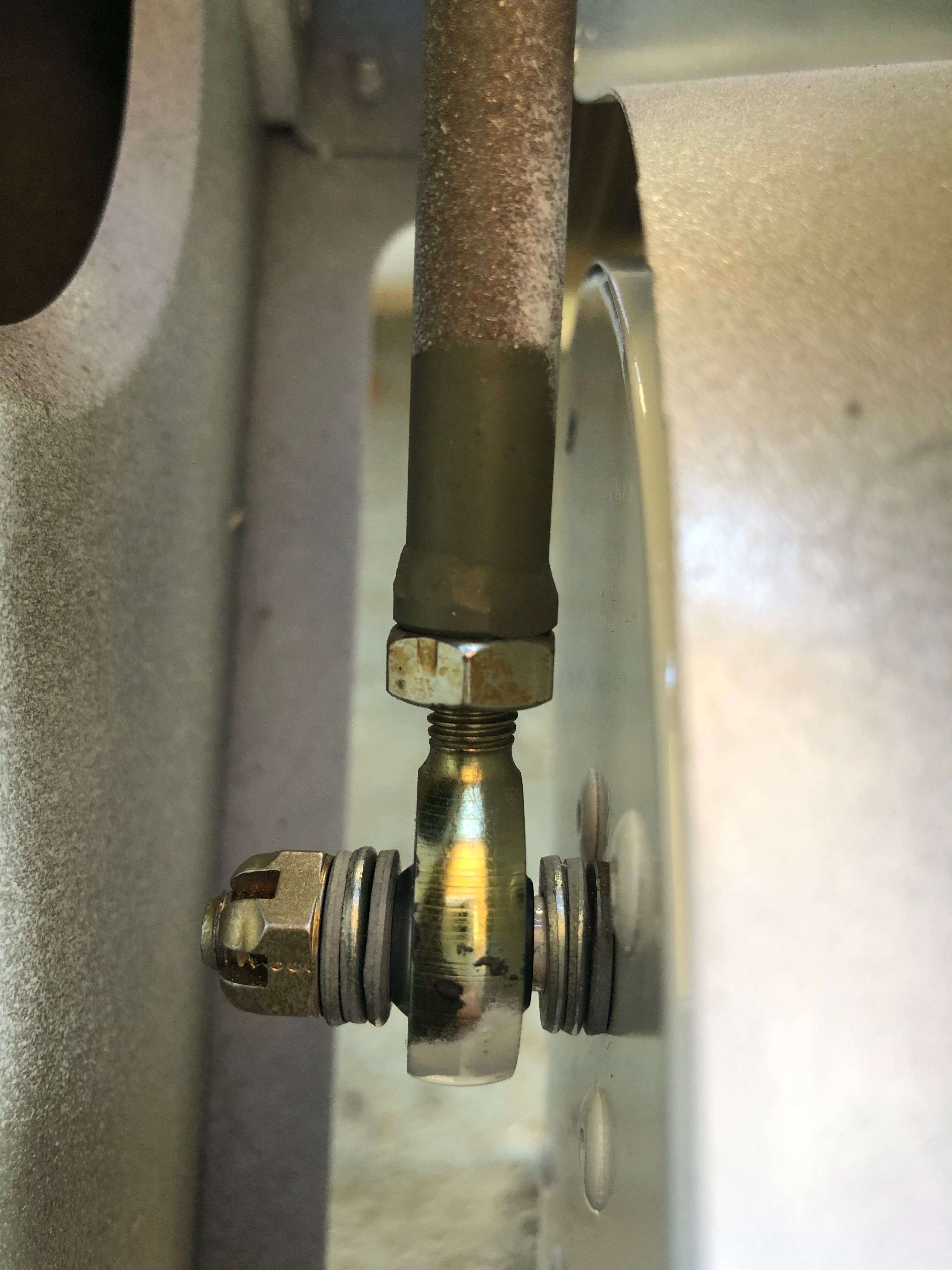
A short day today as I was hoping that the M18 x 1 die would be delivered today so I could do the work in the afternoon. Unfortunately for some reason it was delayed so will have to wait in for it tomorrow now. The leak has caused me a couple of days delay so far which is a little frustrating.
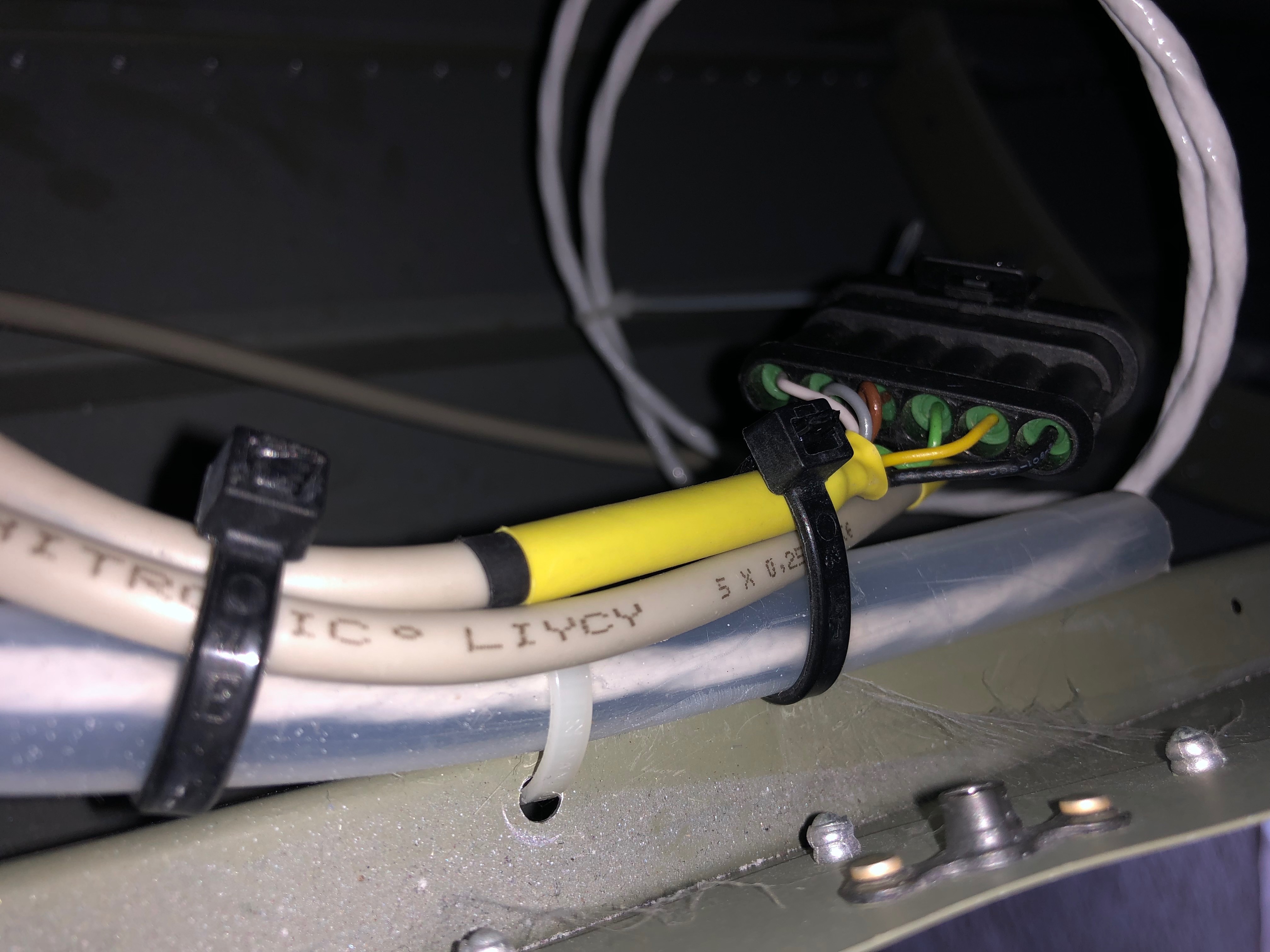
With the water pump dismantled I need to use a M18 x 1 die to cut further down the pipe to provide a better seal than achieved on the first fit. This is a revised method that has worked for others that have had this problem according to Bristell.The wires connecting the lights, strobes, trim motor and pitot in the wings need to be protected so a piece of flexible conduit is used.The elevator trim and lights connectors are secured to prevent them from moving in service.The artwork for the registration has been prepared and I’m obtaining a couple of quotes before ordering.
Music: Reverend And The Makers, Ian Brown and Razorlight.
A few smaller jobs to do today including the last bit of wiring, wire locking the tailplane, adding a vent pipe to the coolant bottle and adjusting the flap operating arms.
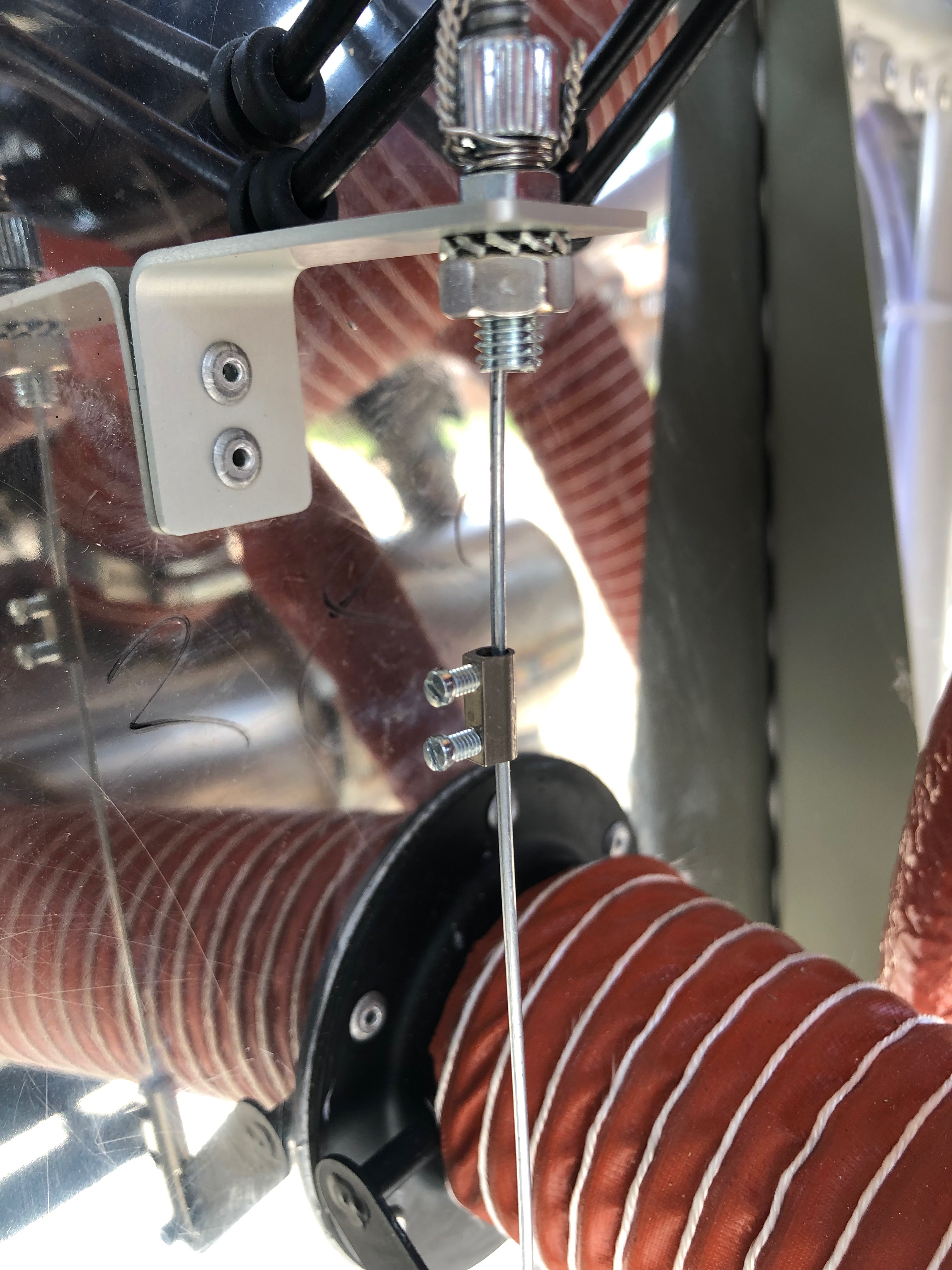
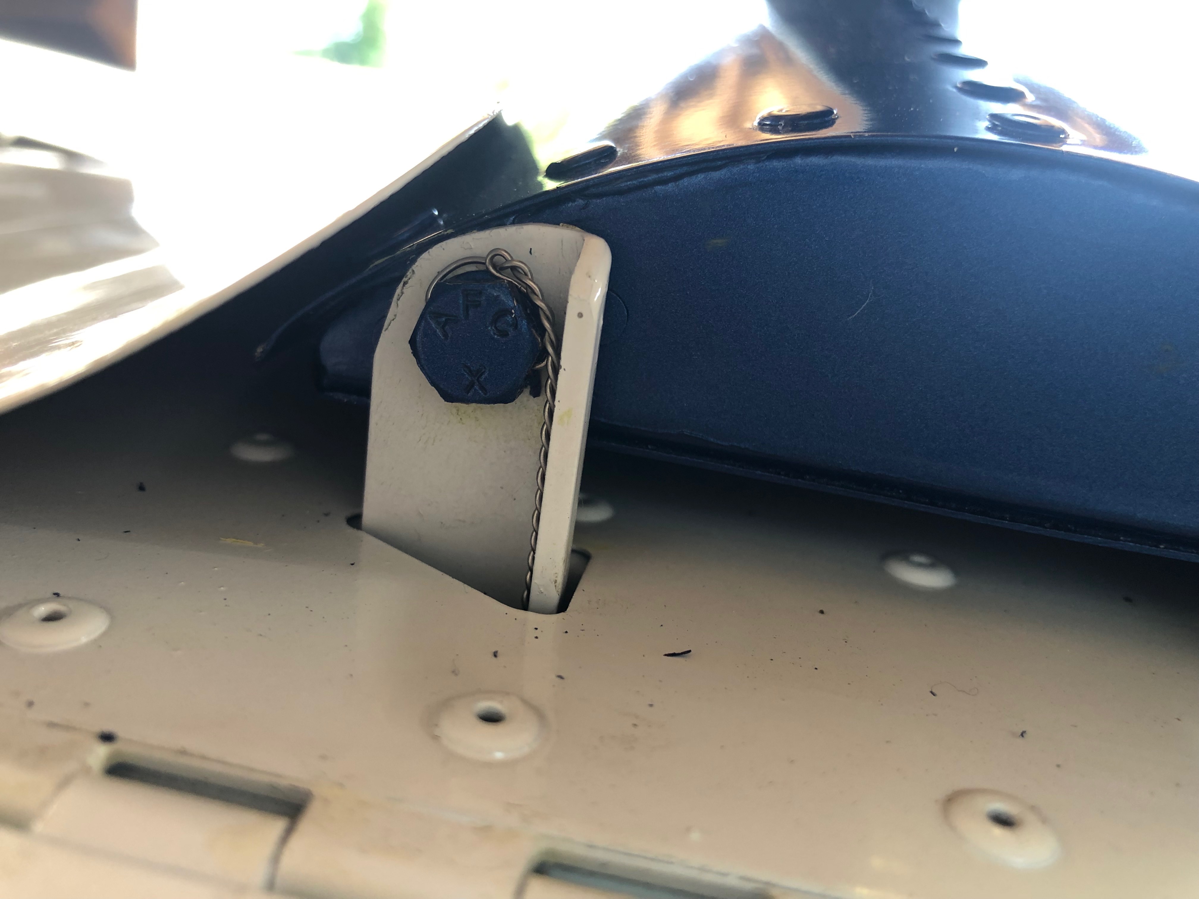
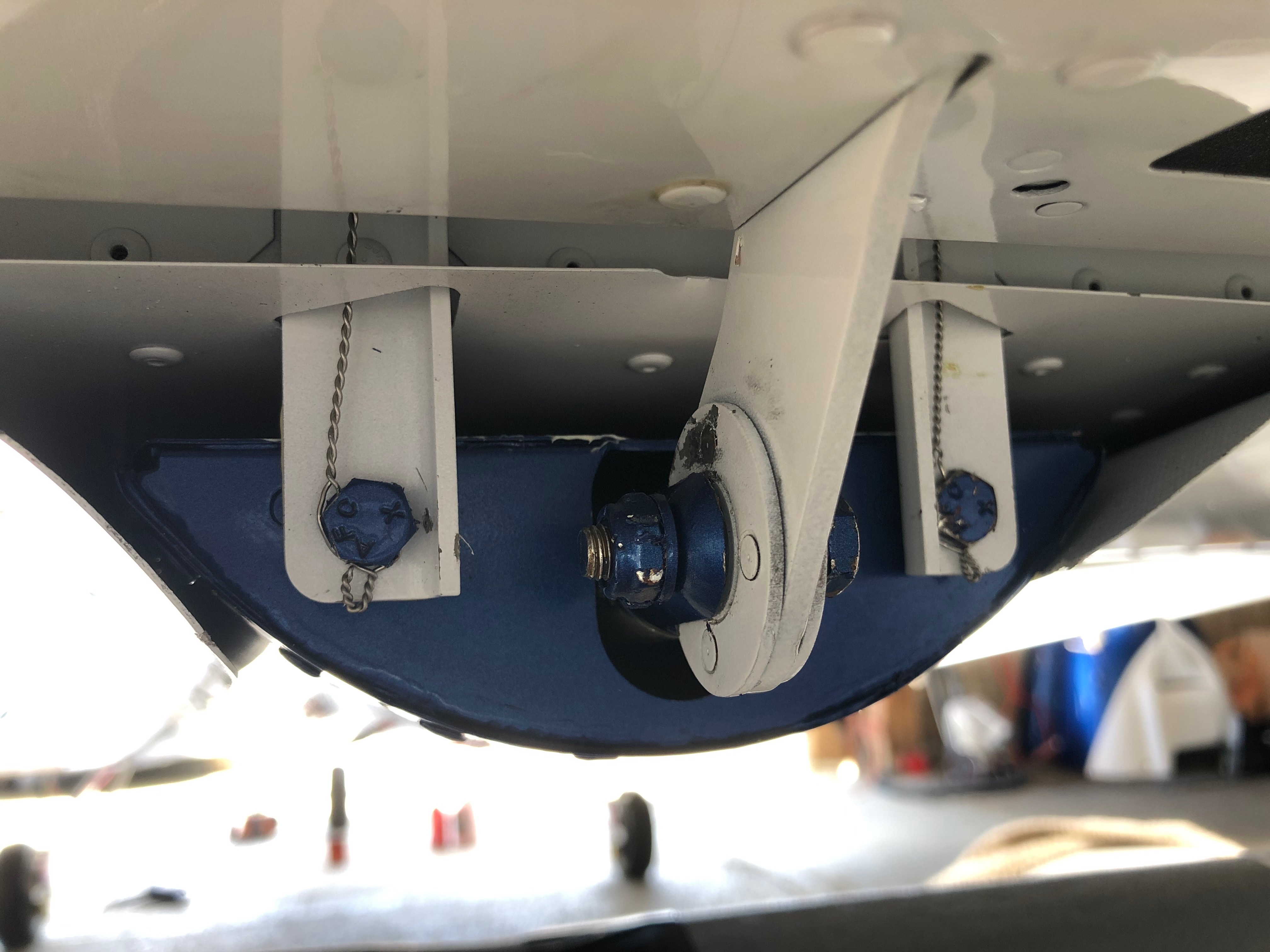
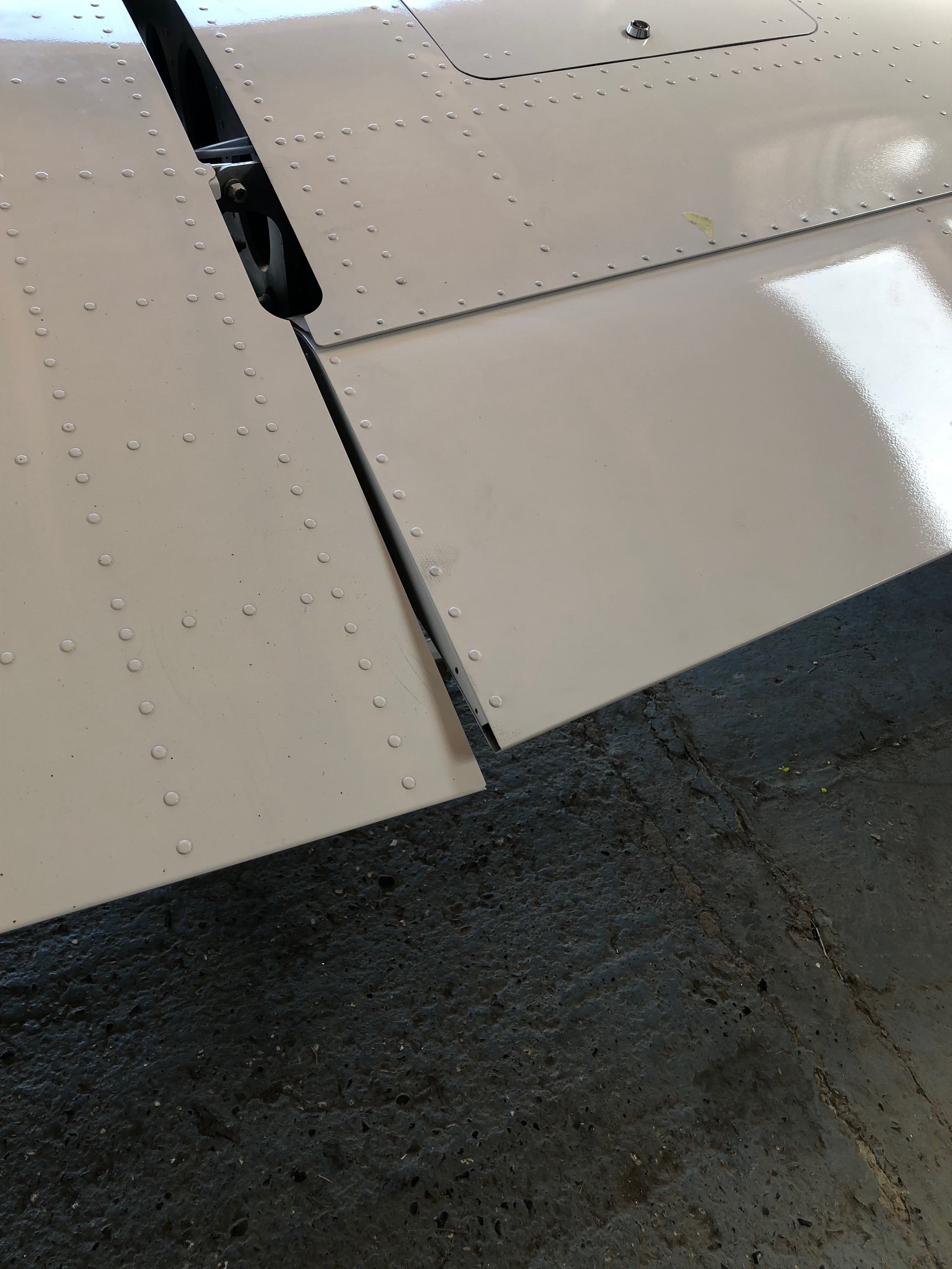
The ACS ignition switch requires 5 wires, Left and Right magnetos, battery, starter solenoid and ground. It uses 4mm ring connectors that are secured with screws and shake proof washers.The carb heat and heater controls require a positive stop to make sure you don’t pull the cable too far. I’ve used a ‘chocolate block’ with the insulation cut off……slid it on the cable and secured it with the 2 screws.The same was done for the heater control.I’ve added a breather in the coolant bootle and run the pipe down the firewall and out under the fuselage.Four bolts secure the tailplane and once torqued to the correct setting are wire locked to ensure they don’t undo.The wire locking is carried through from the top bolt and finished off around the bottom bolt.The flaps require adjusting to be flush with the trailing edge of the wing…The control rod arms have adjusters at either end and are adjusted equally before locking up.
it’s time to fit the wings so I need to add the connectors to the trim, landing lights and heated pitot looms that I have already run in. I’ve also run in the radio coax cable so need to terminate that and carry out a final tidying up of the wiring.
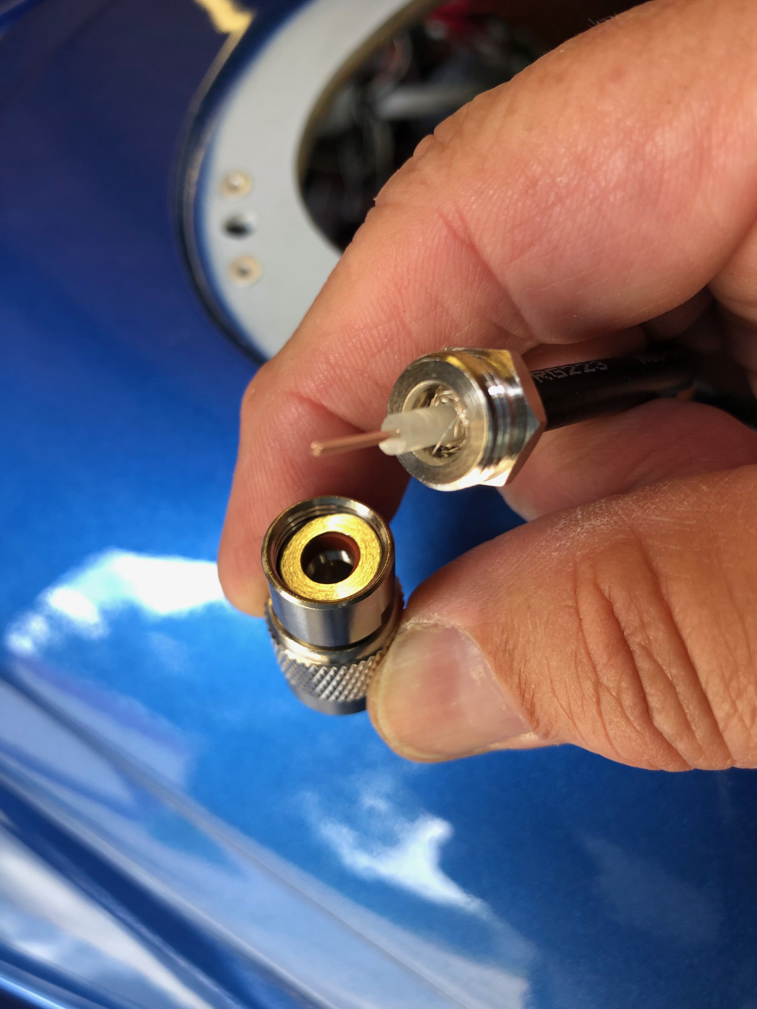
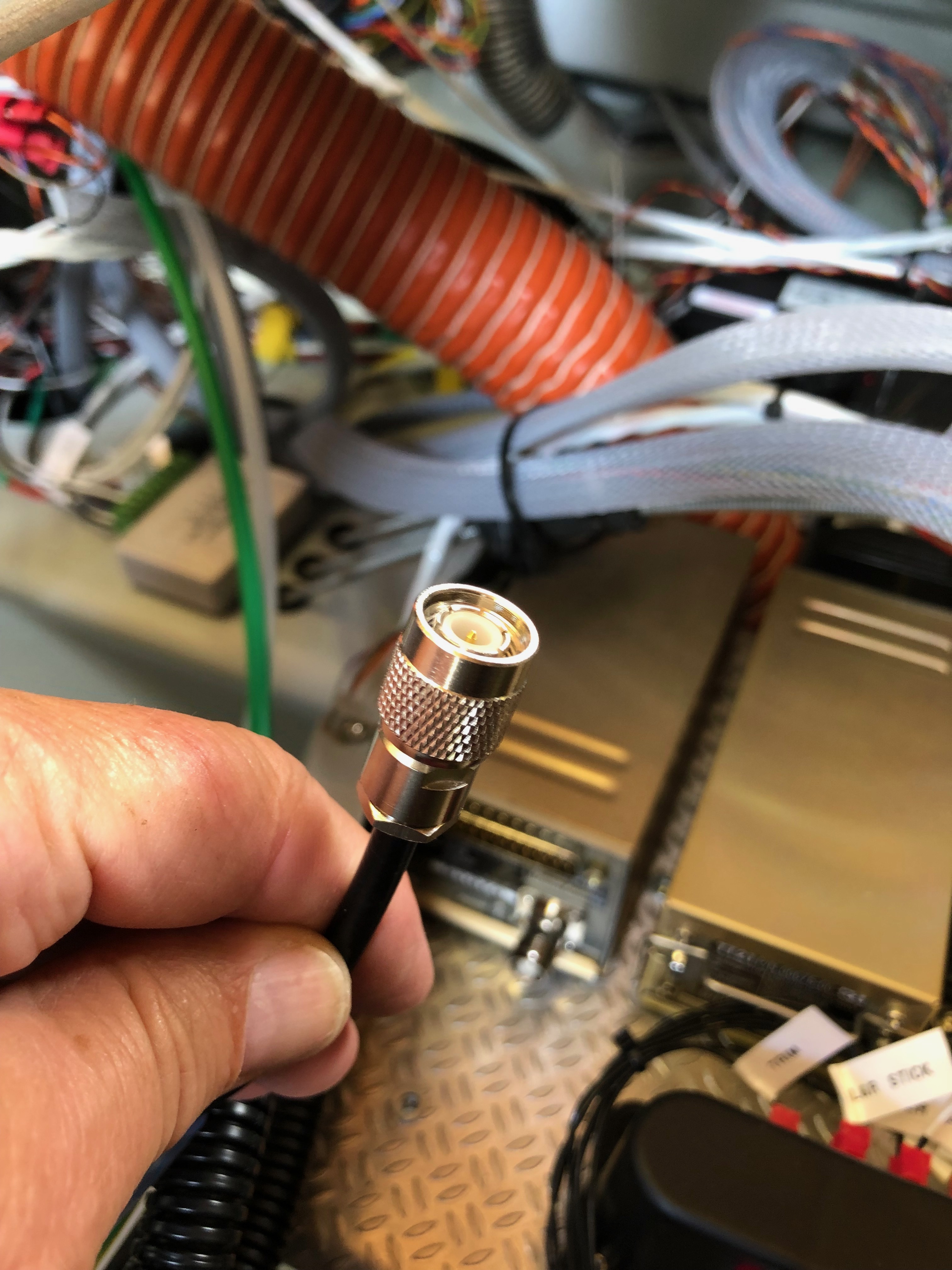
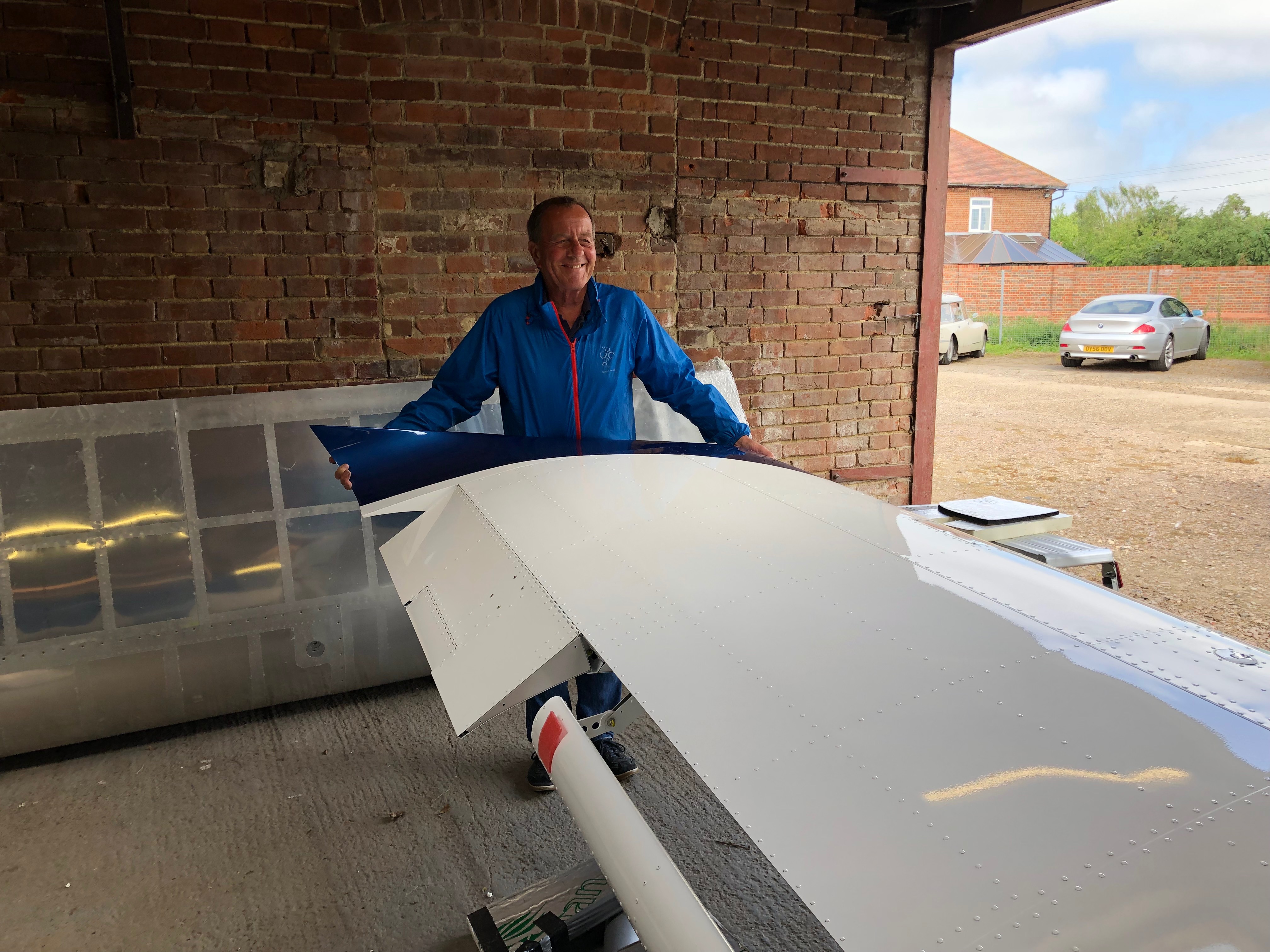
As mentioned before I decided to use superseal connectors as they are failproof and waterproof. I’d already completed quite a few of the connections but was distracted by another job. Whenever I’m distracted I always document what still needs to be done in my project plan.With all the connectors added the next job is to add an Amphenol to the end of the coax cable. It’s quite a complicated connector so I needed to test i on a cut off first. Once cut and trimmed the connector is soldered on to ensure a good connection.The finished connector, fairly straightforward but just needed to be thought about before committing,Now time to fit the wings so I can set all the ailerons, check the pitot, trim, flap, strobe and landing light circuits are working as wired. Ian and Peter Sharpe have offered to help and as usual Ian wears his designer gloves for the wing lift process. He looks quite fetching 🙂 Peter Sharpe at the ‘sharp’ end adding invaluable assistance. Once the wings are attached the main bolts need to be tapped home with a small nylon mallet before the nuts are added.With the wings added she’s a tight fit in the hanger with just 6″ between the front door and rear wall. If I had fitted the prop she wouldn’t fit!Now all the wiring has been completed and checked I can start to tidy th wiring. Ovrall I’m quite pleased with the results. Circuit Breakers……Bus Bars……Equipment trays and connectors…… and switches. All look a lot tidier now.She’s coming along nicely now and it won’t be long before I can start engine tests…
Finishing off the trim wiring, fitting and wiring the control stick grips,
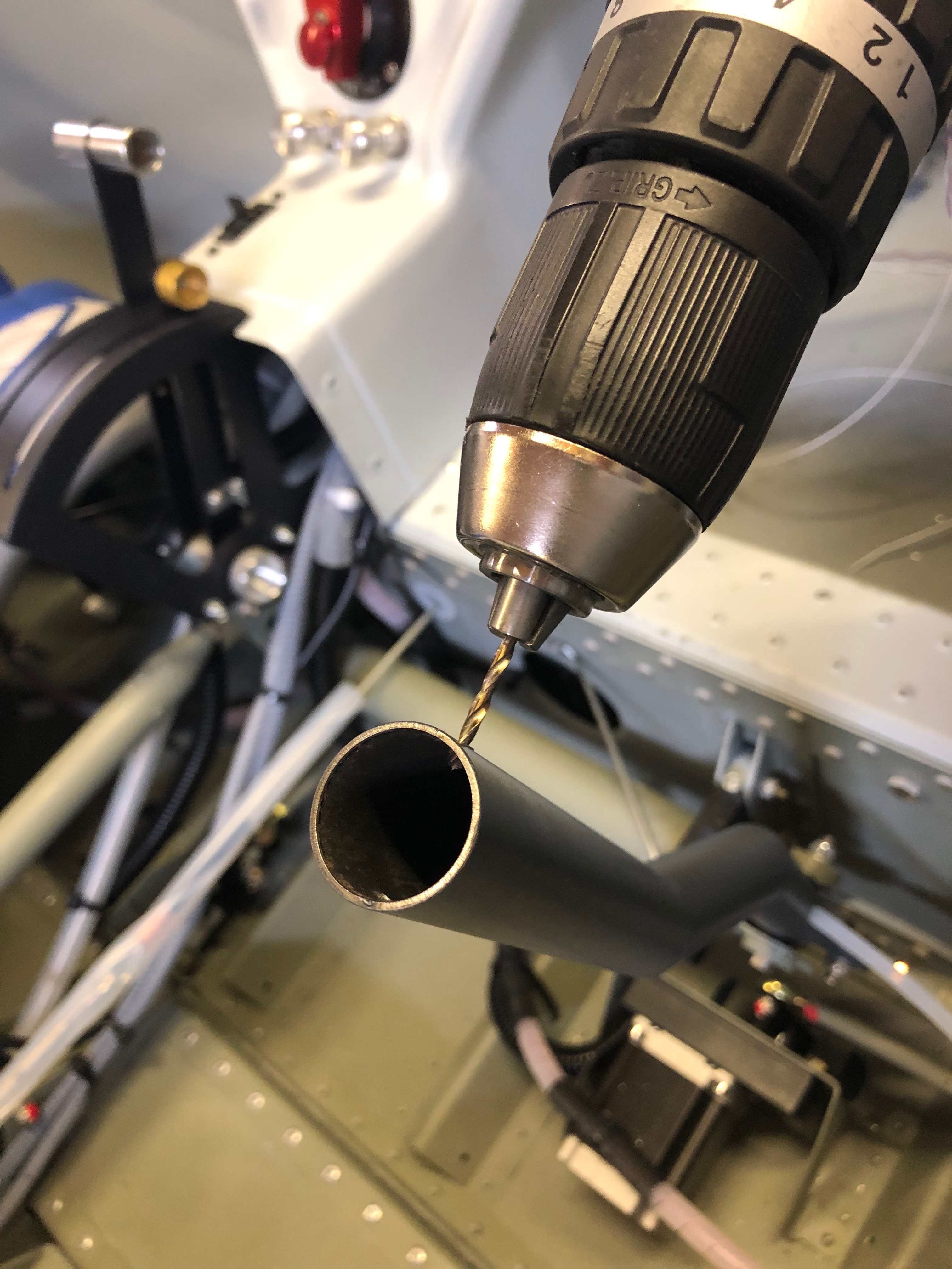
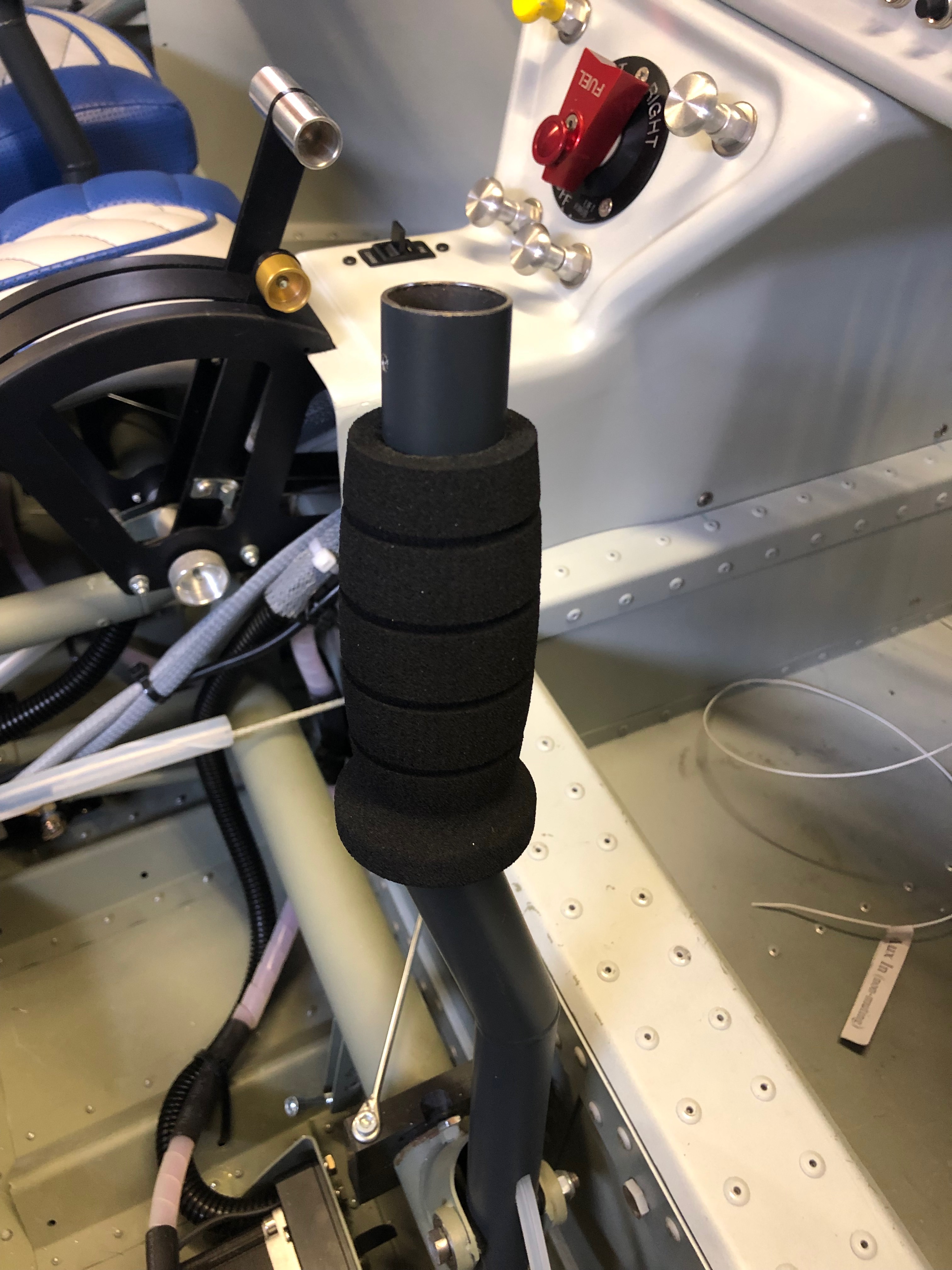
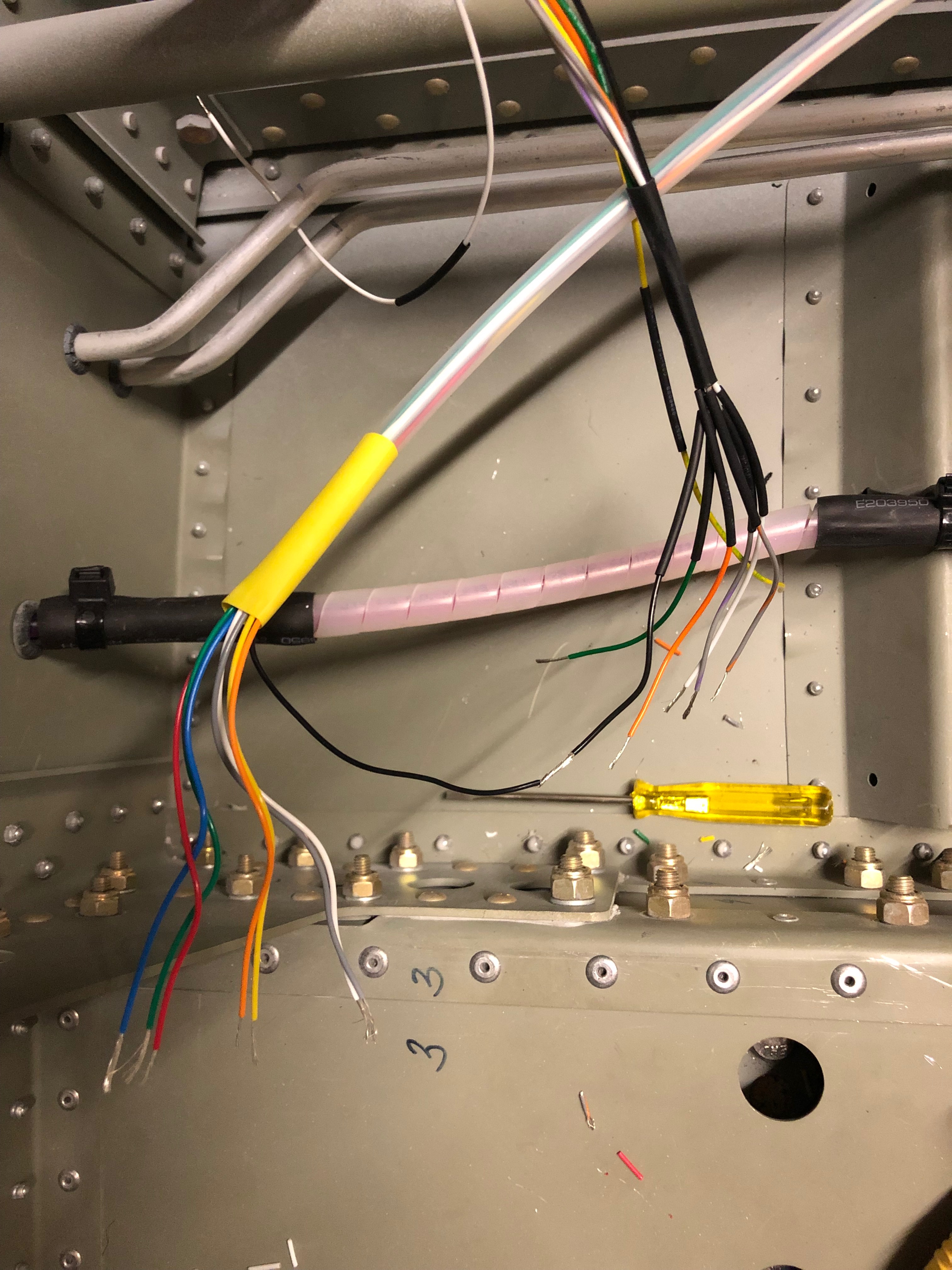
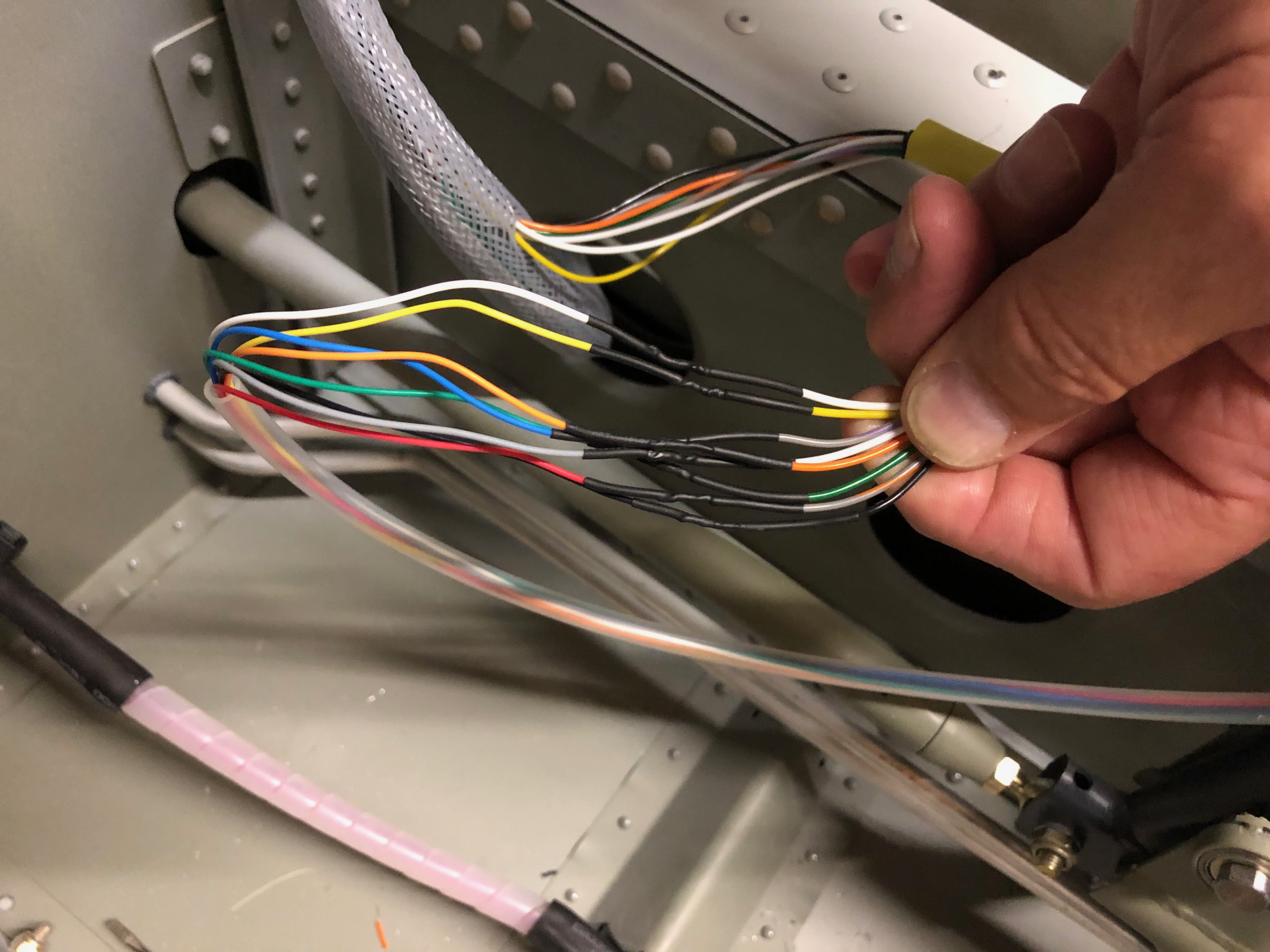
After a lot of head scratching the trim system is finally wired just need to wire up the control sticks to finish off a very long day.The Bristell trim kit supplies G405 stick grips but I wanted to add a autopilot disconnect switch on the stick so went for the G407 instead.It’s suggested that that the stick grips are riveted to the stick but I think it better to drill and tap so you can remove them easily at a later stage if required.I’ve used M3 button head screws to secure the top.The stick grips are slid onto the control stick but are a very tight fit so require a bit of lubrication to ease the process.With the stick grips fitted I just need to wiring them up. Pleased with the result so far..Another batch of wires. This time eight the need to be soldered together. The only difficult bit it mapping the differing colours between the control stick and the wires that are connected to the trim controller.Soldering complete just need to record the colour mapping for my documentation.
Following the build of my Bristell NG5 Kit No. 382 Registration G-MLSY