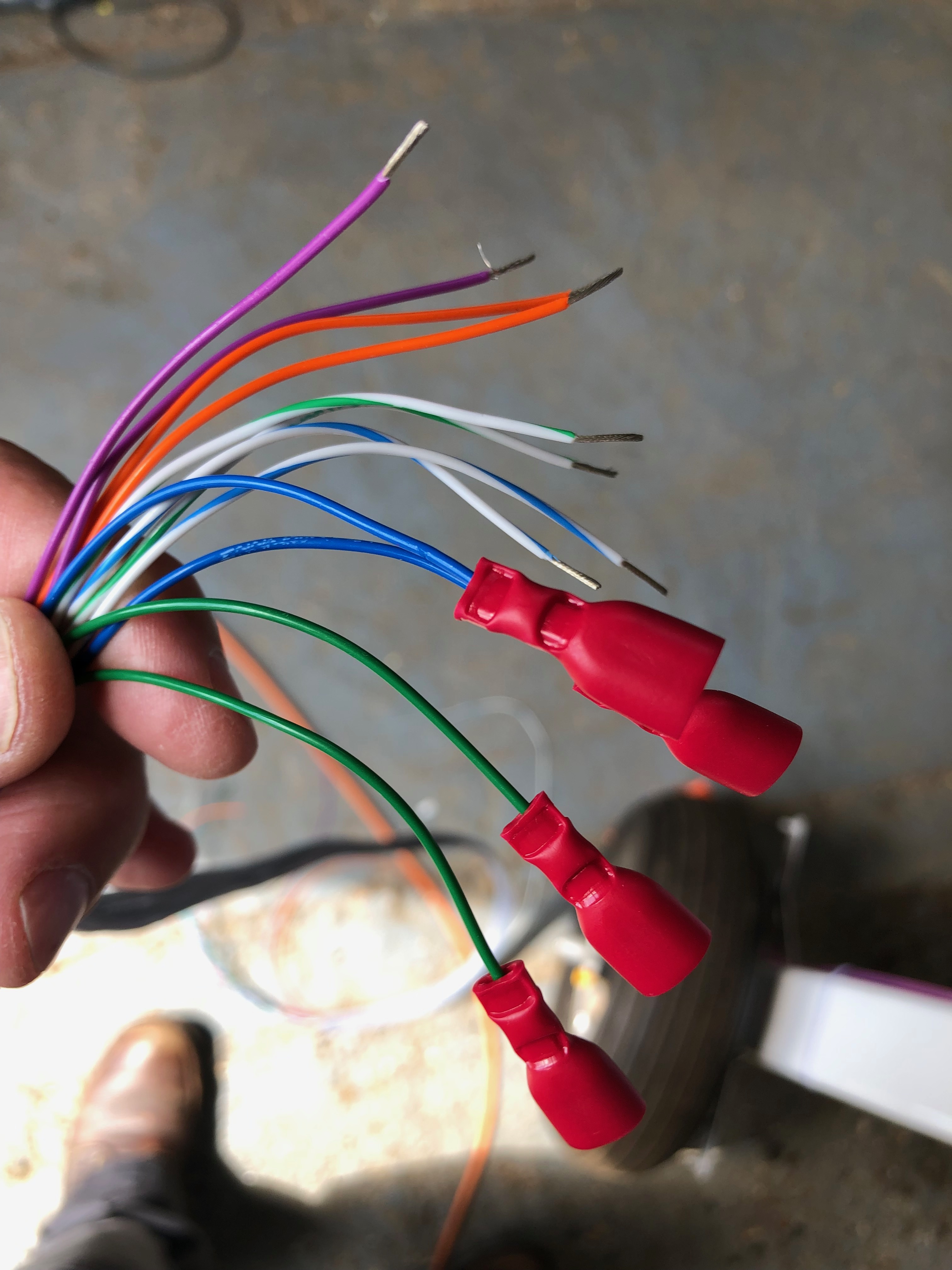
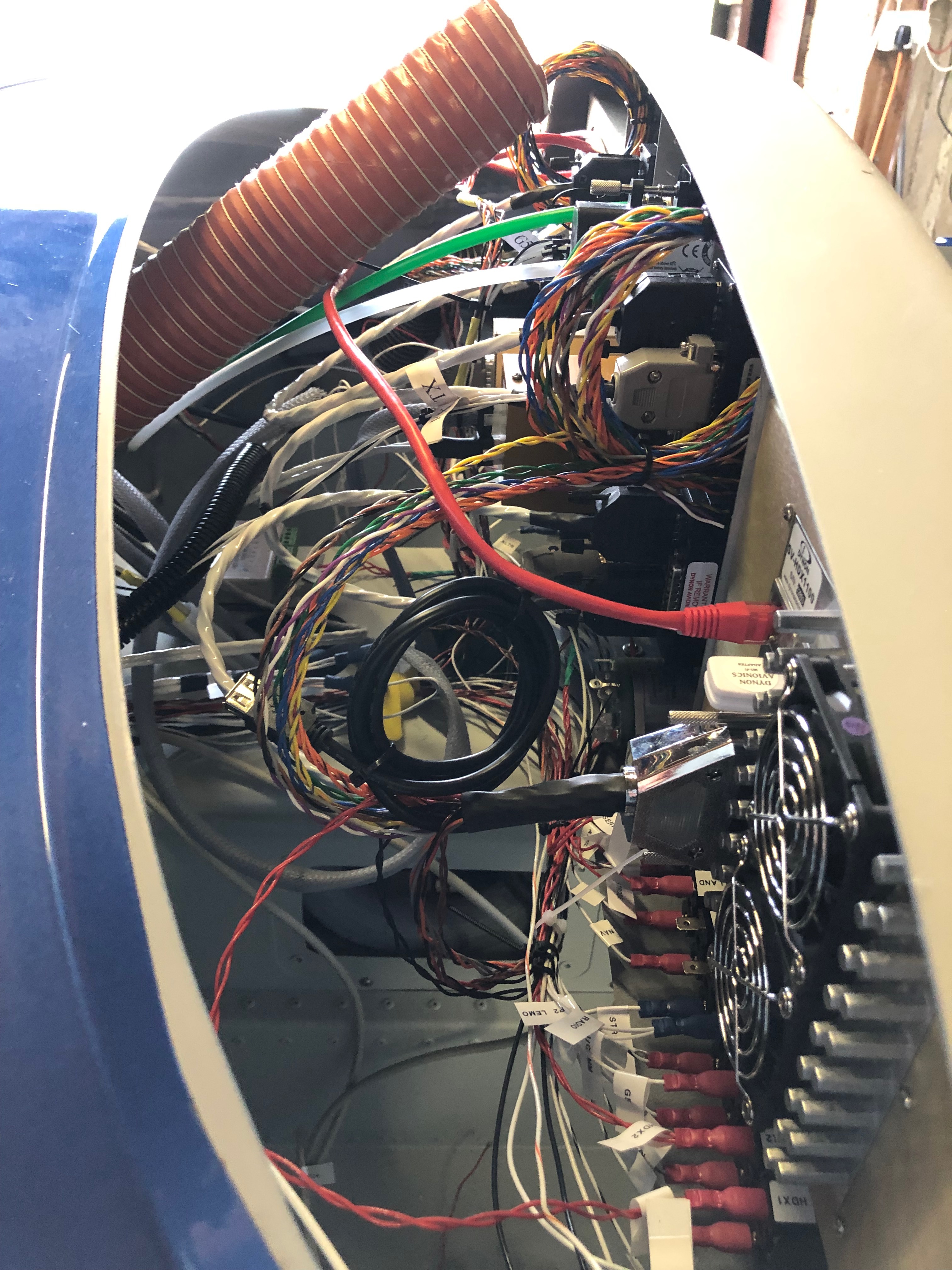
it’s time to fit the wings so I need to add the connectors to the trim, landing lights and heated pitot looms that I have already run in. I’ve also run in the radio coax cable so need to terminate that and carry out a final tidying up of the wiring.
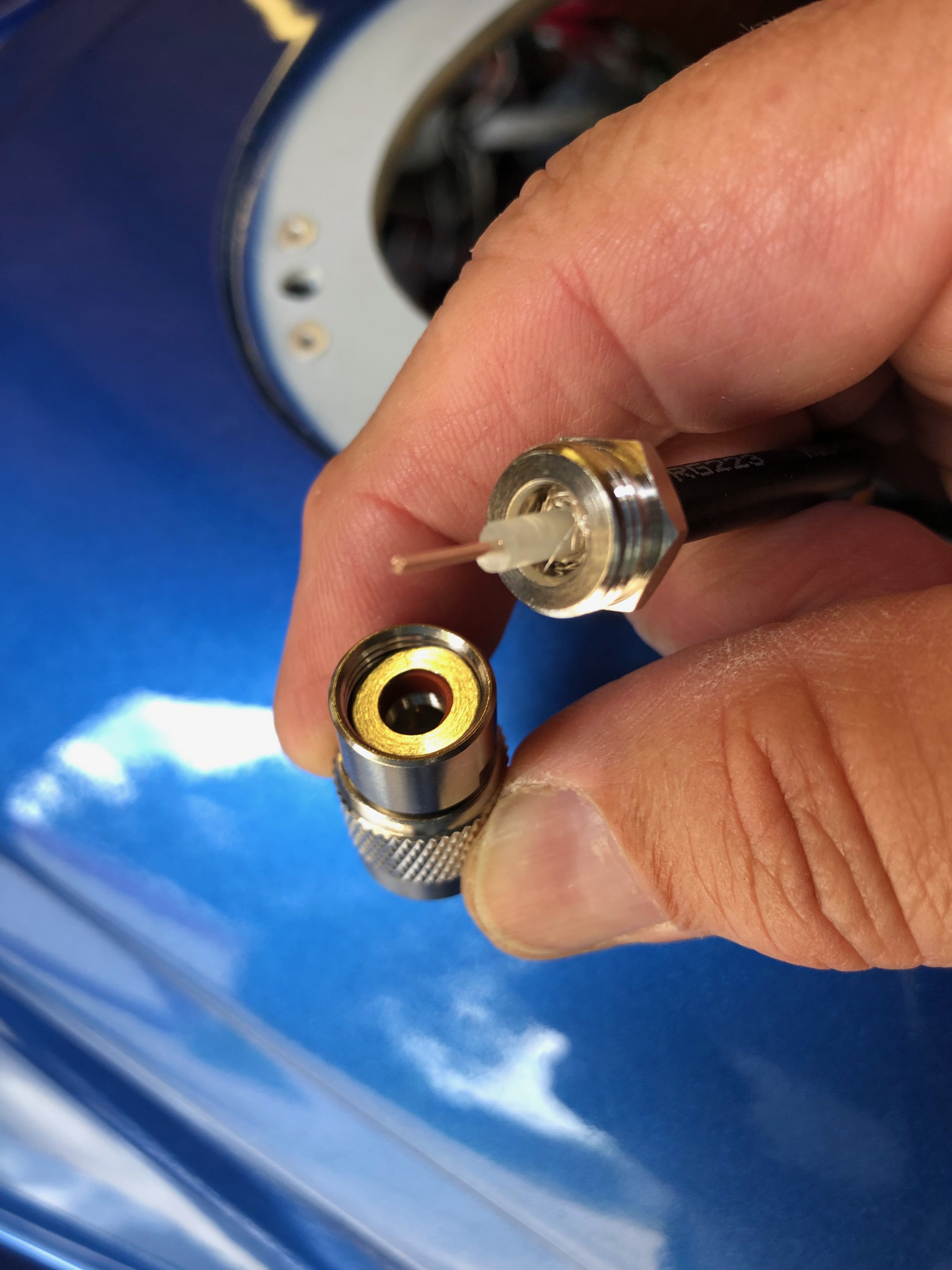
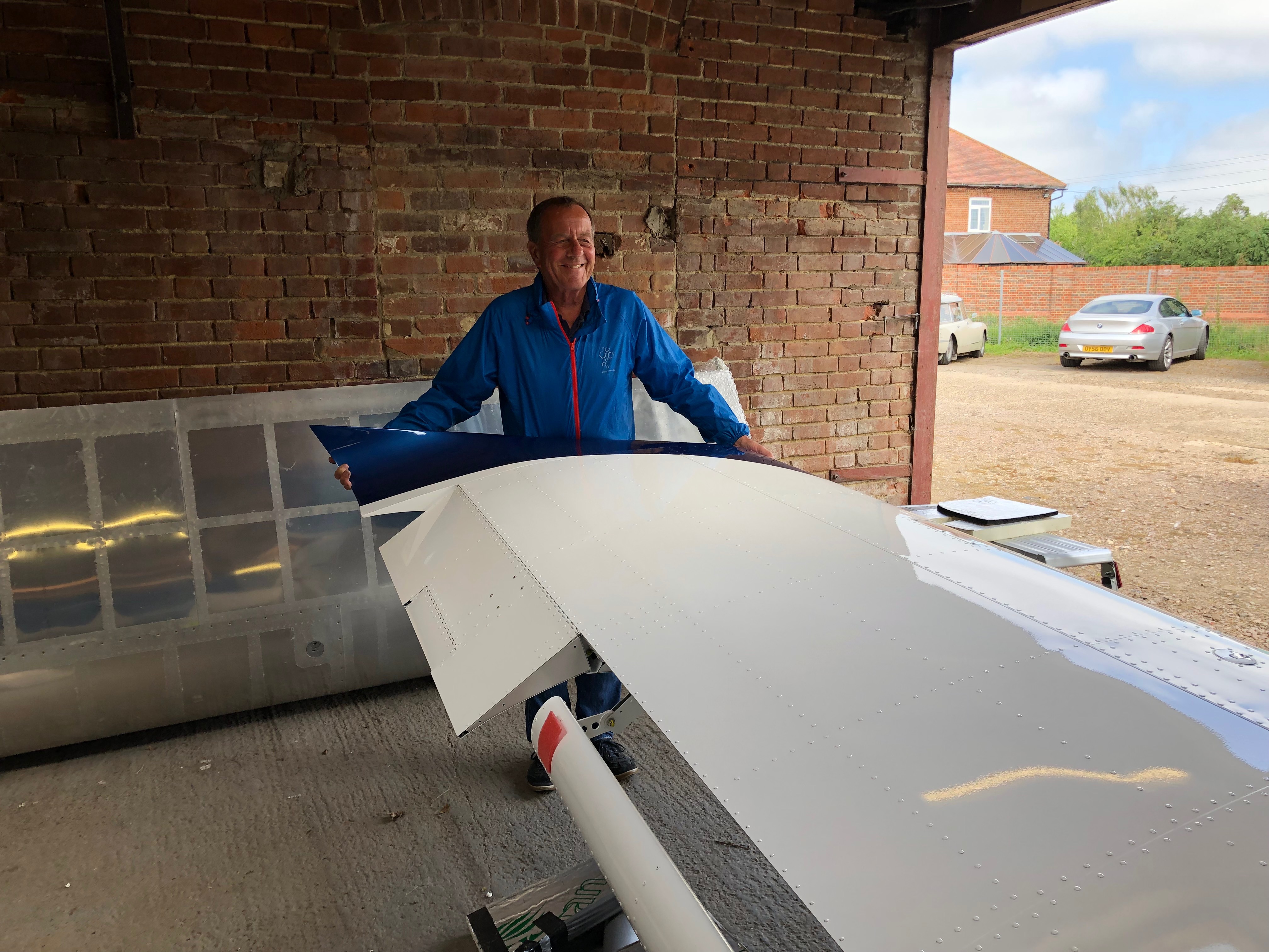
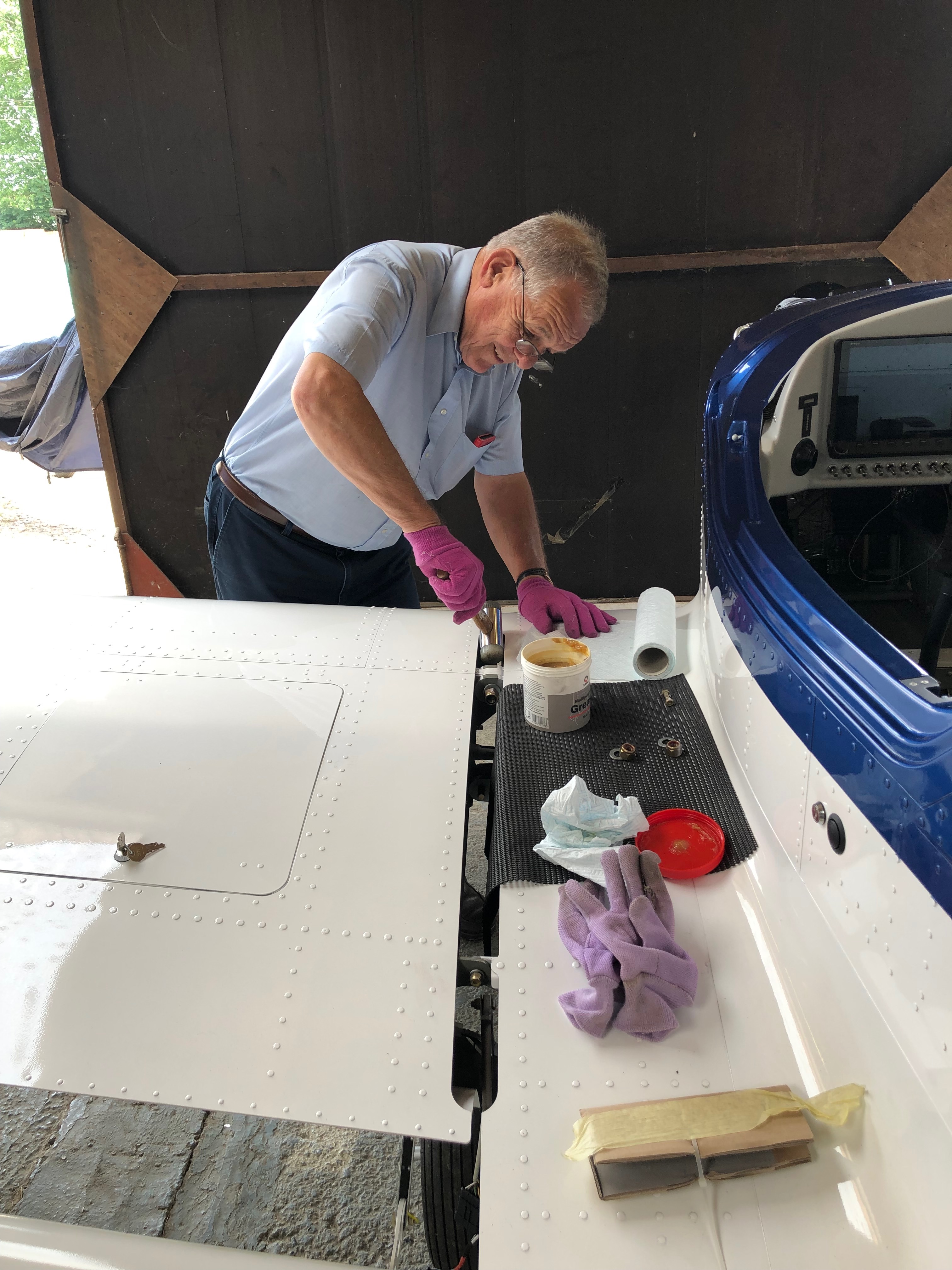
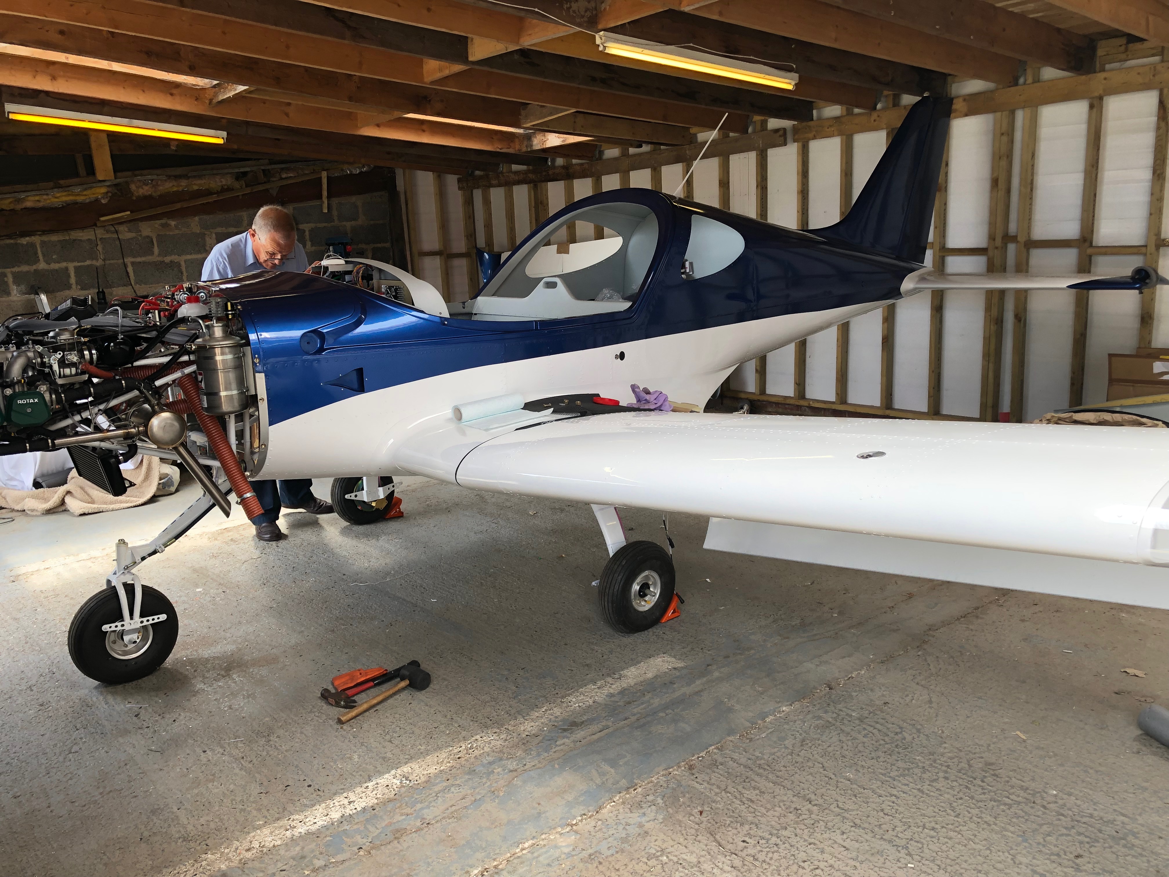
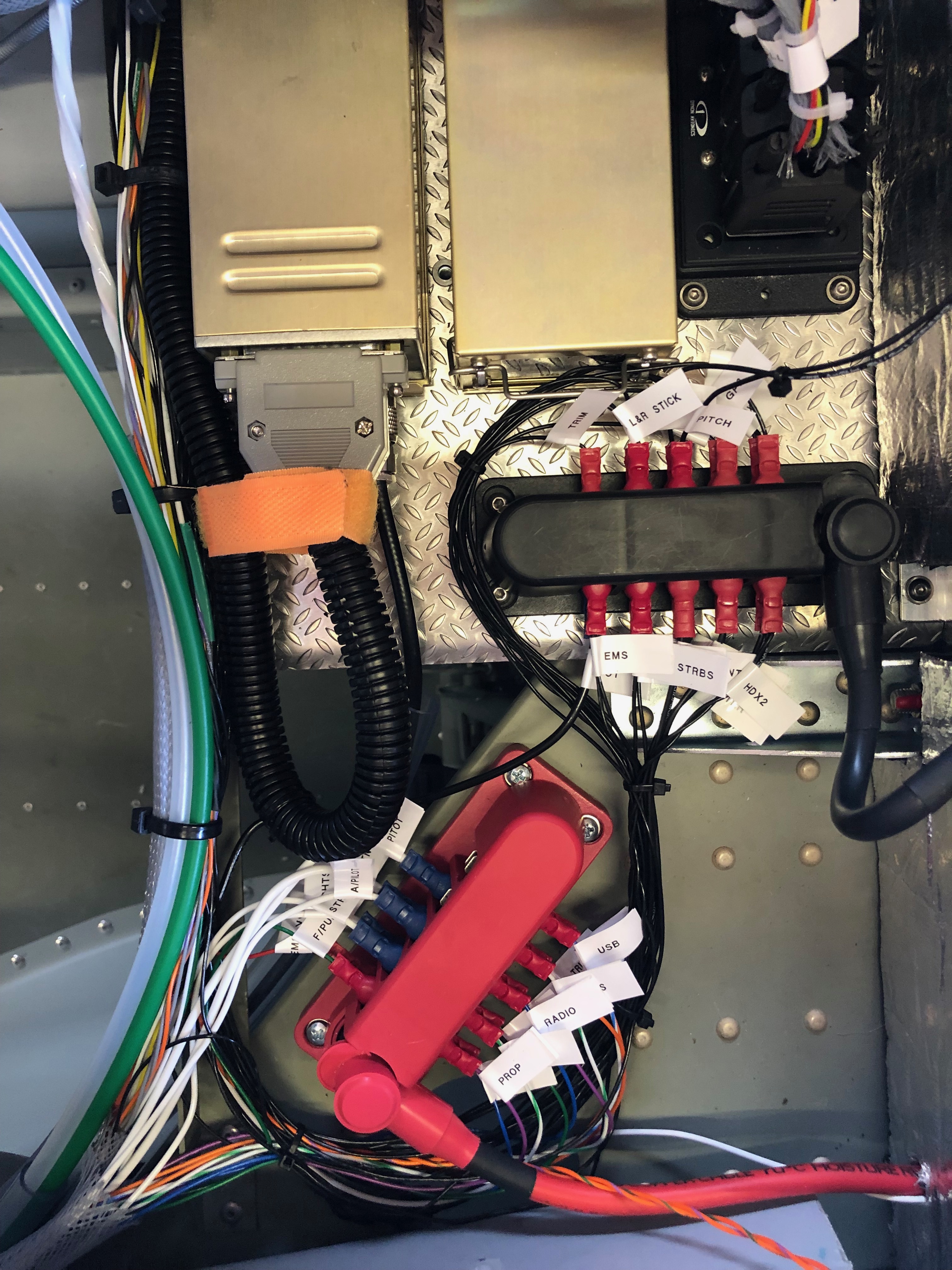
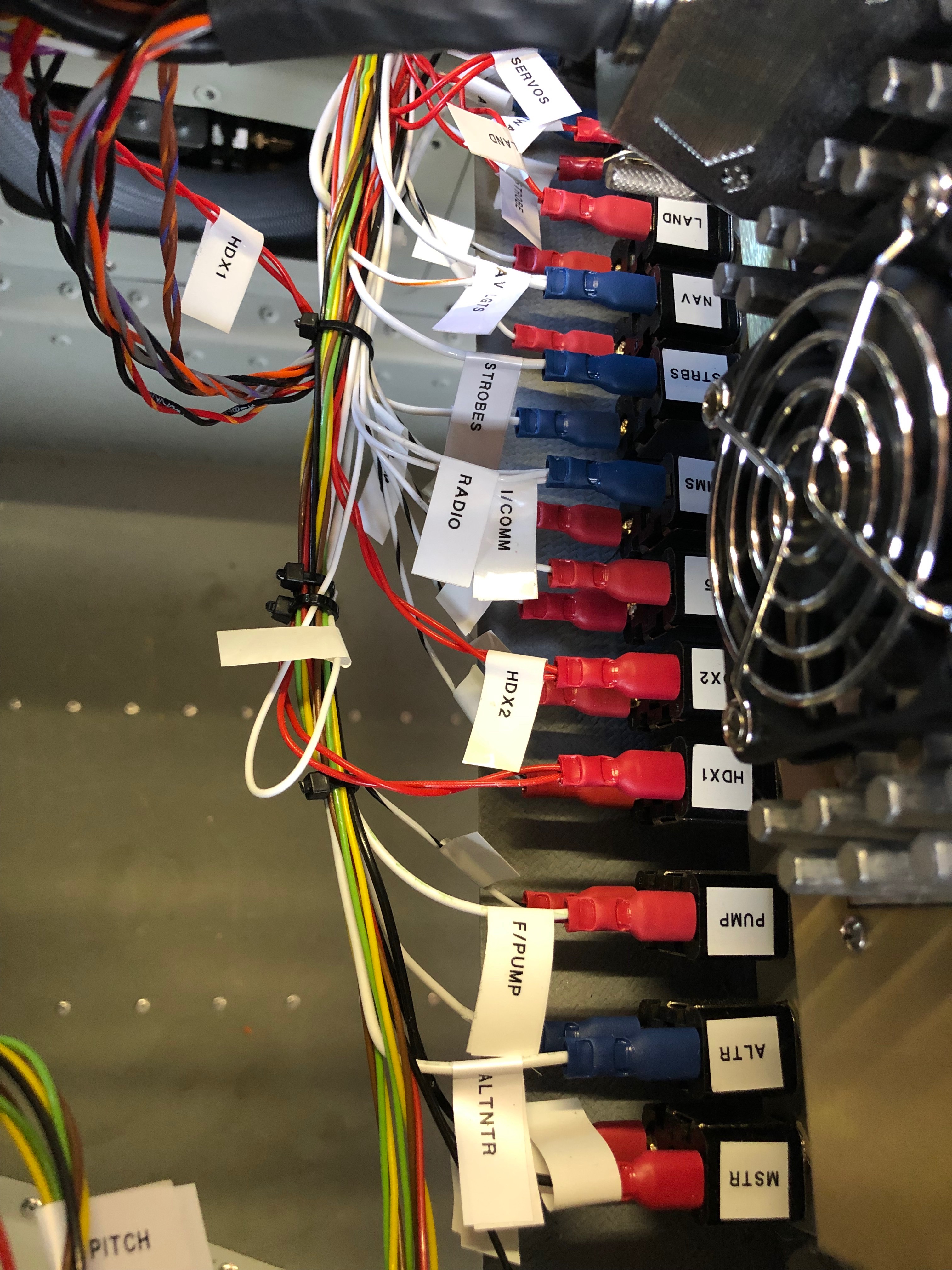
As mentioned before I decided to use superseal connectors as they are failproof and waterproof. I’d already completed quite a few of the connections but was distracted by another job. Whenever I’m distracted I always document what still needs to be done in my project plan.With all the connectors added the next job is to add an Amphenol to the end of the coax cable. It’s quite a complicated connector so I needed to test i on a cut off first. Once cut and trimmed the connector is soldered on to ensure a good connection.The finished connector, fairly straightforward but just needed to be thought about before committing,Now time to fit the wings so I can set all the ailerons, check the pitot, trim, flap, strobe and landing light circuits are working as wired. Ian and Peter Sharpe have offered to help and as usual Ian wears his designer gloves for the wing lift process. He looks quite fetching 🙂 Peter Sharpe at the ‘sharp’ end adding invaluable assistance. Once the wings are attached the main bolts need to be tapped home with a small nylon mallet before the nuts are added.With the wings added she’s a tight fit in the hanger with just 6″ between the front door and rear wall. If I had fitted the prop she wouldn’t fit!Now all the wiring has been completed and checked I can start to tidy th wiring. Ovrall I’m quite pleased with the results. Circuit Breakers……Bus Bars……Equipment trays and connectors…… and switches. All look a lot tidier now.She’s coming along nicely now and it won’t be long before I can start engine tests…
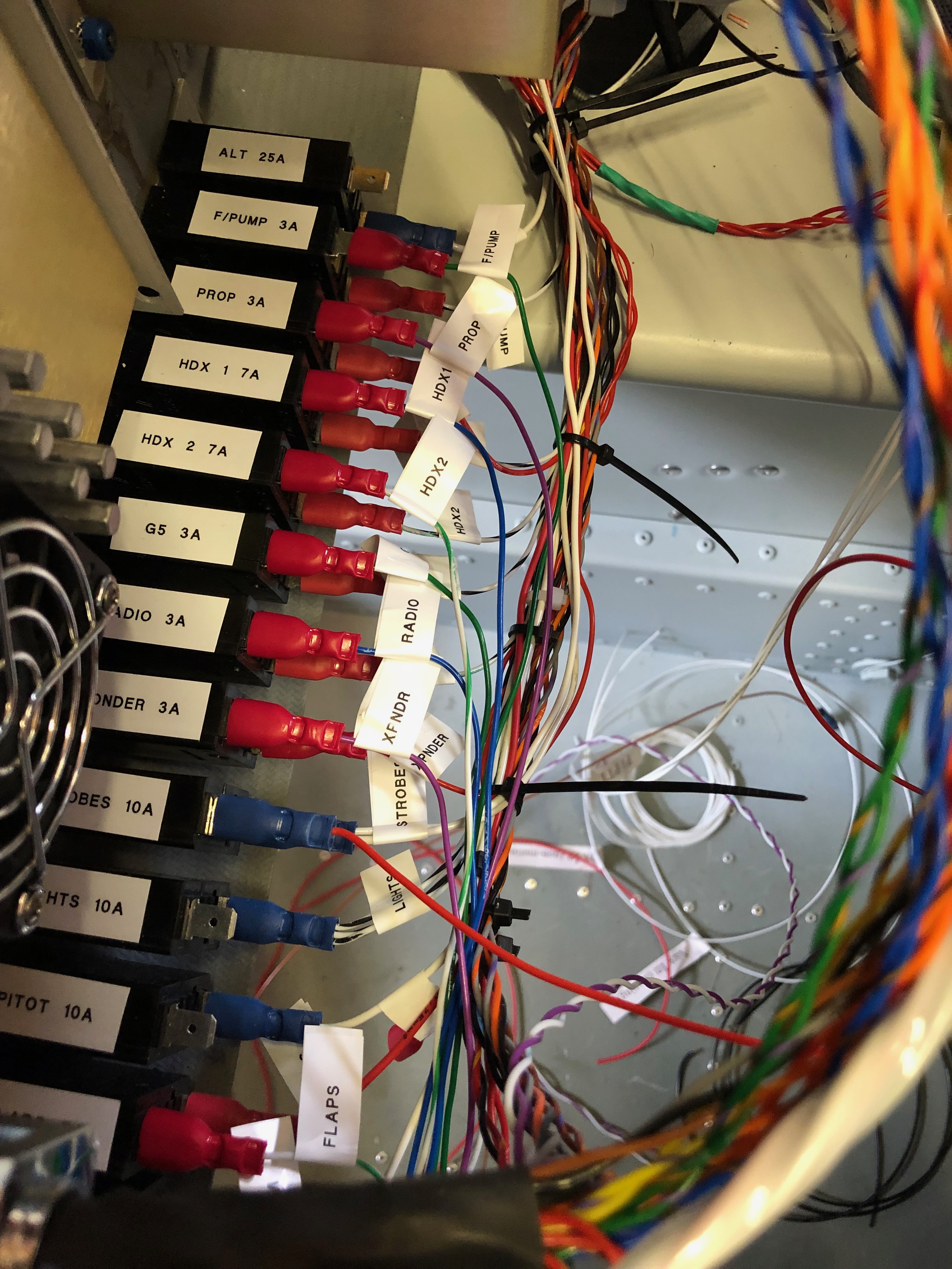
A lot to do today, as every day! When the delivery arrived I found that some of what I had ordered was out of stock. It’s not a big problem as there are lots of other jobs to do. So I’ll wire up the power side of the system and label, install and test the radio and transponder coax cable.
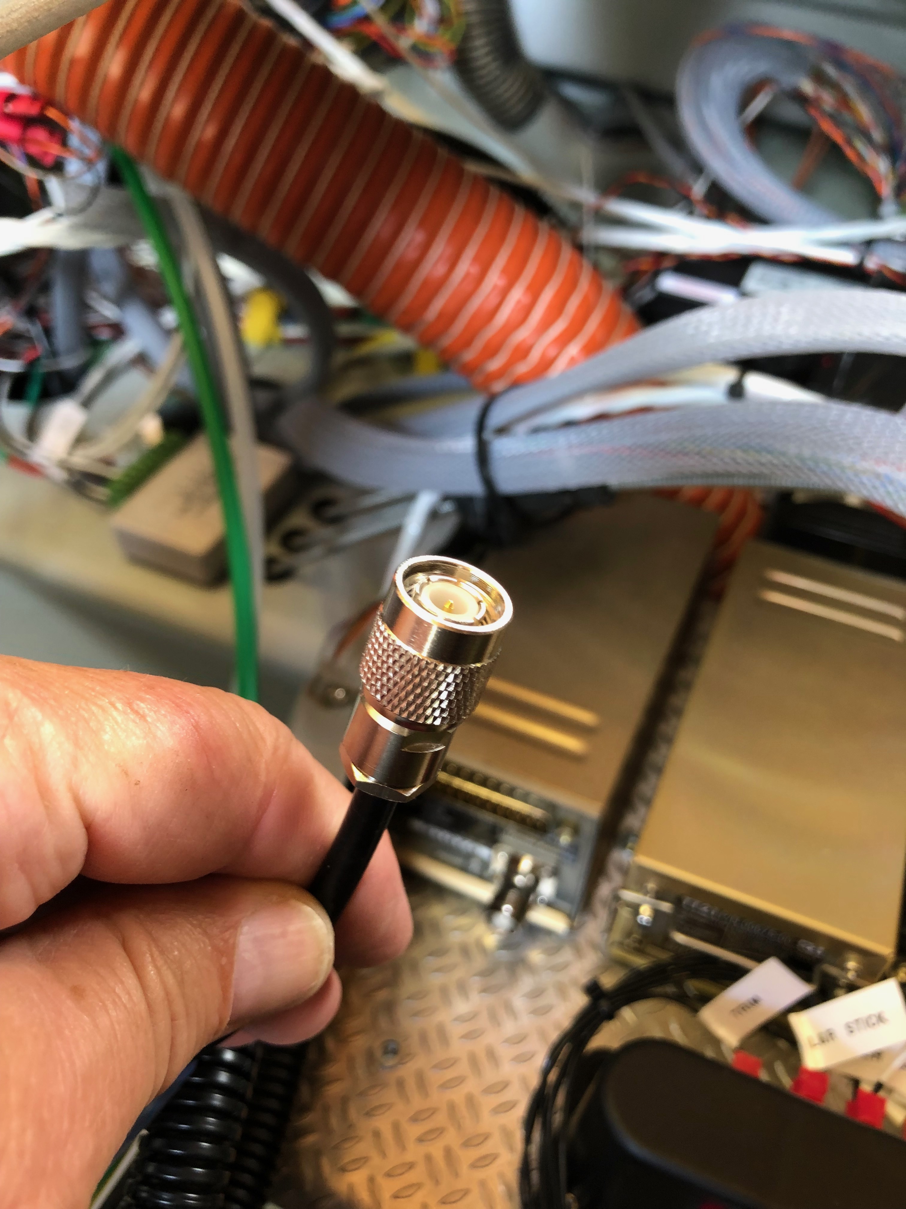
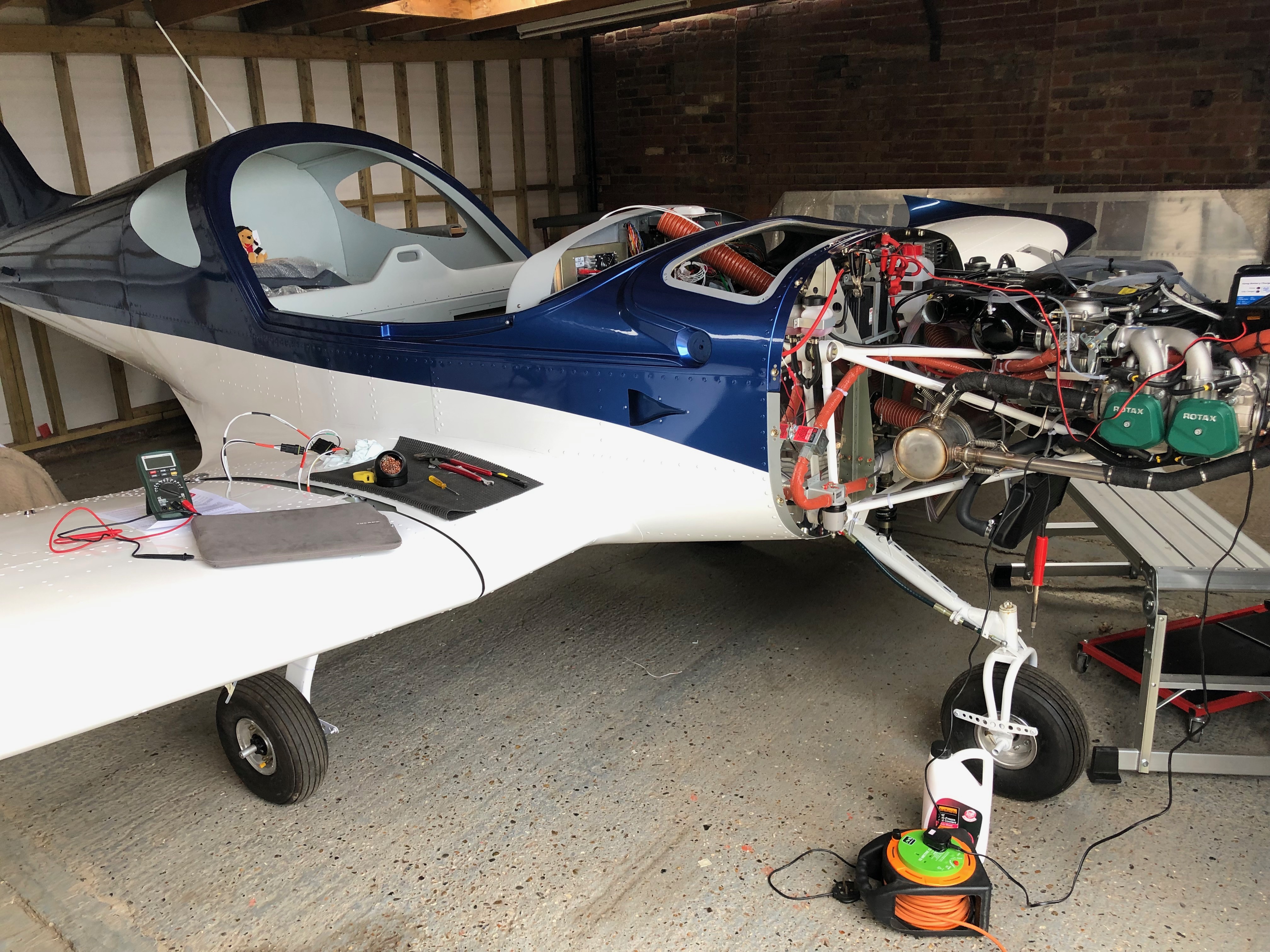
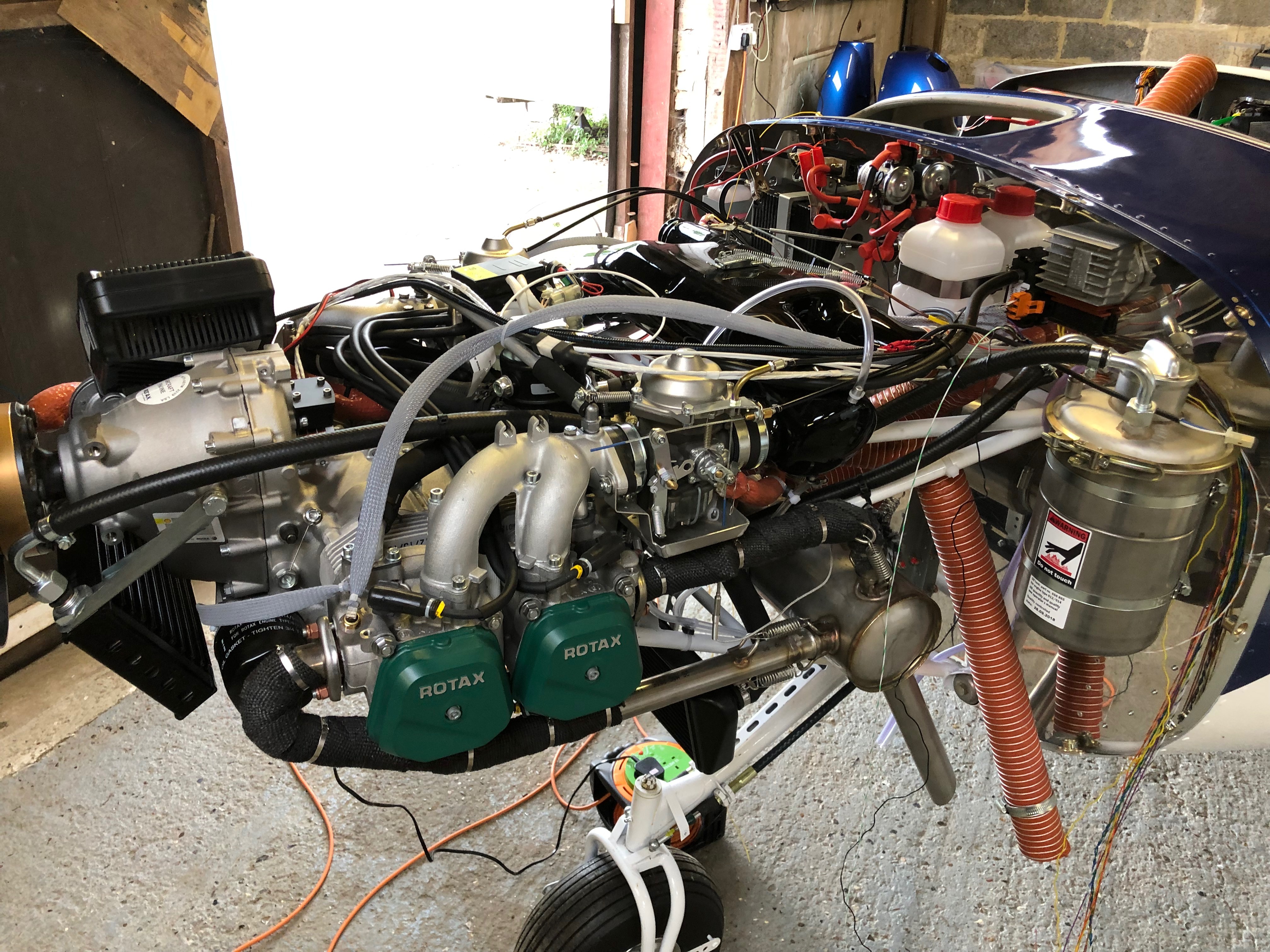
Time to wire up the power side of the electrical system. I’m reusing the wire that I have leftover from the other circuit wires that were trimmed back. There’s plenty to do the job although not a unified colour as long as they are labelled it will be ok.My new friend. A Dymo Label Manager 200 that I bought some years ago. It’s been invaluable and luckily I managed to get some label cartridges.The +ve bus with 11 of the circuits completed.The circuit breakers connected, some tidying will be required but it’s mostly complete.The complete panel powered up for the first time. The system shows a 7 amp power drain which is roughly what I had calculated.My DPD delivery was a day late but got delivered at 10am so I could get on with the wiring of the Transponder and Radio with the coax.The radio coax cable runs through conduit in the fuselage and is terminated with a TNC connector that I’ll do tomorrow.With all the cables protected with sleeving or conduit and secured in place I can fit the interior trim.The rear of the cabin. I’ve checked the radio/headset loom and it works fine so I need to mount the LEMO headset connectors and then I can fix the interior panels.Right side of engine. All the sensors are connected except the Tachometer, soft start module, magneto wires.Left side of engine. Looks a bit busy but with a bit od tidying it will look a bit neater. Quite pleased with the progress so far.
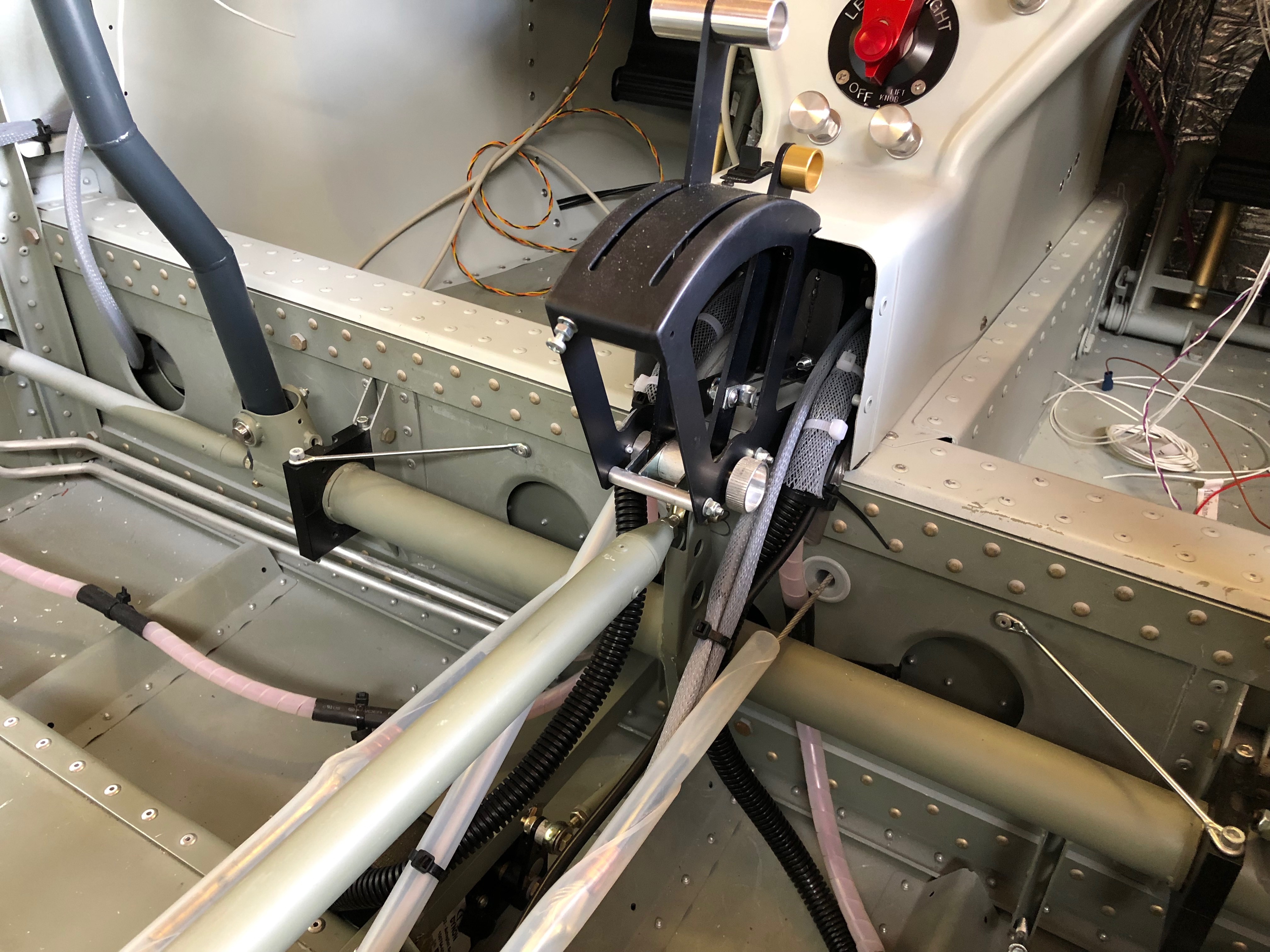
Dave came down to spend a day with me to see how the build is going so far and help me with fitting the prop hub and transponder aerial.
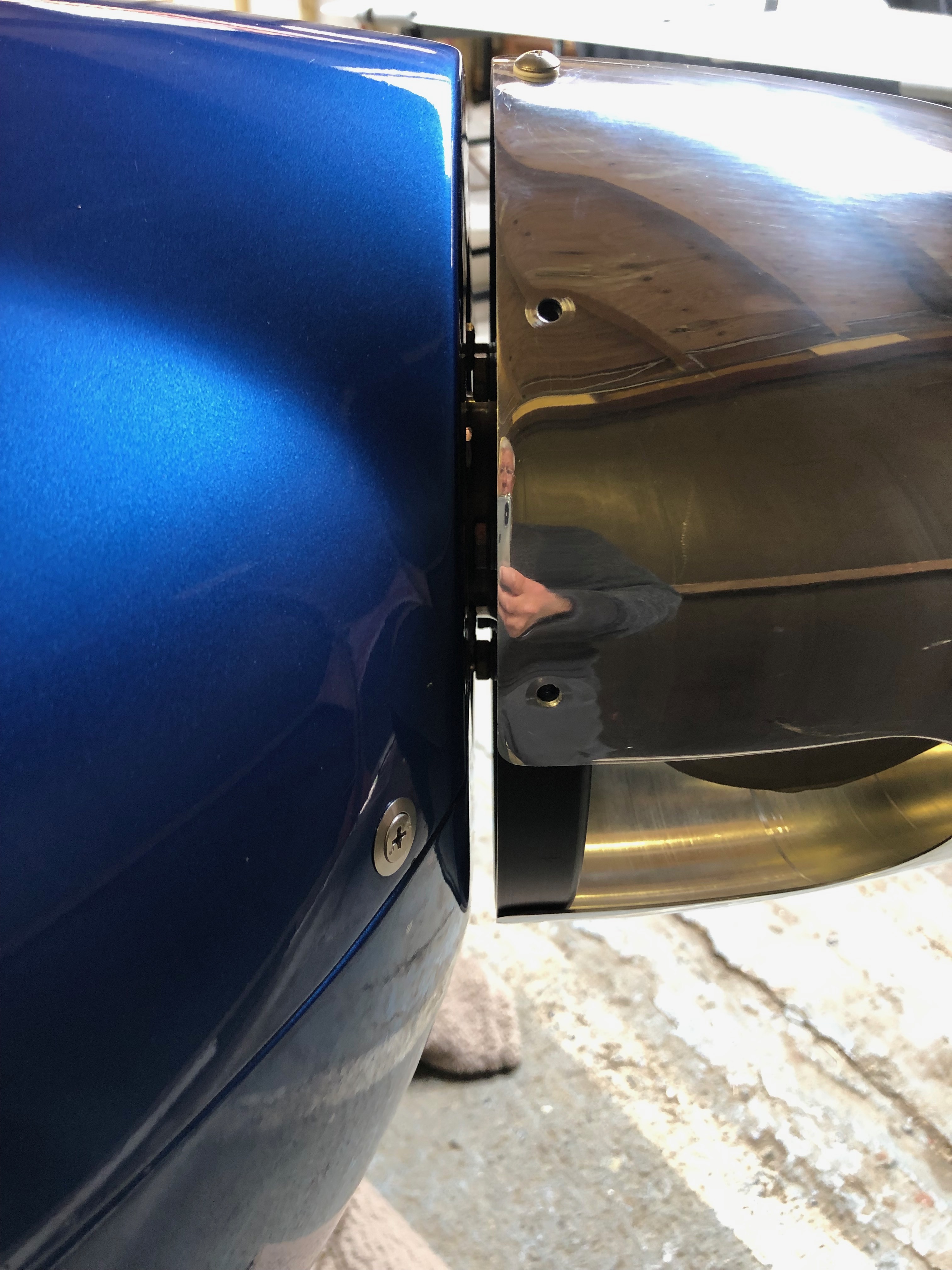
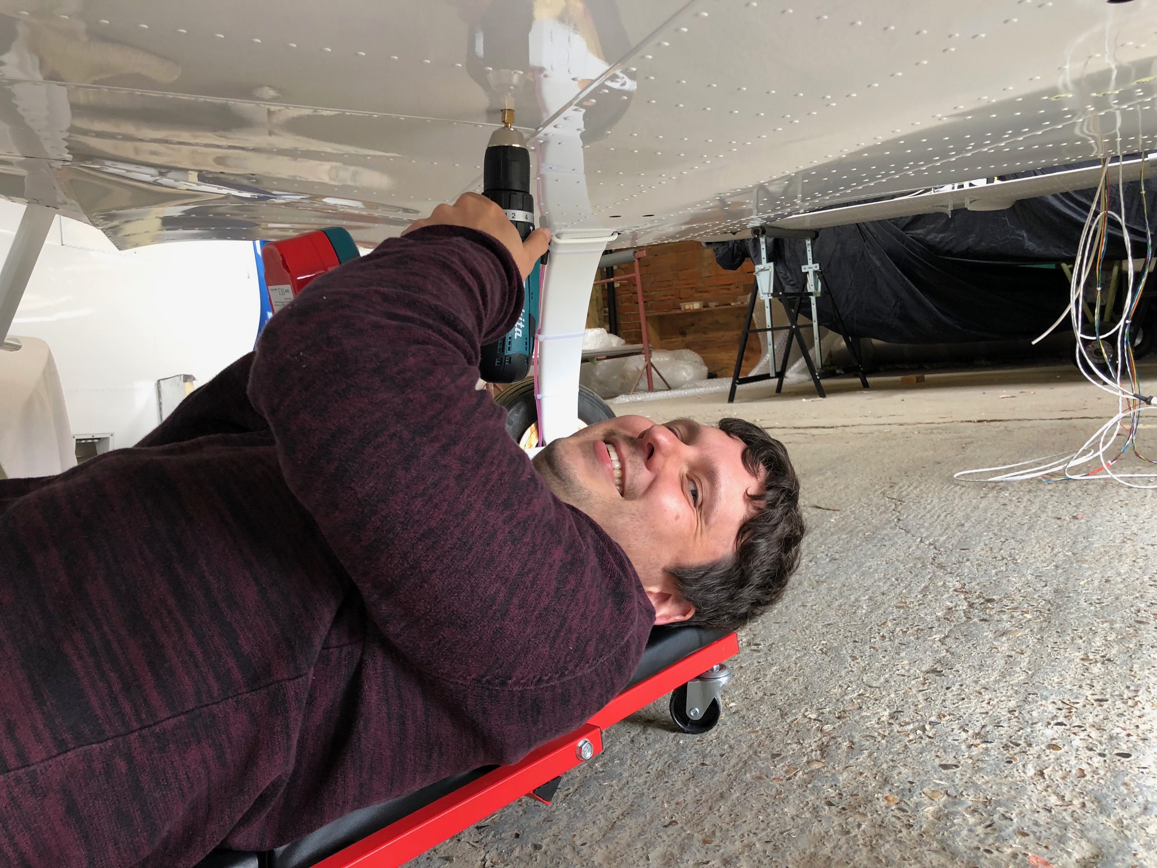
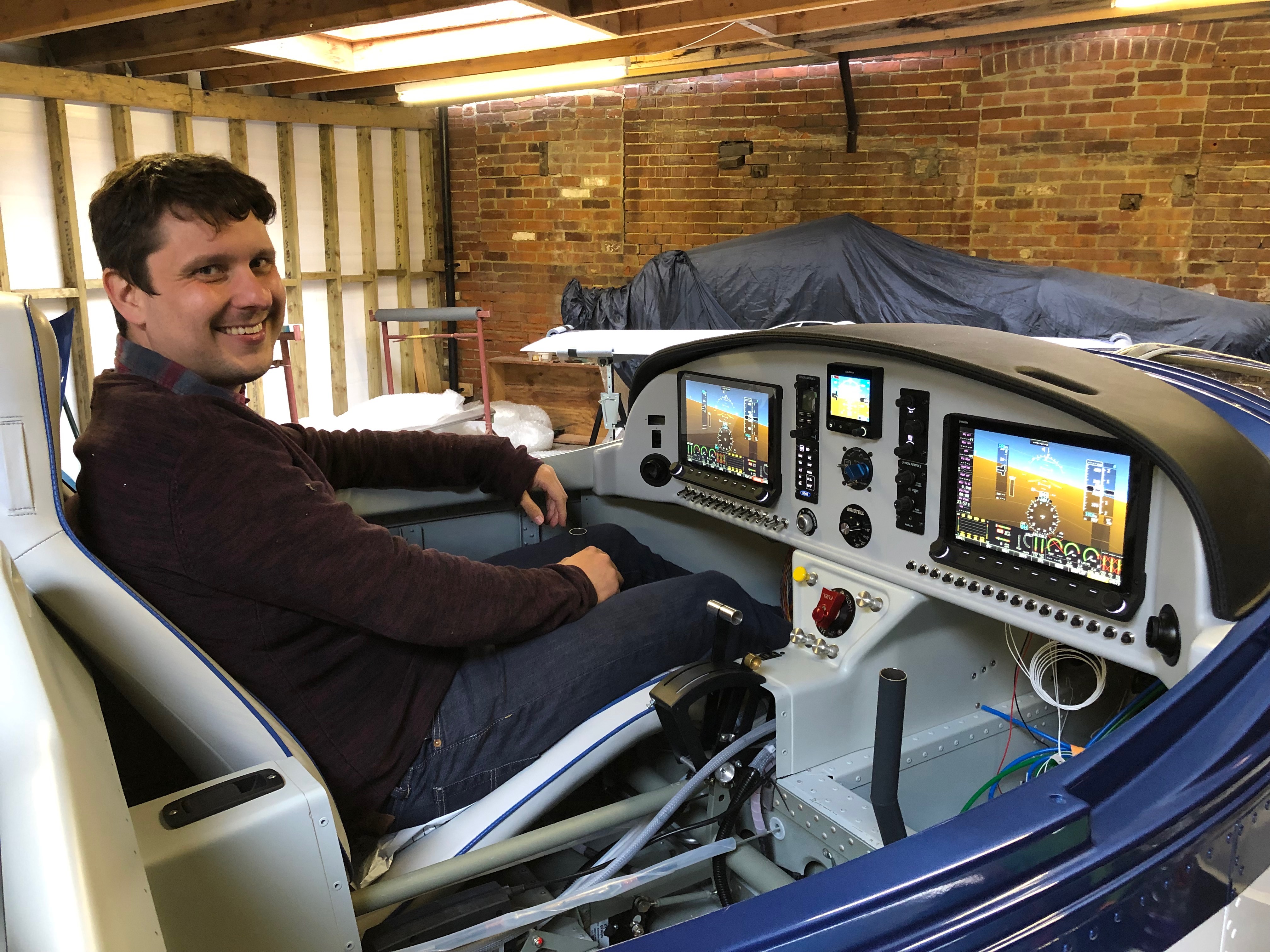
Forgot to attach the panel air vent ducting before I installed the panel. It’s a lot more fiddly i can tell you!Now I’ve received the drive lugs I ordered from CFS Aero I can attach the prop extension to the drive plate. The bolts to attach the extension to the drive plate are 8mm and the bolts to attache the prop back plate are AN5. So metric and imperial in the same installation – how ridiculous! The drive lugs are press fit and have a slight taper so the bolts are used to draw the lugs into the drive plate.The bolts have been lightly tightened before torquing up to 24NM.The mini slip ring control wires are adjusted so they hang just out the of the front of the prop extension.Heat shrink tubing is added to each wire and the hub offered up to allow the control wires to be connected.A heat gun is used to heat the heat shrink and the wires are pushed into the hollow shaft.Some Duralac is added to the lugs that enter the hub to ease disassembly and the bolts tightened.Time to check that I’ve got the measurements right for the prop extension so the engine cowlings are fixed in place.A good fit with an acceptable gap, so shouldn’t rub in service. I’ll fit the blades closer to finishing the plane to save them getting damaged.Next up is to install the transponder aerial. I’ve decided to mount it centrally between the main wheels. Still have to make up the coax for the radio and transponder but going to Air Expo on Thursday so will look to pick it up there.Dave checking out the pilots seat before leaving for home.So most of the main work has been completed so it’s time to start on the wiring. Not sure how long it’s going to take but need to make a tidy job of it and make sure that it’s easy to trace and maintain in the future.
Not a lot of action today as I was looking at the avionics kit to see where it can all be mounted so just mounted the VHF aerial.
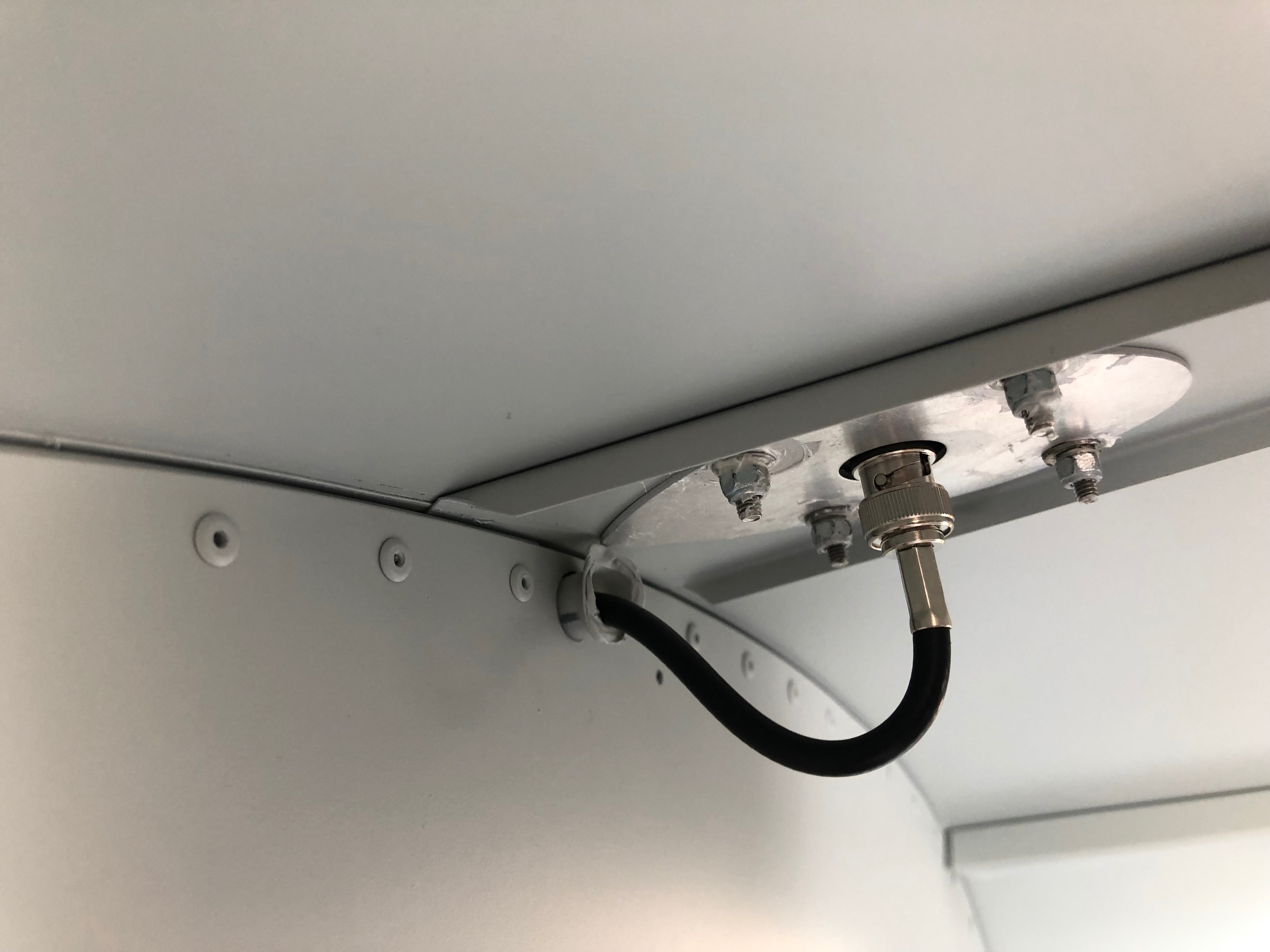
The top surface just behind the canopy is already drilled for VHF whip aerial.
The aerial to be fitted has a BNC coaxial connection on it’s base that can be accessed from within the rear cabin.
The screws that fix the aerial onto the fuselage have cup shaped anti shake washers to hold them.
To ensure that water doesn’t make its way past the screws and down the threads I’ve used some silicone to seal them before tightening them.
The finished installation after running some silicone sealer around the base of the aerial.
To get an idea of how the avionics connect together I laid it out and connected it up. I’d already charged the backup batteries up so they allowed me to power most of the system up. The ADAHRS, Servos, Radio and Transponder can’t be powered up as it needs wiring but it gives me a good idea of how it can be laid out in the Aircraft.
Following the build of my Bristell NG5 Kit No. 382 Registration G-MLSY