Since my first solo flight in G-MLSY on the 22nd November I’ve managed to log around 9 hours in 15 flights. The weather has been kind and quite dry. All of them have been used to familiarise myself with the aircraft and understand the flight characteristics and systems. It’s a delight to fly, reasonably fast and very responsive.
MLSY looking very sleek with her spats on.The Kent coast is lovely to fly round. Herne Bay pier
One of the things I needed to do was tune the autopilot. So where shall I go? I thought a little message to Karen would be very appropriate after all the support and encouragement she’s given me during the build so I programmed this up on SkyDemon and sent it to the SkyView.
Once I had taken off I engaged the autopilot and let it do the rest. I adjusted a few autopilot settings during the flight but it worked faultlessly. It’s a very impressive set up.
This flight can be seen on FlightRadar24 by searching for G-MLSY on 3rd December.Flying the route round the heart.
A lot to do today, as every day! When the delivery arrived I found that some of what I had ordered was out of stock. It’s not a big problem as there are lots of other jobs to do. So I’ll wire up the power side of the system and label, install and test the radio and transponder coax cable.
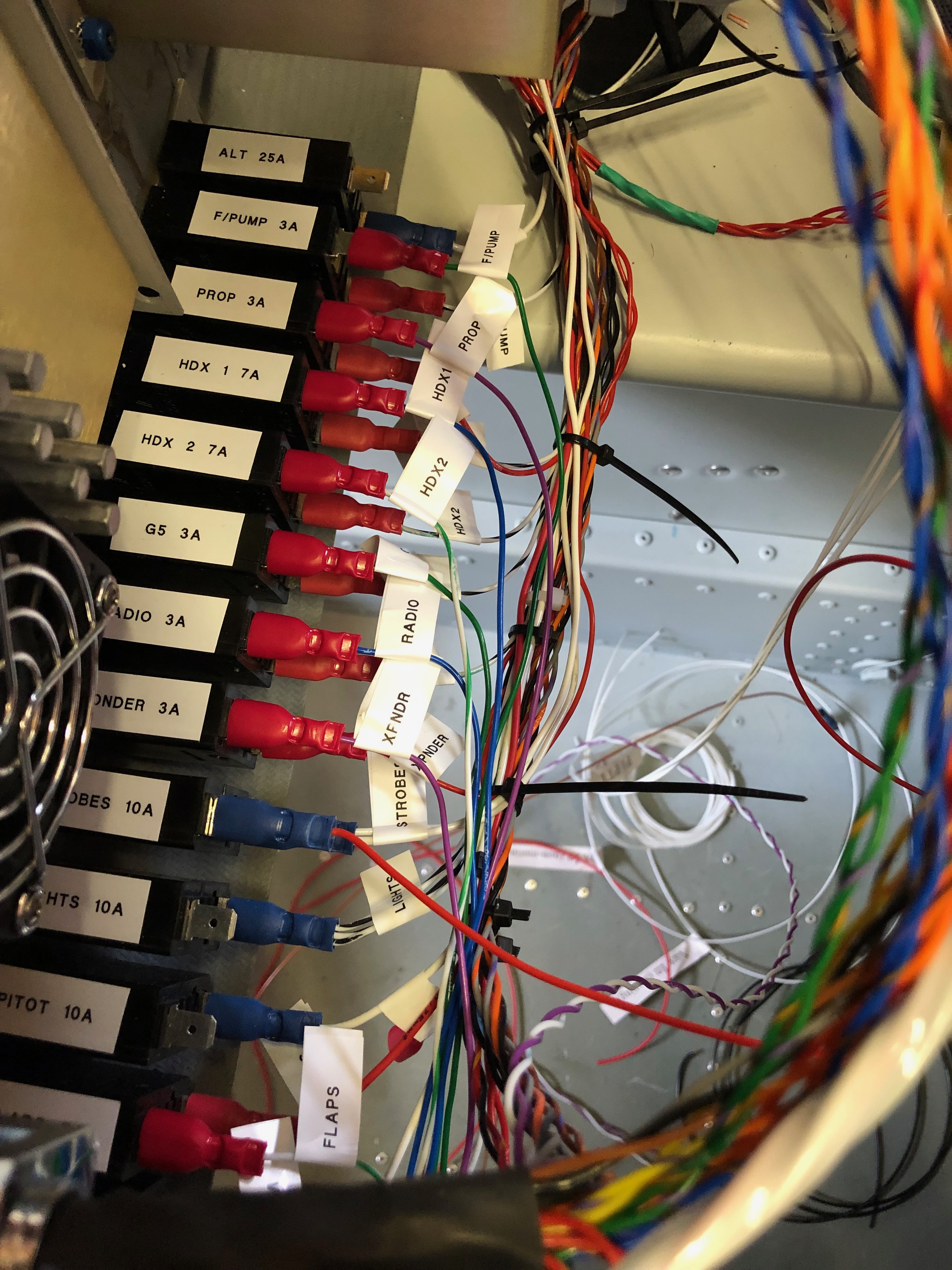
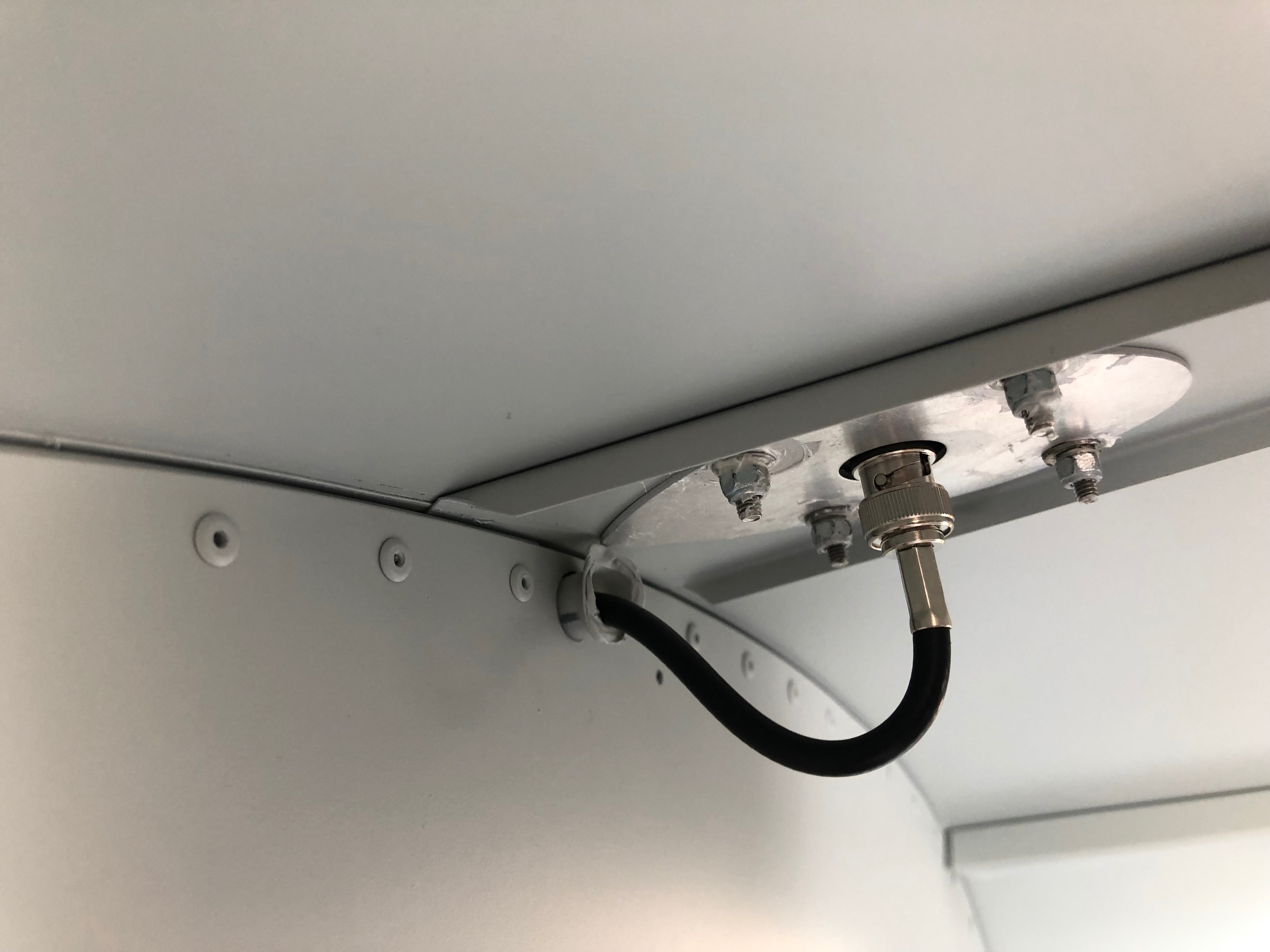
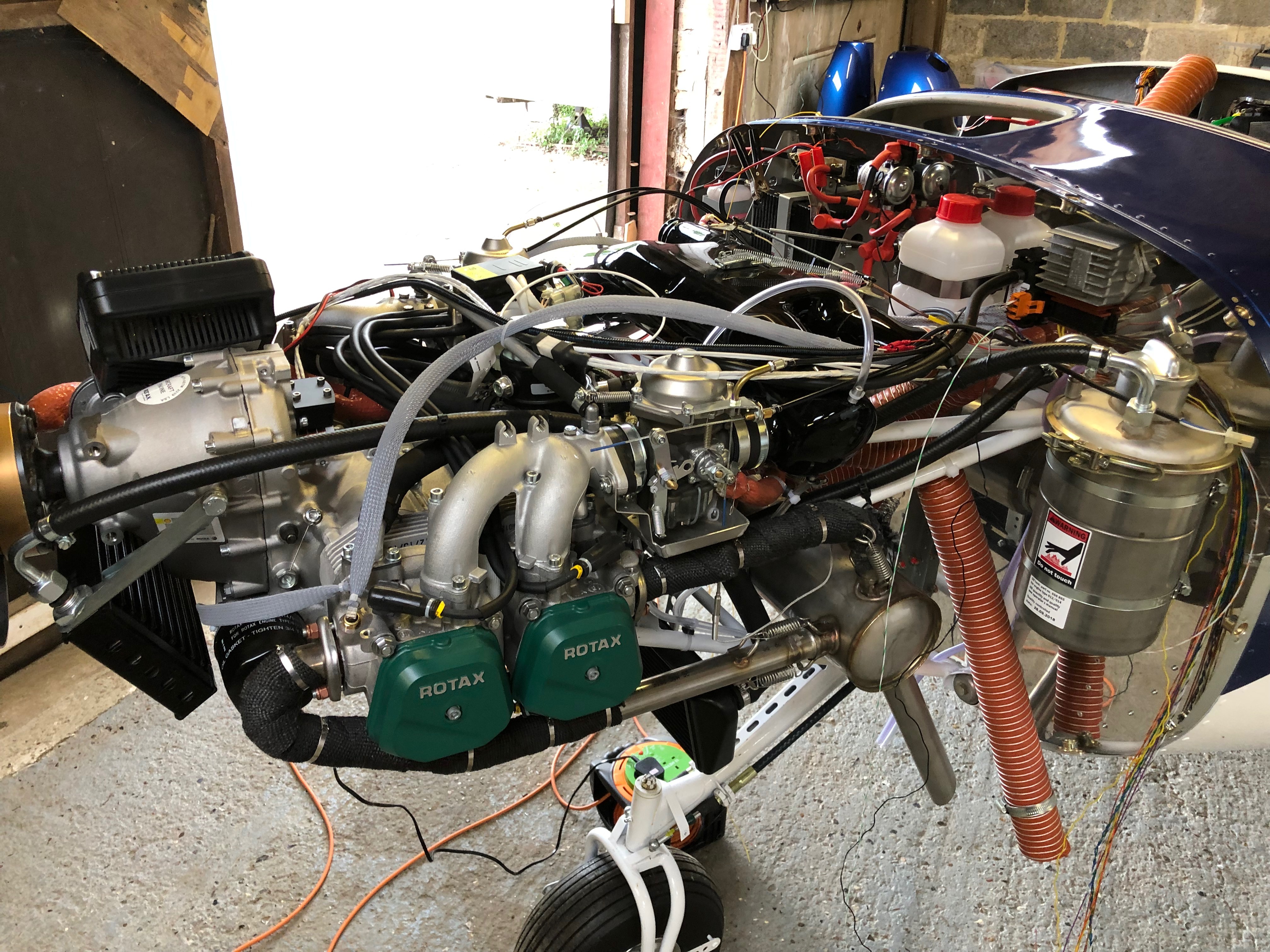
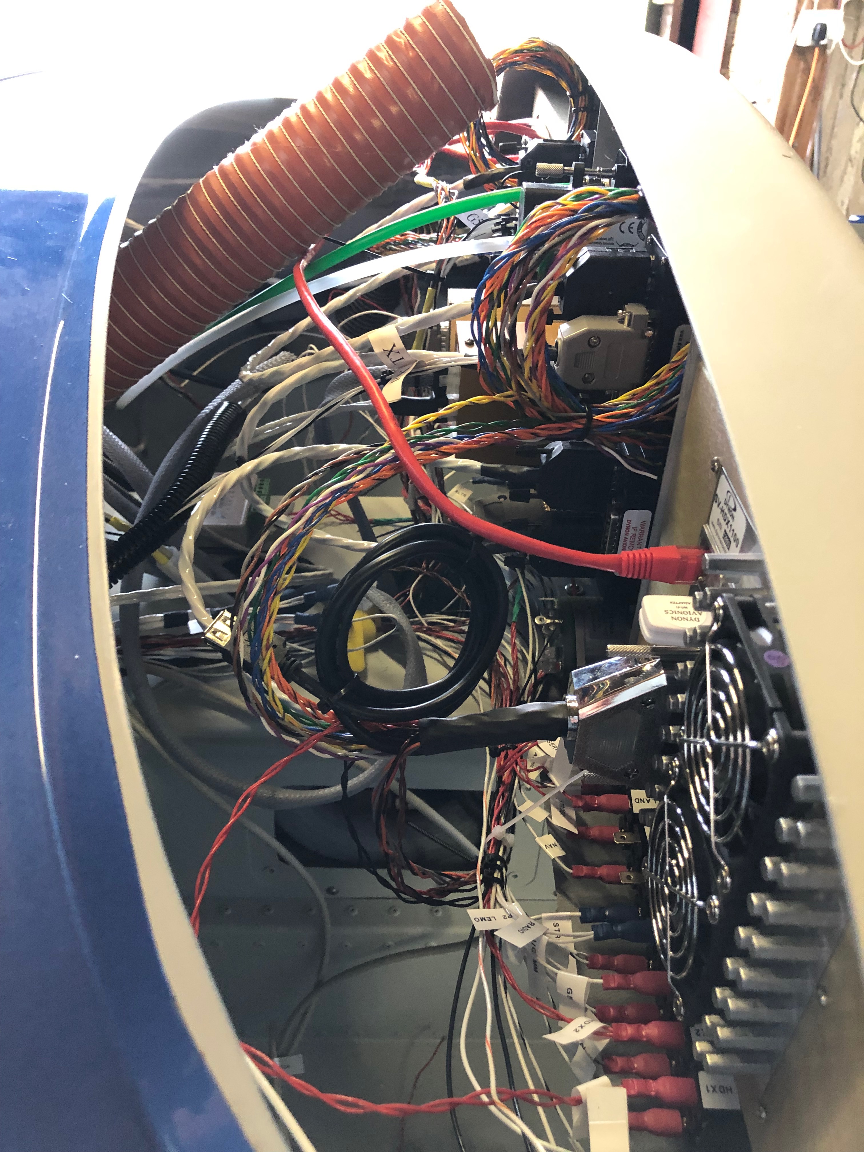
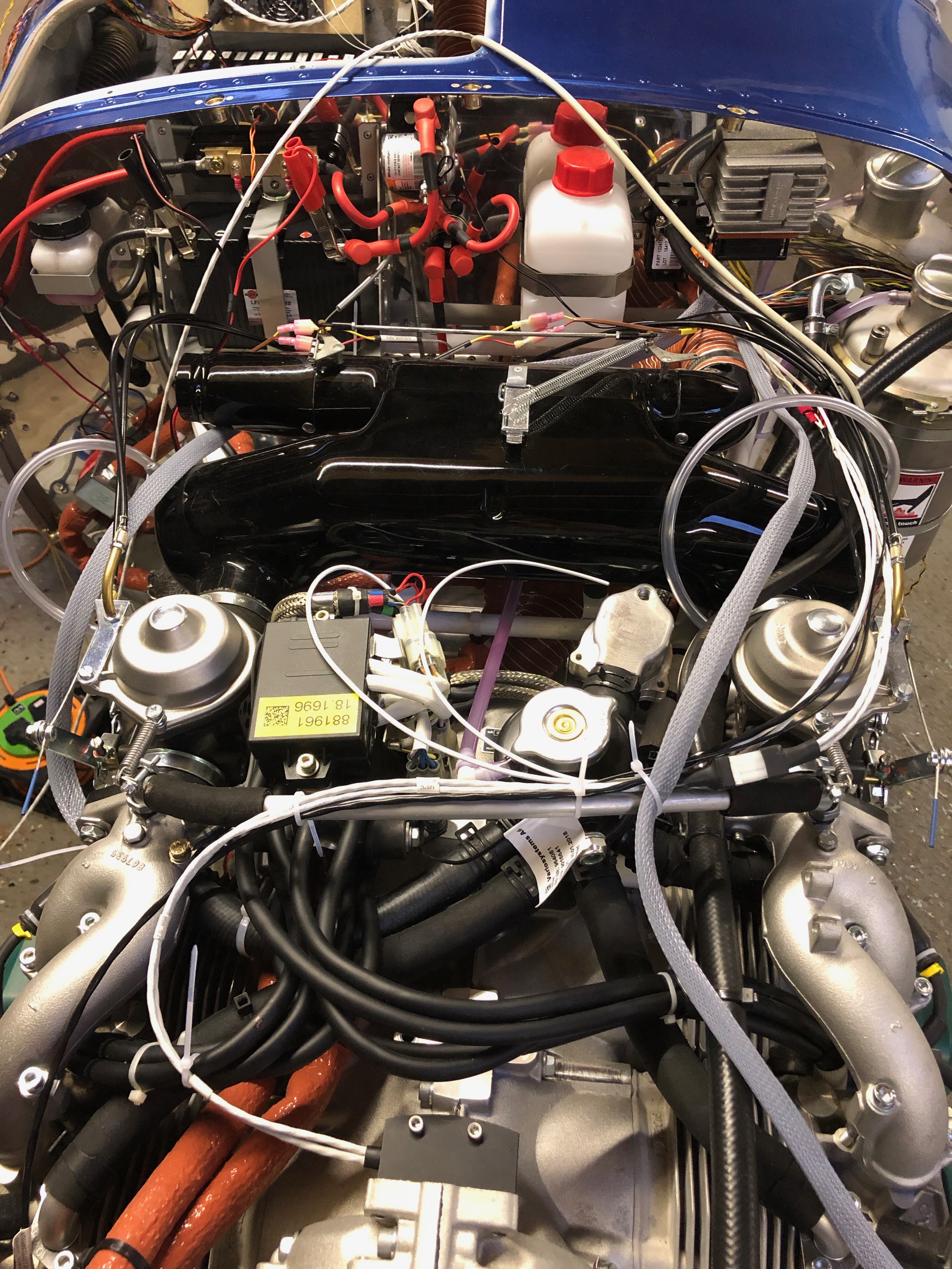
Time to wire up the power side of the electrical system. I’m reusing the wire that I have leftover from the other circuit wires that were trimmed back. There’s plenty to do the job although not a unified colour as long as they are labelled it will be ok.My new friend. A Dymo Label Manager 200 that I bought some years ago. It’s been invaluable and luckily I managed to get some label cartridges.The +ve bus with 11 of the circuits completed.The circuit breakers connected, some tidying will be required but it’s mostly complete.The complete panel powered up for the first time. The system shows a 7 amp power drain which is roughly what I had calculated.My DPD delivery was a day late but got delivered at 10am so I could get on with the wiring of the Transponder and Radio with the coax.The radio coax cable runs through conduit in the fuselage and is terminated with a TNC connector that I’ll do tomorrow.With all the cables protected with sleeving or conduit and secured in place I can fit the interior trim.The rear of the cabin. I’ve checked the radio/headset loom and it works fine so I need to mount the LEMO headset connectors and then I can fix the interior panels.Right side of engine. All the sensors are connected except the Tachometer, soft start module, magneto wires.Left side of engine. Looks a bit busy but with a bit od tidying it will look a bit neater. Quite pleased with the progress so far.
Music: The Pretenders – They were the support to Fleetwood Mac on Sunday at Wembley. I’d forgotten how good their music was!
Time for a short break from wiring but not for long before continuing the battle of the wires!
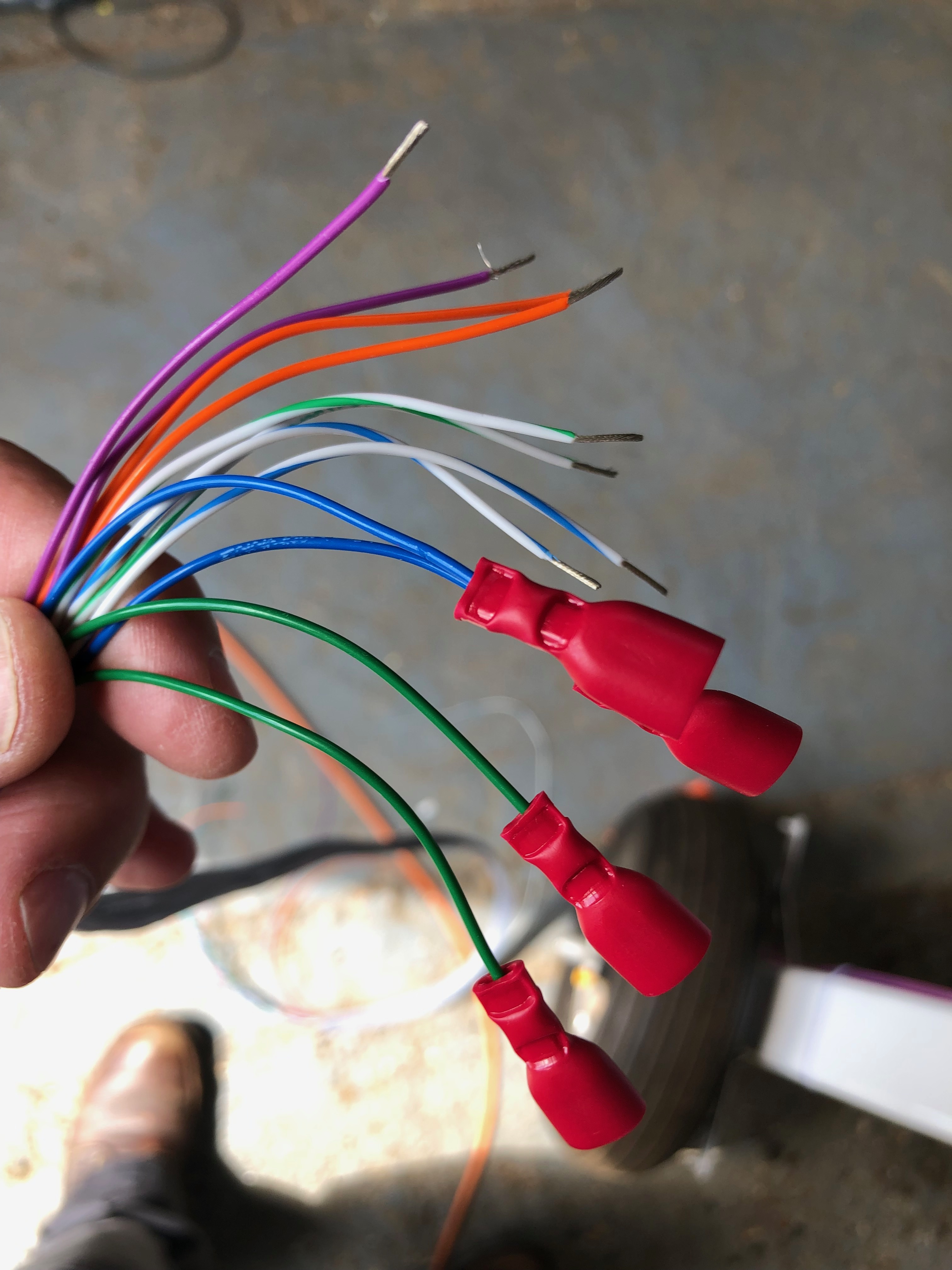
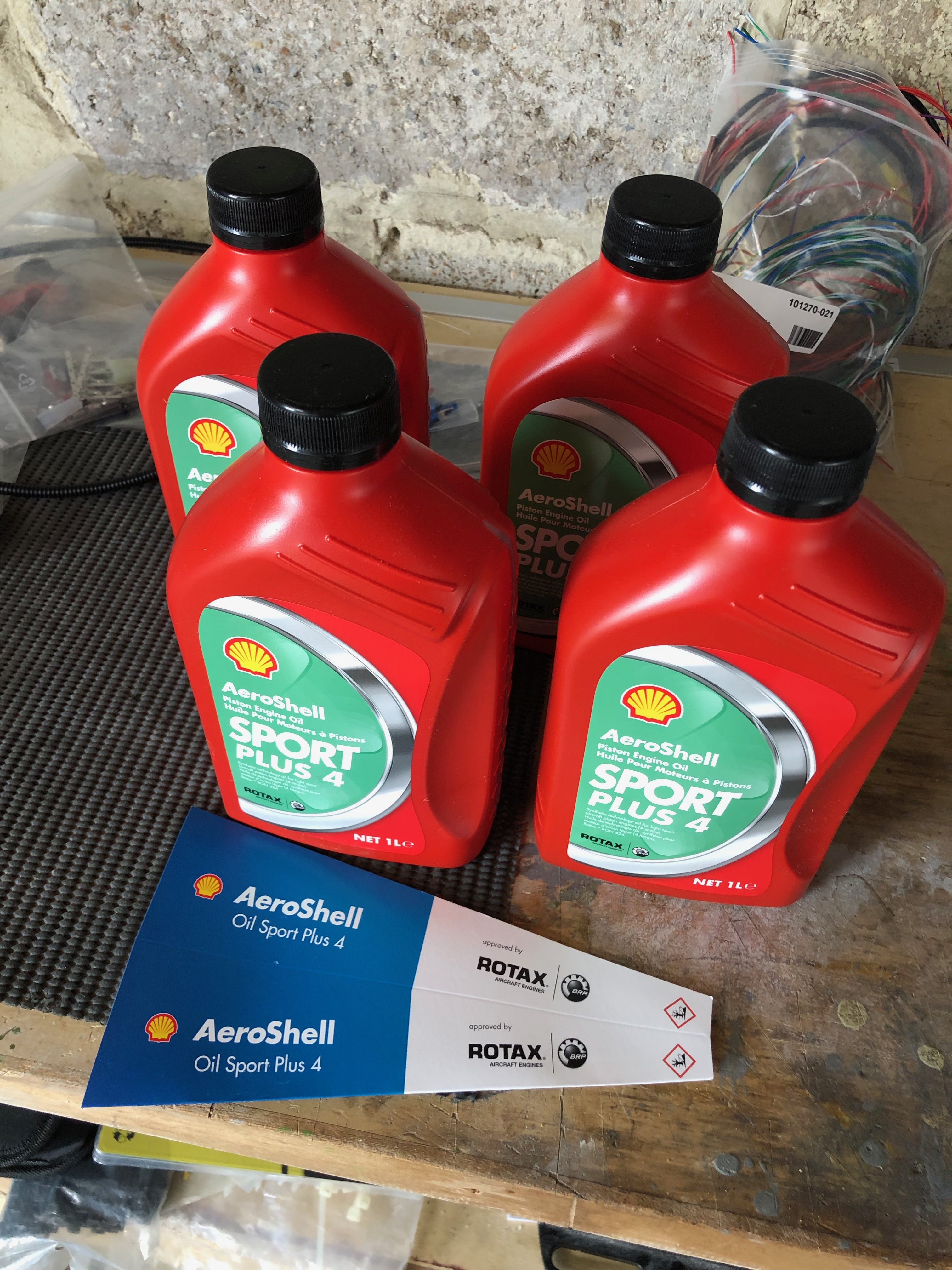
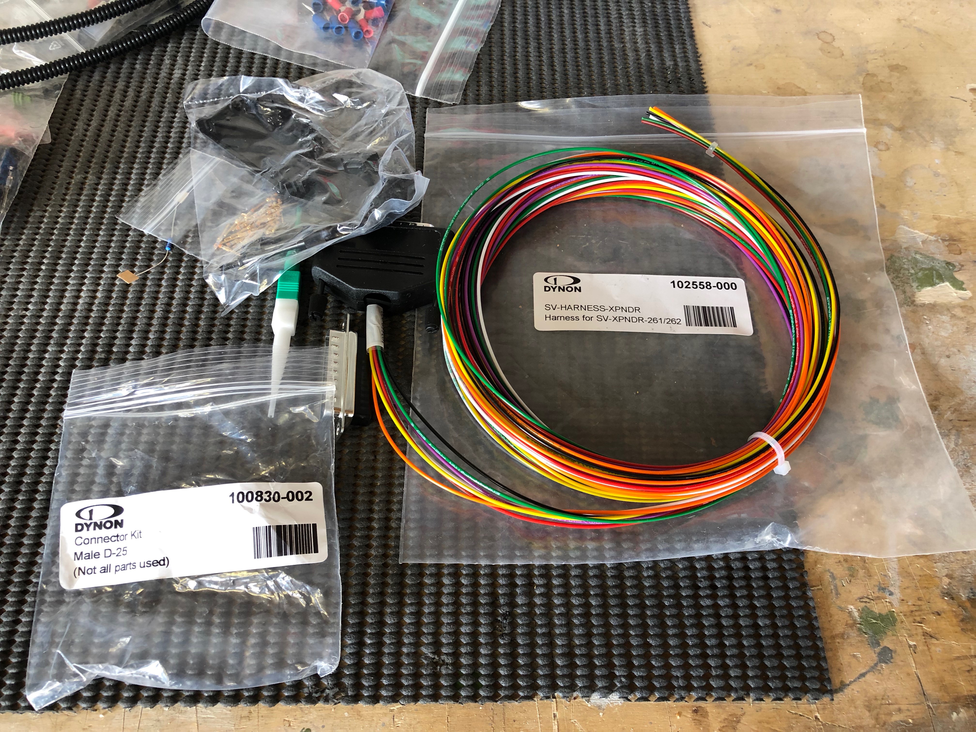
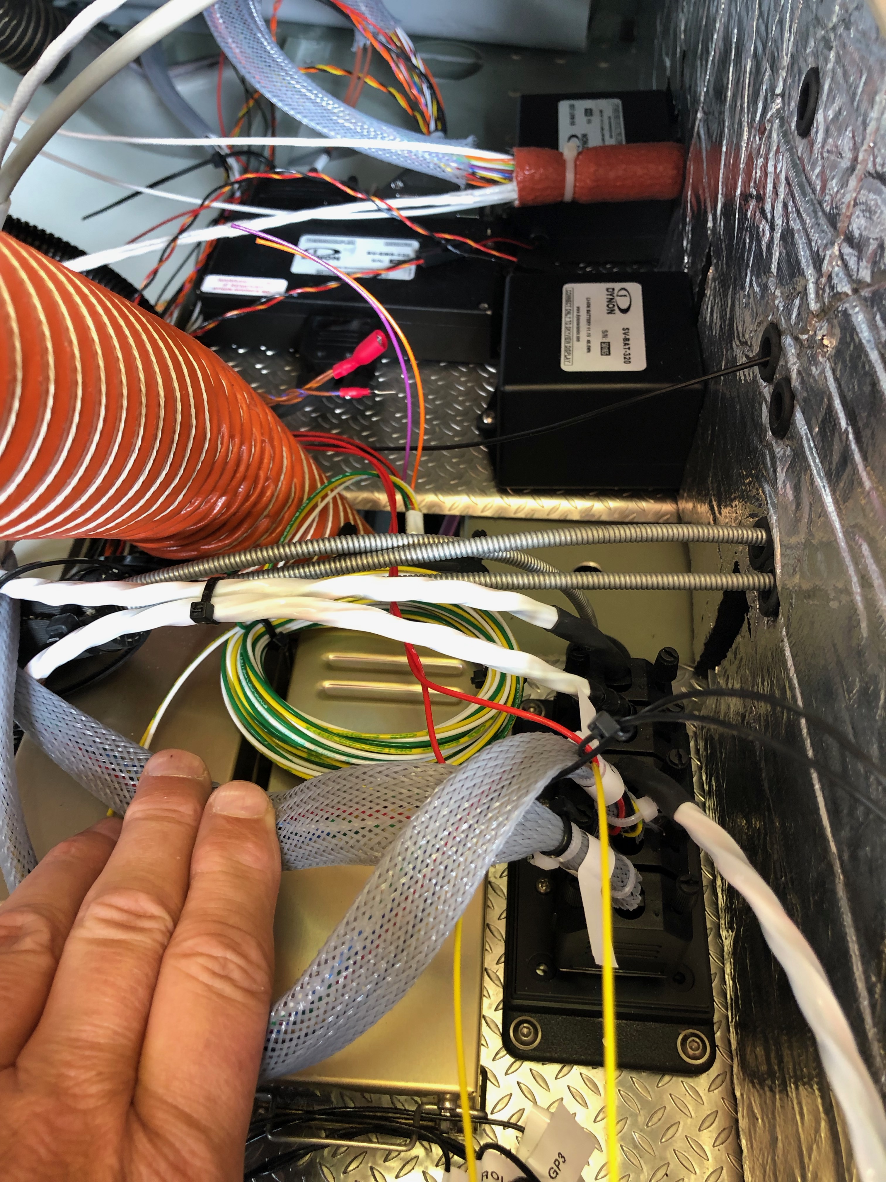
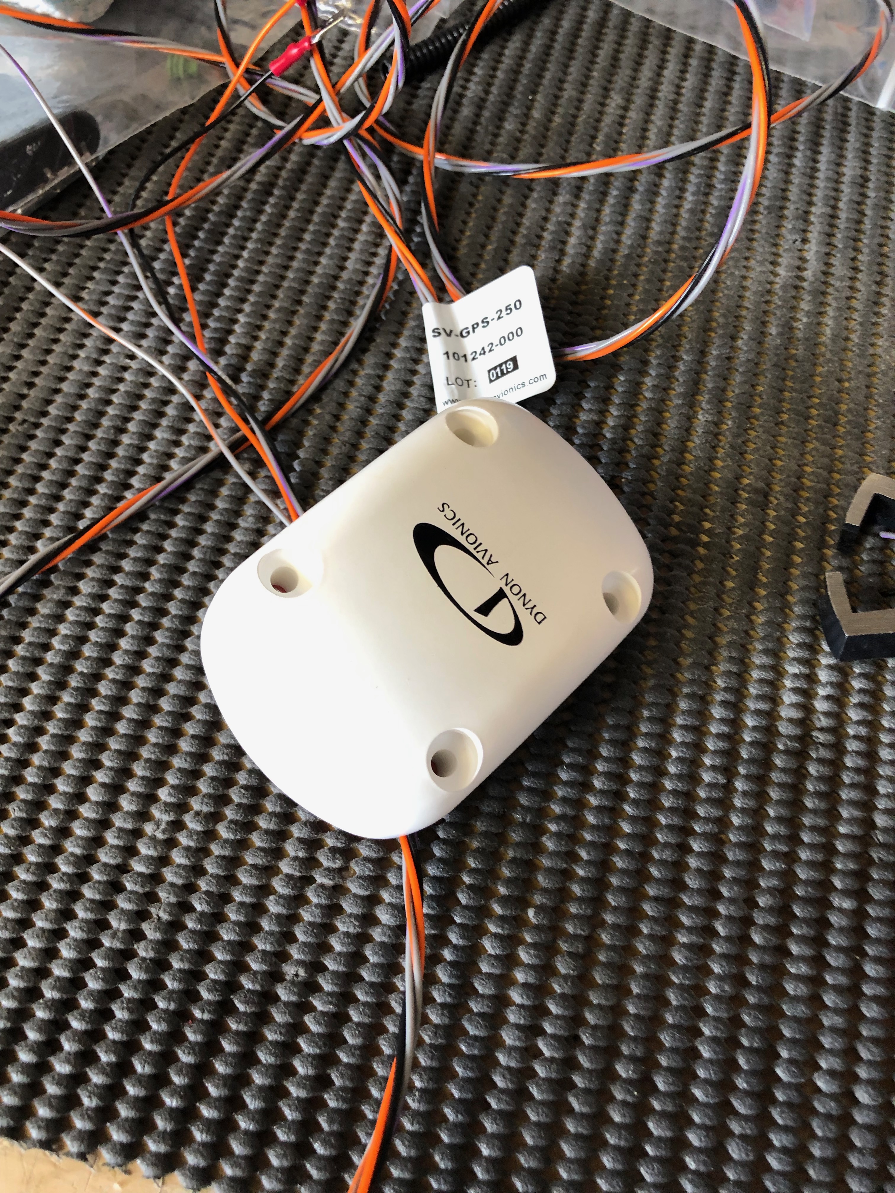
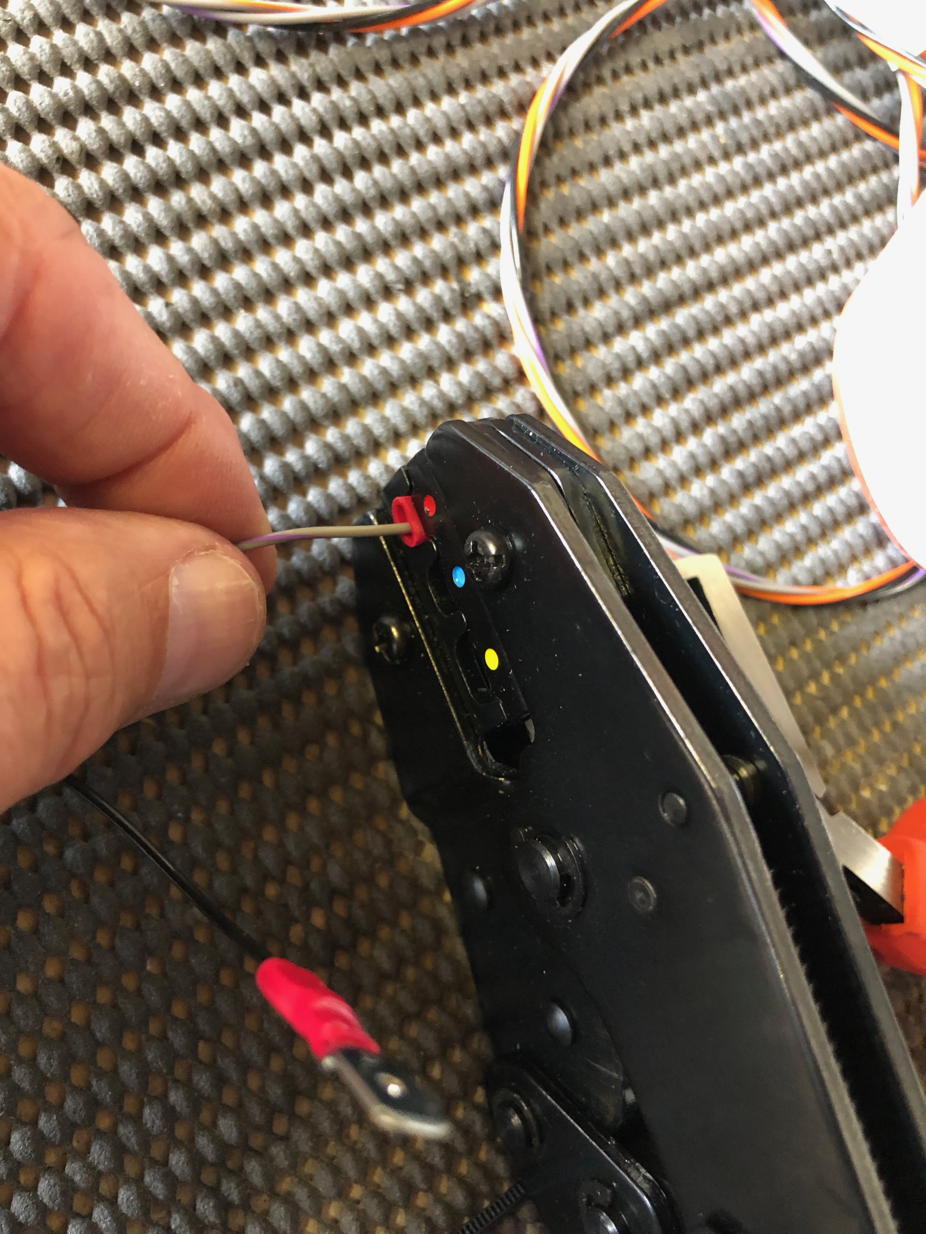
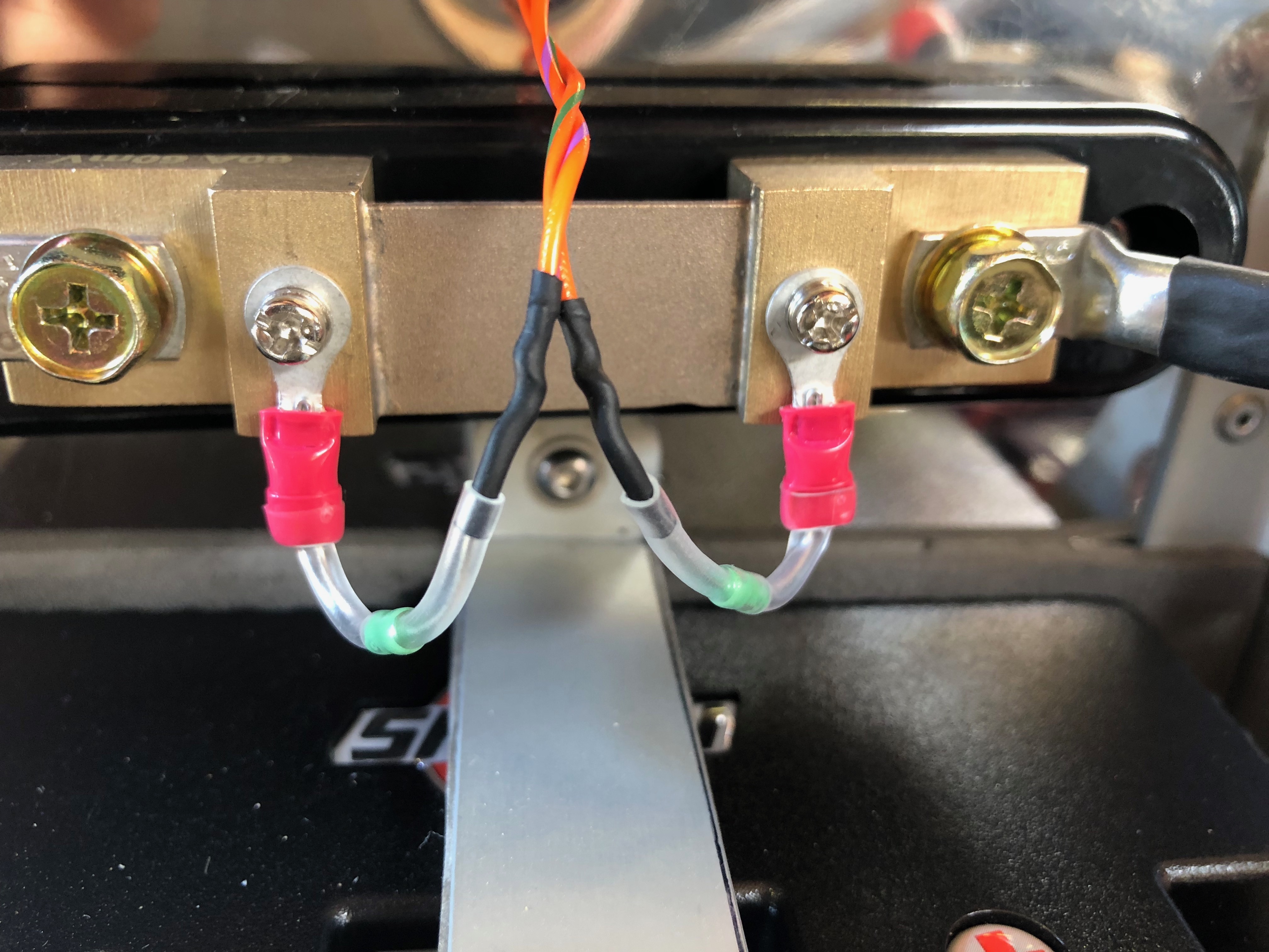
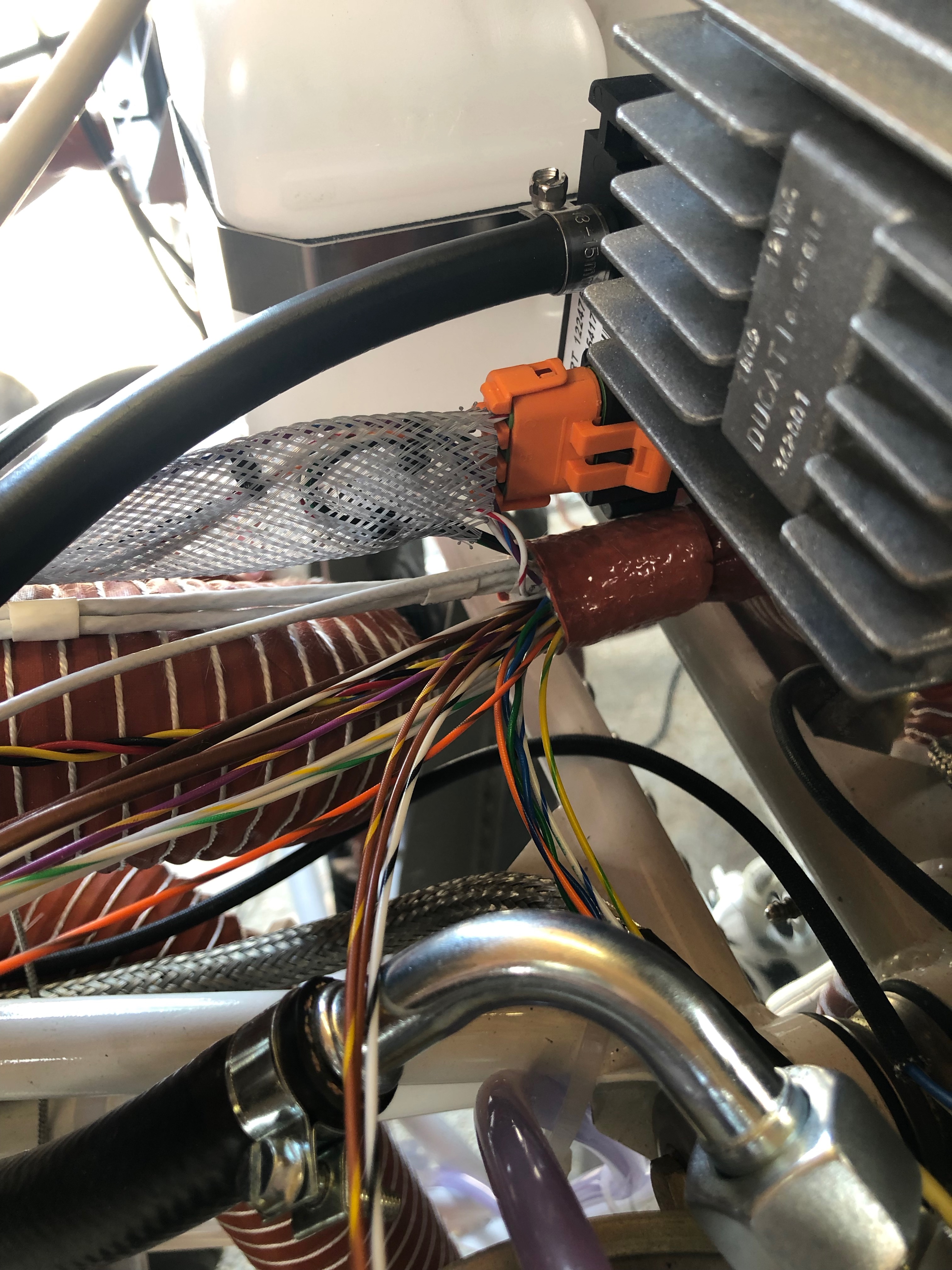
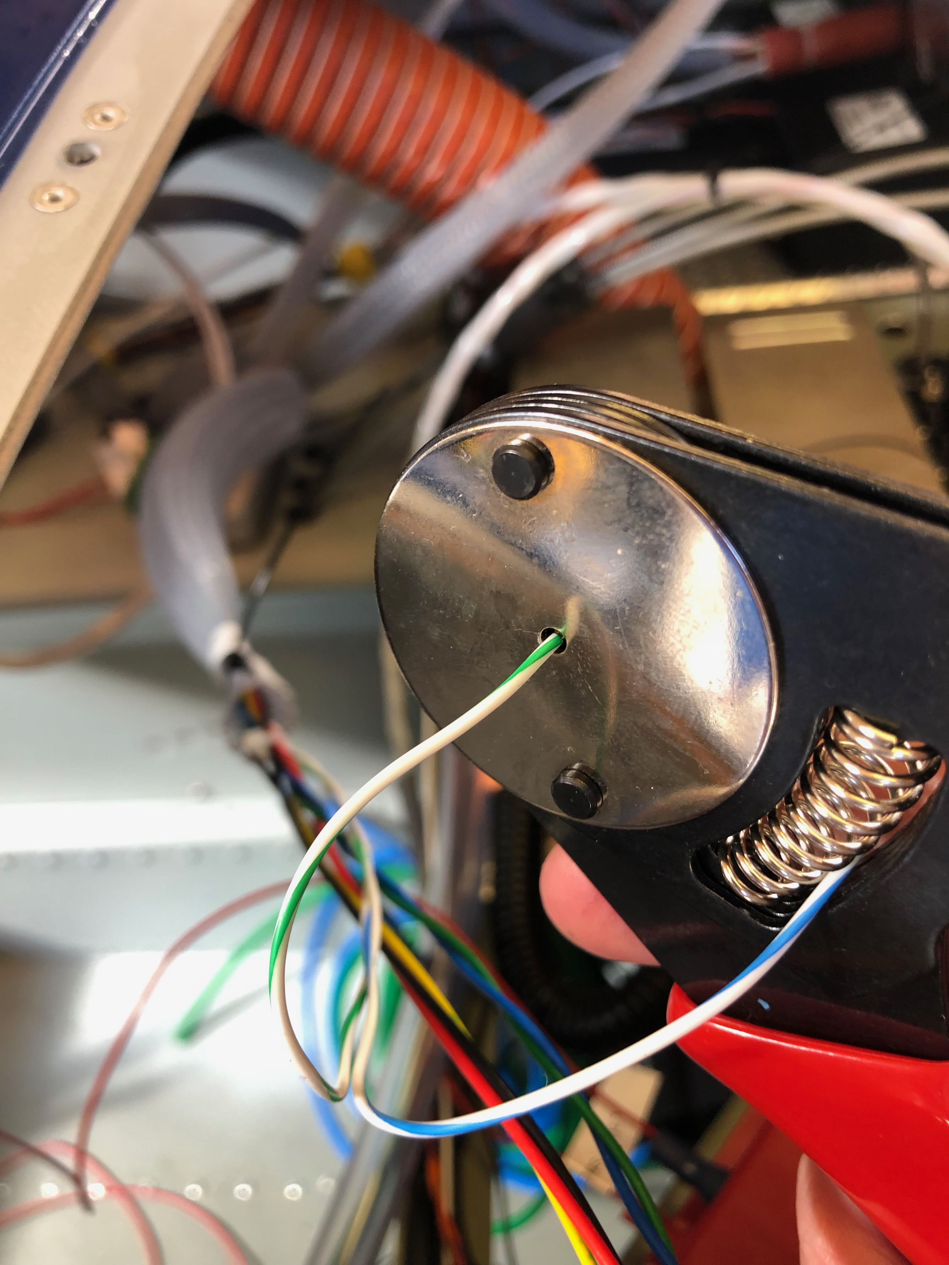
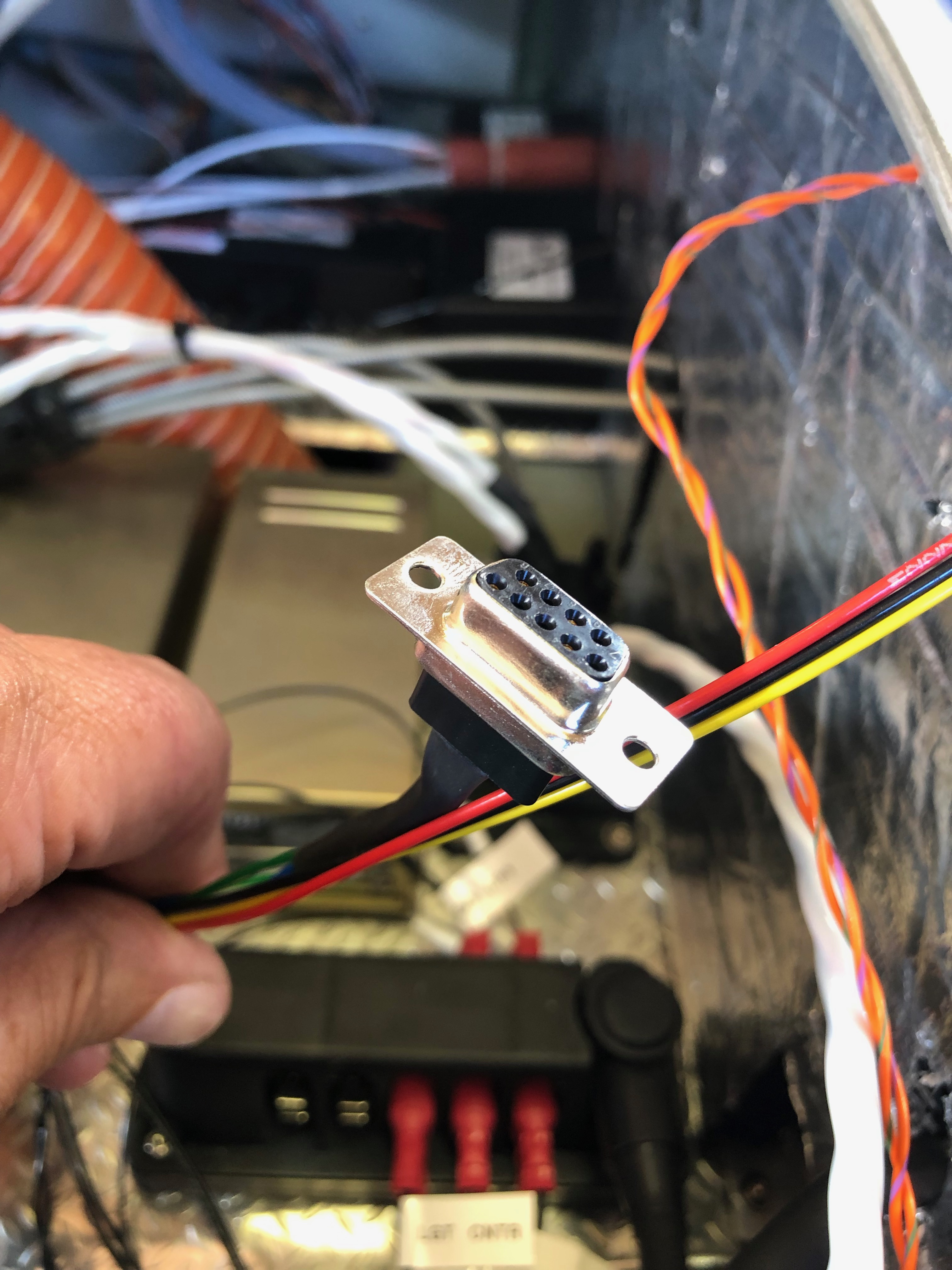
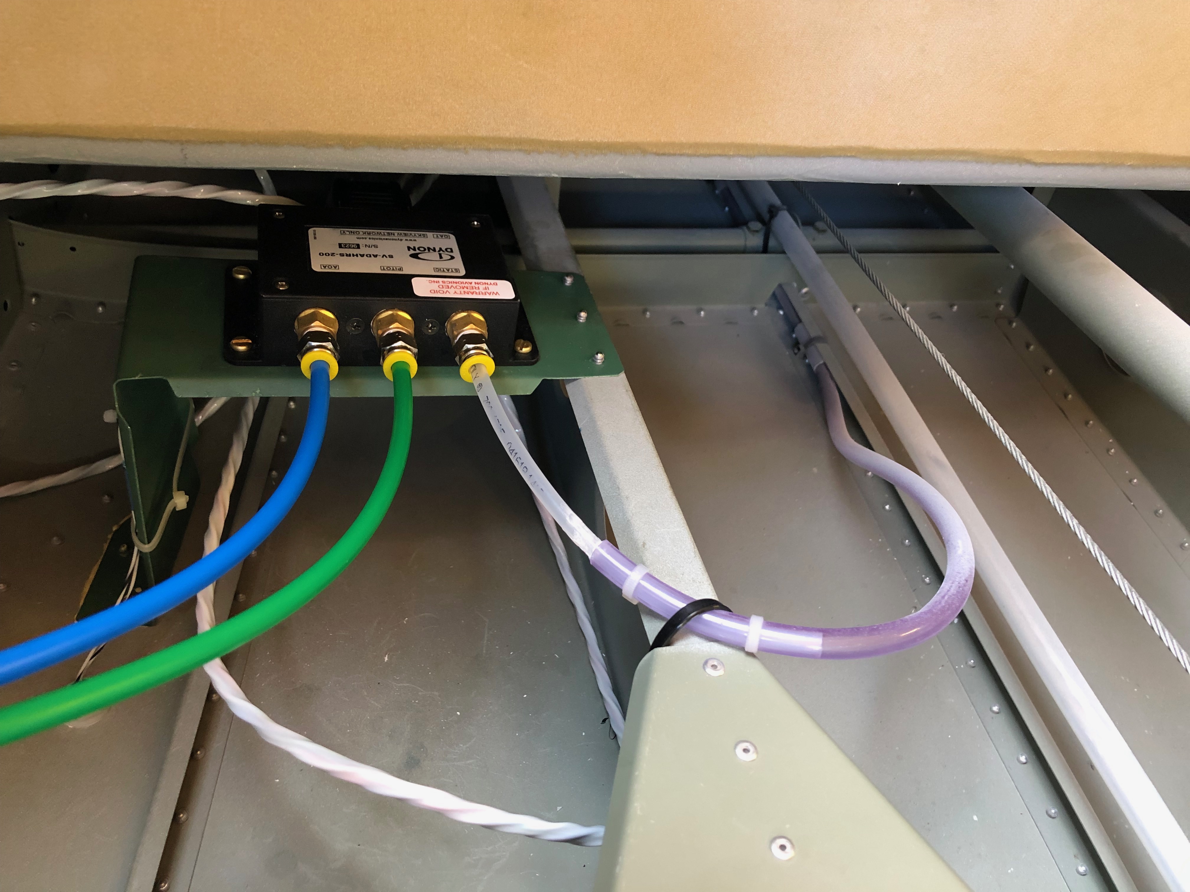
The Rotax engine comes with 4 litres of Aeroshell oil which I thought I’d add to the oil tank as a short break from wiring!I managed to get 3 litres in the tank but I will need to add more when the engine has been turned over a bit as there are a lot of empty oil pipes at the moment!After that very short break it’s back to wiring. This is the transponder loom which is a bit overkill for my needs. As you can see by the coil of wire there is a lot of unused wires but and a lot more has been trimmed from the length of the wires that are used! Once I had checked that it worked as expected I cut the unused wire off and covered the unterminated ends with heat shrink.Before adding a GPS receiver the SkyViews have no idea where they are in the UK, in fact they think they are in the USA! So I’ve taken the power and serial data leads from both SkyViews, spliced them and will connect them to the GPS. There’s a lot of cutting of wires and terminating them, mostly with fully insulated spade connectors using a special crimping tool.Once the GPS is connected a check is made on the connection to make sure it’s not reporting any errors and picking up satellite receivers ok..…and if by magic the SkyView now knows it’s in the UK! The system is reporting height and position correctly from my checks. If you look at the slip indicator you can see that its not in the middle and that’s because the ADAHRS isn’t quite level. There isn’t an adjustment that can be made to correct this so I’ll shim the unit.I’ve positioned the aircraft on a piece of level ground and I’ve shimmed the unit to make sure that it’s level and reporting correctly which it now is.
Music: Fleetwood Mac – Saw them in concert at Wembley last night. A little treat from Karen – Absolutely fantastic!
The wiring continues, after each circuit is wired up a check to see if it’s working as expected. All good so far!
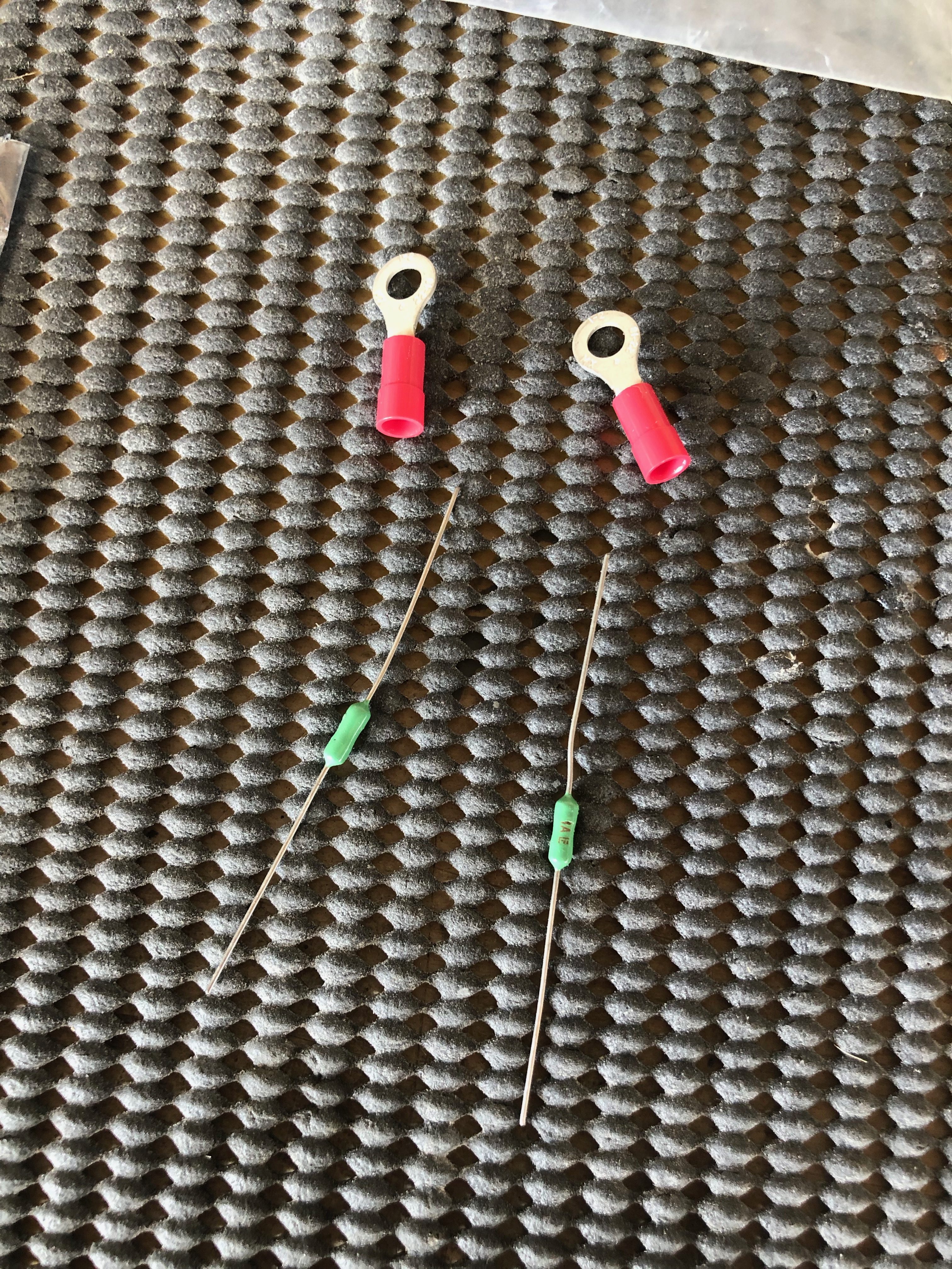
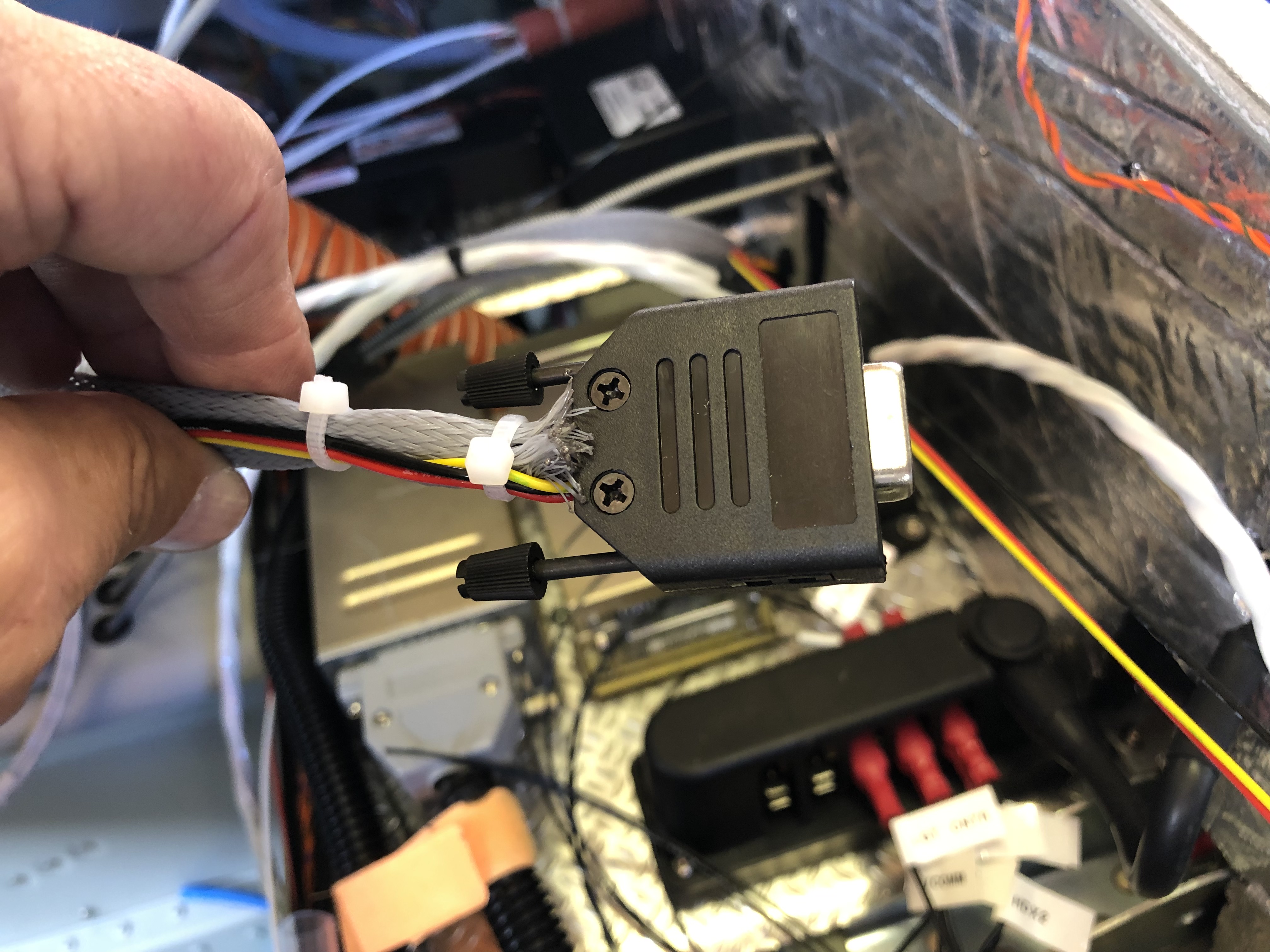
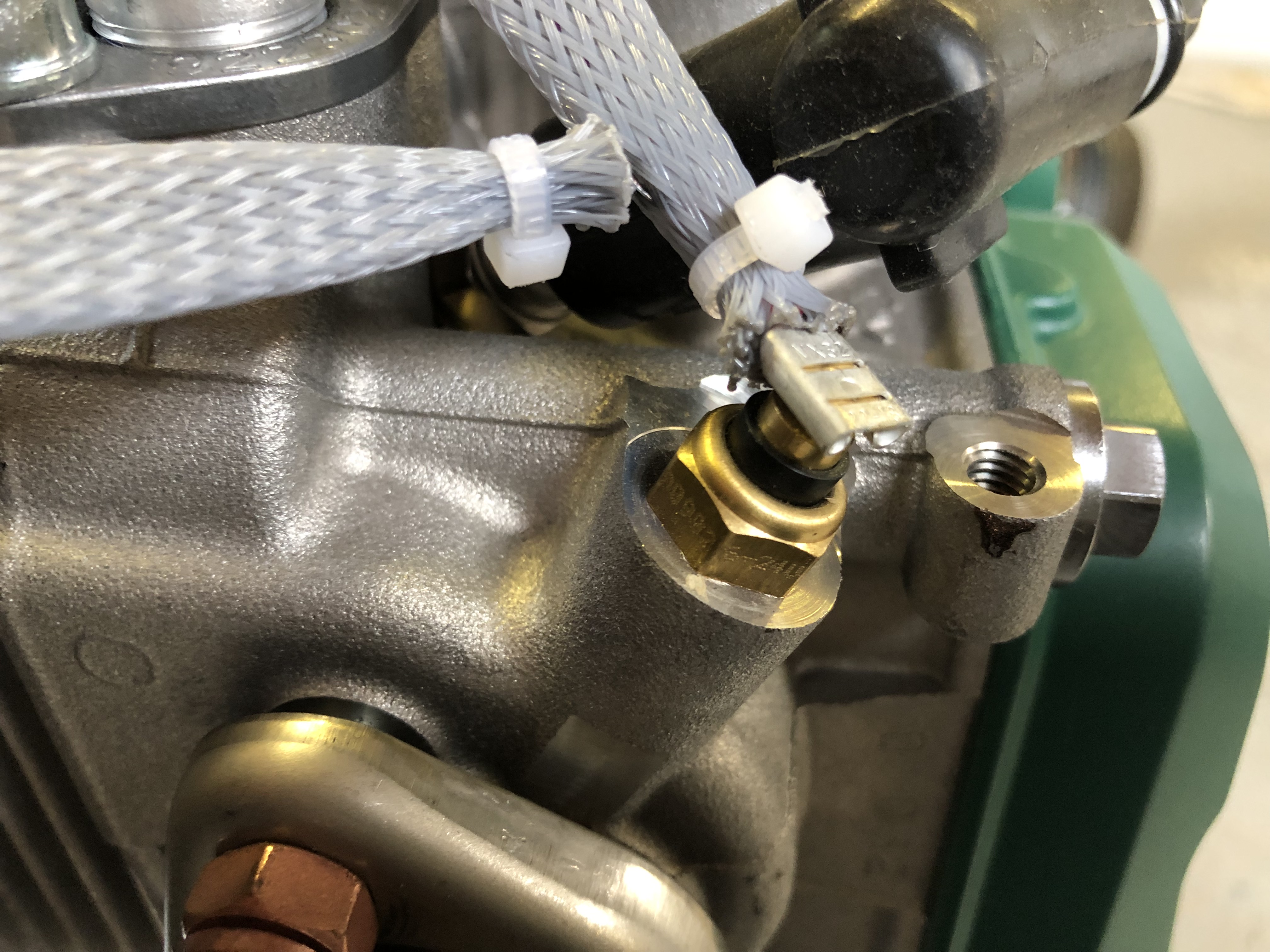
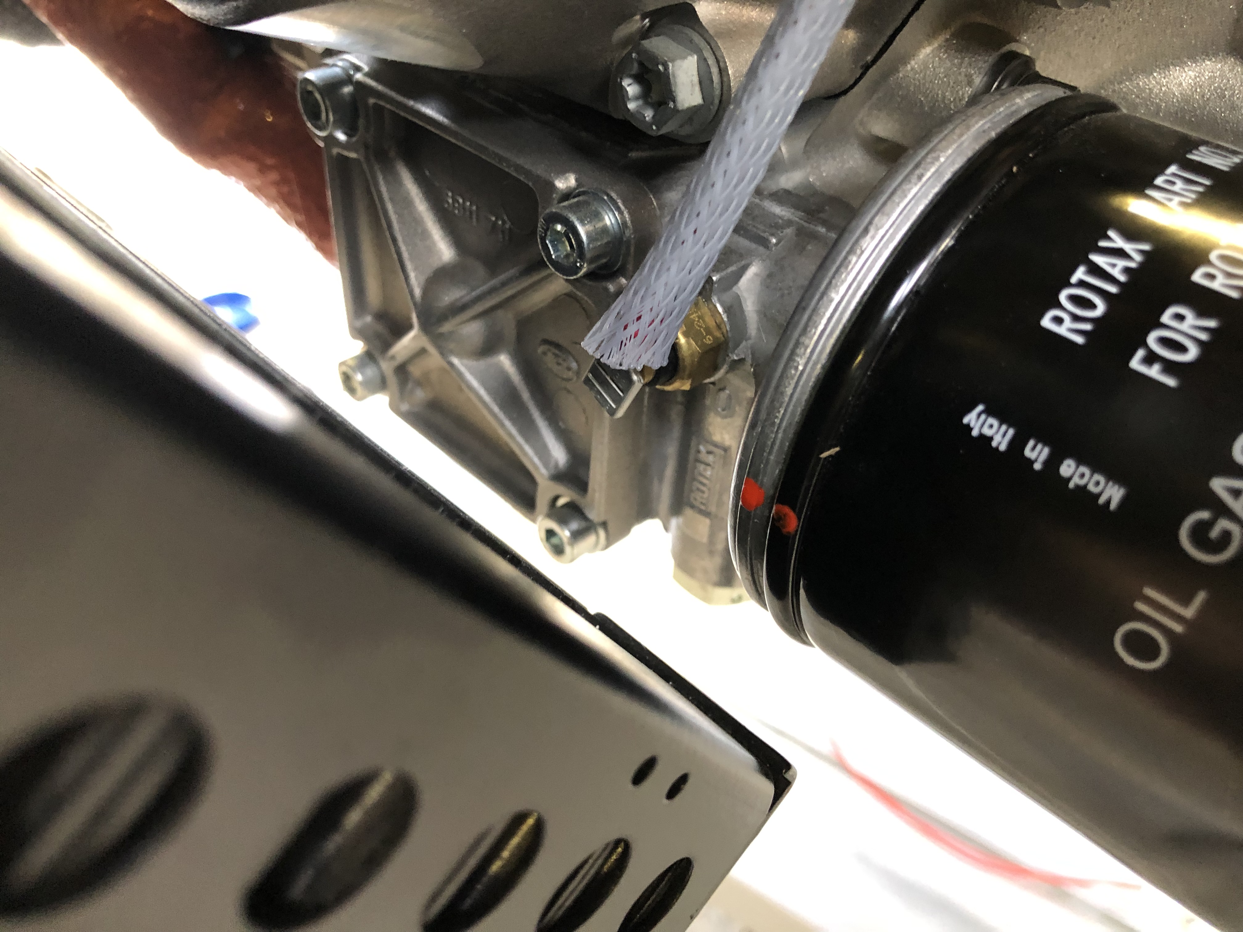
As mentioned previously I need to protect the SkyView from a surge from the Amp Shunt so I’ve purchased some 1 amp inline fuses. They are very small…… and make for a very neat protection solution when positioned inline.With all the wires ‘under the bonnet’ it’s difficult to make it all tidy… …but I layout all wire first to see where best to route them before trimming to correct length and terminating. All these will need to be secured too with stand-offs as required.The servo looms are next. I’ve installed the looms as far as the cockpit and now need to terminate each wire and make up the connector. It requires crimping the pins on each wire with a 4 way crimper.After crimping they are inserted into the D9 block……and the backshell is added. Fairly straightforward but you have to make sure that the crimps are secure. There are two of these, one for roll and one for pitch. Once made up they are plugged onto the SkyView network hub.Next up is to finish off the engine sensor connections. The correct pinout from the D37 connector is identified and the wire routed as described before trimming to the correct length and terminating. In this case a uninsulated spade connector that slips over the sensor connector. This is the LH CHT sensor……and the oil temperature sensor.A quick check that everything is working. The CHTs, EGTs, Oil Temp, Fuel pressure, Oil pressure, Voltmeter, Ammeter and autopilot have now been completed and work as expected.
A few jobs today. Bond the switch plates to the panel, start populating the panel with switches, mark and drill the ignition switch hole, create the looms for the servos and solder to the respective servos.
The panel cutting is largely complete now with just some USB data and power ports to add and an ignition switch. I’ve sprayed it with the paint matched to the interior so it’s ready to have the switches added.To ensure that the spacing was correct I marked and drilled the holes in a piece of 20 x 1mm aluminium and then drilled through the panel. This is now bonded to the back of the panel to give the switches a solid feel during operation. I’ve riveted on a couple of spade tabs to the end of the strip just in case I need to use them for earthing.The switches are installed and tightened with a 14mm ring spanner. Have to be careful here to line them up correctly and make sure that I don’t mark the paint!I’m still awaiting the arrival of my ignition switch that’s on its way from Germany but luckily Ian had one that I could use to get the positioning right and drill the hole. Now they are in I can leave it to set before installing the circuit breakers.Now onto creating the look for the autopilot servos. Dynon sells a servo wiring kit with 20′ of multicoloured wire of the correct gauge, it includes 2 female and 1 male D9 connector. There’s ample wire to make 2 looms from it so I’ve cut it in half and bundled the wires together in readiness for soldering to the servos and terminating with a female D9.There’s a few things that’s important to remember when soldering; 1) Match the colours. 2) Make sure you slide on the heat shrink tubing before you start soldering. 3) Mark each end of the loom so you know what wires you’re working with. Soldered and protected. The final bit is to slide another piece of heat shrink one the bundle to keep it all together and…protect the loom with some conduit. I’ve decided to use split conduit from the servo to the throttle quadrant and then I’ll use poly sleeving from there to the connector block. One of the things that I’m trying to do here is to keep everything neat and tidy for easier maintenance in the future if needed.
With the delivery of a number of outstanding parts I was able to complete the wing locker and servo operating arm installs.
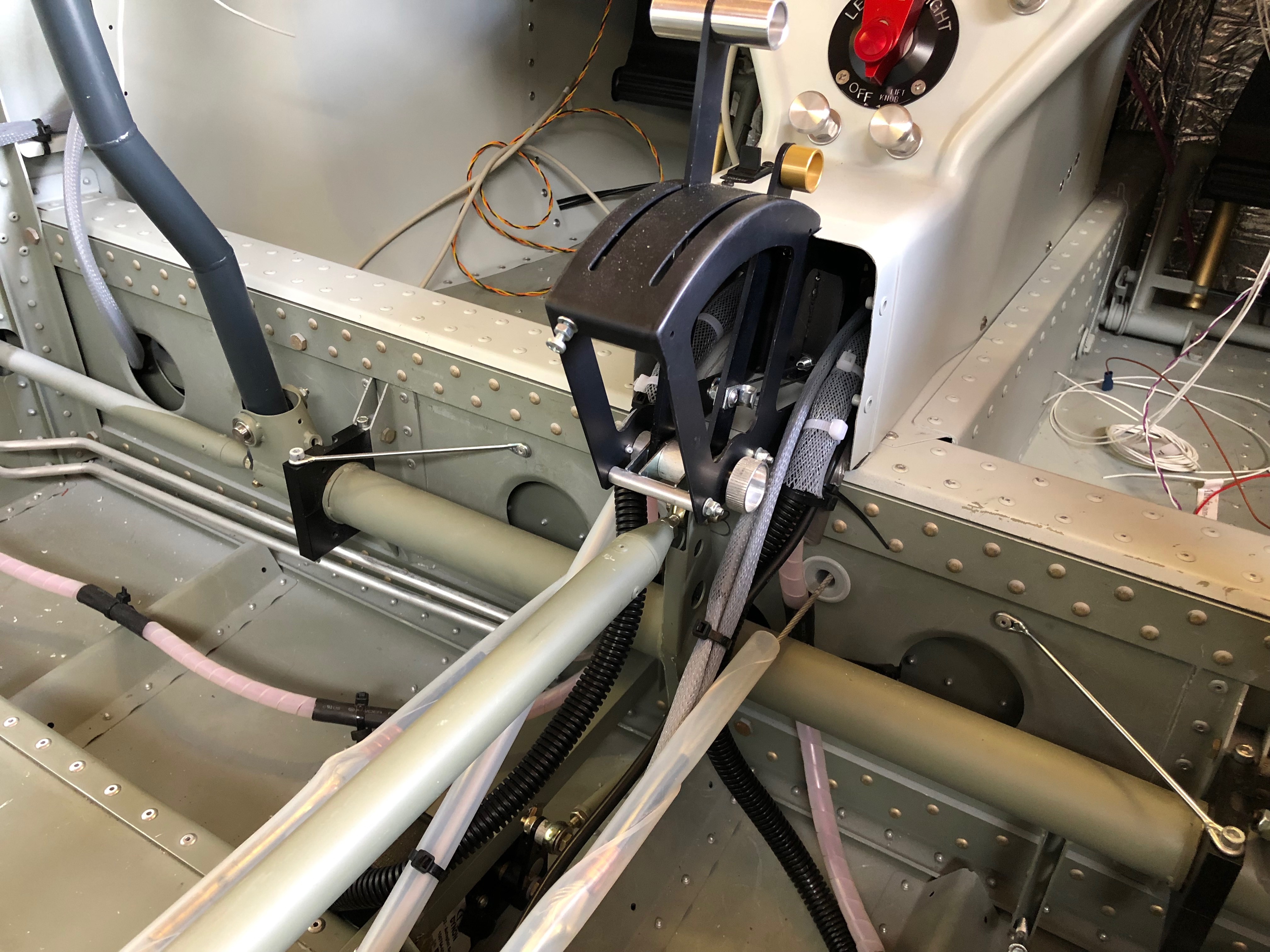
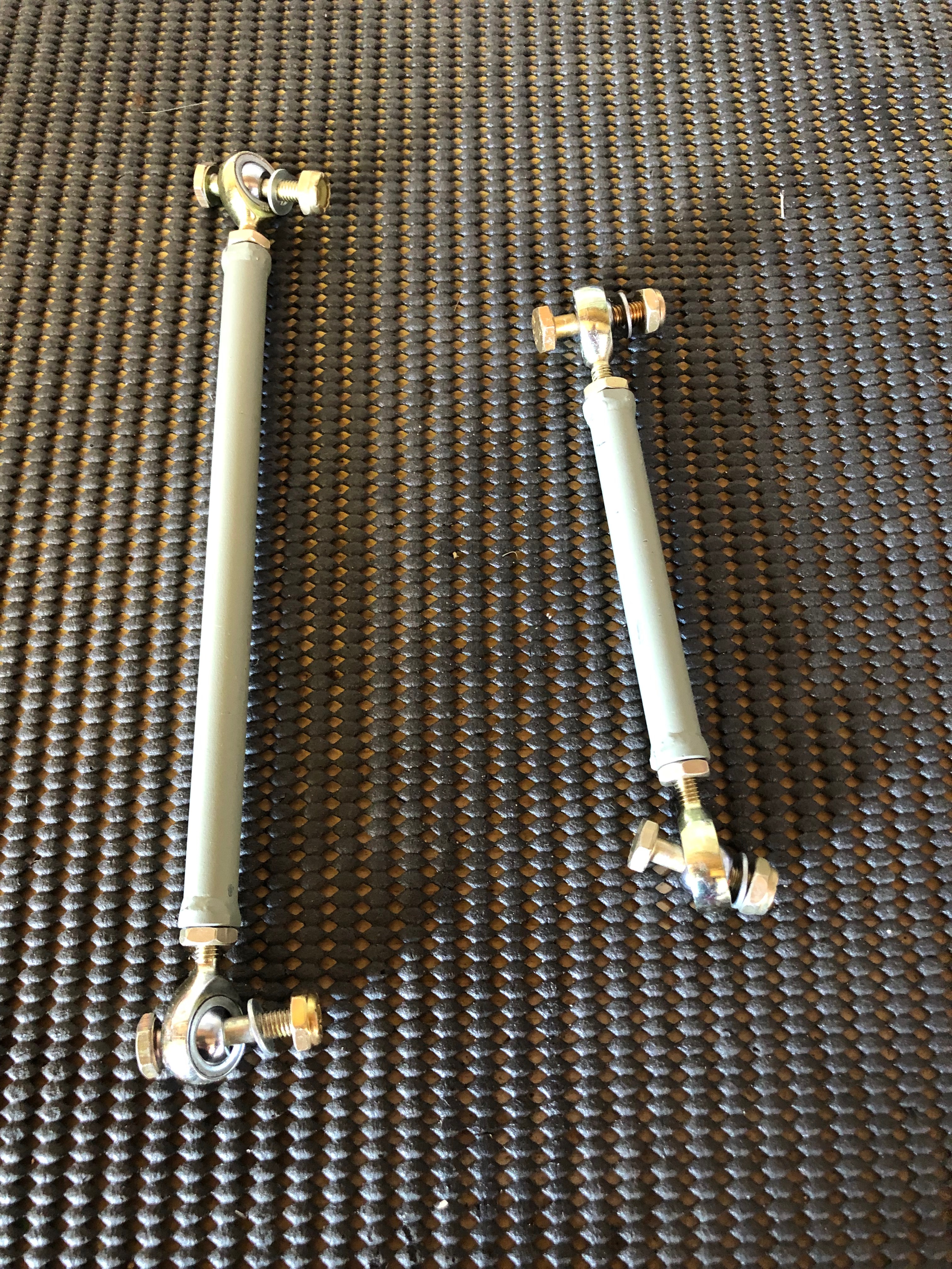
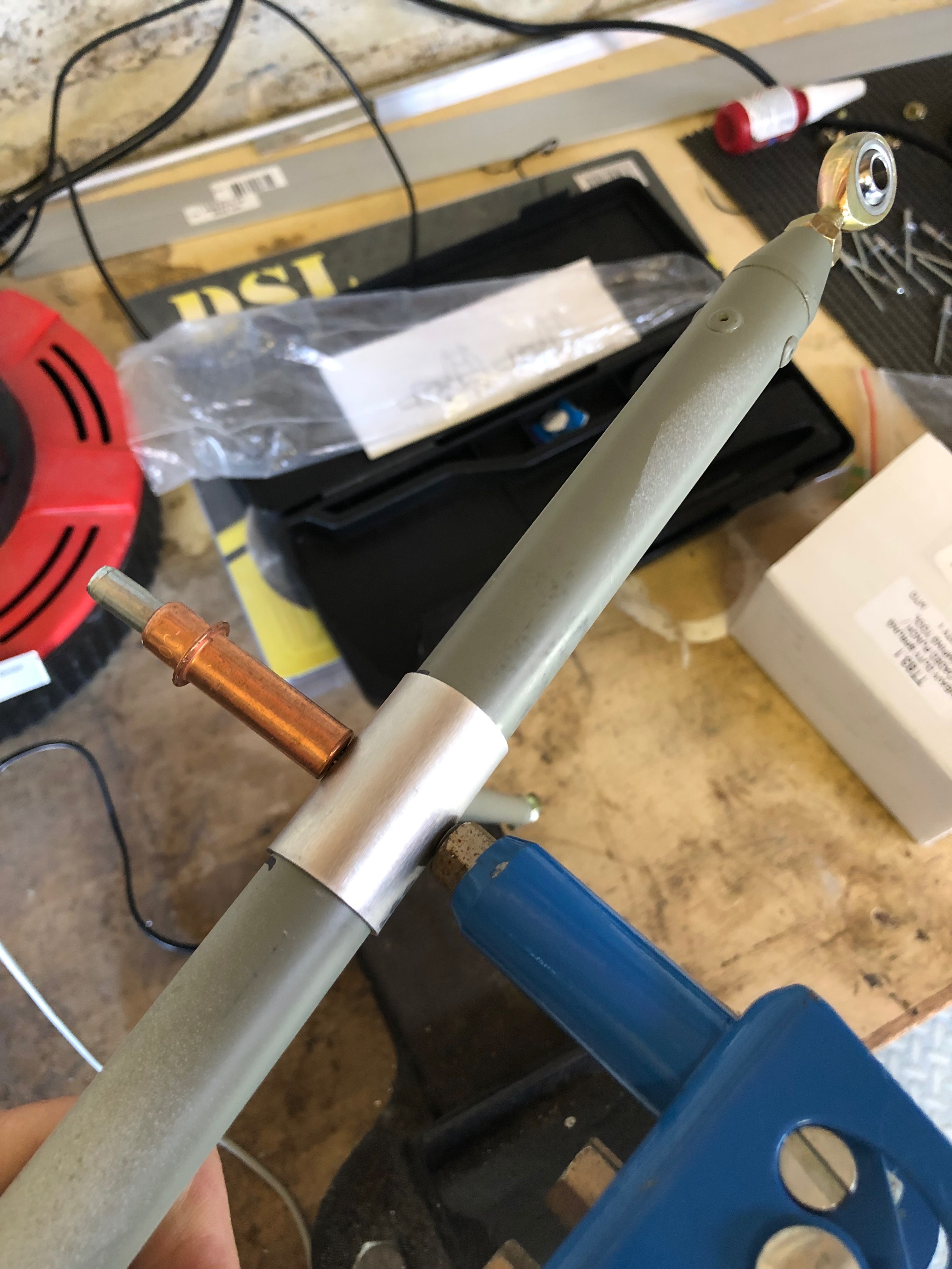
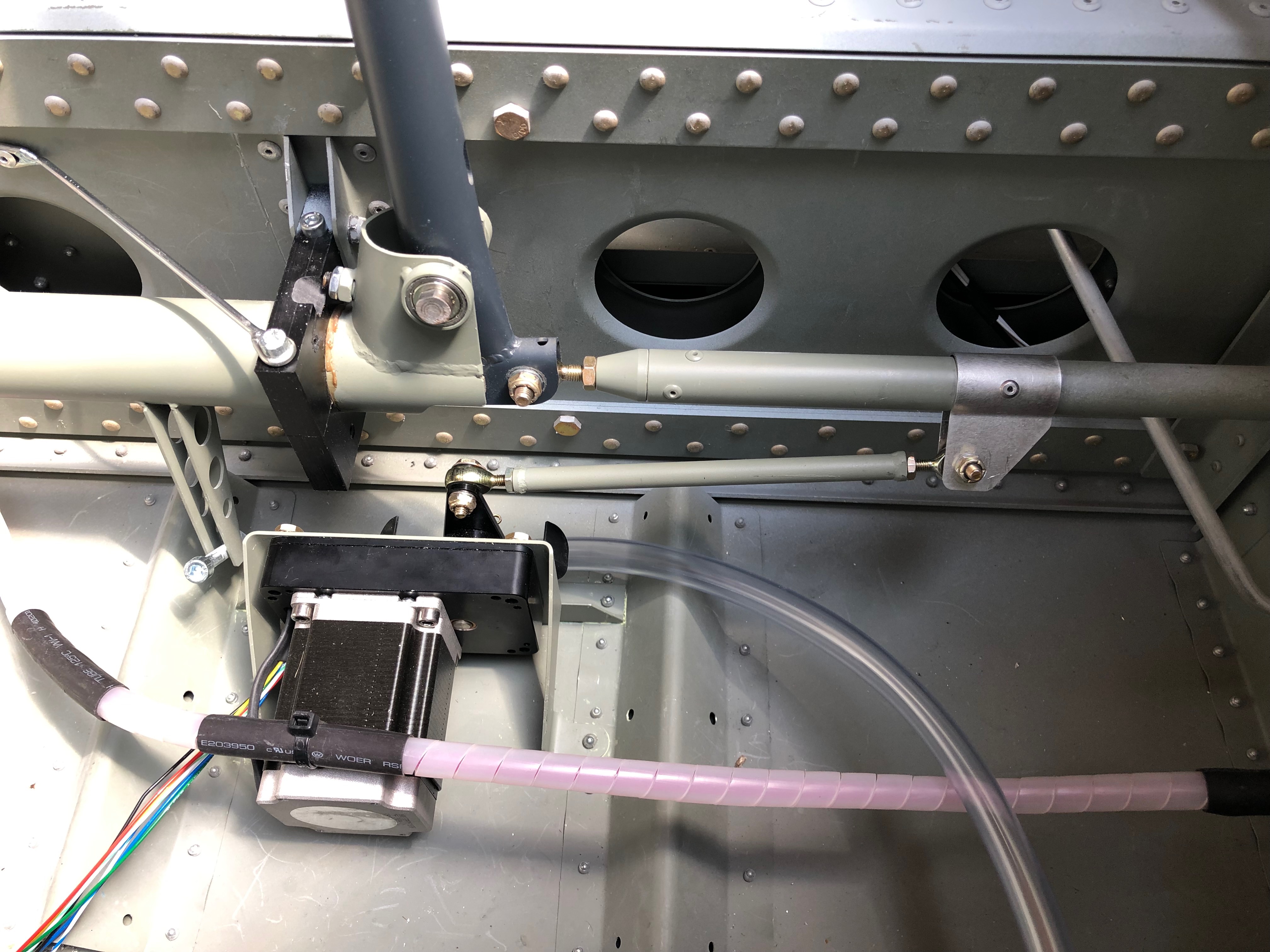
Now I have the fittings for the wing lockers I can finally finish off a long overdue job.The weather-proofing washer is put over the lock barrel and the unit is inserted into the pre-drilled hole…and locked into position with a nut.The locking bar mechanism is fitted onto the lock barrel and held in place with a screw and shake proof washer.The final part of the install is running a rubber seal around the inside edge of the wing locker to make it watertight. The same process is carried out for the starboard wing locker.The wings are now complete!Another item I’ve been waiting for is the servo operating arms so I could finish the servo install.The roll servo is connected to the aileron operating rod with a clamp.attached to the servo arm. The control stick and servo arm are centralised and the clamp position is marked so it can be riveted in place.The only way you can get the aileron control rod out to is by dismantling a lot of the fittings that hold the control sticksThe clamp has two pre-drilled holes holes either side of the clamp that are used as a guide for the rivets. The first hole is drilled and cleco’d in position to ensure it doesn’t moved when drilling the other side.Two 3.2mm rivets are used to further secure the clamp before refitting.The pitch servo rod is a lot simpler to fit. Two AN3 nuts and bolts secure the rod in place and the final adjustment is made once the aircraft is rigged.The roll servo and control arms completed.Final job for today is to start installing the pressure system pipework for the pitot, AOA and static fittings
Music: The Greatest Showman reimagined and Snow Patrol.
Finishing off the insulation installation, first fit of centre console, autopilot servo install and filling brake system with Aero Shell 41.
One quick job this morning now all the other pipes have been fitted is to run a piece of piping from the water expansion chamber to the water bottle.
I have been given templates for the insulation so I can cut them to size without too much effort.
Some notches, cuts and holes need to be made to make sure it sits properly on the firewall.
It’s a tight fit behind the rudder pedals which makes it difficult to handle once the backing paper has been removed.
The final pieces are fitted around the heated inlet.
The finished insulation, hopefully this should reduce noise from vibration of the firewall and the engine.
Now the servos brackets are in position the servos can be fitted. First the roll servo.
It’s very fiddly and would have been much easier to fit the servo to the bracket whilst it was out of the aircraft.
The pitch servo with the movement limiting bracket fitted which stops the motor running over centre. I still can’t finish the installation as there were items missing from the kit supplied to me – very frustrating as I can’t refit the controls until I fit the roll servo arm.
A first fit of the centre console in readiness for the fuel selector. Need to check with the instrument panel in place to check that the flap control cable is long enough to fit on the panel otherwise is will need to be mounted here instead which I would like to avoid.
After fitting the insulation need to reconnect and tighten the brake hoses before filling.
The brake fluid is filled from the bottom so some plastic pipe is wire locked onto the brake calliper nipple so stop it slipping off. The nipple is unscrewed to allow the fluid to flow into the calliper.
An oil can that has been thoroughly cleaned is filled with Aero Shell 41 and the plastic pipe is fitted to the nozzle.
The filling commences after releasing the park brake valve.
When the fluid reaches the brake oil bottle the brake calliper nipple is tightened and the process is repeated for the lefthand side brakes.
Filling complete but some air bubbles are present. They will need to be purged before use otherwise the brakes may not operate properly.
I took delivery of the servo brackets and wing locker fittings after a lengthy wait. Unfortunately bit were missing, again. The servo arm, bolts, washers and some rivets were missing from the servos mounts and the nuts, washers and large screws for the locks were missing from the wing locker kit. It can be very frustrating and delays the build.
Despite this at least I was still able to mount the servo brackets. During the install I found myself like a contortionist whilst I installed the brackets and front trim panels with an air rivet gun.
I spent some time this morning making sure that I can get to all the screws once installed. The cut outs are for the EFIS backup batteries. The insulation is fire resistant and will provide sound proofing too. It is secured into position by a self adhesive backing.
The install consists of 2 brackets one for roll and one for pitch. To install them I will need to remove the controls.
There’s quite a few nuts and bolts to remove including those holding bearings.
The control assembly, sometimes it feels like you’re dismantling the aircraft instead of building it when you have undo some of the work you’ve already done.
Now the area is clear I can start to install the brackets.
The bracket is positioned and 4mm holes drilled through the floor of the aircraft.
From underneath 3 holes are drilled which will further secure the bracket.
Ian Daniels has kindly lent me his air rivet gun and compressor which should make installation a little easier.
Once the holes are de-burred, and anti corrosion jointing compound is applied the bracket is cleco’d in place and riveted from below.
The final bracket installation. Once I have the rest of the missing bits I’ll be able to complete the roll installation.
To enable the installation of the pitch servo bracket 3 rivets need to be removed. The first thing to do is knock the centre hardened pin out…
and then drill the head of the rivet off and then know the rivet out.
The bracket is placed and checked that it’s positioned correctly.
One of the rivet holes don’t quite line up which is surprising but will need to be drilled out to enable it to be riveted.
Ian Daniels come to the rescue again as he lent me this 90 degree drill attachment that allows me to drill the hols for the rivets. There isn’t enough space to drill the holes without this.
The pitch servo riveted in place. Quite please with the bracket installations but they take a lot of time and I’ve still got to re-install the controls!
So I can install the insulation in the door wells I need to install the forward trim as they are riveted in place. It’s a tight fit behind the rudder pedals but they can’t be fitted until after the rudder pedals are fitted as there is insufficient room.
The air rivet gun makes it easier to get to the rivets but because it’s size I won’t be able to use it for all the rivets…
So for some I need to use the hand rivet gun but it’s very awkward to use in such a tight space.
It took some time, longer than expected however the left panel is in…
and so is the right. Tomorrow I will refit the controls.
Following the build of my Bristell NG5 Kit No. 382 Registration G-MLSY