Category Archives: Avionics

Tuesday 25th June 2019

Music: Turin Brakes

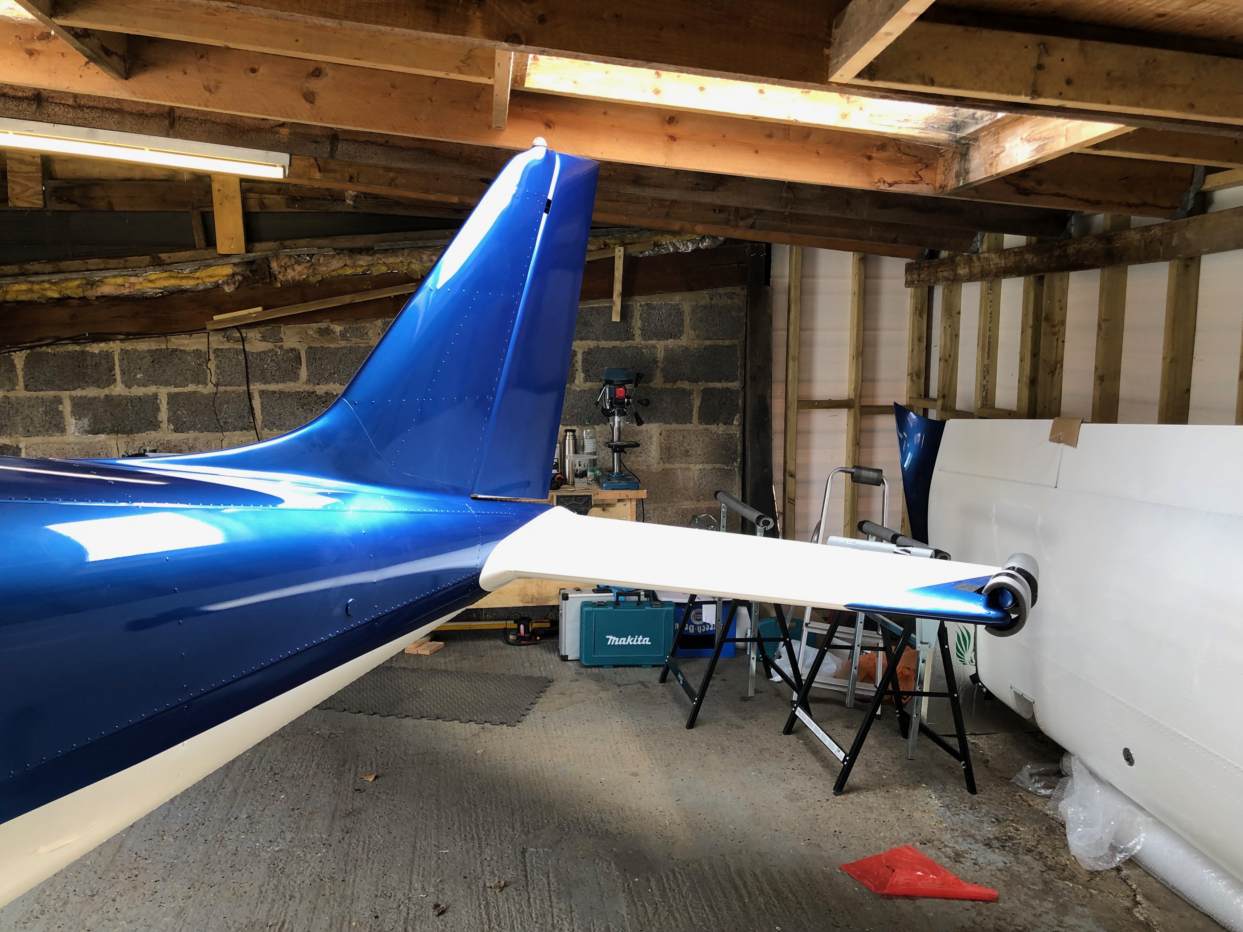
Amazingly more wiring today! Next on the list is the trim system. Once that’s complete I’ve arranged to get some help to fit the tailplane and then finishing off with making a start on wiring the ignition switch.

Most of the Dynon connectors consist of a loom of wires but they’re not normally terminated so require the pins to be crimped on with a 4 jaw crimping tool.
Partially populated but a lot more wires to add.
Fitting the tailplane requires 2 people. It locates on 2 pins that ensures the correct placement. All paint and debris needs to be removed and then greased before attempting to fit the tailplane No pictures of the process as it was quite tricky to fit.
Job done. The tailplane is secured by 4 bolts that are torqued and up before being wire locked.
Next a start on the magneto switch wiring. The two connectors have two holes that are wired and run to the ignition switch.
The wiring of there were very difficult and didn’t go to as I expected. The instructions give the impression that the pins can be slipped into the plug whilst they are still connected but this wasn’t the case. They needed to be separated first before the pins could be inserted. Took about an hour to sort this out.
The engine wiring is now complete and look quire neat.

Monday 24th June 2019

Music: Tears for Fear and ABC

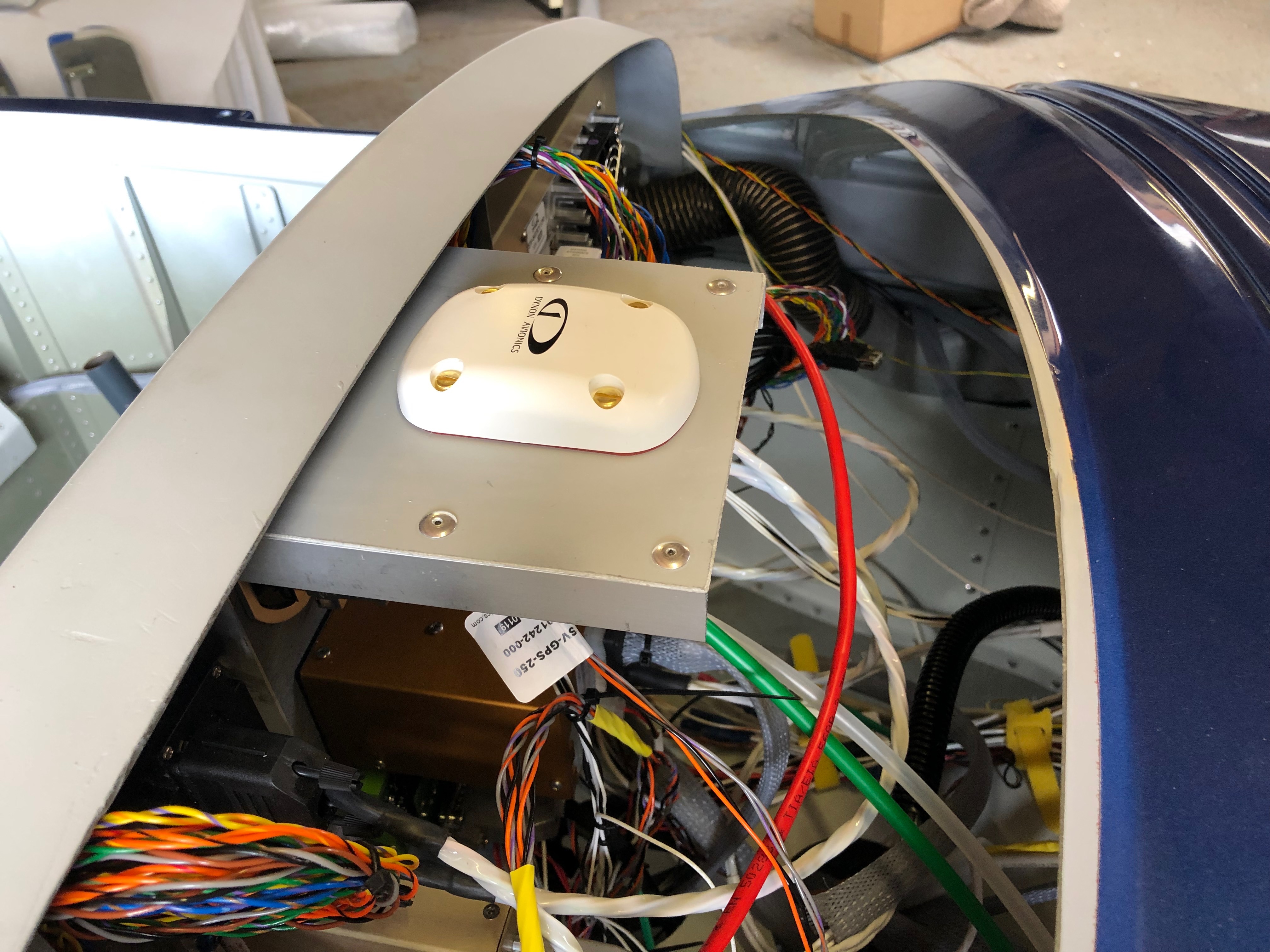
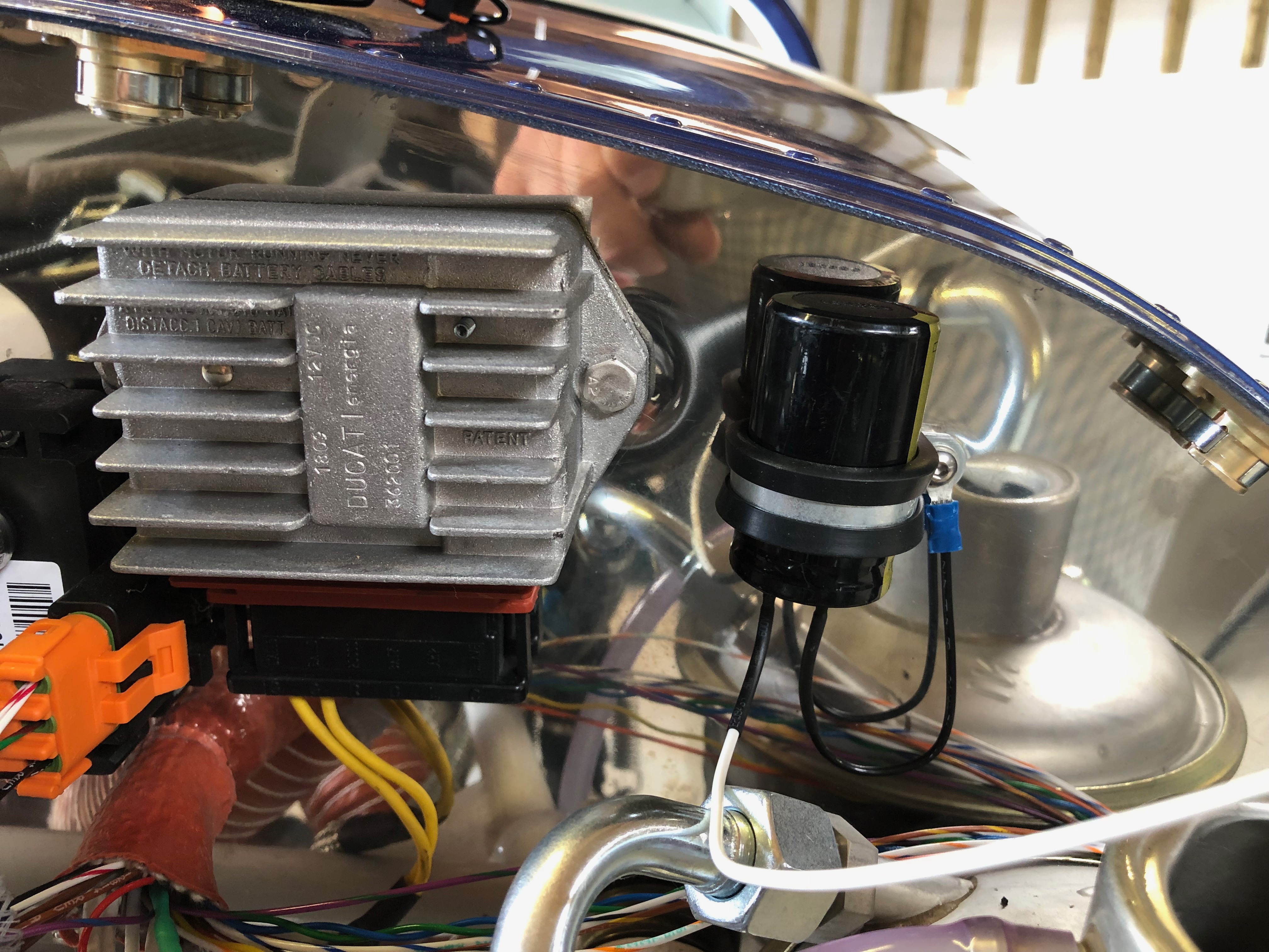
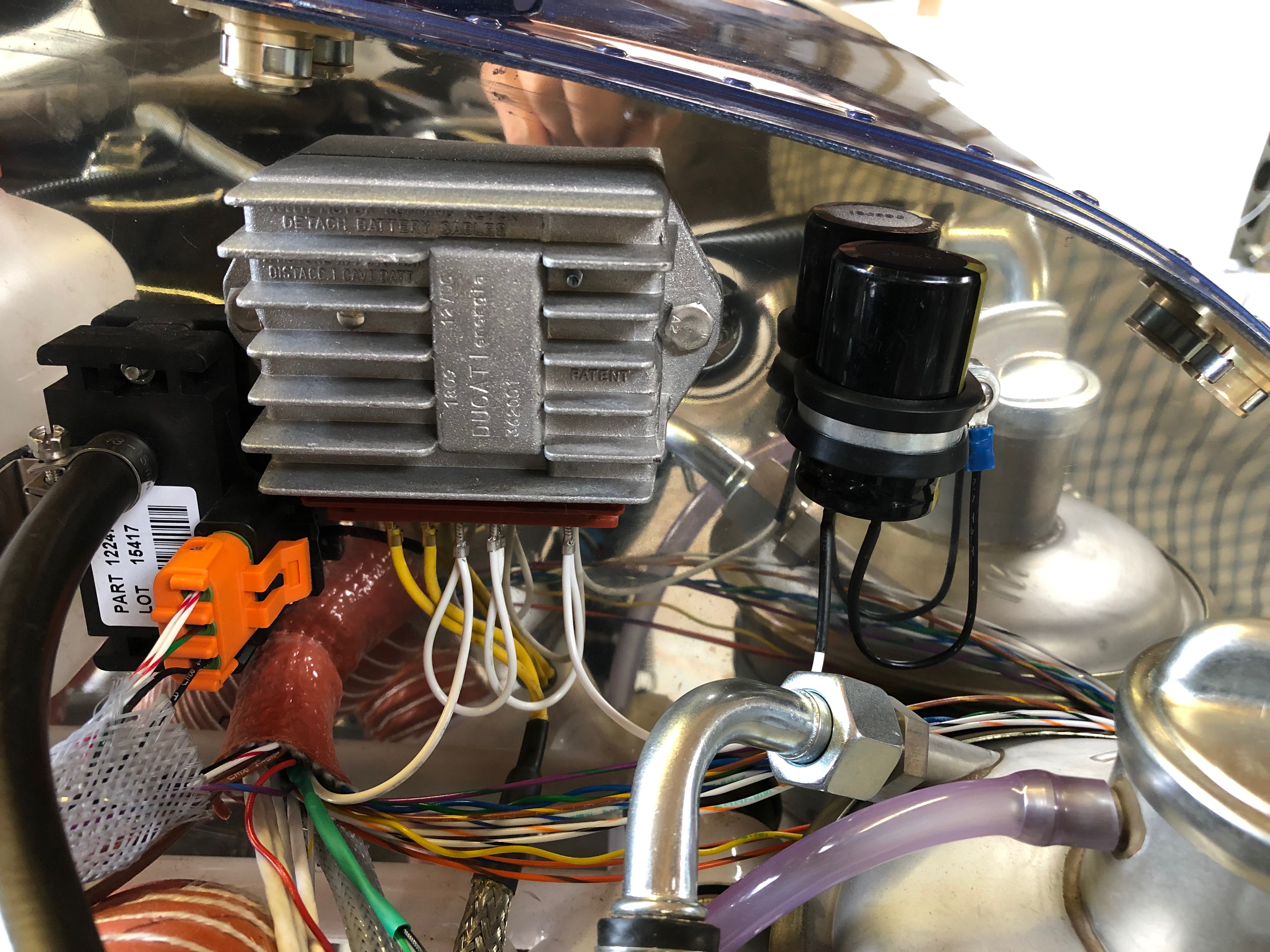
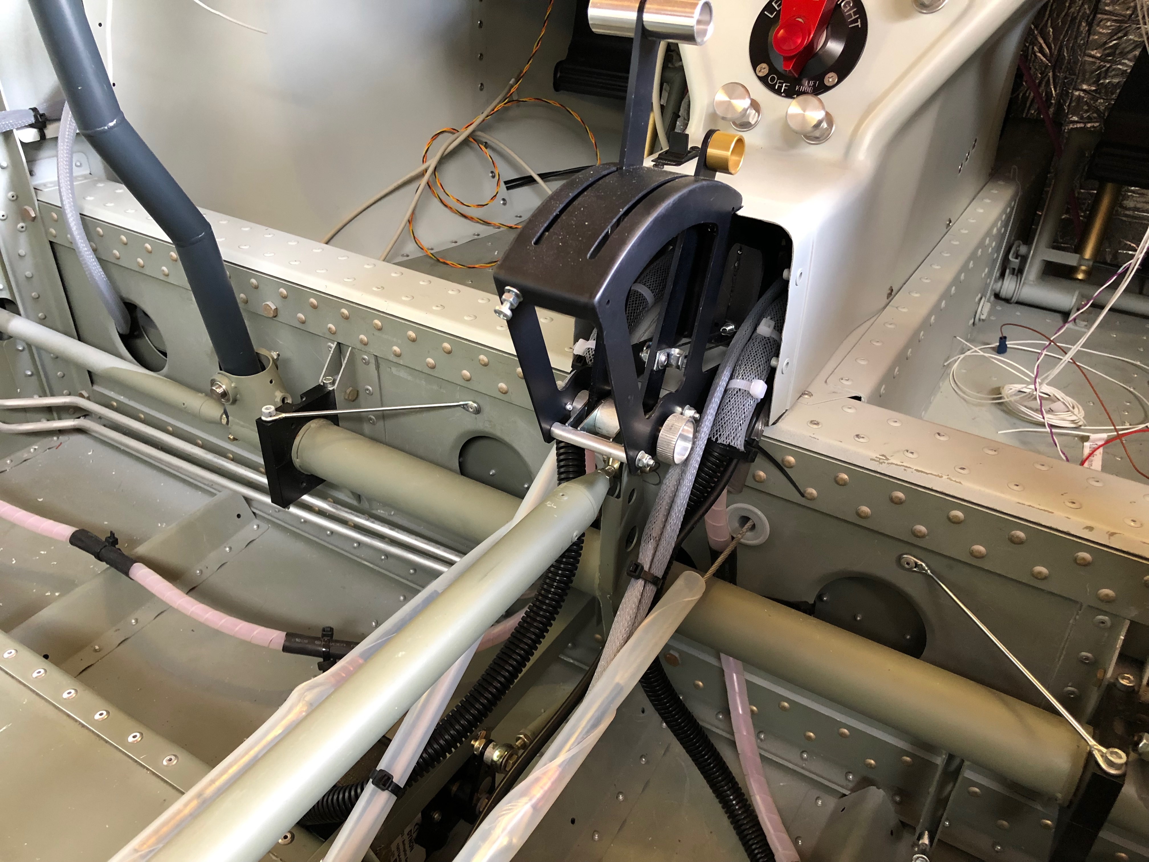
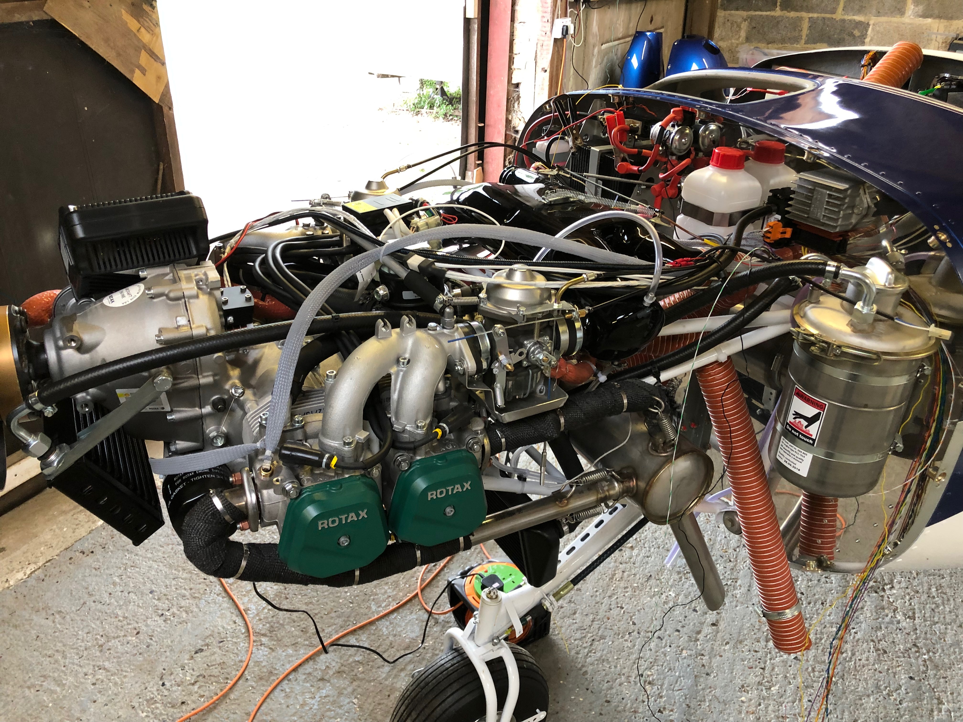
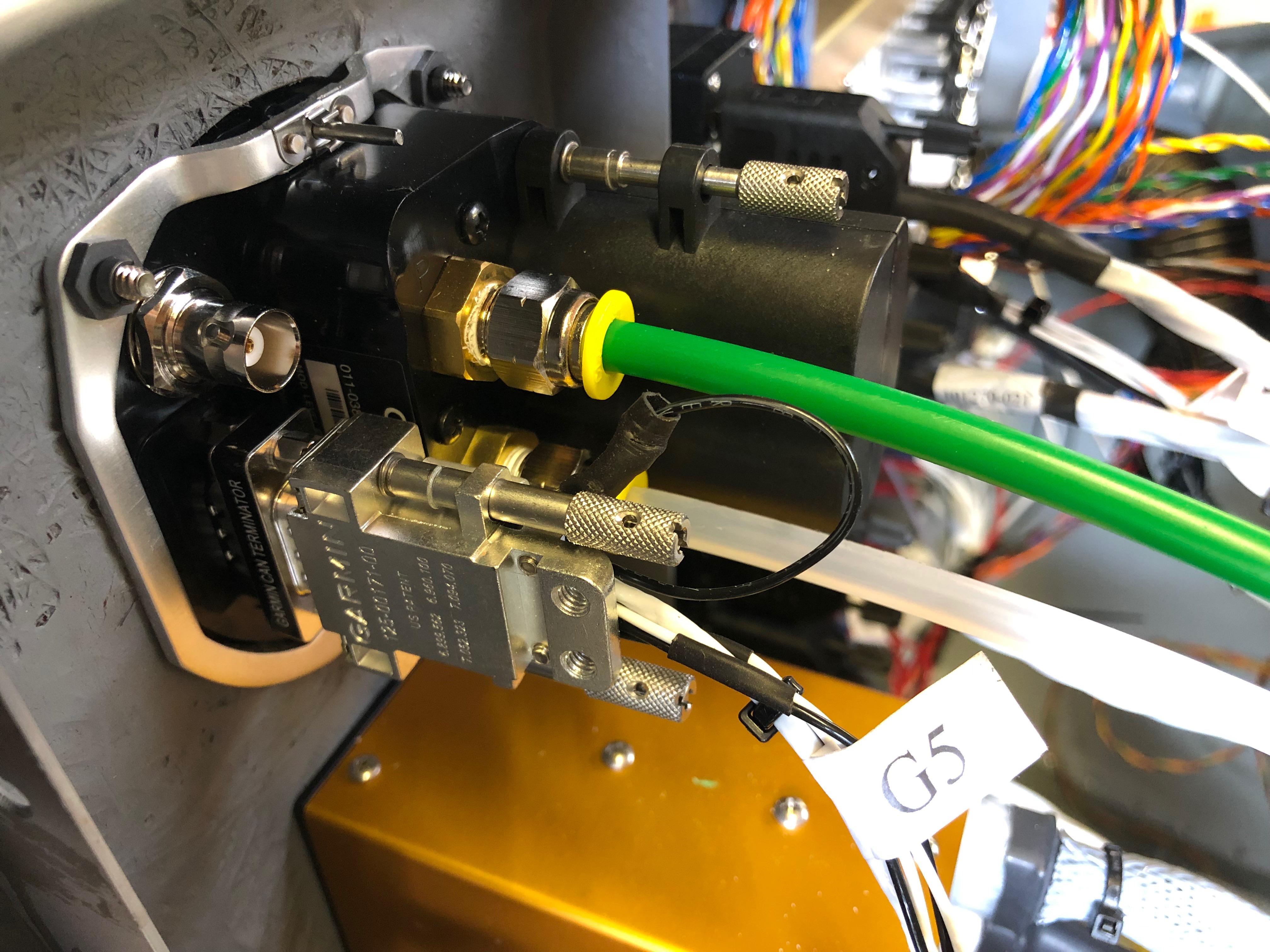
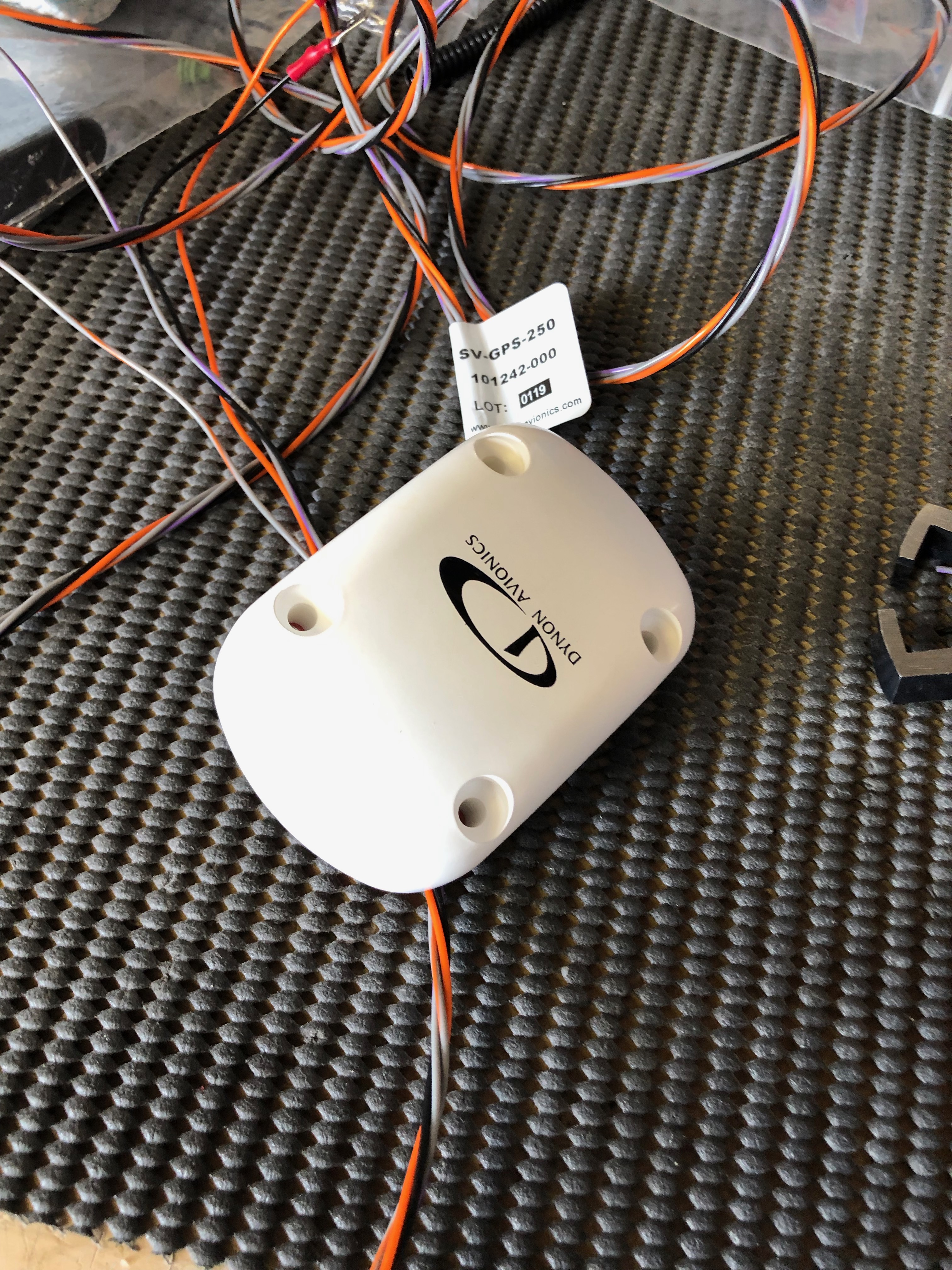
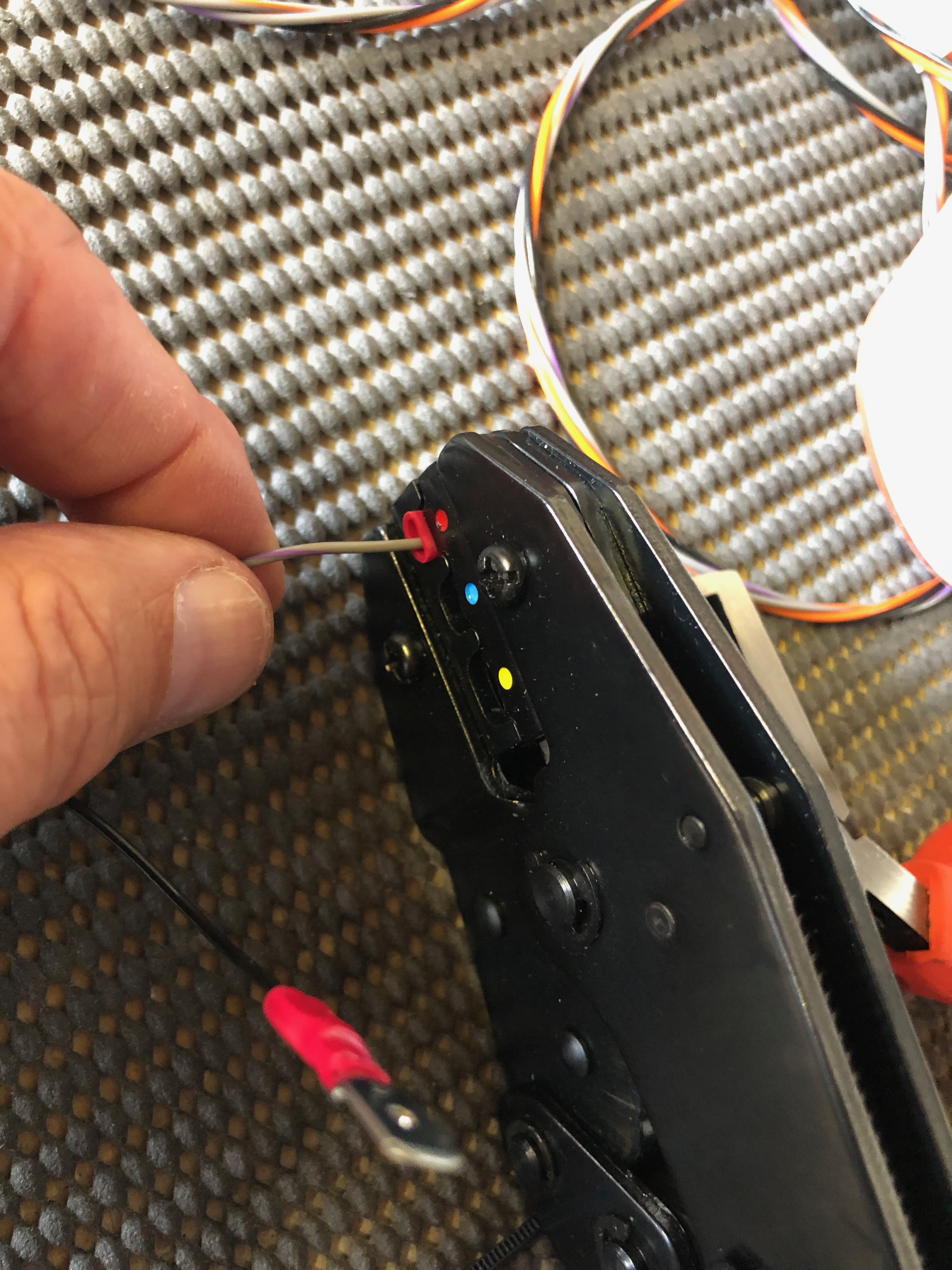
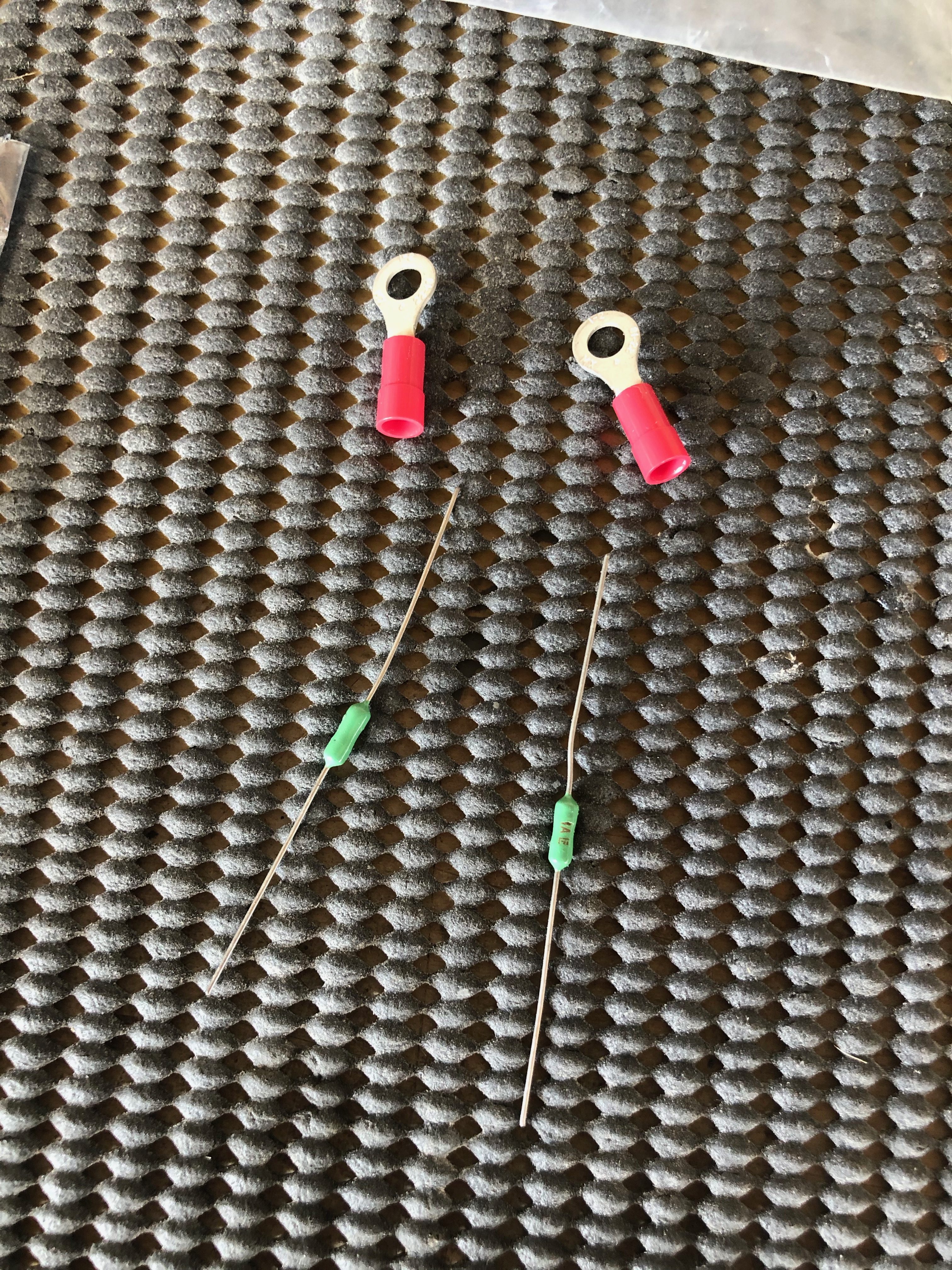
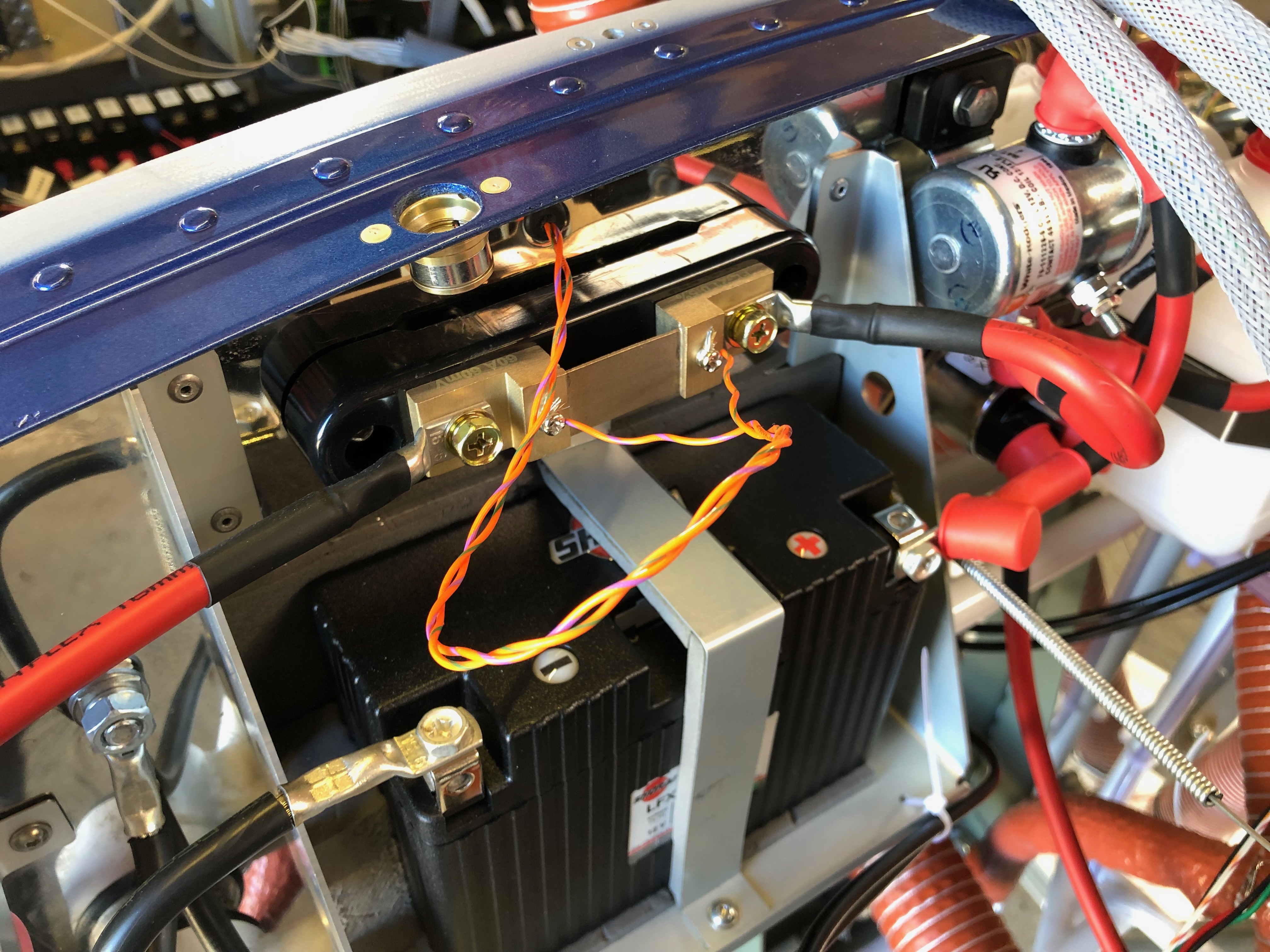
To give me a break from wiring I thought I’d start with a job that included some wiring after I finished it! Installing the GPS unit. Then back to wiring, first the charge circuit and then onto the the control sticks which includes the trim, radio and autopilot functions.

I decided to make a bracket out of some aluminium angle that could be fixed to the strengthening that I added to the rear of the panel.
After cutting 2 pieces 15 cm long I riveted a piece of the offcuts from the panel to use as a surface to mount the unit.
The mount works well but unfortunately there really isn’t any other place for the GPS so it will sit on this mount under the glare shield.
Next up is installing the wiring for the charge circuit. It requires a large capacitor that smoothes the output and protects the regulator unit from overcorrect spikes..
The completed charge circuit. It’s simpler then circuit diagrams make out.
I decided to get new Ray Allen control stick grips which are an enhancement on those supplied with the kit. They have 7 buttons instead of 5. The stick wiring requires 8 wires to be run down the control stick and onto various contacts. 4 are for the trim up, down, left and right, 1 is for ground, 1 for PTT and the other two are for whatever you want to use them for. I’ve decided to use one for autopilot disconnect and the other for the autopilot ‘Level’ function.

Friday 21st June 2019

Music: Fleetwood Mac and The Pretenders

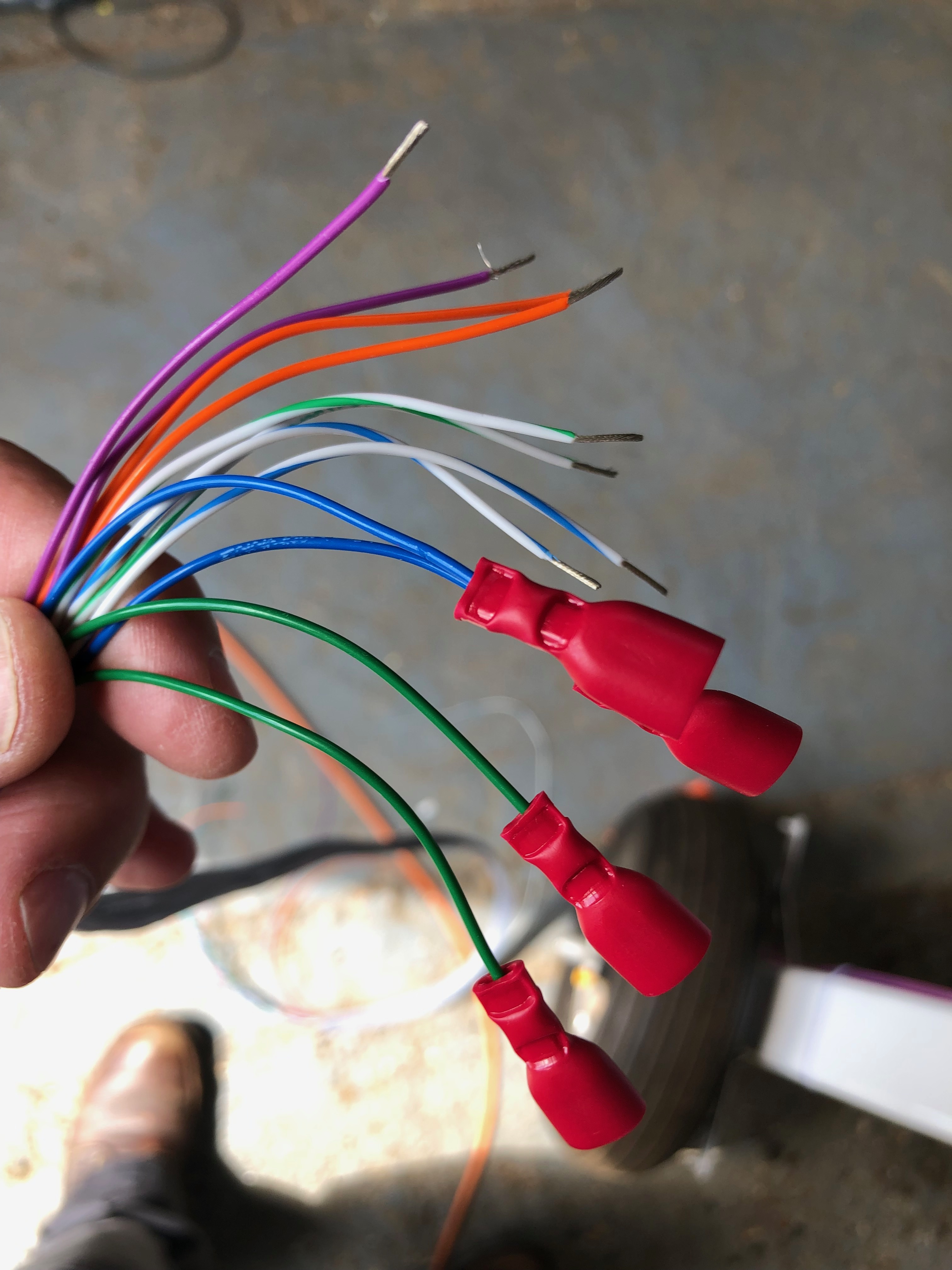
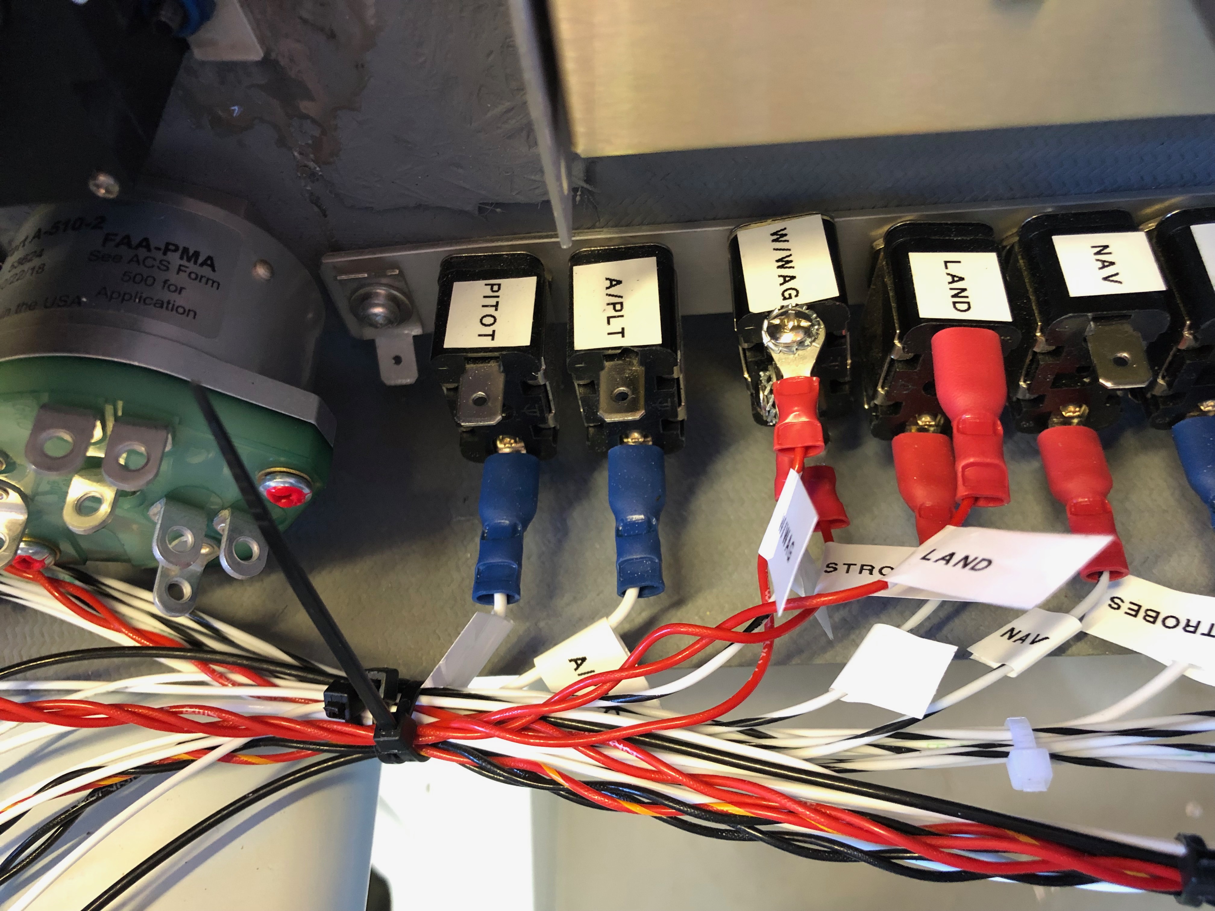
Wiring continues! Most of the time it takes is making sure that the routing will work for the circuits concerned, keeping it tidy and labelling the wires. Hopefully I’ll be finishing the landing lights, nav lights and pitot circuits if my delivery of wire arrives today. but most of its done now.

The documentation that came with the Rotax engines didn’t have the information on the soft start module. Luckily I’ve found some information on a web site that gives me the information that I needed. Unfortunately I haven’t received the wire that I’d ordered so I diverted on other tasks.I
I’ve had a proactive day, completing all the tasks that I’d set myself. The lack of photos is because there’s only so many pictures of wires you can take!
The power and ground distribution units are filling up nicely!
and all the switches apart from the Alternator switch have been wire. Work resumes on Monday after a day instructing tomorrow and a rest day Sunday!

Thursday 20th June 2019

Music: Gerry Rafferty and Daily Mix.

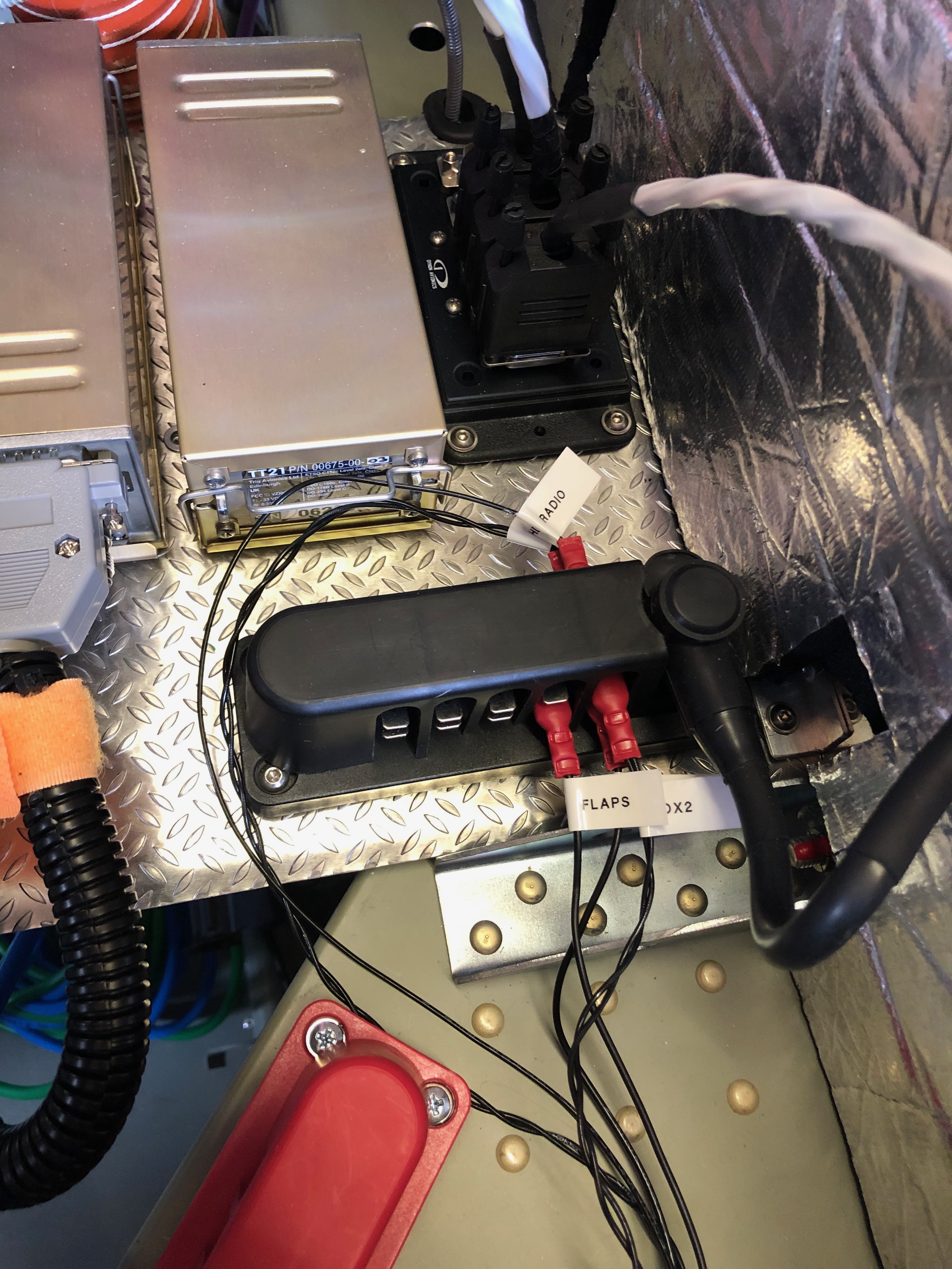
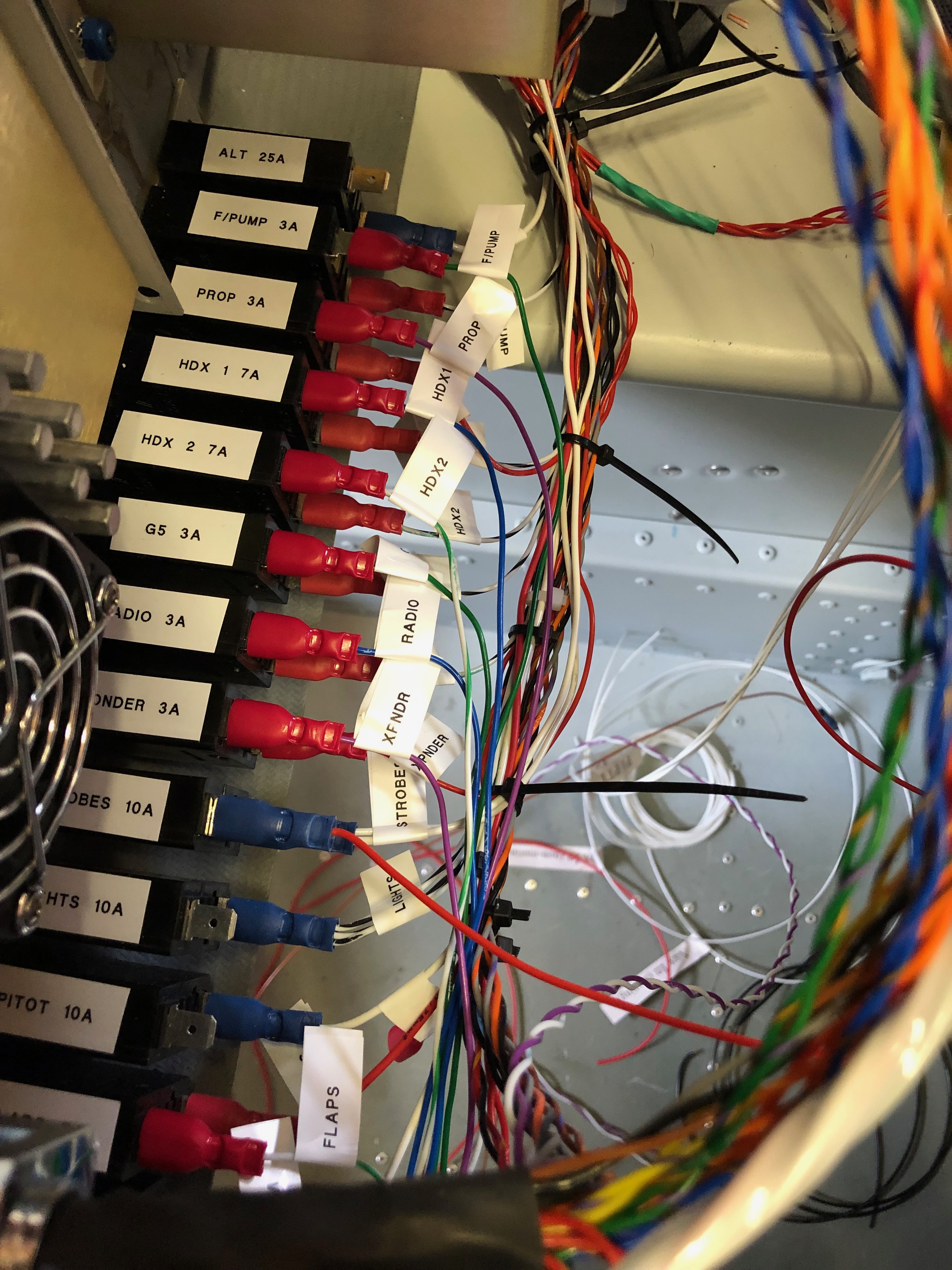
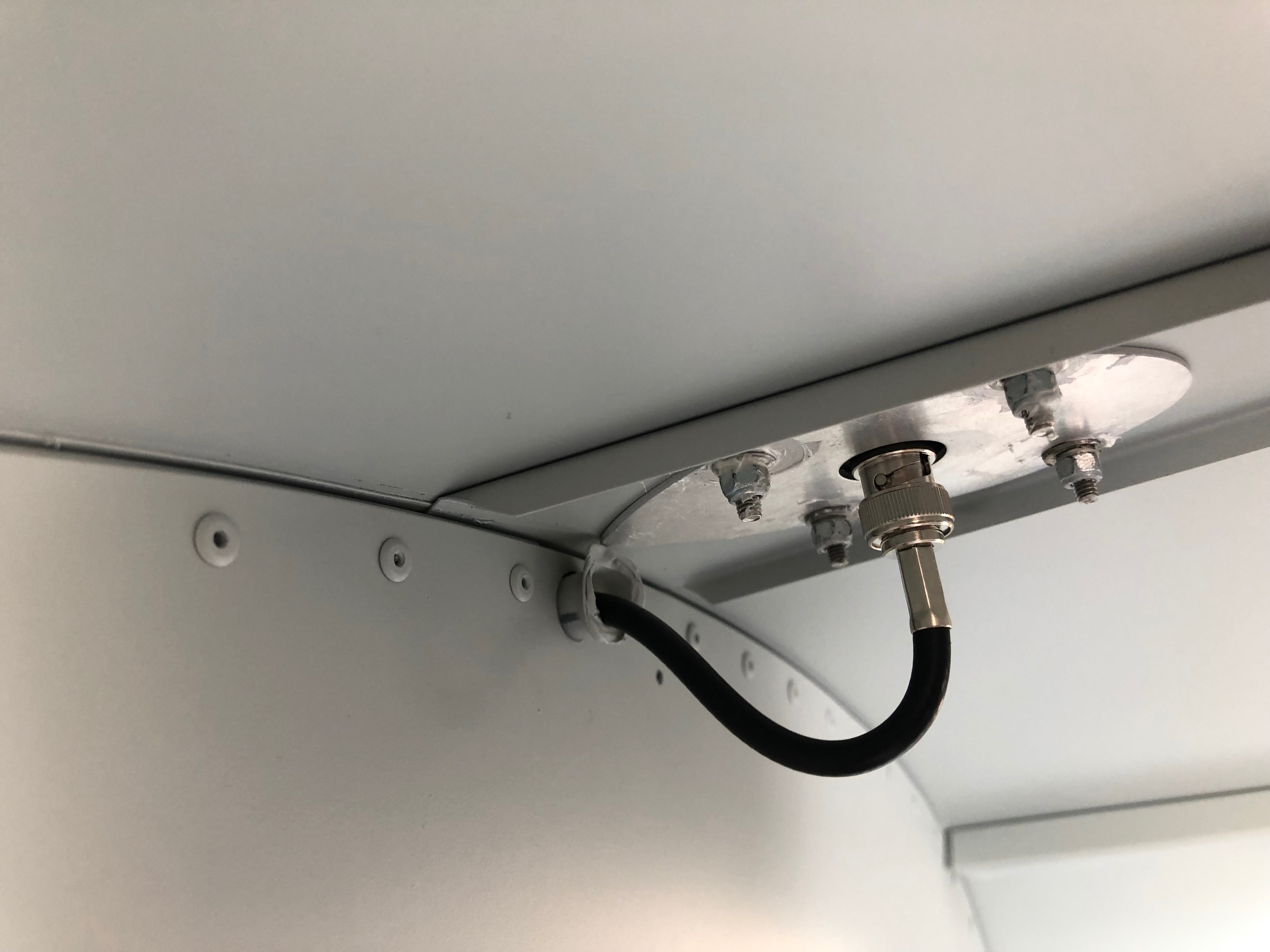
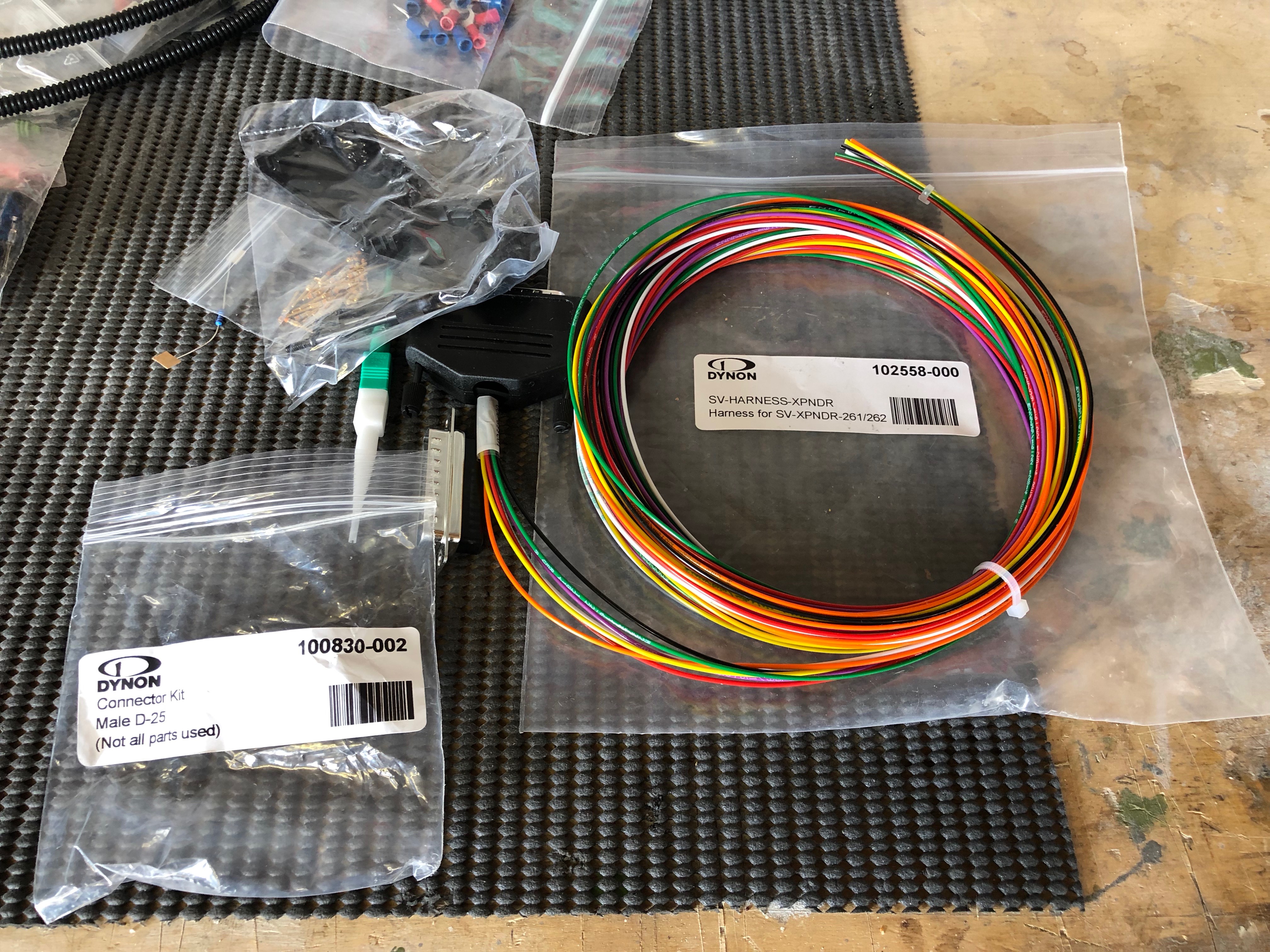
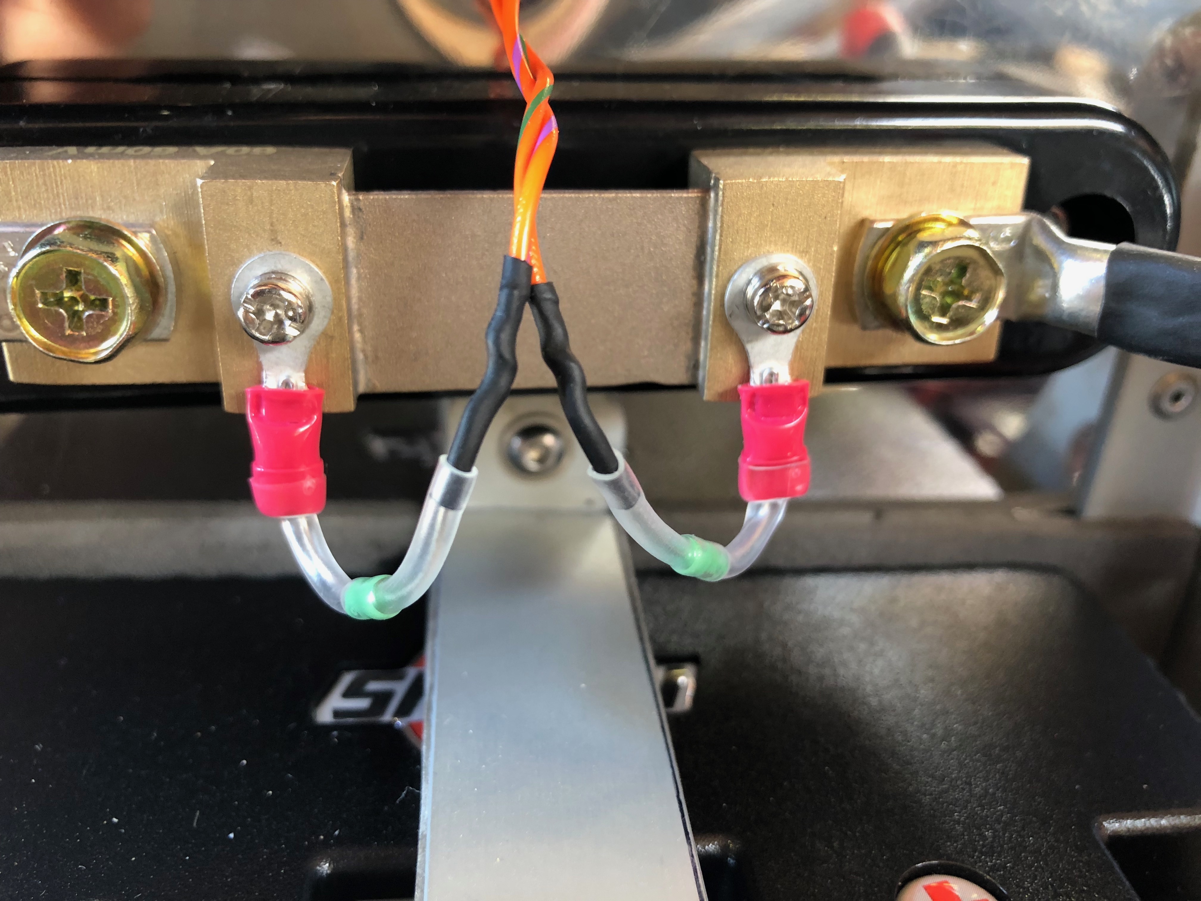
A lot to do today, as every day! When the delivery arrived I found that some of what I had ordered was out of stock. It’s not a big problem as there are lots of other jobs to do. So I’ll wire up the power side of the system and label, install and test the radio and transponder coax cable.

Time to wire up the power side of the electrical system. I’m reusing the wire that I have leftover from the other circuit wires that were trimmed back. There’s plenty to do the job although not a unified colour as long as they are labelled it will be ok.
My new friend. A Dymo Label Manager 200 that I bought some years ago. It’s been invaluable and luckily I managed to get some label cartridges.
The +ve bus with 11 of the circuits completed.
The circuit breakers connected, some tidying will be required but it’s mostly complete.
The complete panel powered up for the first time. The system shows a 7 amp power drain which is roughly what I had calculated.
My DPD delivery was a day late but got delivered at 10am so I could get on with the wiring of the Transponder and Radio with the coax.
The radio coax cable runs through conduit in the fuselage and is terminated with a TNC connector that I’ll do tomorrow.
With all the cables protected with sleeving or conduit and secured in place I can fit the interior trim.
The rear of the cabin. I’ve checked the radio/headset loom and it works fine so I need to mount the LEMO headset connectors and then I can fix the interior panels.
Right side of engine. All the sensors are connected except the Tachometer, soft start module, magneto wires.
Left side of engine.
Looks a bit busy but with a bit od tidying it will look a bit neater. Quite pleased with the progress so far.

Wednesday 19th June 2019

Music: Spotify Daily mix

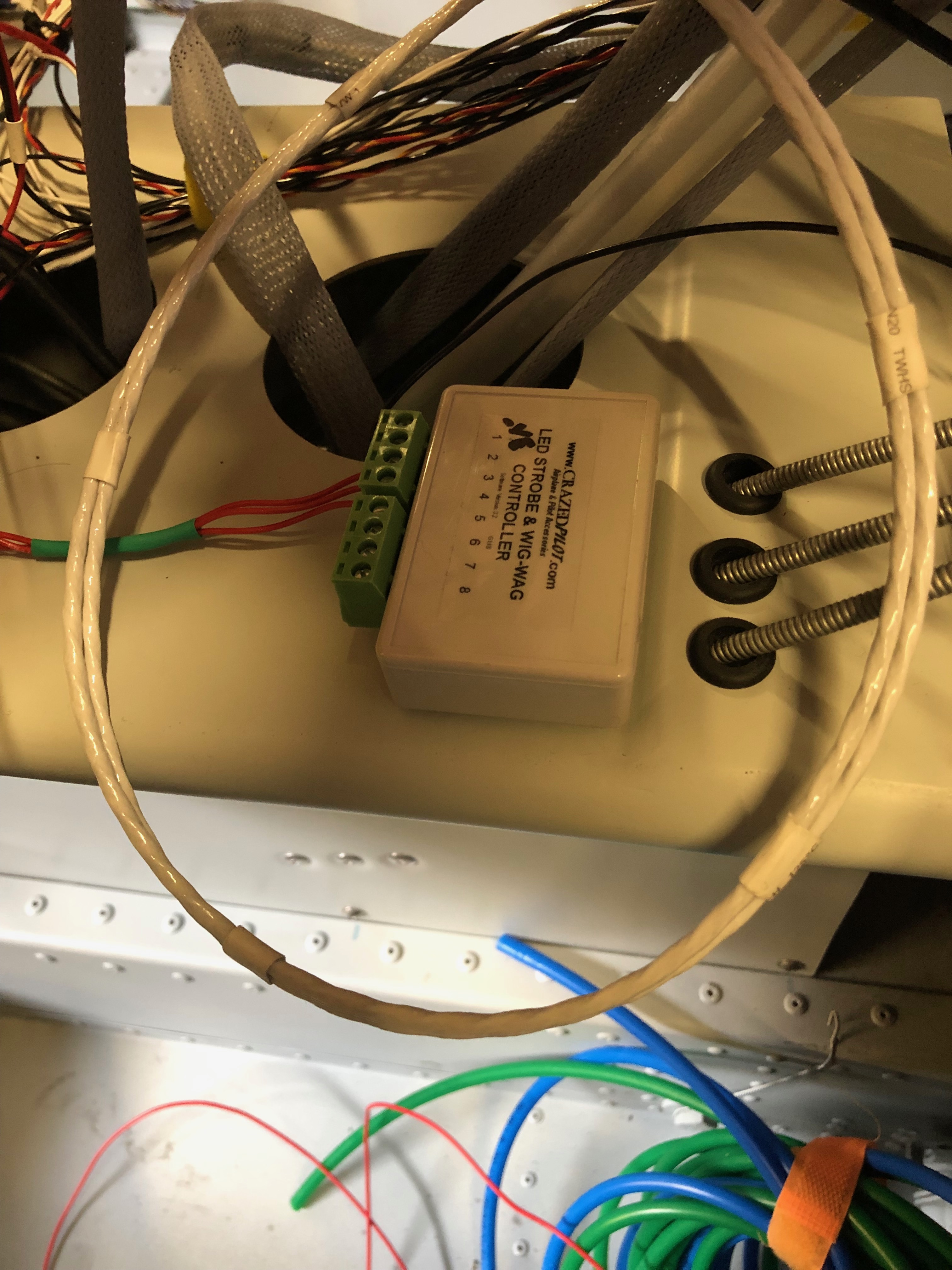
The wiring continues today with a couple of other items that I had put on the back burner. The tail strobe circuit was completed and wing strobe wiring started. One being the wiring of the extension wire for the elevator trim and the other the pressure plumbing for the G5.

After shimming the ADAHRS unit last night I replumbed the pressure system to make it tidier…
…allowing me complete the plumbing to the G5.
I thought I’d start on the trim motor wiring but unfortunately DPD failed to deliver the wire I’d ordered so will do that another day!
One of the jobs that I had been diverted from was the wiring up of the elevator trim so first thing is to solder them together and make sure that the colours match what I did for the aileron trim motor.

Tuesday 18th June 2019

Music: The Pretenders – They were the support to Fleetwood Mac on Sunday at Wembley. I’d forgotten how good their music was!

Time for a short break from wiring but not for long before continuing the battle of the wires!

The Rotax engine comes with 4 litres of Aeroshell oil which I thought I’d add to the oil tank as a short break from wiring!
I managed to get 3 litres in the tank but I will need to add more when the engine has been turned over a bit as there are a lot of empty oil pipes at the moment!
After that very short break it’s back to wiring. This is the transponder loom which is a bit overkill for my needs.
As you can see by the coil of wire there is a lot of unused wires but and a lot more has been trimmed from the length of the wires that are used! Once I had checked that it worked as expected I cut the unused wire off and covered the unterminated ends with heat shrink.
Before adding a GPS receiver the SkyViews have no idea where they are in the UK, in fact they think they are in the USA! So I’ve taken the power and serial data leads from both SkyViews, spliced them and will connect them to the GPS.
There’s a lot of cutting of wires and terminating them, mostly with fully insulated spade connectors using a special crimping tool.
Once the GPS is connected a check is made on the connection to make sure it’s not reporting any errors and picking up satellite receivers ok..
…and if by magic the SkyView now knows it’s in the UK! The system is reporting height and position correctly from my checks. If you look at the slip indicator you can see that its not in the middle and that’s because the ADAHRS isn’t quite level. There isn’t an adjustment that can be made to correct this so I’ll shim the unit.
I’ve positioned the aircraft on a piece of level ground and I’ve shimmed the unit to make sure that it’s level and reporting correctly which it now is.

Monday 17th June 2019

Music: Fleetwood Mac – Saw them in concert at Wembley last night. A little treat from Karen – Absolutely fantastic!

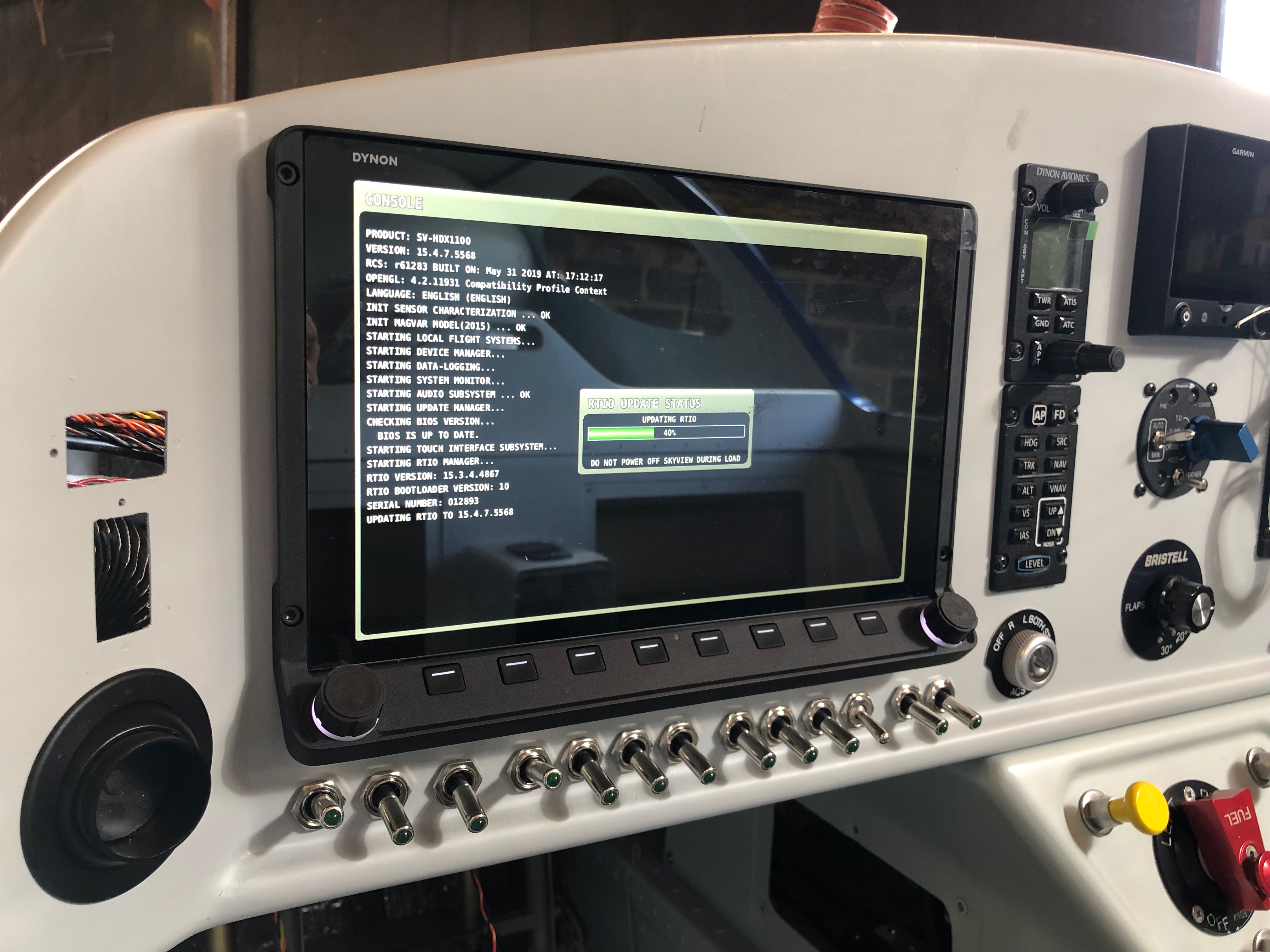
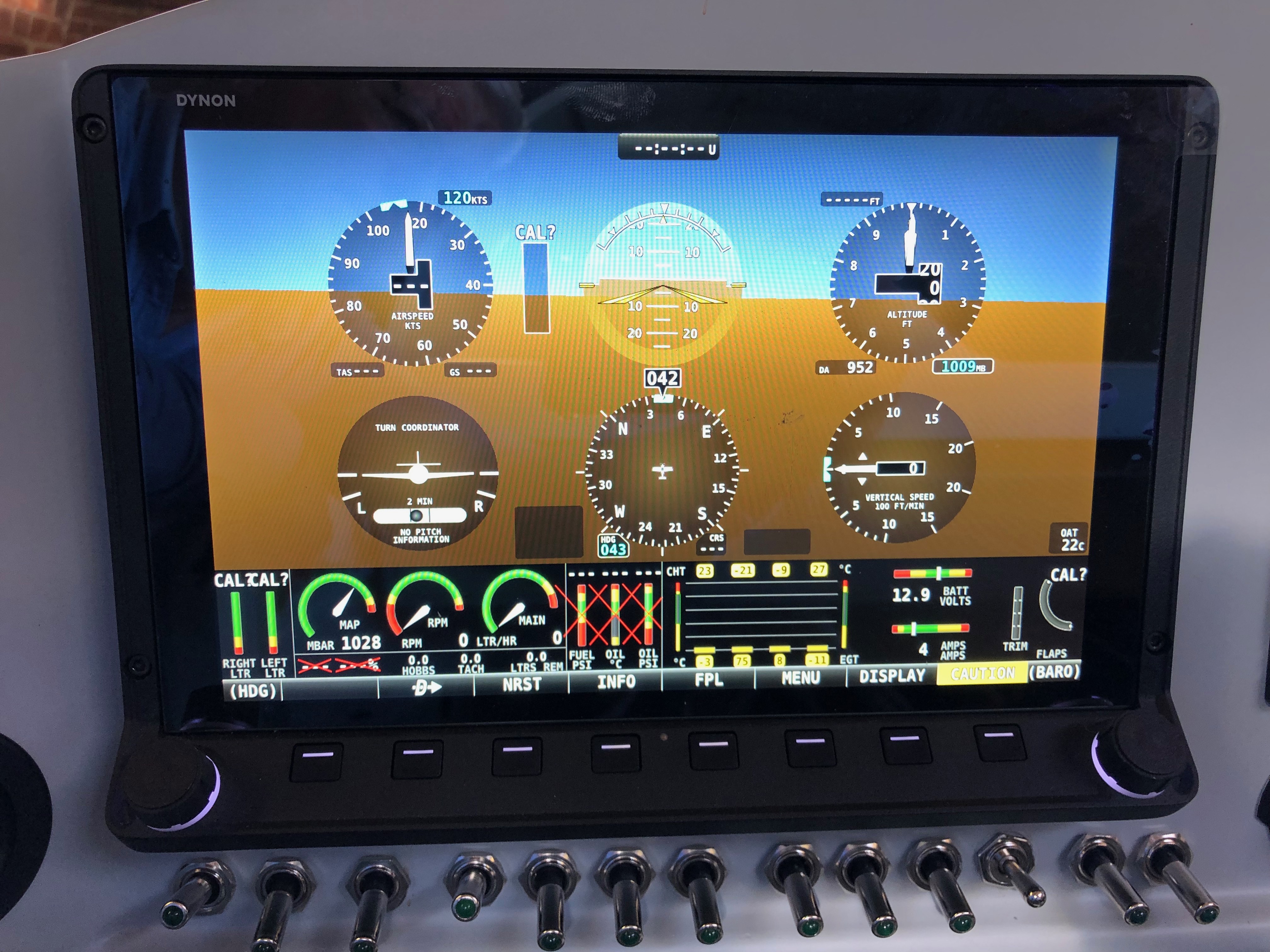
The wiring continues, after each circuit is wired up a check to see if it’s working as expected. All good so far!

As mentioned previously I need to protect the SkyView from a surge from the Amp Shunt so I’ve purchased some 1 amp inline fuses. They are very small…

… and make for a very neat protection solution when positioned inline.
With all the wires ‘under the bonnet’ it’s difficult to make it all tidy…
…but I layout all wire first to see where best to route them before trimming to correct length and terminating. All these will need to be secured too with stand-offs as required.
The servo looms are next. I’ve installed the looms as far as the cockpit and now need to terminate each wire and make up the connector. It requires crimping the pins on each wire with a 4 way crimper.
After crimping they are inserted into the D9 block…
…and the backshell is added. Fairly straightforward but you have to make sure that the crimps are secure. There are two of these, one for roll and one for pitch. Once made up they are plugged onto the SkyView network hub.
Next up is to finish off the engine sensor connections. The correct pinout from the D37 connector is identified and the wire routed as described before trimming to the correct length and terminating. In this case a uninsulated spade connector that slips over the sensor connector. This is the LH CHT sensor…
…and the oil temperature sensor.
A quick check that everything is working. The CHTs, EGTs, Oil Temp, Fuel pressure, Oil pressure, Voltmeter, Ammeter and autopilot have now been completed and work as expected.

Friday 14th June 2019

Music: Take That

I decided to visit Air Expo at Booker yesterday but I can honestly say the show was a complete waste of my time. It was raining all day and a lot of the exhibitors had scaled down their stalls and some hadn’t turned up at all! I did buy a Sky Echo II there so I’ll see how that works when I finally get the plane flying.

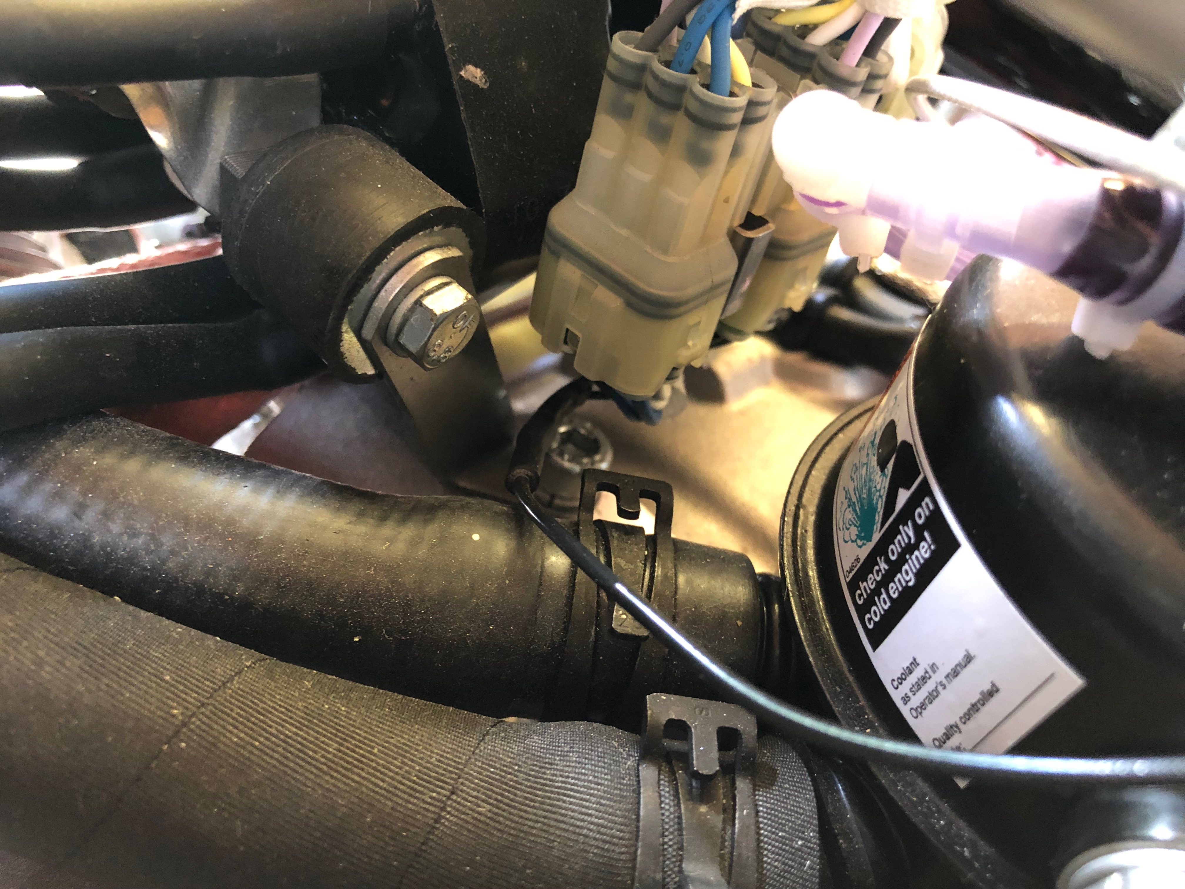
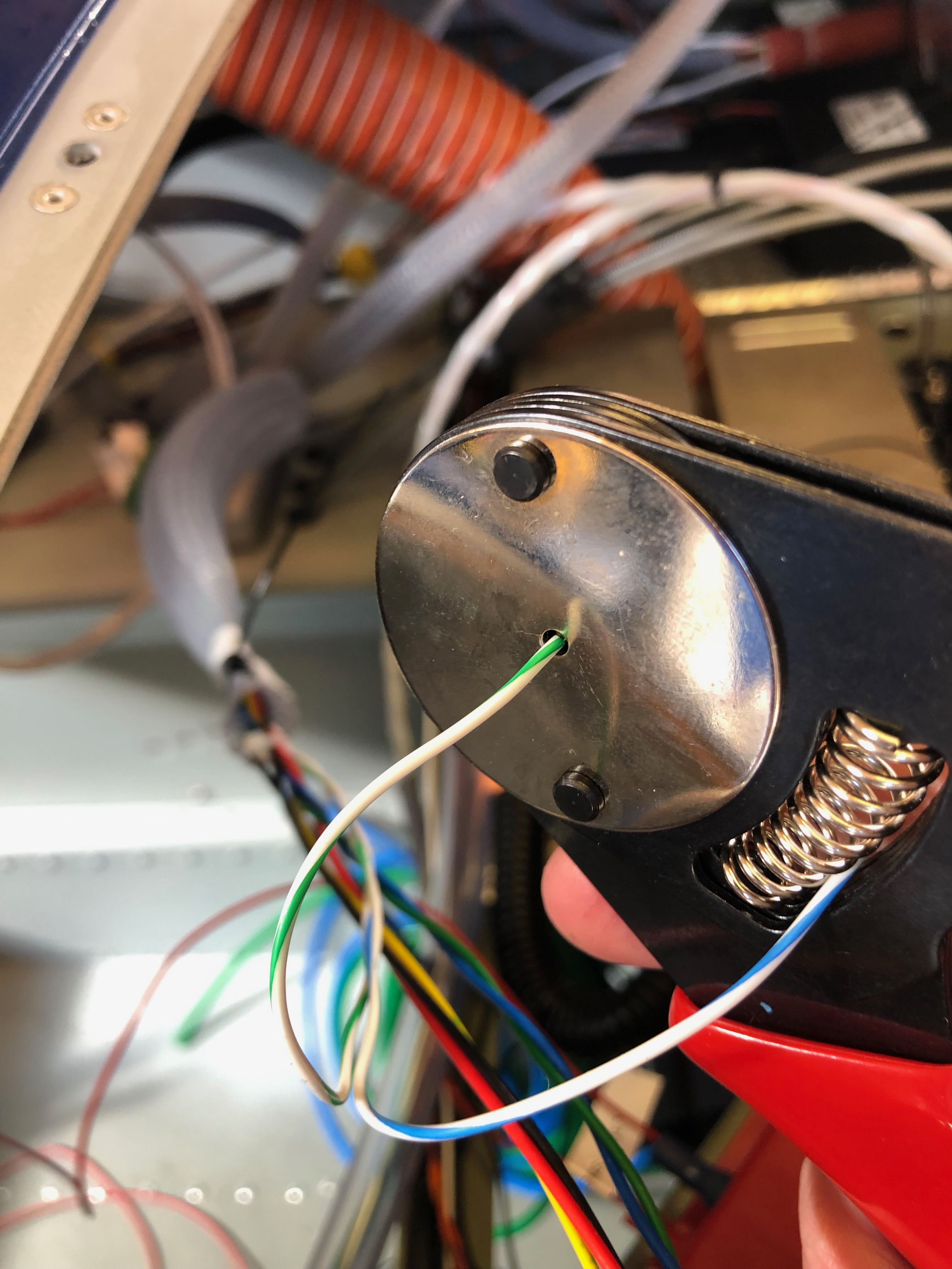
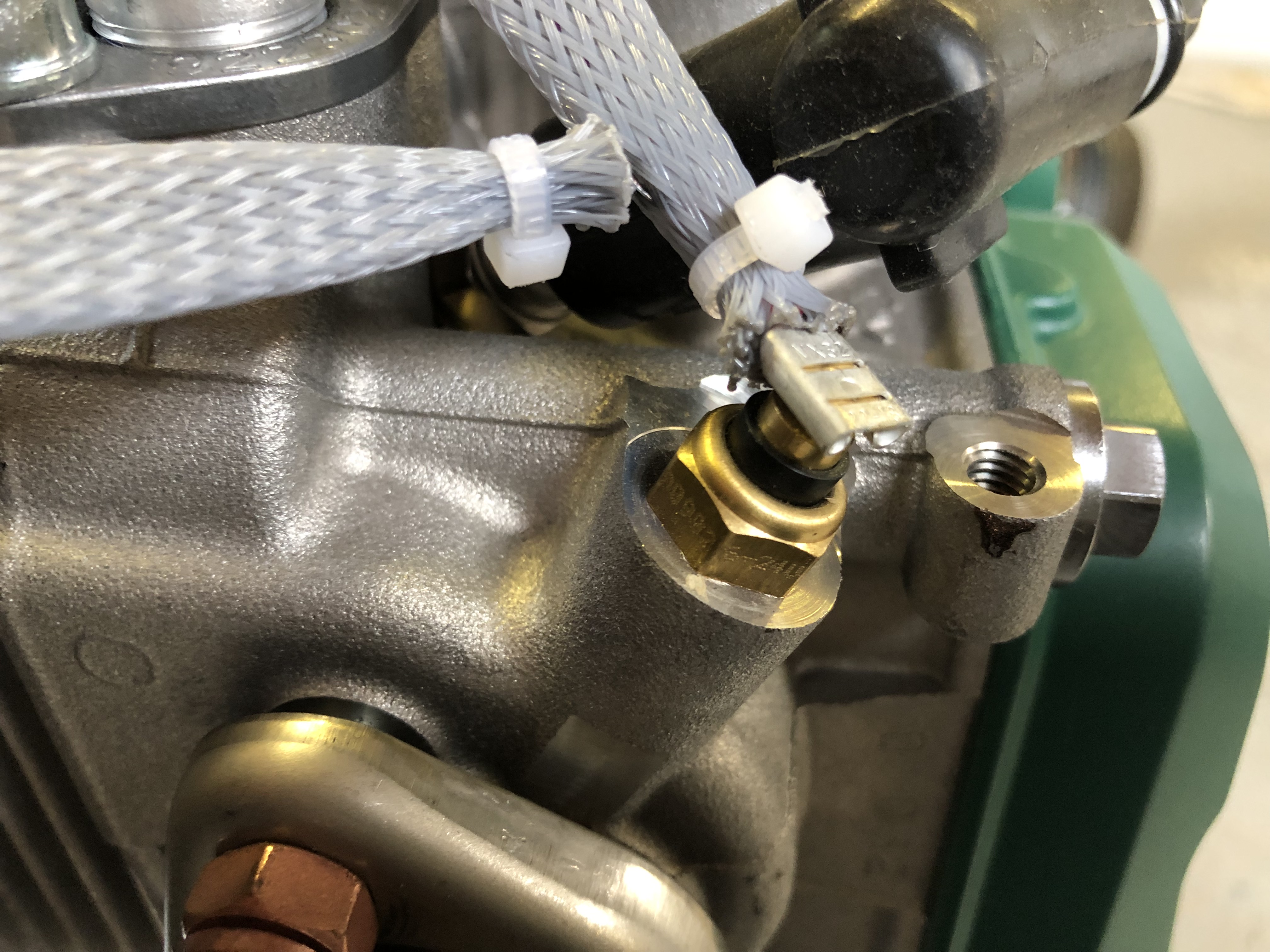
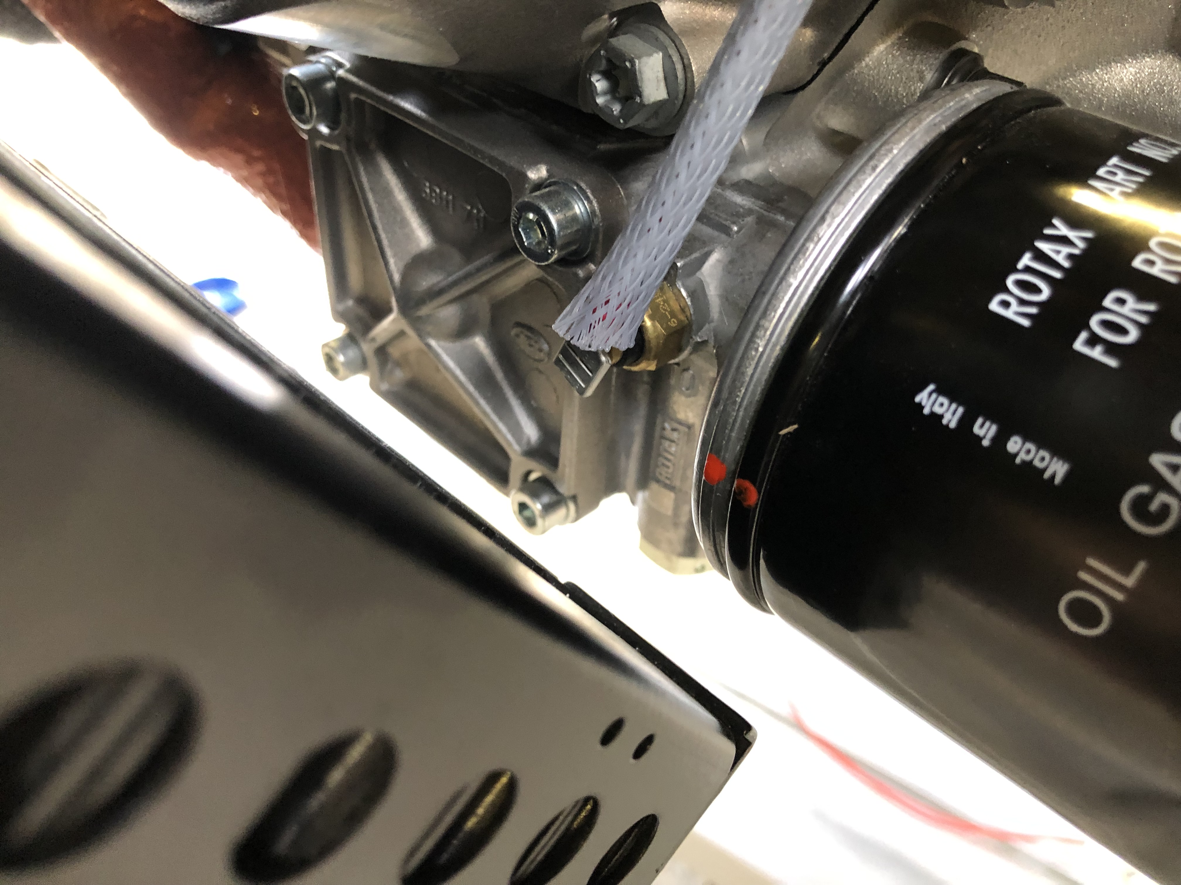
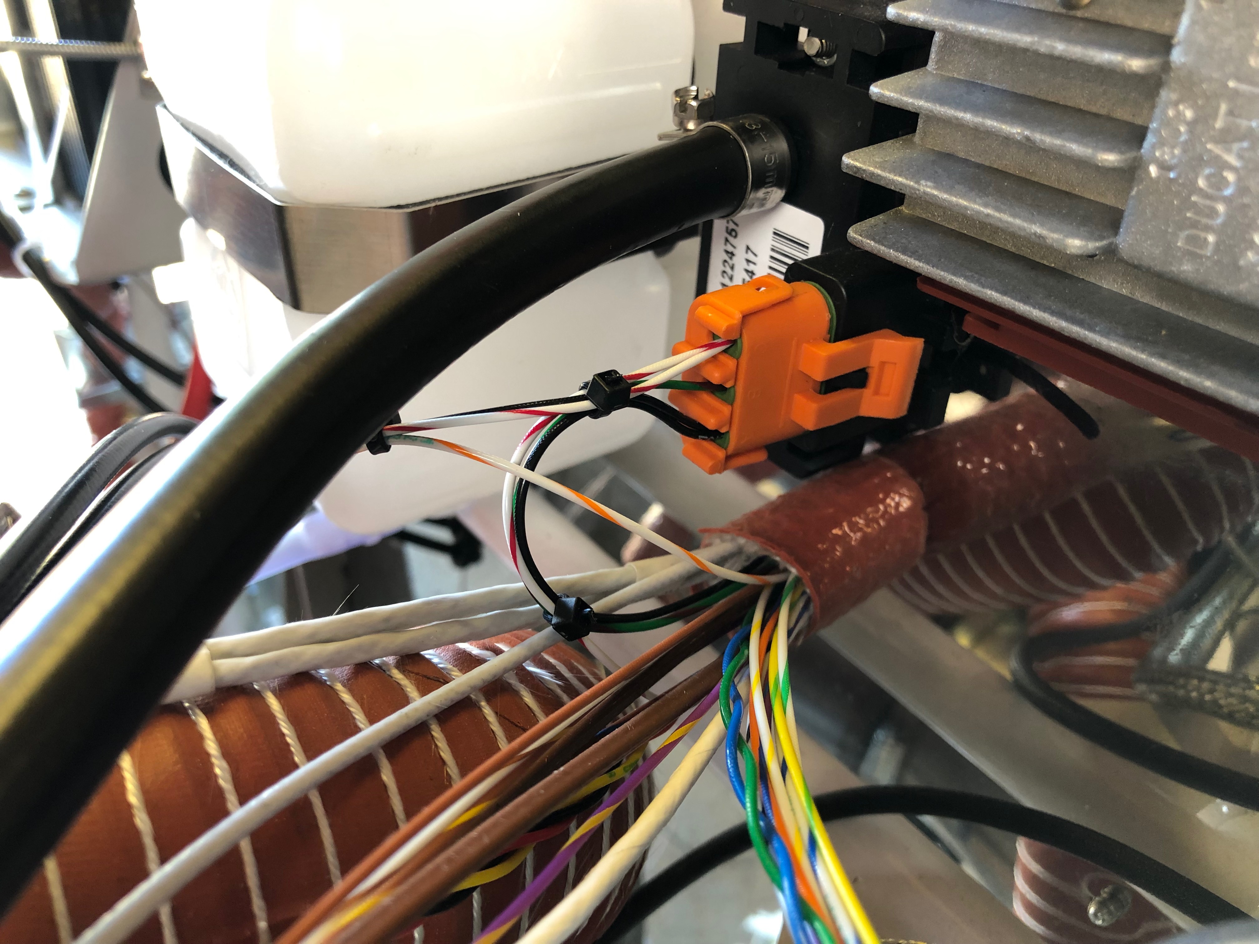
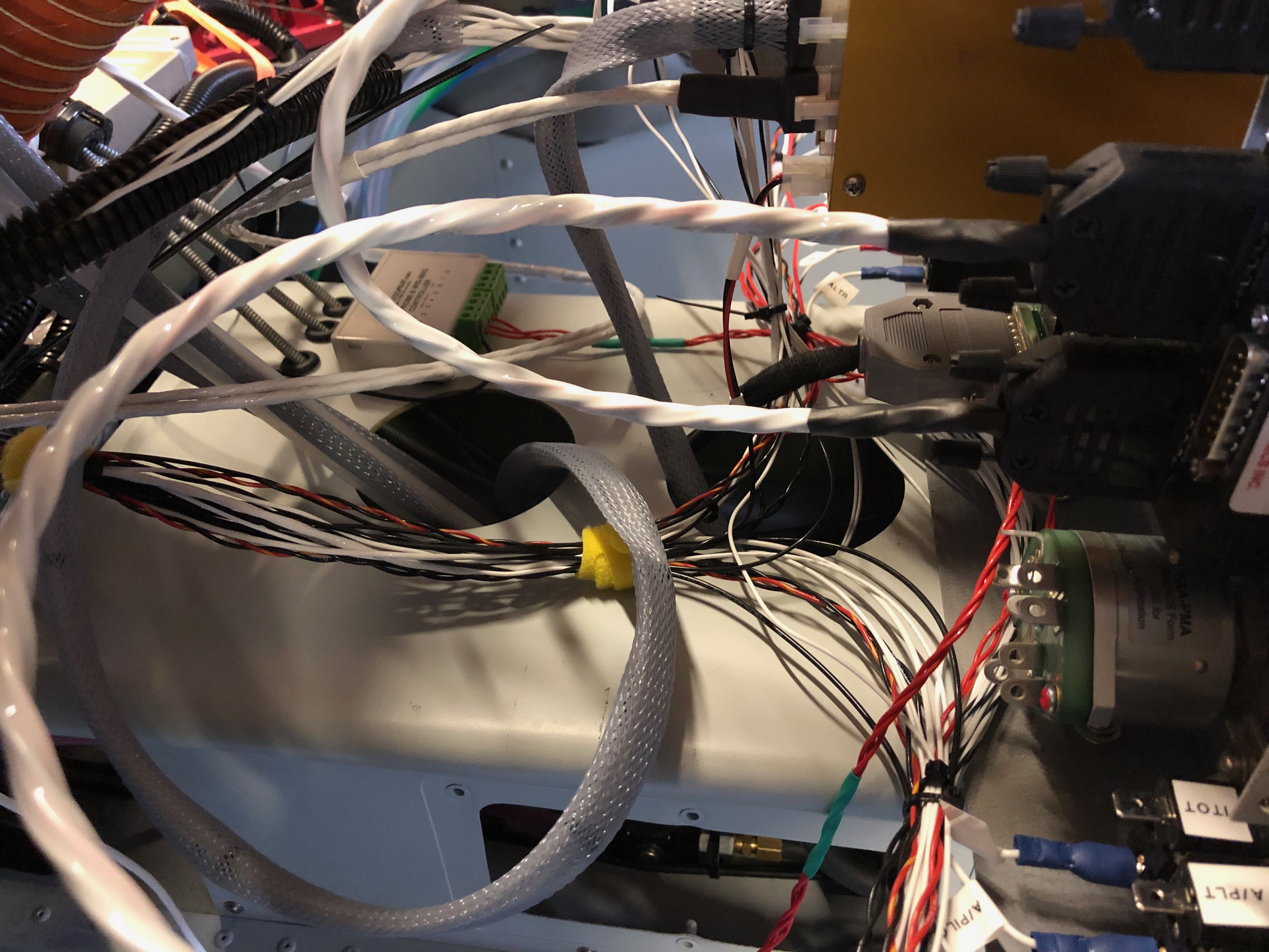
The aim for today was to continue the wiring and connect a few of the sensors.

The EMS loom has a D37 that connects to all the various sensors around the aircraft. It’s good to check the pin out with a multimeter before connecting to any of the sensors.
First up is the MAP sensor. The power and ground on this sensor can be shared with other sensors so I’ve broken out those pins to use for the the fuel pressure sensor.
The system power load can be displayed on the SkyView by measuring the potential difference across a precise resistive load, in this case a Amp shunt. The wires connect to either side of the resister. To protect the SkyView from high currents a 1 amp fuse is connected inline which I’ve ordered and will be arriving Sunday so I’ll fit on Monday.
The landing light controller that I bought from the States is wired up to a 3 position switch. I’ve designed the lights to be steady, wig wag and strobe. Hopefully it’ll work as designed.
To get the light functions I need a 3 pole and 2 pole switch.
The fuel pressure sensor is next but will be done on Monday now as I’ve run out of time.
The HDX displaying in s ‘6 pack’ mode but you can see some of the sensors working correctly including the MAP, voltmeter and ammeter readings.

Wednesday 12th June 2019

Music: Ed Sheeran and Turin Brakes

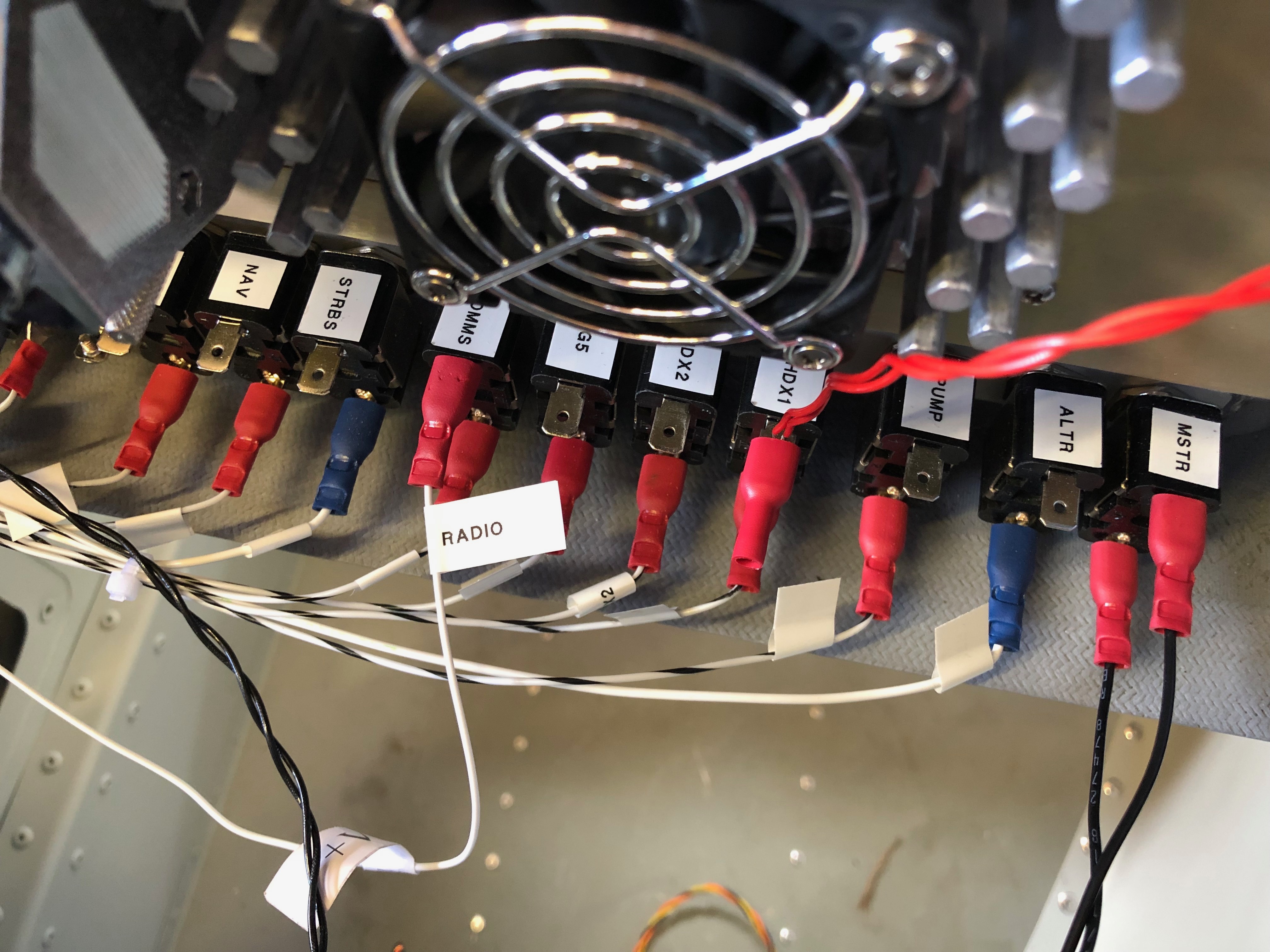
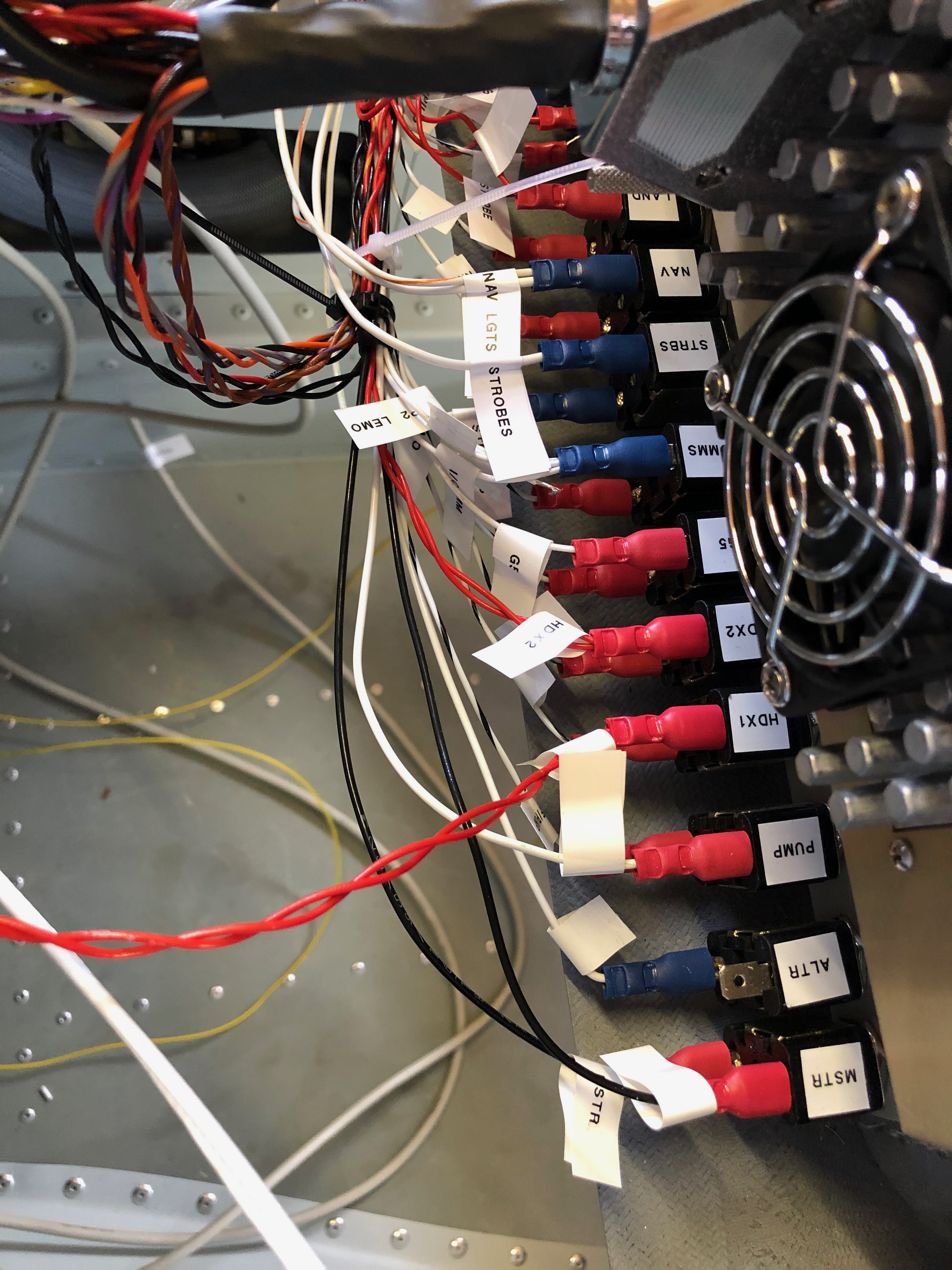
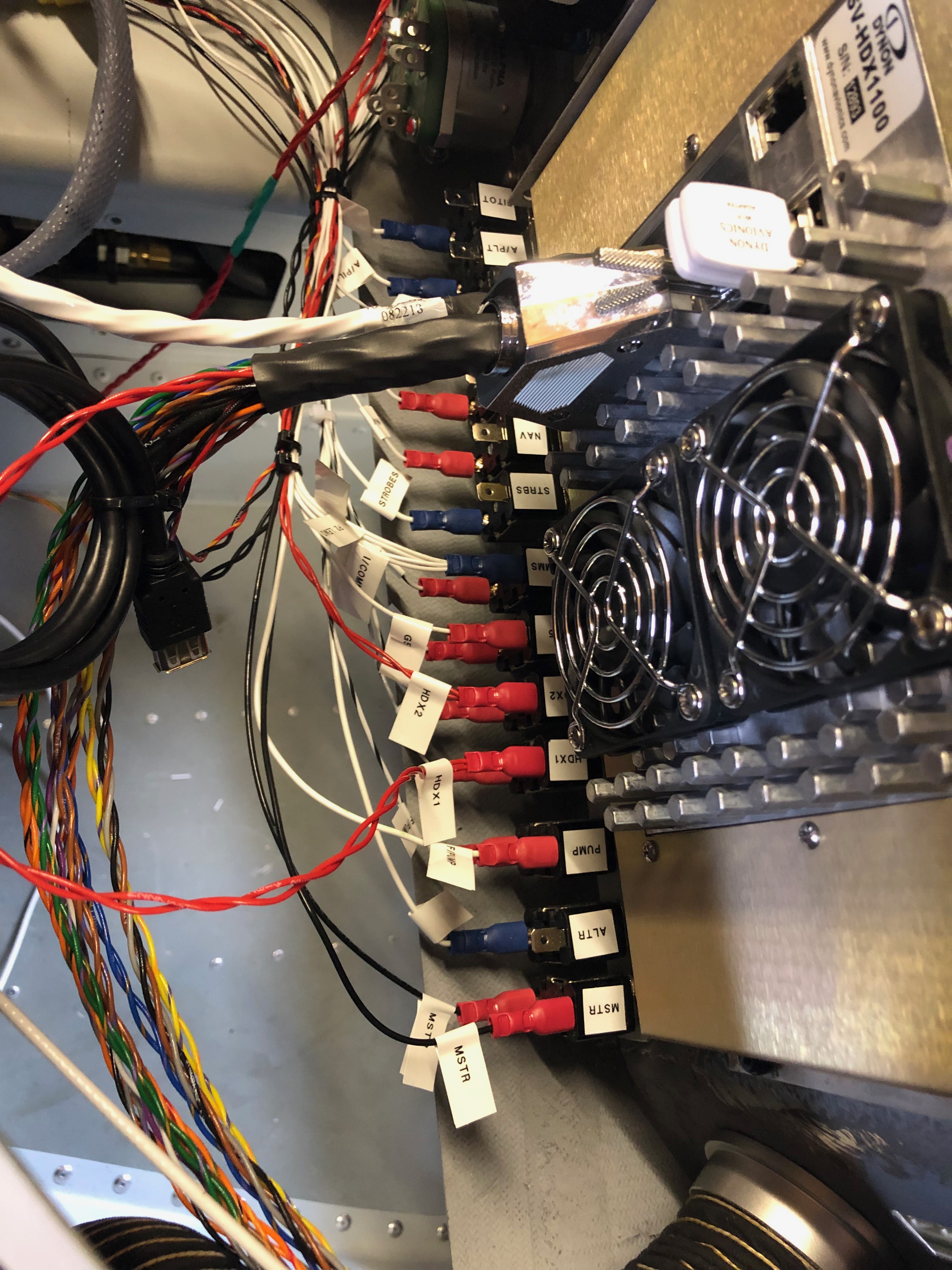
Work continues on the wiring today (and no doubt for a few days more but got quite a lot done today having completed the Master, Fuel Pump, HDX 1, & 2, G5 and Radio circuits.

This is the loom for just one of the SkyView HDX screens. It looks intimidating on first looks but they all do something and you just have to work out where they go!
The difficult bit was designing the electrical circuit to power all the devices. As I’d fitted the circuit breakers and switches and fitted the interconnecting wires it makes it quite easy to complete the circuit.
It’s getting quite busy…
so I’m starting to arrange the wire bundles in an orderly fashion as planned.
This is the Wig / Wag controller that I bought from the states to give better visibility whilst flying. It allows the landing lights to be steady, flash alternately or flash like a strobe. Just hope it works as promoted!

Tuesday 11th June 2019

Music: Röyksopp and Dido

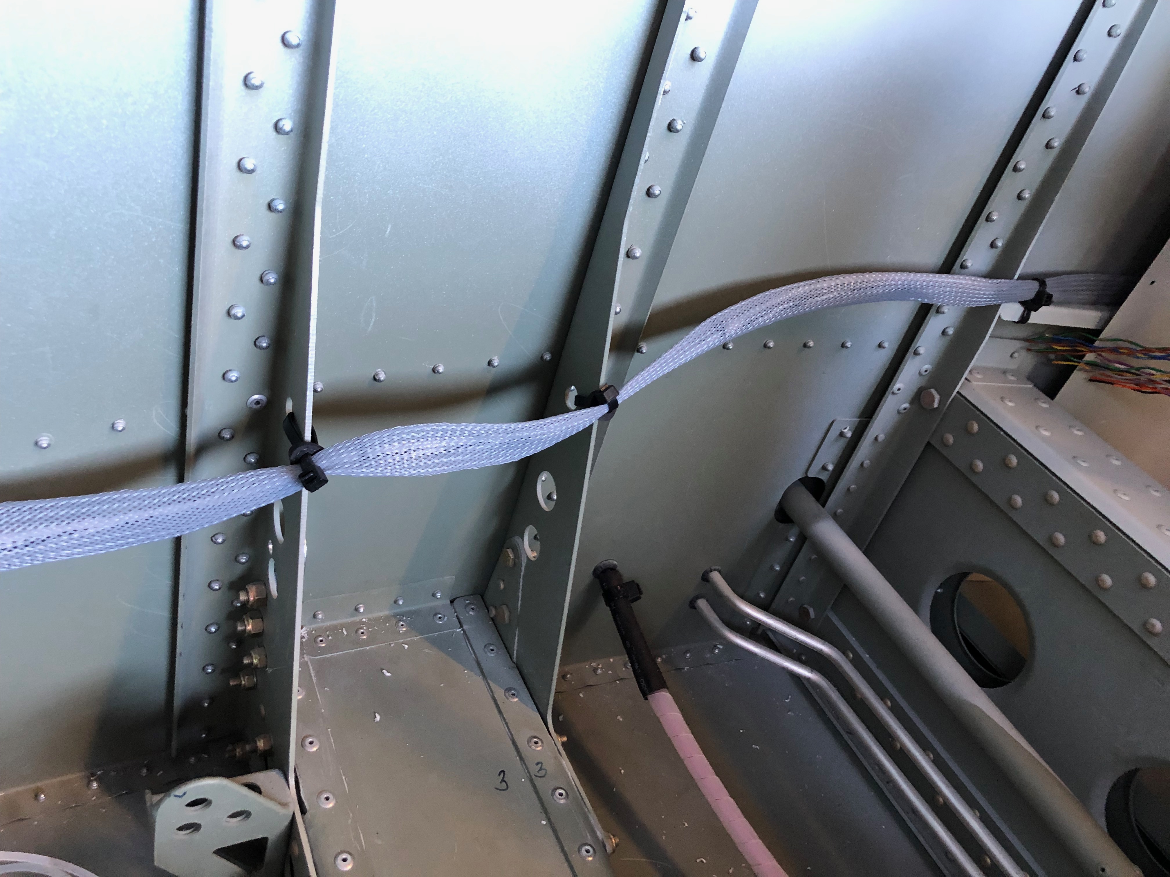
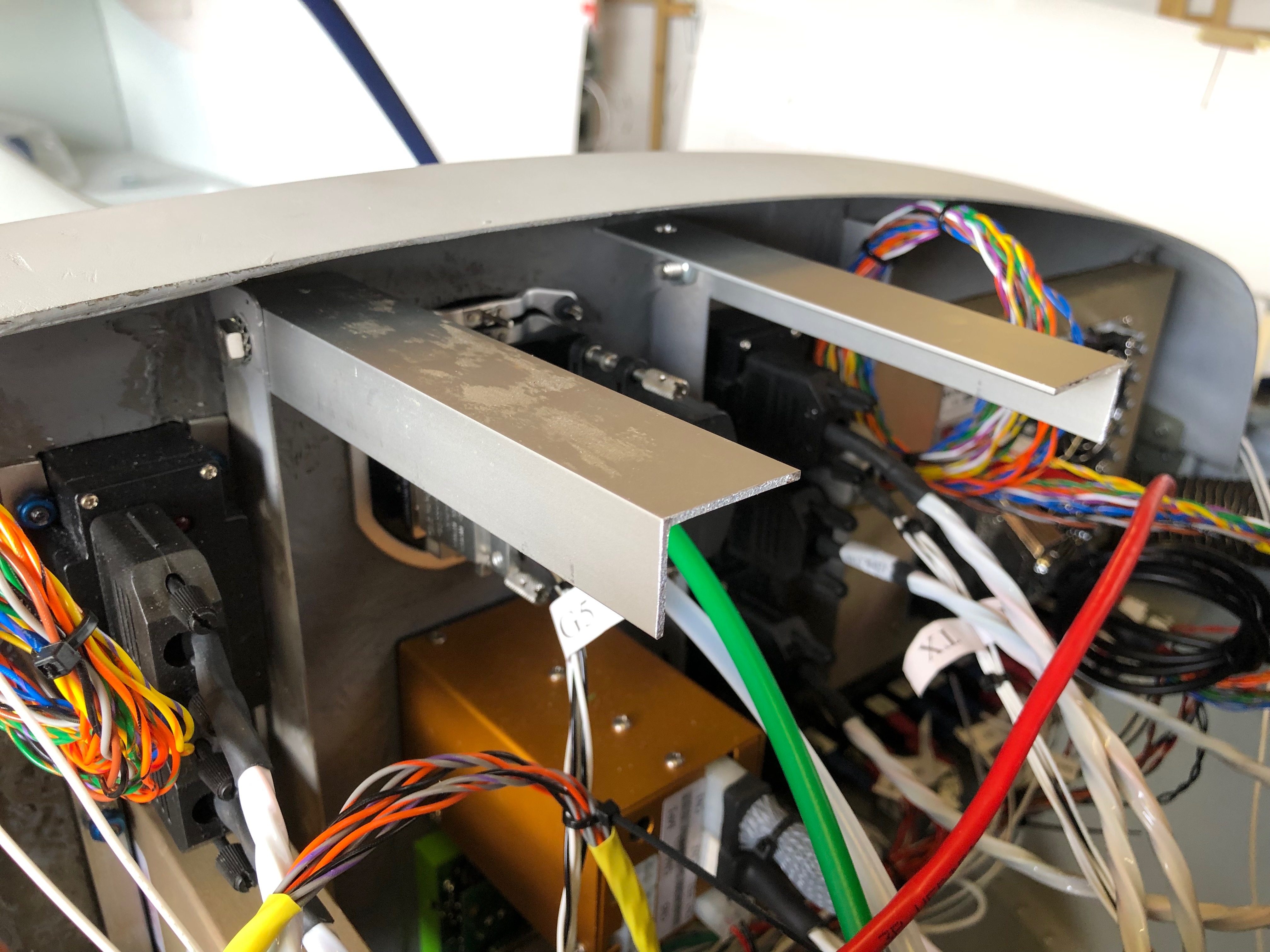
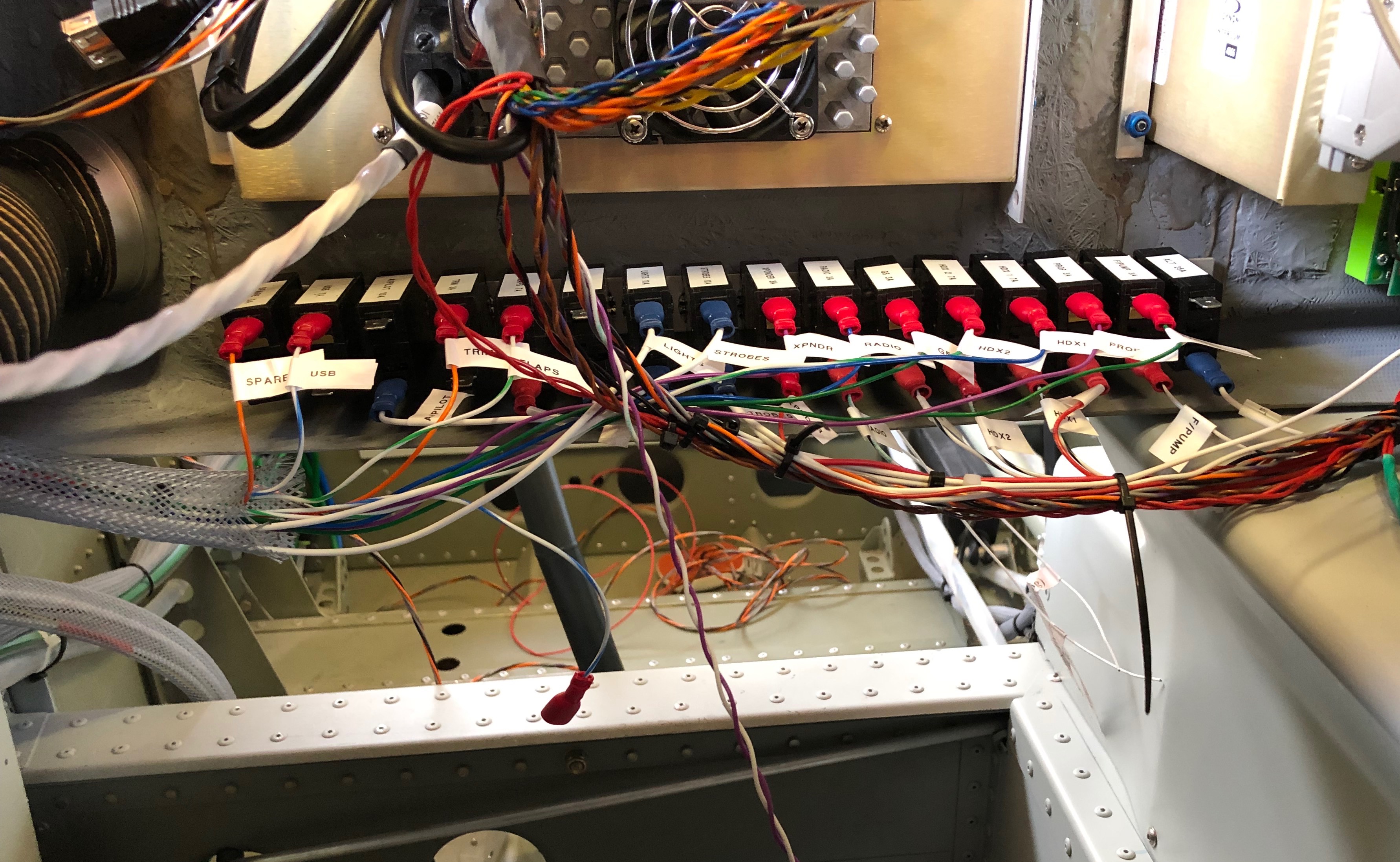
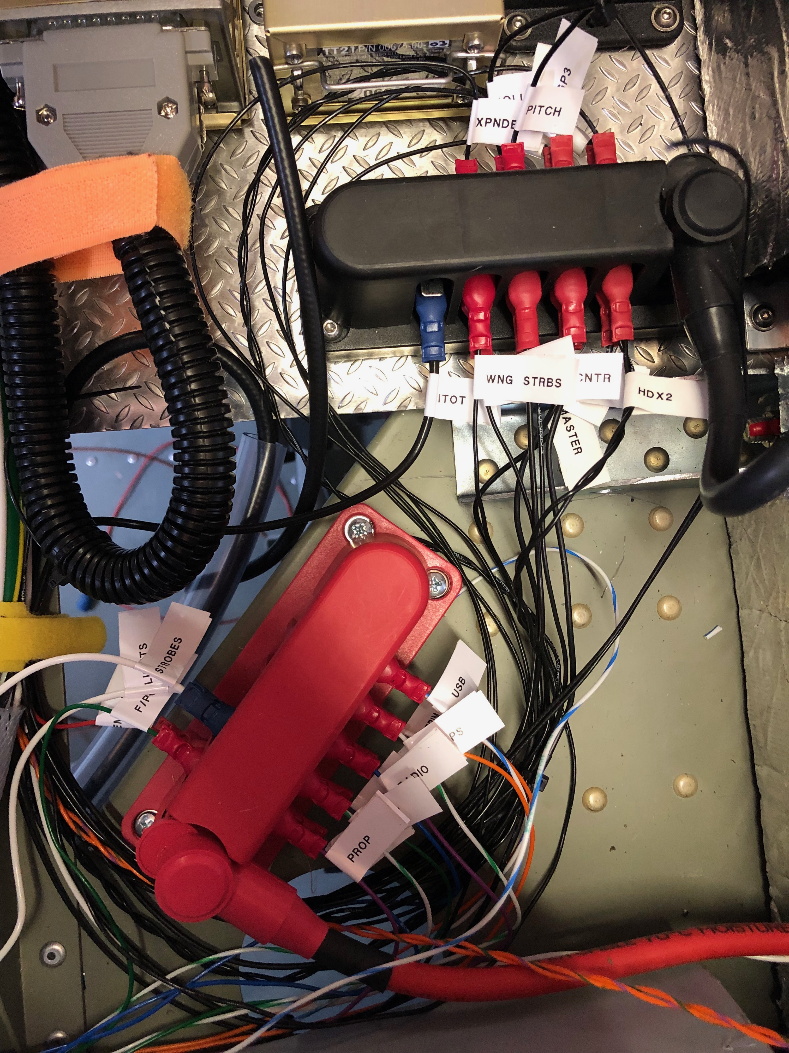
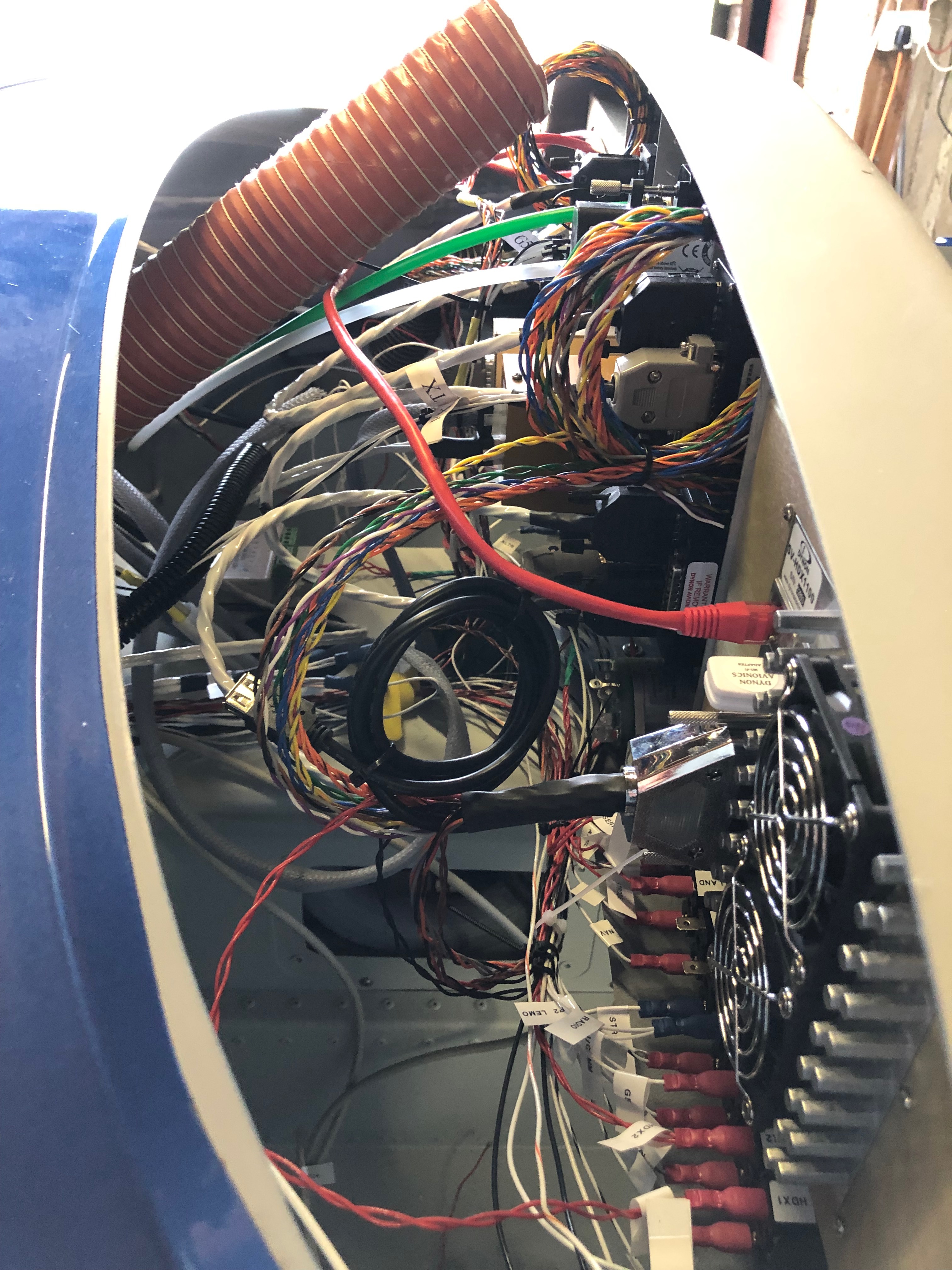
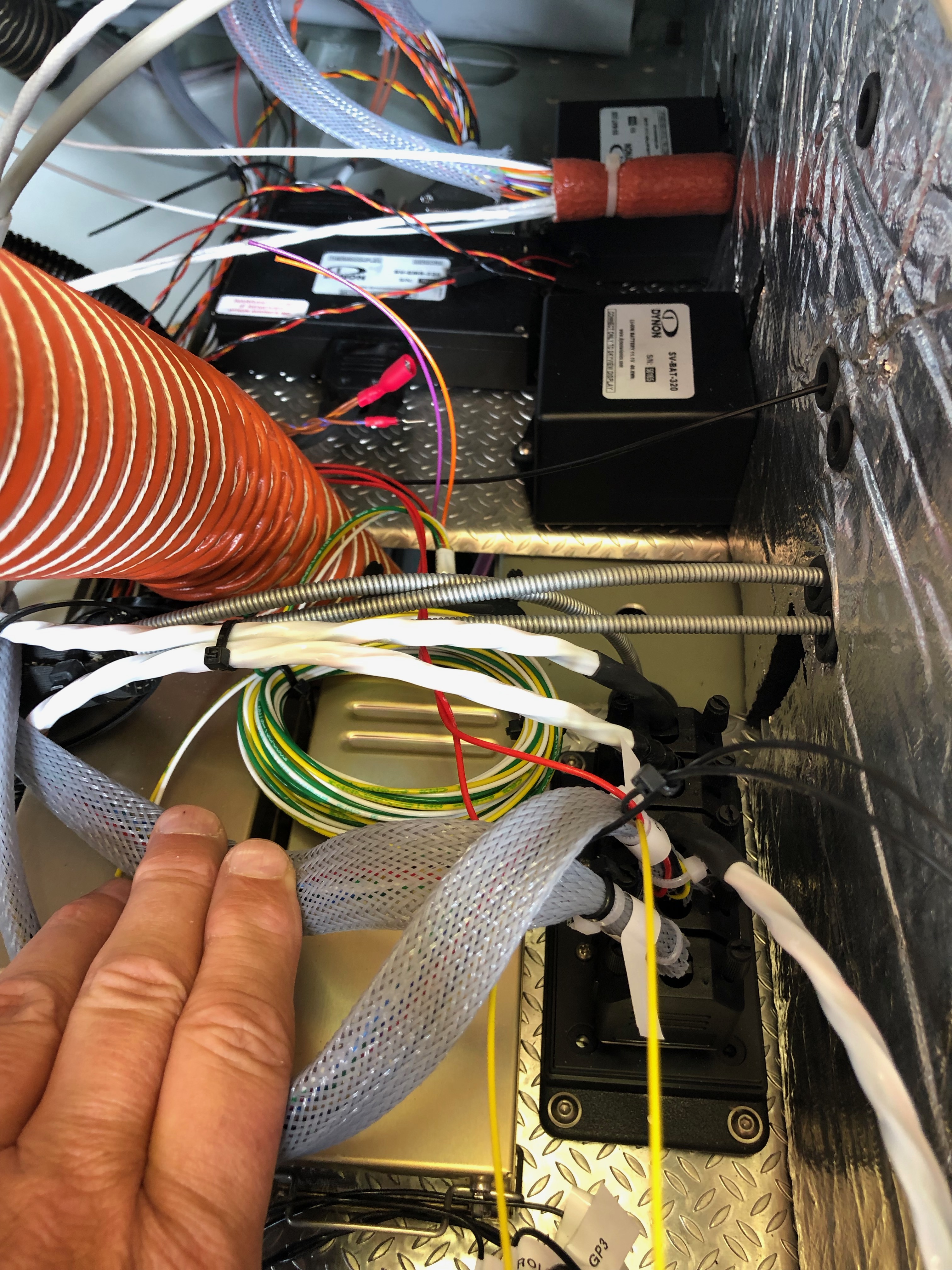
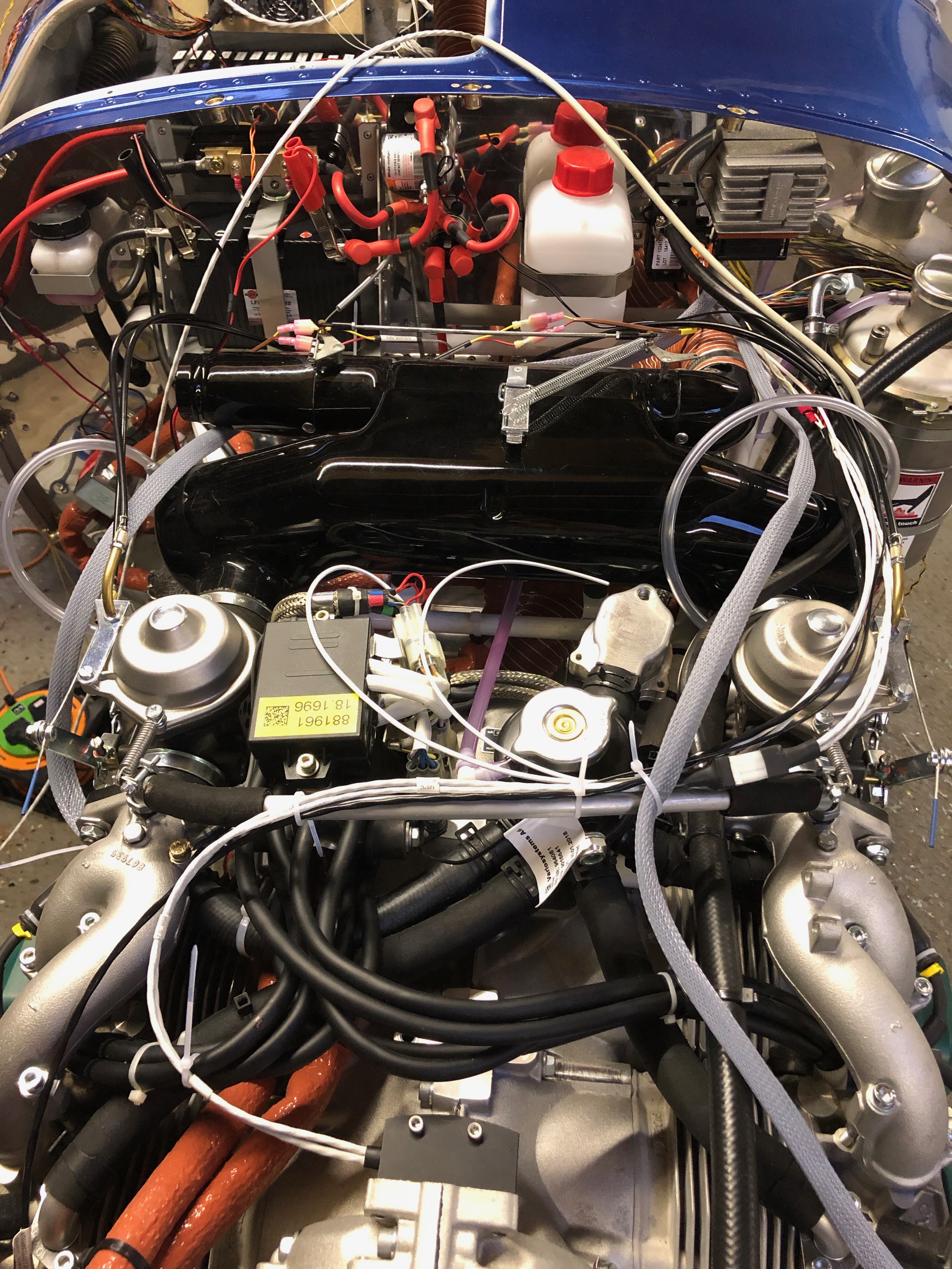
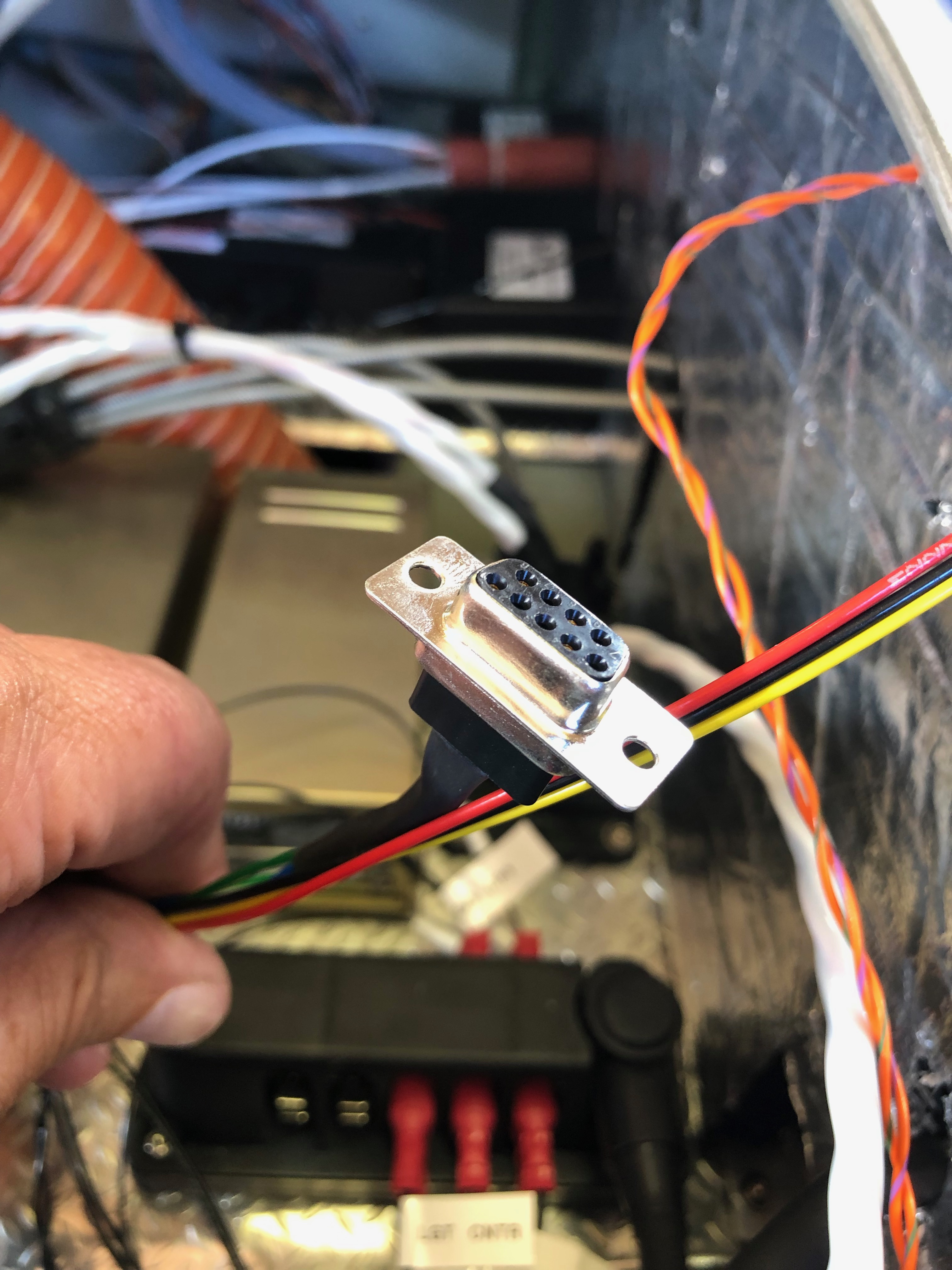
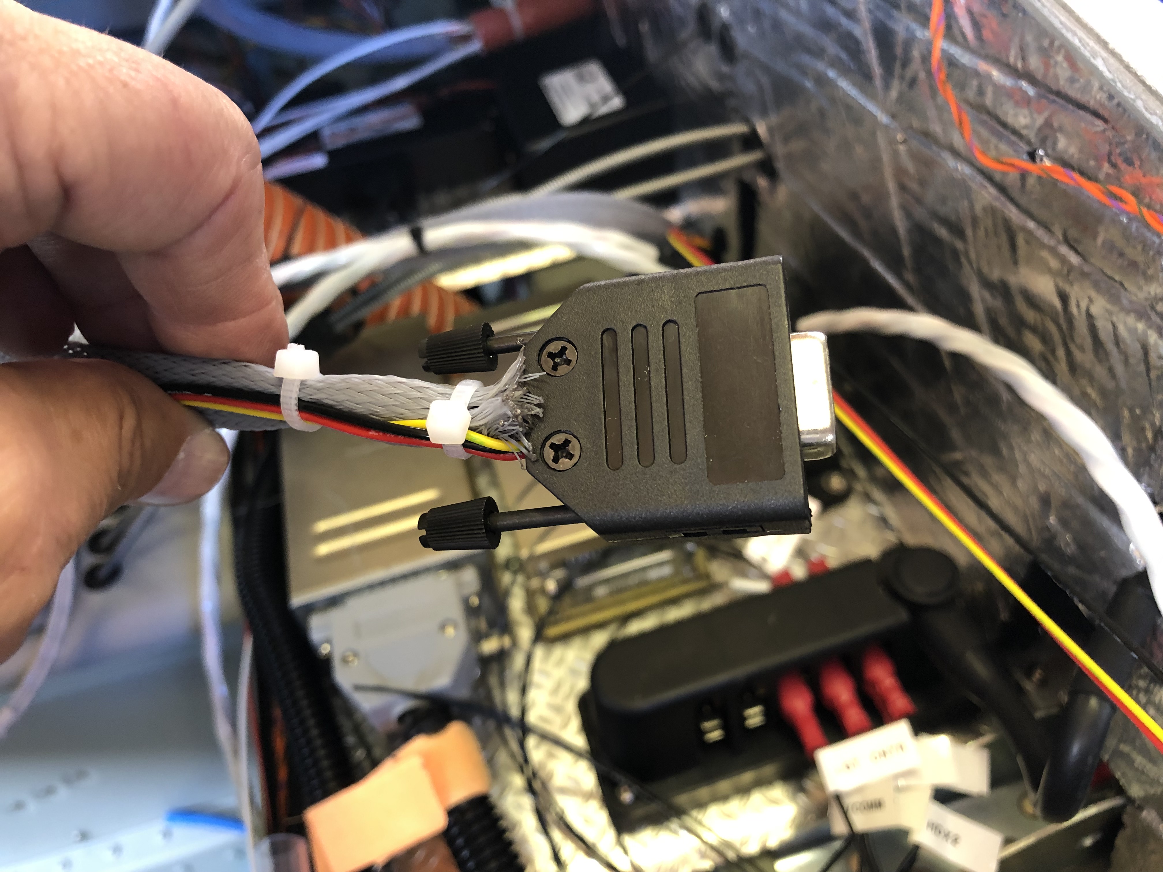
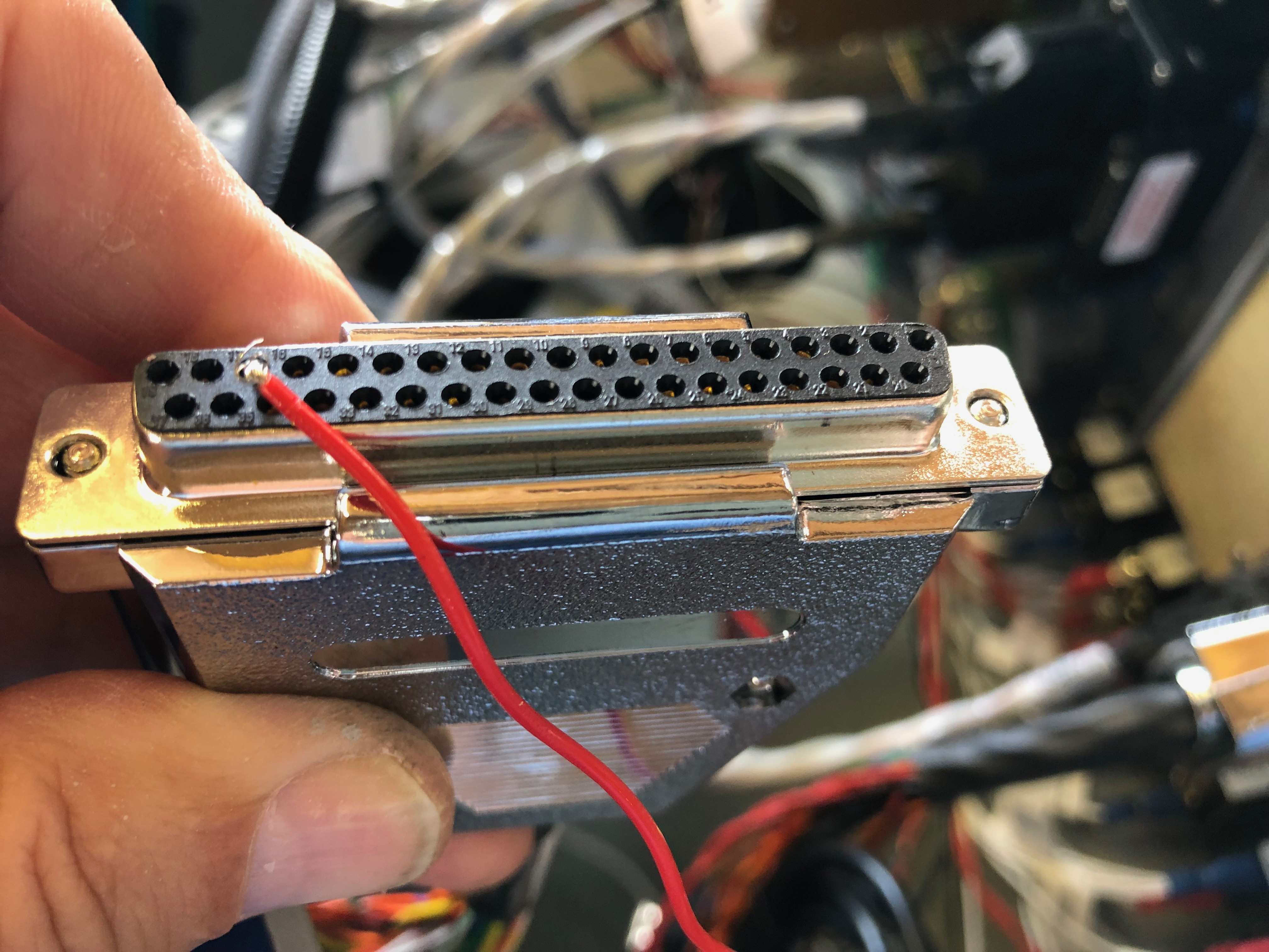
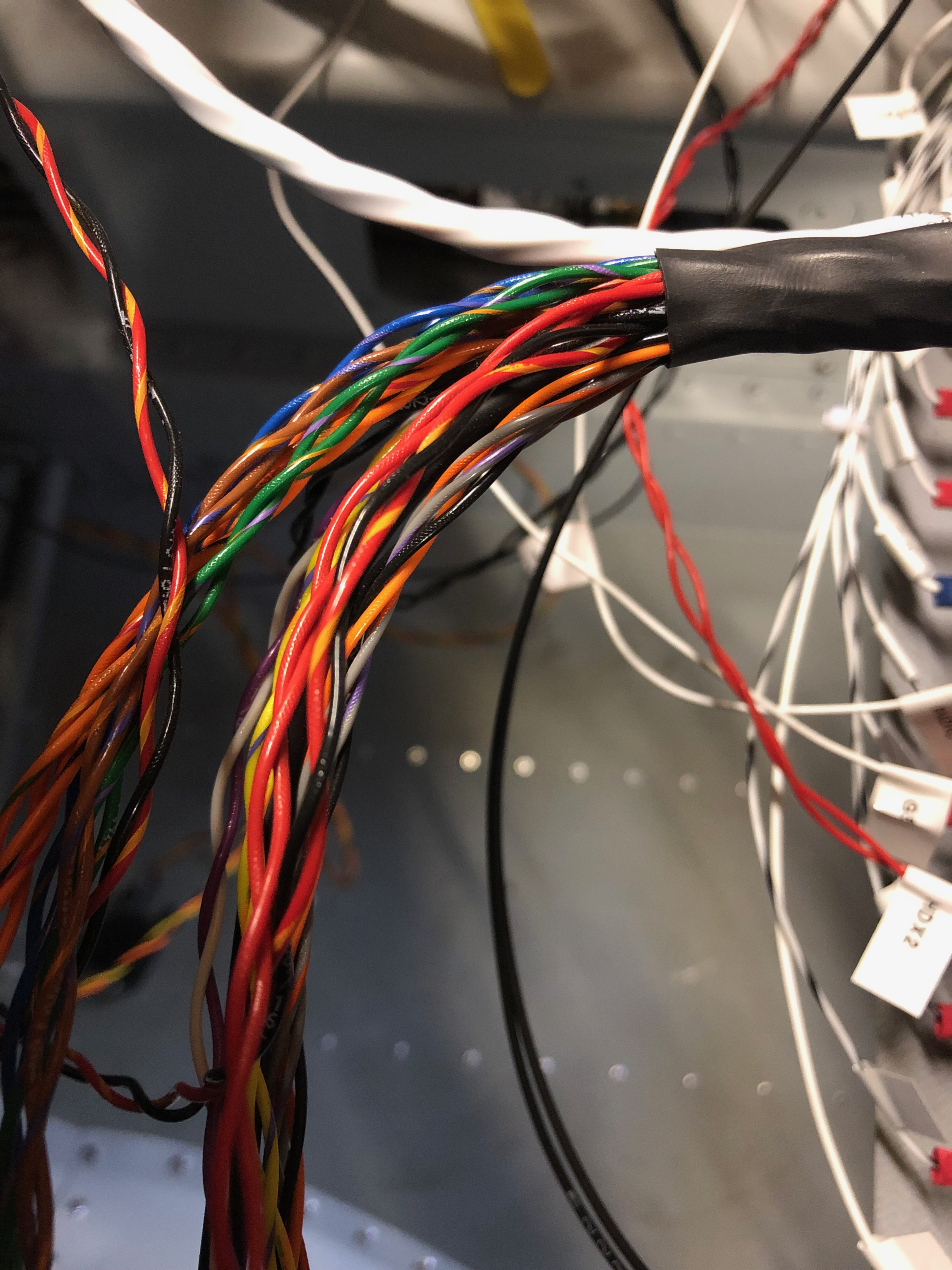
It’s time to do the wiring. This is going to be long job as there are wires all over the place! There are some things that must be done to make sure that it’s maintainable in the future like labelling as it’s easy to lose track of where wires are going from and to and obviously it’s got to look neat and tidy. First thing is to look at suitable routings for the bundles and make sure they make ‘sense’ then start laying them out. This is one of those jobs that you just have to keep going at and eventually it’s finished!

First up is to protect from reverse currents when the master switch is turned off. This is accomplished by placing a diode across the positive and negative posts on the battery contacter.
It looks a quite simple but it gets the job done.
One of the easy jobs is to run all the ‘earths’ back to the earthing block. After terminating each wire with a insulated female connector a label is attached to the lead. These are just printed off a electronic dymo babbling machine and seem to be suitable for the job.
Once the earth is connected, a quick check of the circuit logic and then I can temporarily power up the circuit.
Whilst the screen is powered up on main power I thought I’d update the system software to the latest version. The software has a boot loader that updates all the other attached devices like the autopilot and knob panel.
Last job today was to run the G5 to GMU11 loom in and secure in place.