Music: Songs to sing in the car! (Quite a good Spotify playlist)
Although I had some more connectors to attach onto various wires Ian had some time this morning to help me make a support platform for the ADAHRS unit. As I’ve decided not to have any traditional gauges and used a Garmin G5 I need also to fit a Garmin GMU. So I also need to make a bracket for the GMU 11 unit.
After marking the bracket out on a sheet of T3 aluminium Ian uses some metal shears to cut out the outline.
Some of the cut outs for the tabs are difficult to use the shears on so a hacksaw is used.
Angled tabs are added along the length of the unsupported sides to provide strengthening.
Now for my turn. This one is for the Dynon ADAHRS unit.
The bends in the bracket are made by clamping the sheet metal in a metal bender and using an aluminium bar to bend the sheet up.
Once bent the tabs need to be cut…
and bent back to provide the strengthening support.
The finished units trimmed and drilled ready to be etch primed and installed tomorrow.
Today I continued to fit the Superseal connectors for the strobes, landing lights and trim motors. I had planned to fit the Aveo air vents into the instrument panel but I’ve found one to be defective so I will have to get them replaced.
I received notification from Airmaster that the controller and harness have been dispatched and should be with me by next Tuesday. That will allow me to install the wiring and install the controller so when the prop finally arrives it can be installed within a few hours. Shouldn’t delay the testing too much.
I continued to fit the Amp Superseal connestors. This is the female socket which had the the waterproofing seal. They take quite a lot of time to make sure that the crimping is sound and the wires are married up correctly.
The Bristell includes a conduit to run the wires from the tail to the cockpit area which makes running wires easier.
The trim power supply connector on the port side. After running the cable into the cockpit I realised that their was a chance of chaffing during service…
so decided to run the cable inside some poly tube to prevent it. However I didn’t really think this one through as I need to run are wires from the wing in into so I’ll order some bigger poly tube.
This was the idea which was sound in principle…
and allows the cable to be run into the cabin very easily.
Next, is to make a start on the landing light and strobe connector. Unfortunately I didn’t get chance to finish them off but will do them Thursday or Friday.
Music: The Greatest Showman reimagined and Snow Patrol.
Finishing off the insulation installation, first fit of centre console, autopilot servo install and filling brake system with Aero Shell 41.
One quick job this morning now all the other pipes have been fitted is to run a piece of piping from the water expansion chamber to the water bottle.
I have been given templates for the insulation so I can cut them to size without too much effort.
Some notches, cuts and holes need to be made to make sure it sits properly on the firewall.
It’s a tight fit behind the rudder pedals which makes it difficult to handle once the backing paper has been removed.
The final pieces are fitted around the heated inlet.
The finished insulation, hopefully this should reduce noise from vibration of the firewall and the engine.
Now the servos brackets are in position the servos can be fitted. First the roll servo.
It’s very fiddly and would have been much easier to fit the servo to the bracket whilst it was out of the aircraft.
The pitch servo with the movement limiting bracket fitted which stops the motor running over centre. I still can’t finish the installation as there were items missing from the kit supplied to me – very frustrating as I can’t refit the controls until I fit the roll servo arm.
A first fit of the centre console in readiness for the fuel selector. Need to check with the instrument panel in place to check that the flap control cable is long enough to fit on the panel otherwise is will need to be mounted here instead which I would like to avoid.
After fitting the insulation need to reconnect and tighten the brake hoses before filling.
The brake fluid is filled from the bottom so some plastic pipe is wire locked onto the brake calliper nipple so stop it slipping off. The nipple is unscrewed to allow the fluid to flow into the calliper.
An oil can that has been thoroughly cleaned is filled with Aero Shell 41 and the plastic pipe is fitted to the nozzle.
The filling commences after releasing the park brake valve.
When the fluid reaches the brake oil bottle the brake calliper nipple is tightened and the process is repeated for the lefthand side brakes.
Filling complete but some air bubbles are present. They will need to be purged before use otherwise the brakes may not operate properly.
I took delivery of the servo brackets and wing locker fittings after a lengthy wait. Unfortunately bit were missing, again. The servo arm, bolts, washers and some rivets were missing from the servos mounts and the nuts, washers and large screws for the locks were missing from the wing locker kit. It can be very frustrating and delays the build.
Despite this at least I was still able to mount the servo brackets. During the install I found myself like a contortionist whilst I installed the brackets and front trim panels with an air rivet gun.
I spent some time this morning making sure that I can get to all the screws once installed. The cut outs are for the EFIS backup batteries. The insulation is fire resistant and will provide sound proofing too. It is secured into position by a self adhesive backing.
The install consists of 2 brackets one for roll and one for pitch. To install them I will need to remove the controls.
There’s quite a few nuts and bolts to remove including those holding bearings.
The control assembly, sometimes it feels like you’re dismantling the aircraft instead of building it when you have undo some of the work you’ve already done.
Now the area is clear I can start to install the brackets.
The bracket is positioned and 4mm holes drilled through the floor of the aircraft.
From underneath 3 holes are drilled which will further secure the bracket.
Ian Daniels has kindly lent me his air rivet gun and compressor which should make installation a little easier.
Once the holes are de-burred, and anti corrosion jointing compound is applied the bracket is cleco’d in place and riveted from below.
The final bracket installation. Once I have the rest of the missing bits I’ll be able to complete the roll installation.
To enable the installation of the pitch servo bracket 3 rivets need to be removed. The first thing to do is knock the centre hardened pin out…
and then drill the head of the rivet off and then know the rivet out.
The bracket is placed and checked that it’s positioned correctly.
One of the rivet holes don’t quite line up which is surprising but will need to be drilled out to enable it to be riveted.
Ian Daniels come to the rescue again as he lent me this 90 degree drill attachment that allows me to drill the hols for the rivets. There isn’t enough space to drill the holes without this.
The pitch servo riveted in place. Quite please with the bracket installations but they take a lot of time and I’ve still got to re-install the controls!
So I can install the insulation in the door wells I need to install the forward trim as they are riveted in place. It’s a tight fit behind the rudder pedals but they can’t be fitted until after the rudder pedals are fitted as there is insufficient room.
The air rivet gun makes it easier to get to the rivets but because it’s size I won’t be able to use it for all the rivets…
So for some I need to use the hand rivet gun but it’s very awkward to use in such a tight space.
It took some time, longer than expected however the left panel is in…
and so is the right. Tomorrow I will refit the controls.
Andy has come to visit for a couple of days and give me a hand on some of the items that need 2 people, like lifting and turning the wings. One of the jobs that would be good for us to start on was carrying out the final fit of the lower cowl that needs modification to gain access to the fuel check valve and ensure that there is sufficient clearance around the radiators and exhaust is service.
Once the cowl is fitted the ‘tight’ spots need to be marked.
Also the position of the hole for the gasocolator fuel check valve is marked.
The cowl is made from carbon fibre so the tight spots are filed with a course file to start and finished off with wet and dry.
The cowl is also adjusted for the exhaust downpipe.
Next a hole needs to be drilled in the cowl for the drain valve.
and opened out with a step drill.
Plenty of room now so no chance of rubbing against the exhaust…
… or the water radiator.
The hole is in a perfect position but will need to be opened up further.
The Rotax installation involves running hoses and tubes from everywhere, to everywhere. One of the last tube runs are the drains from the carb drip trays and the air box plenum.
They need to be run to exit underneath the fuselage but miss all the hot spots like the oil, water and exhaust pipes. it’s not straightforward.
But Andy has done a good job.
Meanwhile, I finish off designing and installing the equipment tray retention system which will be rubber mounted to dampen vibration and protect the avionics units mounted on it.
One down and one to go tomorrow…
Andy taking the captains seat as usual after a very productive day.
Not a lot of action today as I was looking at the avionics kit to see where it can all be mounted so just mounted the VHF aerial.
The top surface just behind the canopy is already drilled for VHF whip aerial.
The aerial to be fitted has a BNC coaxial connection on it’s base that can be accessed from within the rear cabin.
The screws that fix the aerial onto the fuselage have cup shaped anti shake washers to hold them.
To ensure that water doesn’t make its way past the screws and down the threads I’ve used some silicone to seal them before tightening them.
The finished installation after running some silicone sealer around the base of the aerial.
To get an idea of how the avionics connect together I laid it out and connected it up. I’d already charged the backup batteries up so they allowed me to power most of the system up. The ADAHRS, Servos, Radio and Transponder can’t be powered up as it needs wiring but it gives me a good idea of how it can be laid out in the Aircraft.
A number of jobs planned for today. Complete the engine NACA ducting, install the clevis pins to the carb heat control and cabin heater, install the fuel pressure sensor, install the engine intake air box, install the MAP sensor pipe, adjust and set the cowl quick release fasteners and install the control stick torque supports.
The fuel sensor and adapter were left to set with Loctite 577 overnight so can now be fitted to the fuel hose that I had added for it.
The hose is secured with a hose clamp and fire sleeve is added which is secured in place with locking wire.
The sensor is secured against movement and vibration with a stand-off.
These are the clevis fittings that are used on the carb heat, cabin heater, screen de-mist and park brake.
Now the sealant is set, the air box is mounted on a couple of brackets off the engine mount. It’s secured with a couple of Nyloc nuts underneath. Two short pieces of sturdy rubber hose are fitted over the carburettor inlets and the air box and provide a flexible joint between them.
They are secured in place with jubilee clips.
The SCAT ducting is secured in place with jubilee clips to the air box intake and the starboard lower cowl side NACA duct.
The ducting to the port NACA duct is run to the rear of the exhaust and then into the centre inlet on the heat exchanger, secured with jubilee clips and held in position with a couple of tie wraps.
Port NACA duct.
Even with all the space that the Bristell has It can get a bit tight with all the hoses that are required.
The MAP sensor has already been mounted so just needs a pipe to be run and of course some wiring at a later stage…
I’ve used 5.6mm ID R9 fuel hose between the carburettor balance pipe and the MAP sensor.
The quick release fittings on the fuselage have been riveted in place and now require them to be adjusted and set. First thing is to screw them in…
until they are flush with the cowl.
Once adjusted the pin can be pulled that sets them into position.
They are released by a quarter turn of the Philips screw and the fitting stays set in place.
I still need to repeat the process for the top cowl and the oil inspection cover. Ian will be installing the fittings during next week. Unfortunately the rivets need to be ‘squeezed’ and I don’t have the tool to do it.
Now I’ve picked up the control stick torque arms I can start work on the control sticks.
The fittings need to be checked and secured although they will need to be adjusted when the wings are fitted to centralise them, set the limit screws and check aileron deflection are correct.
The torque arm is attached at one end using the bolt from the control stick bearing.
The other end is secured with a 4 x 15mm rivet.
Both torque support arms fitted, completing a fairly productive day.
I’m still not 100% sure on the layout of the screens and associated control panels so I thought it would be good to add the pilot seat so I could check different layouts.
Once the seats were installed I could sit in the aircraft as I would normally fly it. The panel here has most of the bits I need but is missing the flap switch, some warning lights and the air vents.
I’ve stuck the pictures on using glue dots that allow me to move the pictures about. I can then do a ‘touch’ test on the layout to see what works best.
Monday was set aside to travel to Chilsford Farm to collect some of the outstanding items from the kit. So today I could get on with a lot of jobs that had stalled because of the shortages.
On Friday I sealed the canopy perspex with silicone and left it to set. The waste material was removed with a plastic scraper.
And cleaned off with some methylated spirits.
The result is good but not perfect in a couple of places so will need some attention once the canopy is mounted.
Next up is to connect the NACA ducts to the various intakes on the carburettor and cabin heater.
The SCAT ducting for the air intake is secured with a jubilee clip onto the air intake.
The ducting is cut to size and attached to the rear of the righthand NACA inlet on the lower canopy.
The heat exchanger is positioned and secured in place with large jubilee clips.
A short piece of ducting is installed between the heat heat exchanger and the heater intake that runs through the firewall to provide cabin heat and a de-mist facility.
A long pice of ducting is connected to the heater control and will eventually connect to the glare shield that includes the de-mist vents.
The lefthand side ducting runs from the NACA inlet to the middle heat exchanger connection but it’s quite tight so it must be routed so it doesn’t come into contact with the exhaust system.
View from the righthand side.
A spring is cut and installed to ensure that the air intake is supplied from the cold air vent by default.
One of the items I picked up on Monday was the pitot mount. I’ve already taken delivery of the avionics so I can mount the pitot onto the mount.
Instead of drilling holes and using screws I’ve decided to secure the probe into position with silicone which will provide a neat solution.
Once filled with silicone it’s left to set overnight.
The carburettor air box has two ‘horns’ that the SCAT hose connects to. They require sealing with heat resistant silicone and secured with three rivets.
The finished air box which will be left to set overnight.
The cabin air vents are supplied with fresh air from NACA ducts in the side of the fuselage. They require installing in the instrument panel and then connecting up with some scat hose. So a temporary fit of the panel is required to get the hose length.
Two brackets are clecoed into position and the panel is secure by two screws each side.
With the panel installed it give me an idea of the space I have for the avionics and possible positioning. Tomorrow I will fit the air vents and hose.
One job left over from installing the fuel system is to fit the fuel pressure sensor. The sensor cannot be connected directly to the hose. A 1/8″ NPT female to 6mm barb adapter is required.
As it will come into contact with fuel Loctite 577 is used to seal the thread before fitting.
The pressure sensor and adapter before being screwed together. They will be left overnight to set.
The final job for today was to trim the cowl to ensure is doesn’t come into contact withe the water radiator.
Finishing off the panel modification today and the start of the landing lights.
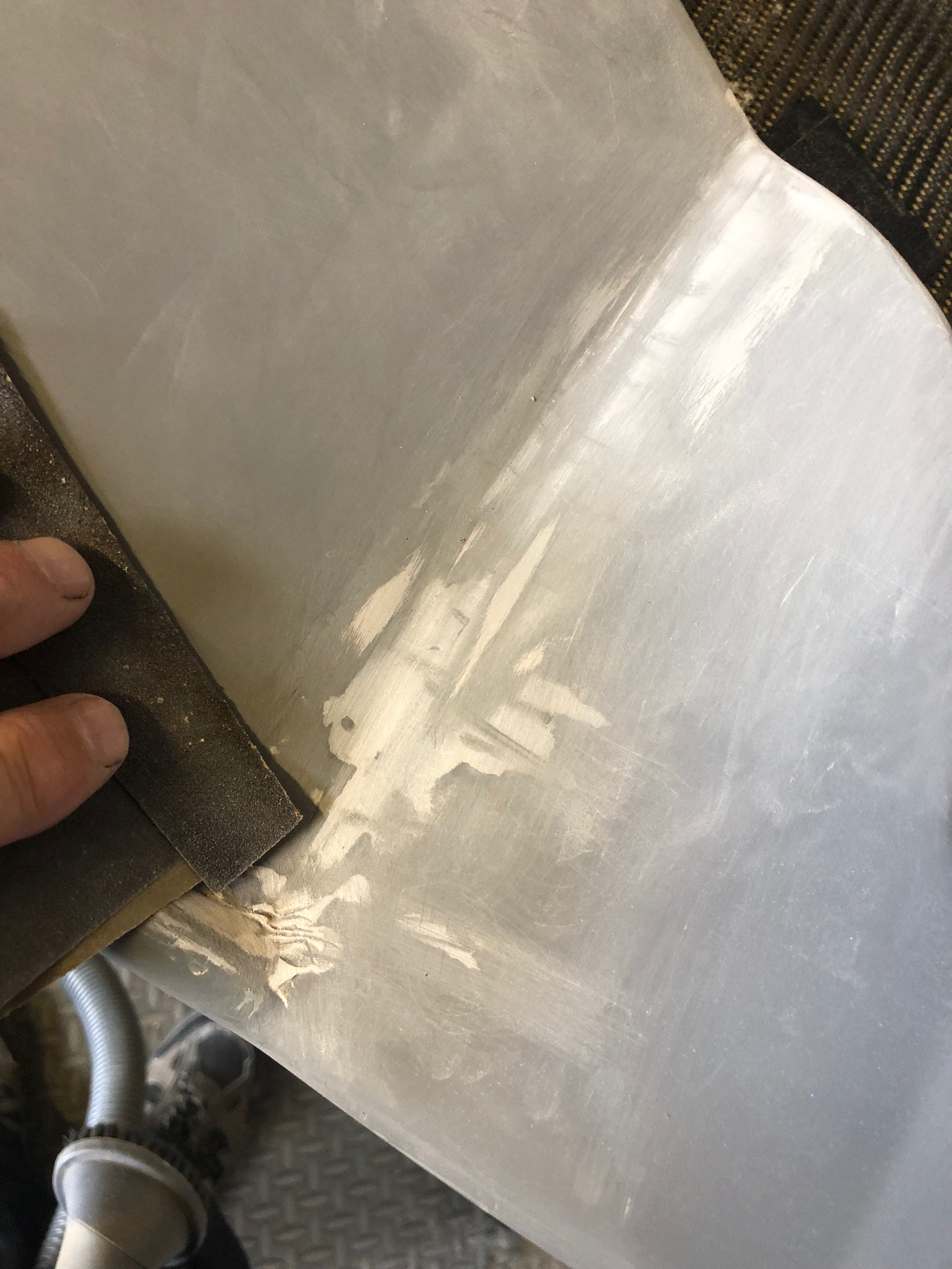
There were a couple of areas where I needed to use filler and then sand with fine wet & dry.
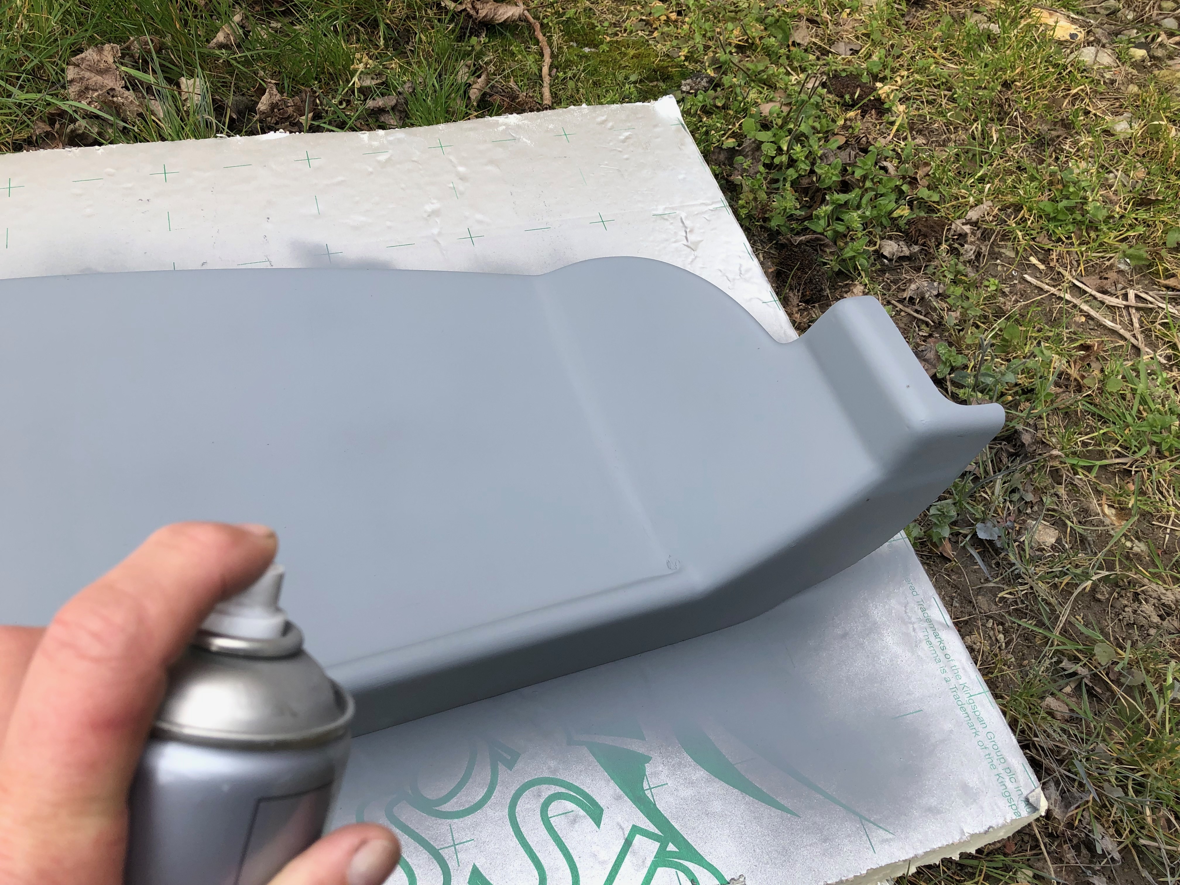
Primer is applied and is ready for painting.
Ian was back today after a few days away and gave me a hand to get a wing up on the stands so I can install the landing lights, wire the trim motor and fit the strobes.
The LED units are installed in both wings.
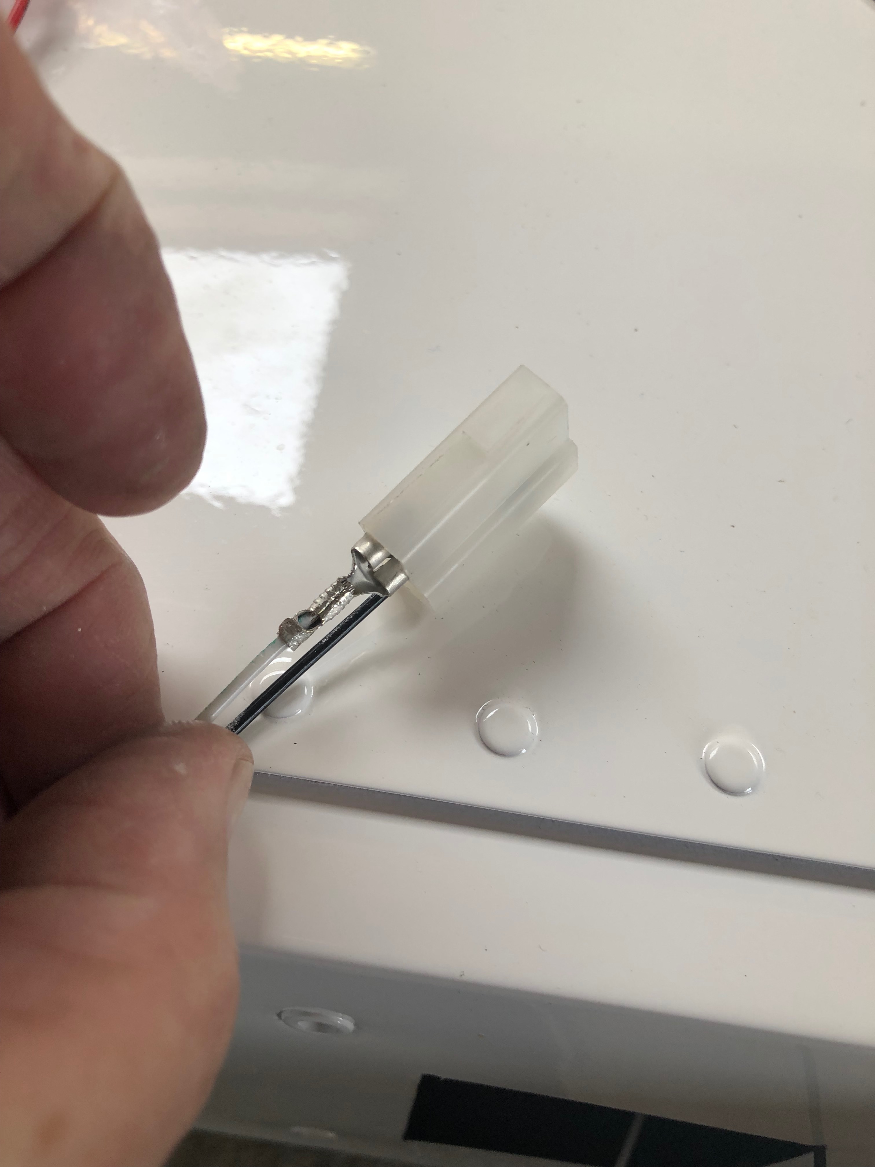
The wires are shortened and connectors are crimped and inserted into the connector block.
The unit is secured into place with M4 screws and then checked to ensure they work!
The light cover is secured into position with tape…
and six holes for the M4 countersunk rivnuts are drilled…
and countersunk. The rivnuts are then installed…
and the light cover is fitted and secured into place with countersunk stainless steel screws.
The interesting thing about building this aircraft is the number of activities and installations that need to be done that I’ve never done before. It takes a little thought to work out how to approach the task before starting but once completed successfully it gives you a great sense of achievement and satisfaction. The modification of the panel using glass fibre matting and resin is one such job. I knew what I wanted to achieve and now it’s complete I’m really pleased with the result.
This was how I left the panel yesterday. Now fully cured the fibreglass needs to be built up.
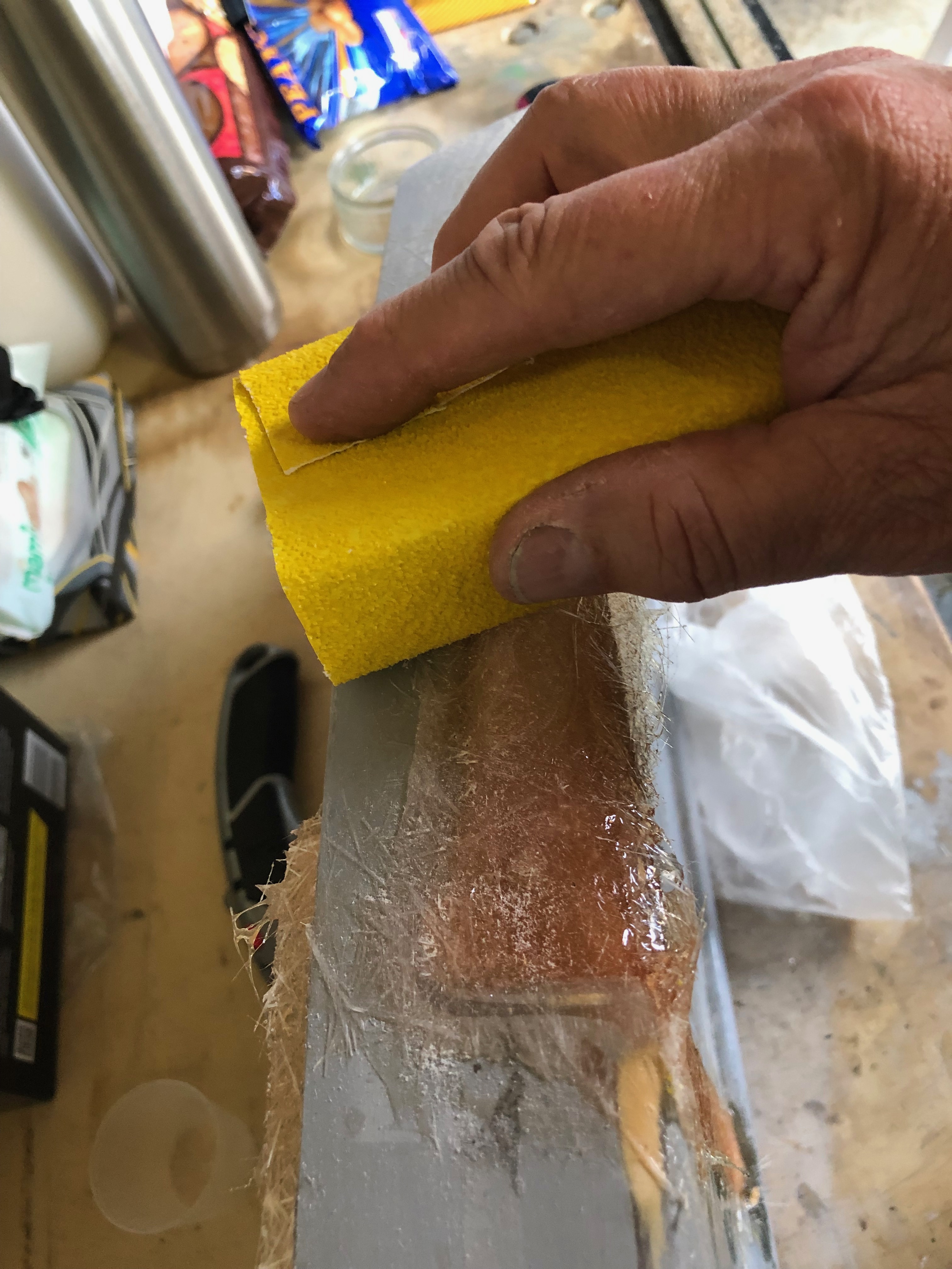
The area to be built up is wetted with resin and a layer of glass fibre is added and coated.
Once dried in around 30 minutes the area can be sanded down.
The rear of the panel ready is now complete but the front face needs to be filled with P38.
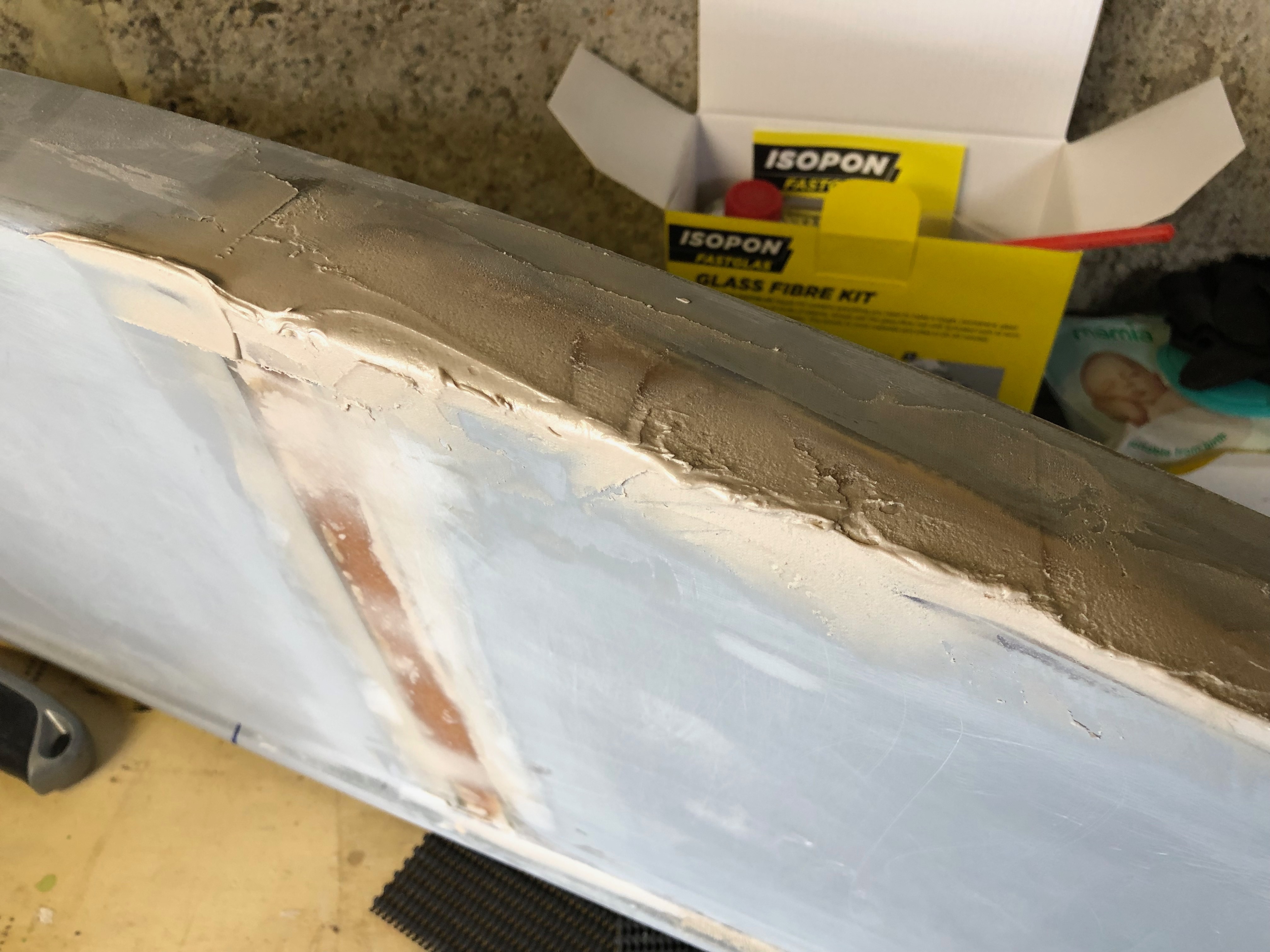
I used an Isopon glass fibre kit to bridge the gap and support the joins and P38 to fill and finish before painting with primer.
The filler is mixed using one golf ball sized ball of resin to one pea sized ball of hardener and mixed within 4 minutes. P38 sets in 20 minutes so you can’t hang around.
The filler is applied using a spatula and sanded smooth using 180 wet and dry. The process is repeated several times to remove any holes or dips.
The finished panel prior to painting. Apart from the different colour where the join is you can’t tell that it’s been modified. Very pleased with the result!
Following the build of my Bristell NG5 Kit No. 382 Registration G-MLSY