Today was a little frustrating with news that the ignition switch wouldn’t be delivered until August! Grrr…
Well the day was dominated by checking up on another vital component, the ignition switch. After placing the order with a reputable aviation company I was told there would be a delay as they were out of stock (despite their system saying that they had them in stock). They advised that I would receive the switch on the 22nd May which I agreed to. As I hadn’t heard anything from the company I checked with them on Wednesday. They said ‘don’t worry sir we’ll drop you a line and let you know today’. Well that was yesterday and nothing! I phone them today and they said ‘don’t worry sir we’ll drop you a line and let you know today’. Surprisingly I said No! give me a call as soon as you have checked. 20 mins later and the voice on the other end said ‘It’s not good news sir – expected delivery is now August!’ I do find it amazing that customer service doesn’t seem to feature at all in some companies operation and they just don’t keep customers updated with any delays. I won’t name the company as it’s happened more than once during this project with different suppliers. 2 hours later and I found another supplier. It’s been despatched within minutes of placing the order and it’s on its way from Germany with delivery due in a couple of day. With all the holes I’ve cut in the panel it needs a bit of support! I had a think and believe this to be the best solution. I’ve cut a couple of pieces of 25mm aluminium angle and drilled loads of holes in it so it will ‘key’ onto the structure better. I’ve also drilled some holes in the side of the support braces so I can use them to secure wires behind the panel with some cable ties. The angle is secured in place with glass fibre cloth.A layer of glass fibre is set first that the support will sit on and then another layer of glass fibre is set over the top. This should provide a very strong bond.This is how it will look once finished. Another layer of glass fibre needs to be laid over the outer supports to finish off but I’ve run out of time today due to the switch fiasco so will finish of tomorrow!
The trim indicators and manual prop switch holes need to be cut today. I’ve also ordered the paint for the panel that matches the interior panels, it should be ready tomorrow morning so I’ll paint it once I’ve cut the rest of the holes in the panel.
Same procedure to cut the holes for the trim indicators. Finishing the holes with a file.A trial fit of the indicators. Looks about right.The panel and centre console installed to trial cable runs. Looks quite good even if i say so myself! With all the cut outs I need to strengthen the panels I’ll attach some aluminium angle behind the panel with fibreglass.The final control to be installed is the manual switch for the prop. The cut out is made in the same way but I’ve decided to install this control in the centre console just in front of the throttle.
I have the Garmin G5, Airmaster prop controller, Flap switch and the Dynon sub panels to do today. The sub panels cut outs aren’t just rectangles so I need take my time and as they say measure twice and cut once. In reality I think I’m measuring 4 or 5 times and cutting once which is taking some time but it’s got to be right otherwise it’ll spoil the look of the cockpit.
The G5 and prop controller need 79mm and 57mm holes so these are needed to get a neat hole.I’ve finally decided on the layout. This look like the best option with the panels that I need to install. I’ve also borrowed an ignition switch from Ian to position on the panel before my one is delivered.Marking up the panel for the prop control hole, making sure that its equidistant between the G5 and the flap control. These are the easy holes to cut as they are circular and along a single line.This is the template that Dynon supply with their panels. This template is used for the 3 of the 4 cut outs.I’ve thought of different ways to cut the holes out. Jigsaw, Fretsaw and drill. Although I have very fine blades the jigsaw snagged when I used it on the main panel cut outs and I don’t have a jigsaw so small holes are drilled around the outline. Once drilled the material between the holes is cut with a Stanley knife. Once cut out fine adjustments are made with a file. The audio panel cutout at the bottom in this pic is the only one that’s a rectangle which made it easier but the template seemed to be too large so it’s lucky I measured the unit before I cut the hole!The first controller panel installed to test.The last job for today is to drill the hole for the flap controller and cut the plastic rod for the knob.Still a little long so another cut needs to be made.These pictures of the avionics have helped me visualise the panel layout before cutting and can finally be binned now all the holes have been cut.The instrument panel, with components installed. Quite pleased with it but it’s taken a lot of time decide on the layout and cut. Some more cut outs need to be made for the trim position indicators, Magneto switch and USB power.A late finish tonight. Looks like I’ve missed a lovely day!
A number of jobs planned for today. Complete the engine NACA ducting, install the clevis pins to the carb heat control and cabin heater, install the fuel pressure sensor, install the engine intake air box, install the MAP sensor pipe, adjust and set the cowl quick release fasteners and install the control stick torque supports.
The fuel sensor and adapter were left to set with Loctite 577 overnight so can now be fitted to the fuel hose that I had added for it.
The hose is secured with a hose clamp and fire sleeve is added which is secured in place with locking wire.
The sensor is secured against movement and vibration with a stand-off.
These are the clevis fittings that are used on the carb heat, cabin heater, screen de-mist and park brake.
Now the sealant is set, the air box is mounted on a couple of brackets off the engine mount. It’s secured with a couple of Nyloc nuts underneath. Two short pieces of sturdy rubber hose are fitted over the carburettor inlets and the air box and provide a flexible joint between them.
They are secured in place with jubilee clips.
The SCAT ducting is secured in place with jubilee clips to the air box intake and the starboard lower cowl side NACA duct.
The ducting to the port NACA duct is run to the rear of the exhaust and then into the centre inlet on the heat exchanger, secured with jubilee clips and held in position with a couple of tie wraps.
Port NACA duct.
Even with all the space that the Bristell has It can get a bit tight with all the hoses that are required.
The MAP sensor has already been mounted so just needs a pipe to be run and of course some wiring at a later stage…
I’ve used 5.6mm ID R9 fuel hose between the carburettor balance pipe and the MAP sensor.
The quick release fittings on the fuselage have been riveted in place and now require them to be adjusted and set. First thing is to screw them in…
until they are flush with the cowl.
Once adjusted the pin can be pulled that sets them into position.
They are released by a quarter turn of the Philips screw and the fitting stays set in place.
I still need to repeat the process for the top cowl and the oil inspection cover. Ian will be installing the fittings during next week. Unfortunately the rivets need to be ‘squeezed’ and I don’t have the tool to do it.
Now I’ve picked up the control stick torque arms I can start work on the control sticks.
The fittings need to be checked and secured although they will need to be adjusted when the wings are fitted to centralise them, set the limit screws and check aileron deflection are correct.
The torque arm is attached at one end using the bolt from the control stick bearing.
The other end is secured with a 4 x 15mm rivet.
Both torque support arms fitted, completing a fairly productive day.
I’m still not 100% sure on the layout of the screens and associated control panels so I thought it would be good to add the pilot seat so I could check different layouts.
Once the seats were installed I could sit in the aircraft as I would normally fly it. The panel here has most of the bits I need but is missing the flap switch, some warning lights and the air vents.
I’ve stuck the pictures on using glue dots that allow me to move the pictures about. I can then do a ‘touch’ test on the layout to see what works best.
Monday was set aside to travel to Chilsford Farm to collect some of the outstanding items from the kit. So today I could get on with a lot of jobs that had stalled because of the shortages.
On Friday I sealed the canopy perspex with silicone and left it to set. The waste material was removed with a plastic scraper.
And cleaned off with some methylated spirits.
The result is good but not perfect in a couple of places so will need some attention once the canopy is mounted.
Next up is to connect the NACA ducts to the various intakes on the carburettor and cabin heater.
The SCAT ducting for the air intake is secured with a jubilee clip onto the air intake.
The ducting is cut to size and attached to the rear of the righthand NACA inlet on the lower canopy.
The heat exchanger is positioned and secured in place with large jubilee clips.
A short piece of ducting is installed between the heat heat exchanger and the heater intake that runs through the firewall to provide cabin heat and a de-mist facility.
A long pice of ducting is connected to the heater control and will eventually connect to the glare shield that includes the de-mist vents.
The lefthand side ducting runs from the NACA inlet to the middle heat exchanger connection but it’s quite tight so it must be routed so it doesn’t come into contact with the exhaust system.
View from the righthand side.
A spring is cut and installed to ensure that the air intake is supplied from the cold air vent by default.
One of the items I picked up on Monday was the pitot mount. I’ve already taken delivery of the avionics so I can mount the pitot onto the mount.
Instead of drilling holes and using screws I’ve decided to secure the probe into position with silicone which will provide a neat solution.
Once filled with silicone it’s left to set overnight.
The carburettor air box has two ‘horns’ that the SCAT hose connects to. They require sealing with heat resistant silicone and secured with three rivets.
The finished air box which will be left to set overnight.
The cabin air vents are supplied with fresh air from NACA ducts in the side of the fuselage. They require installing in the instrument panel and then connecting up with some scat hose. So a temporary fit of the panel is required to get the hose length.
Two brackets are clecoed into position and the panel is secure by two screws each side.
With the panel installed it give me an idea of the space I have for the avionics and possible positioning. Tomorrow I will fit the air vents and hose.
One job left over from installing the fuel system is to fit the fuel pressure sensor. The sensor cannot be connected directly to the hose. A 1/8″ NPT female to 6mm barb adapter is required.
As it will come into contact with fuel Loctite 577 is used to seal the thread before fitting.
The pressure sensor and adapter before being screwed together. They will be left overnight to set.
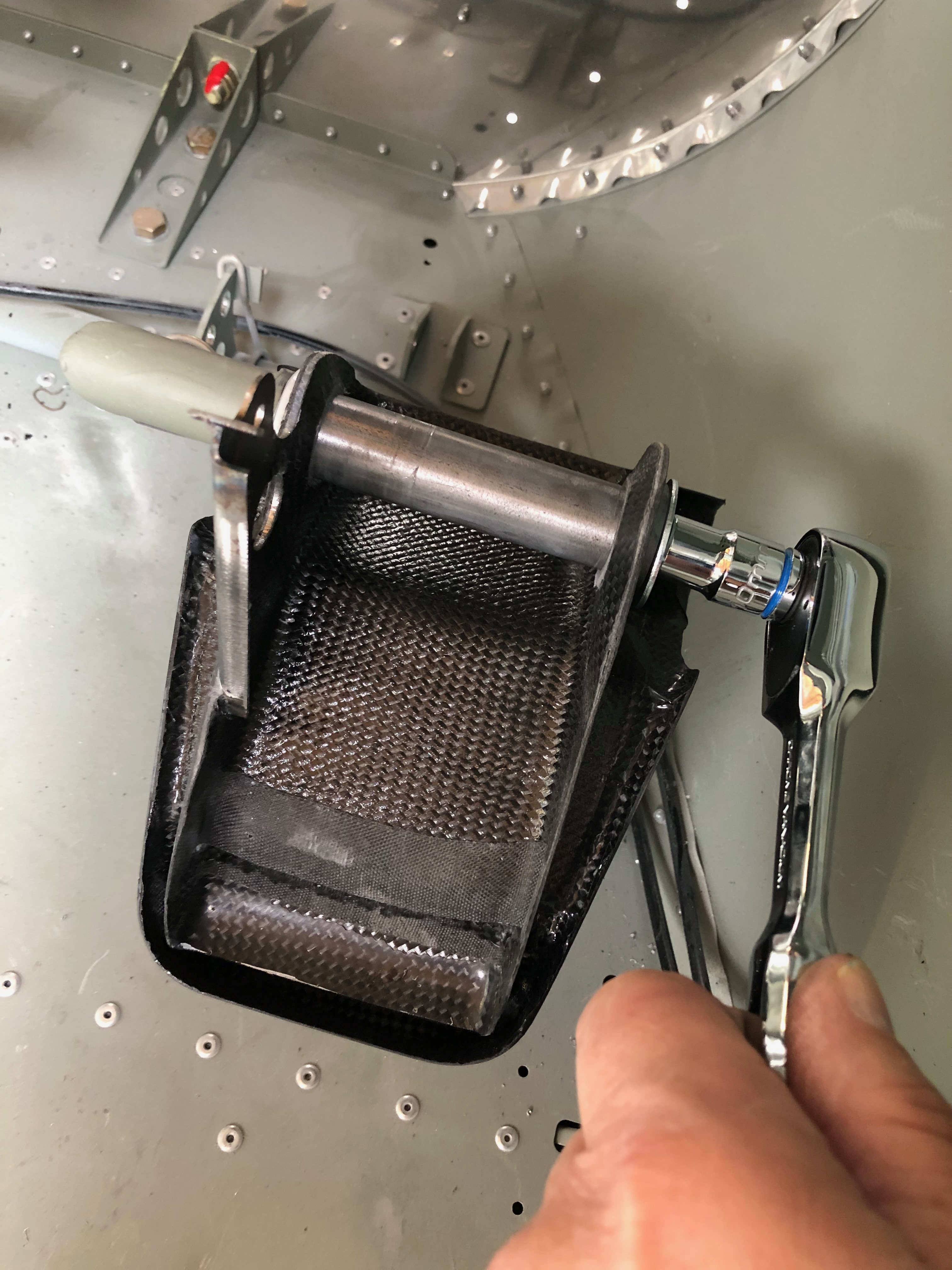
The final job for today was to trim the cowl to ensure is doesn’t come into contact withe the water radiator.
Finishing off the panel modification today and the start of the landing lights.
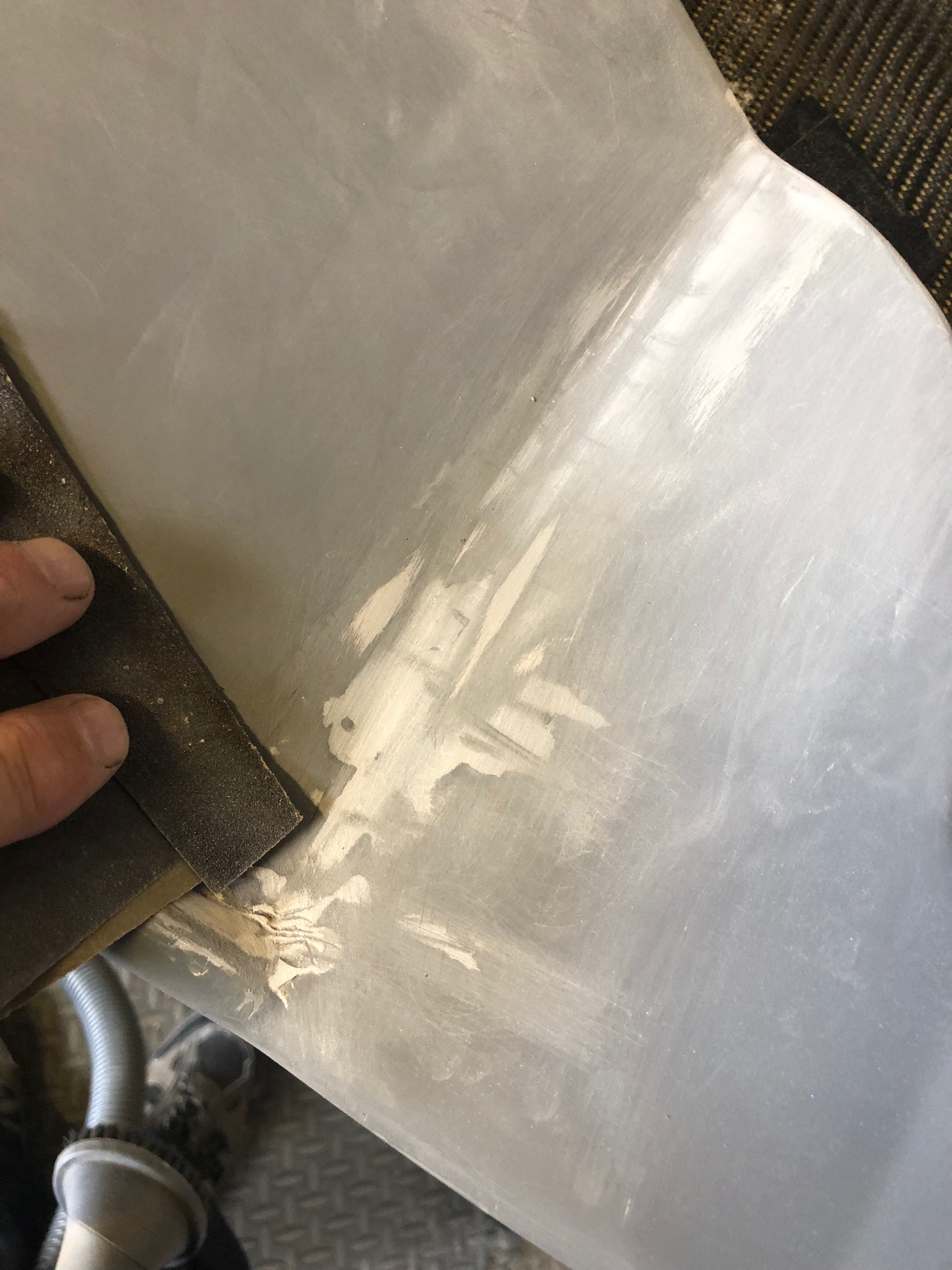
There were a couple of areas where I needed to use filler and then sand with fine wet & dry.
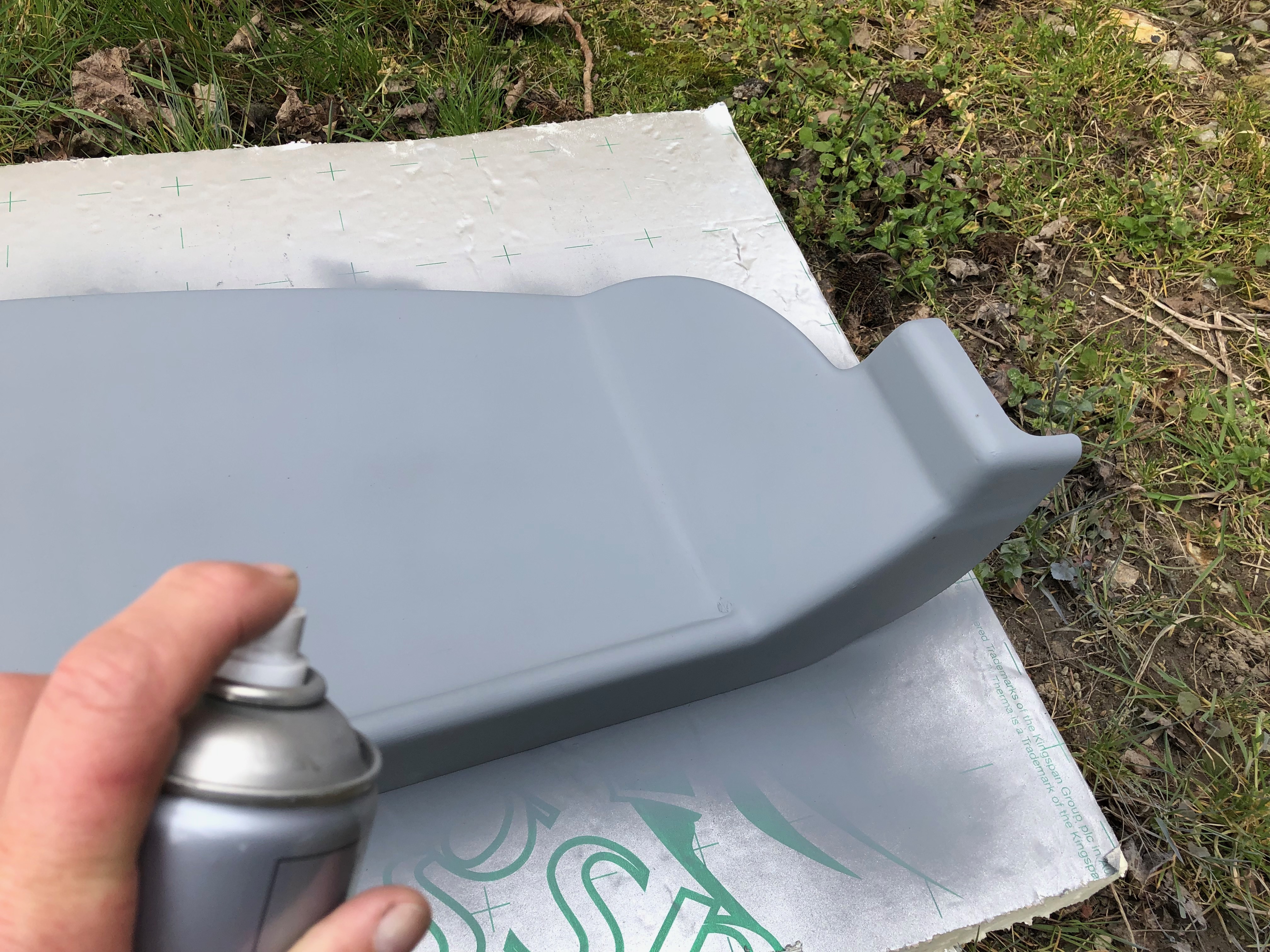
Primer is applied and is ready for painting.
Ian was back today after a few days away and gave me a hand to get a wing up on the stands so I can install the landing lights, wire the trim motor and fit the strobes.
The LED units are installed in both wings.
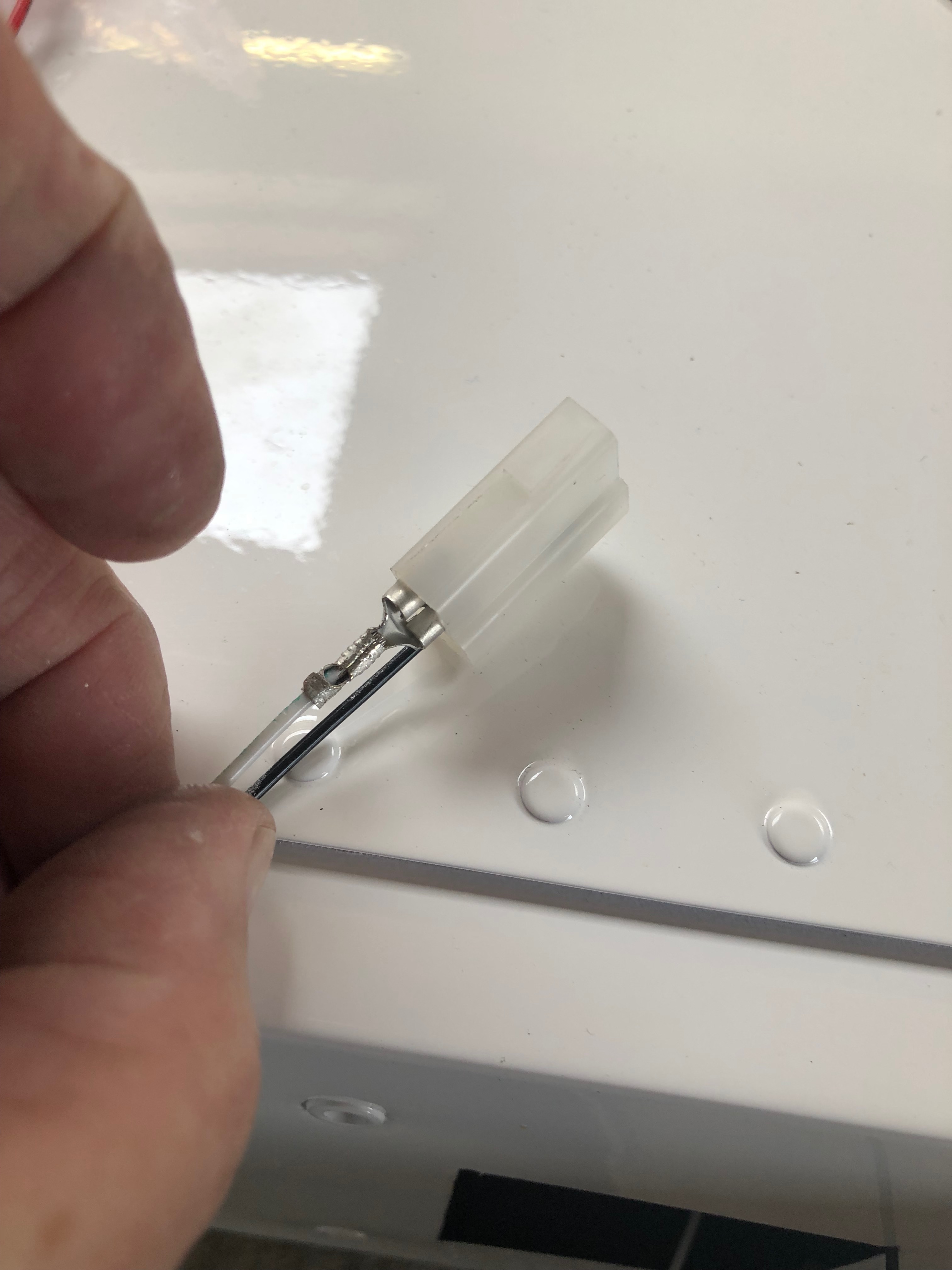
The wires are shortened and connectors are crimped and inserted into the connector block.
The unit is secured into place with M4 screws and then checked to ensure they work!
The light cover is secured into position with tape…
and six holes for the M4 countersunk rivnuts are drilled…
and countersunk. The rivnuts are then installed…
and the light cover is fitted and secured into place with countersunk stainless steel screws.
The interesting thing about building this aircraft is the number of activities and installations that need to be done that I’ve never done before. It takes a little thought to work out how to approach the task before starting but once completed successfully it gives you a great sense of achievement and satisfaction. The modification of the panel using glass fibre matting and resin is one such job. I knew what I wanted to achieve and now it’s complete I’m really pleased with the result.
This was how I left the panel yesterday. Now fully cured the fibreglass needs to be built up.
The area to be built up is wetted with resin and a layer of glass fibre is added and coated.
Once dried in around 30 minutes the area can be sanded down.
The rear of the panel ready is now complete but the front face needs to be filled with P38.
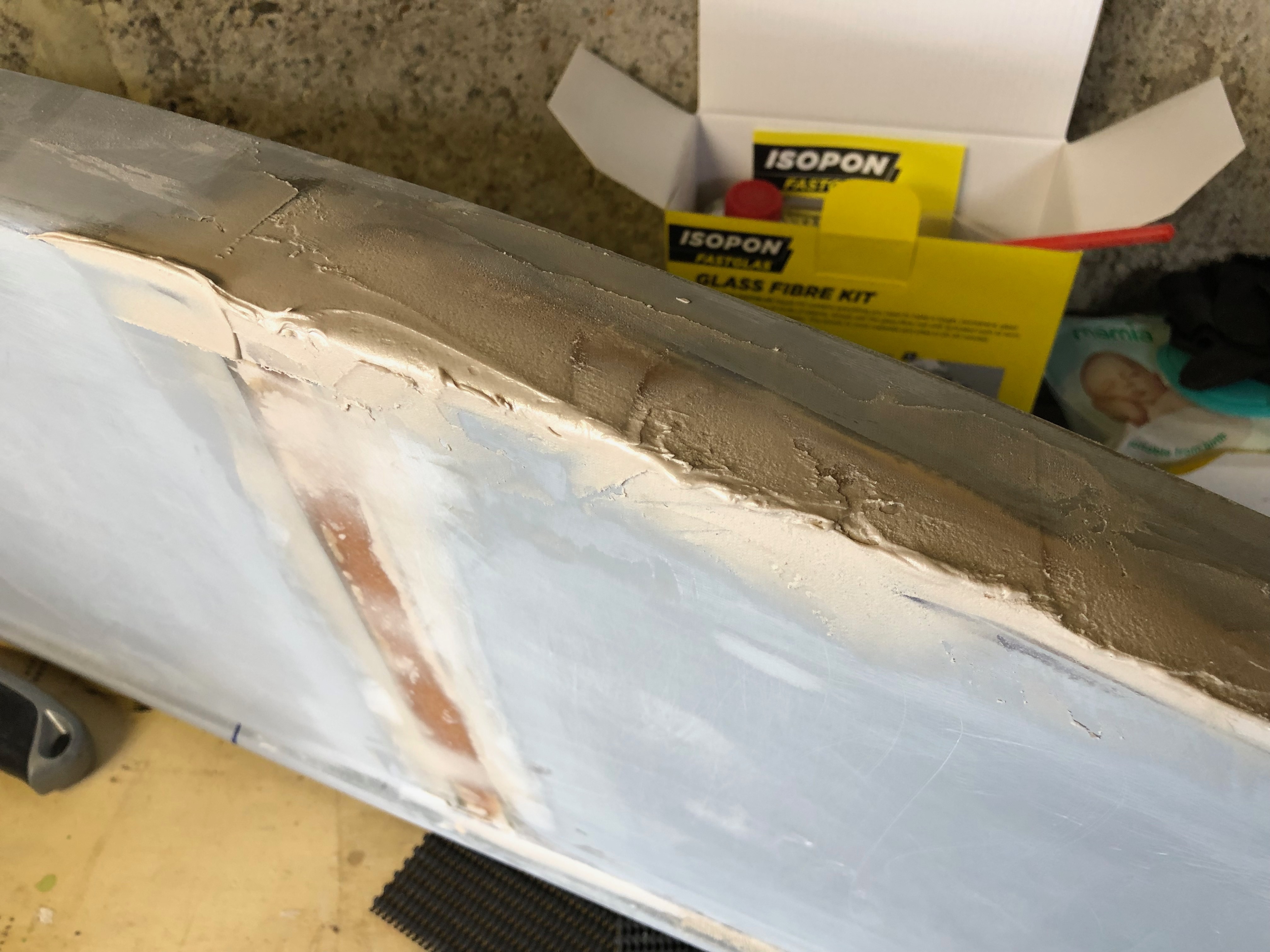
I used an Isopon glass fibre kit to bridge the gap and support the joins and P38 to fill and finish before painting with primer.
The filler is mixed using one golf ball sized ball of resin to one pea sized ball of hardener and mixed within 4 minutes. P38 sets in 20 minutes so you can’t hang around.
The filler is applied using a spatula and sanded smooth using 180 wet and dry. The process is repeated several times to remove any holes or dips.
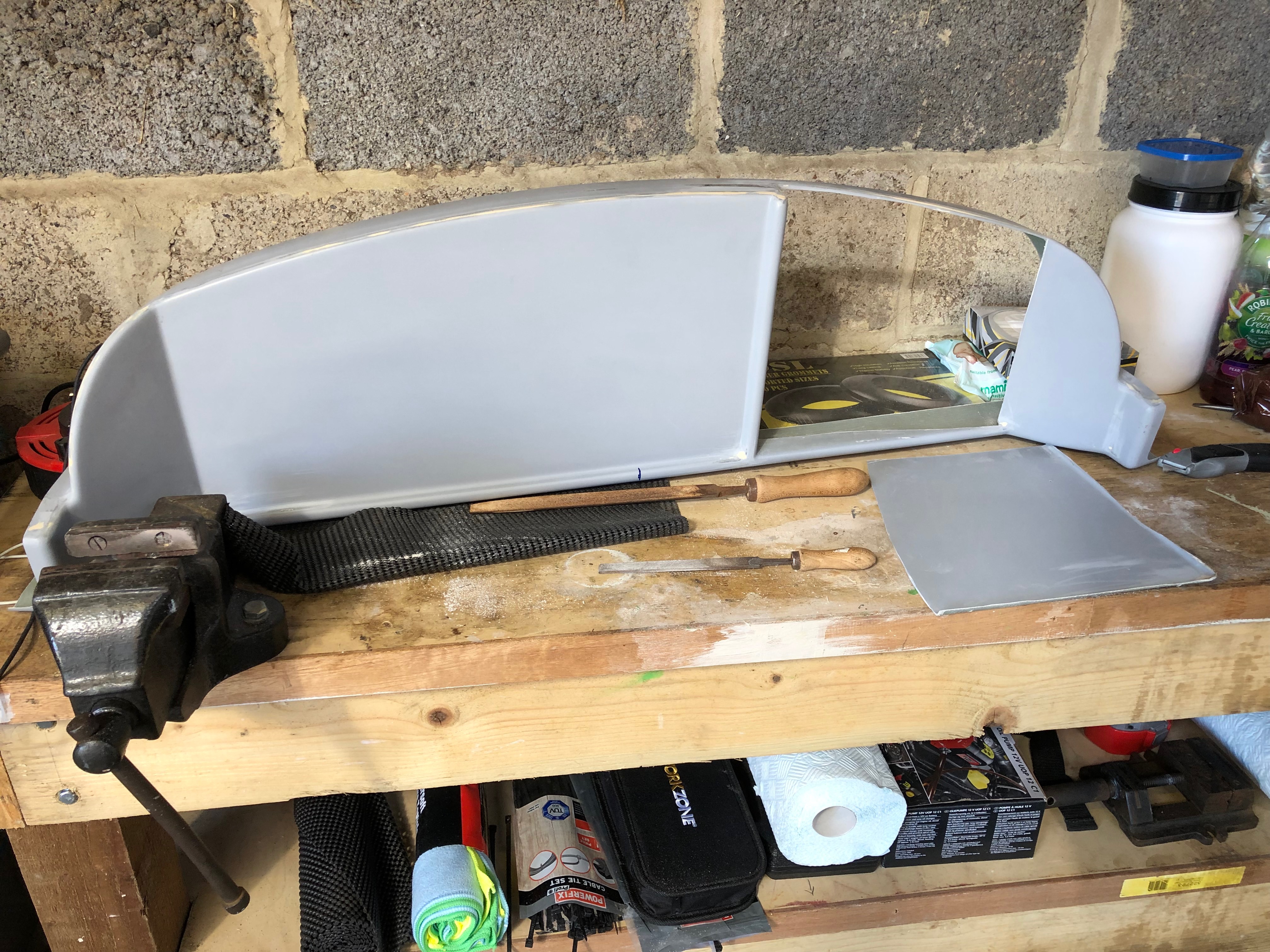
The finished panel prior to painting. Apart from the different colour where the join is you can’t tell that it’s been modified. Very pleased with the result!
The panel supplied with the Bristell kit has a recess on the righthand side that is slightly angled towards the pilot. Although it could be useful it restricts the flexibility of the instrument layout. I decided very early on that I would cut the recess out and make the panel flat.
The rear of the panel showing the recess that will be removed.
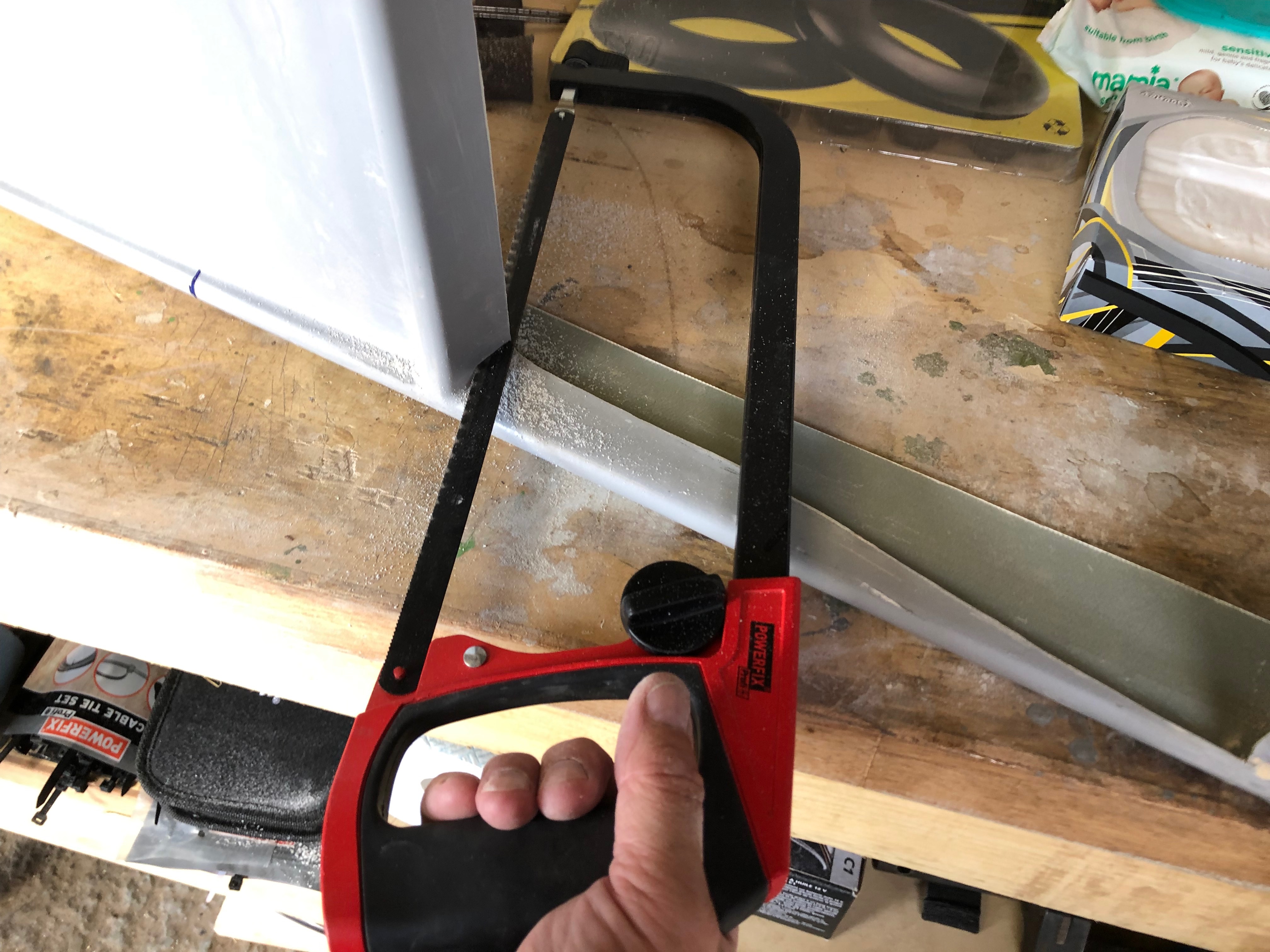
I bought a rotary cutting tool from Lidl that has proved to be very useful for this type of job as you can easily get a saw into the tight spaces.
Once the recess is cut out the edges are cleaned up with a file.
The panel with the recess cut out…
Once the vertical bar is removed the panel can be readied for the fibreglass.
The panel that was cut out can be reused to fill the void but will need to be secure in place to make sure that it’s in line with the rest of the panel.
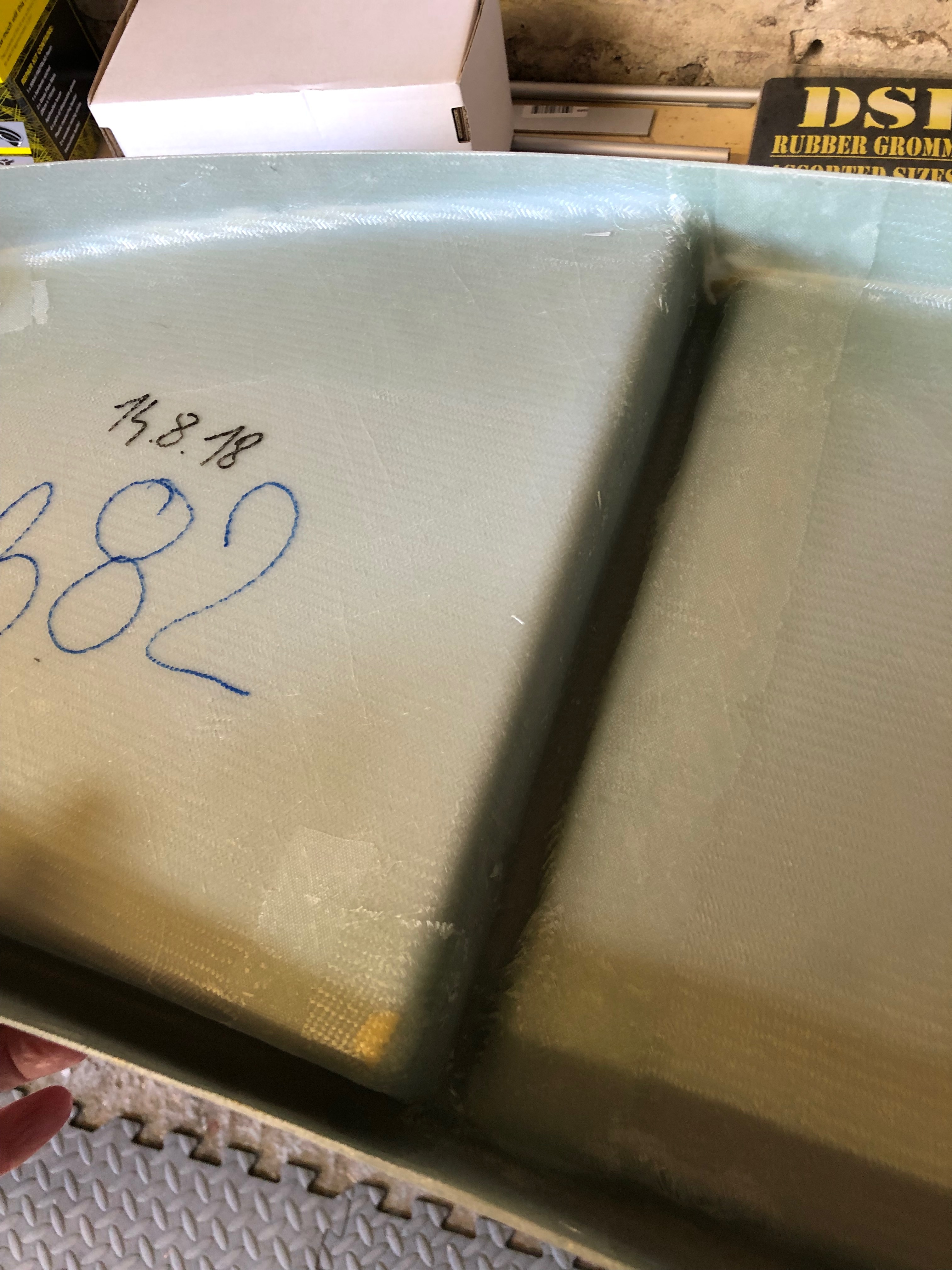
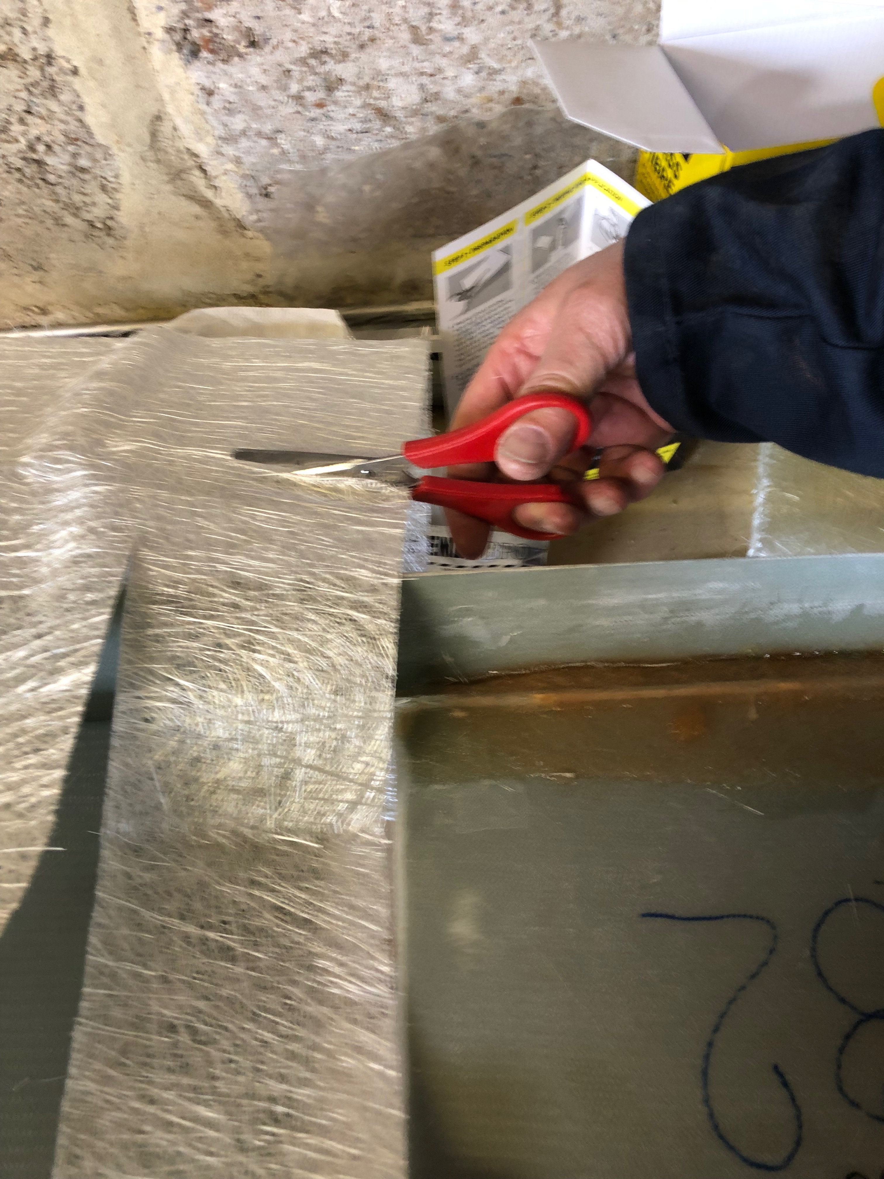
The fibreglass is cut to cover the sections that need to be filled.
The resin is made up from 10ml of resin to 1 pea sized portion of hardener.
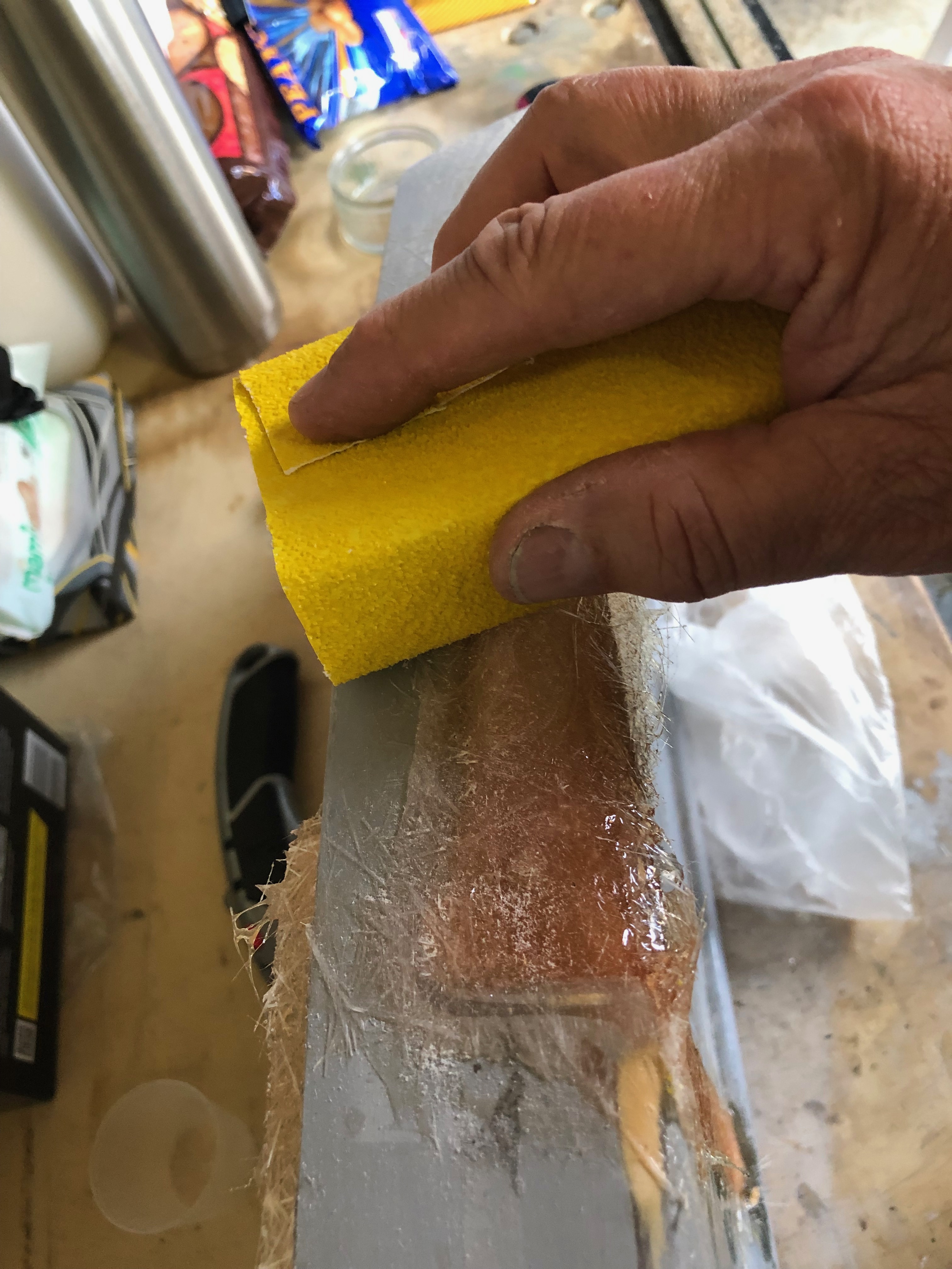
The area that will be covered with fibreglass is ‘wetted’ with resin first to make sure that it will stick.
The fibreglass is laid on the area and the resin is dabbed on to fully wet it.
The fibreglass area after it’s been fully soaked with resin. It takes about 30 mins to set. Once fully set other layers can be laid up or the area can be sanded.
Some of the stiffness of the panel may have been lost by removing vertical bar so some strengthening may need to be introduced once the panel is cut to take the instruments.
As I’ve now ordered the avionics for the build I thought I’d make a mock up of the panel and see what it looks like in the plane.
One of the jobs left over from the fuel system install was to fit a 1/8″ NPT blanking plug in the top of the gascolator. Luckily Ian Daniels had one spare. Loctite 577 was applied before tightening.
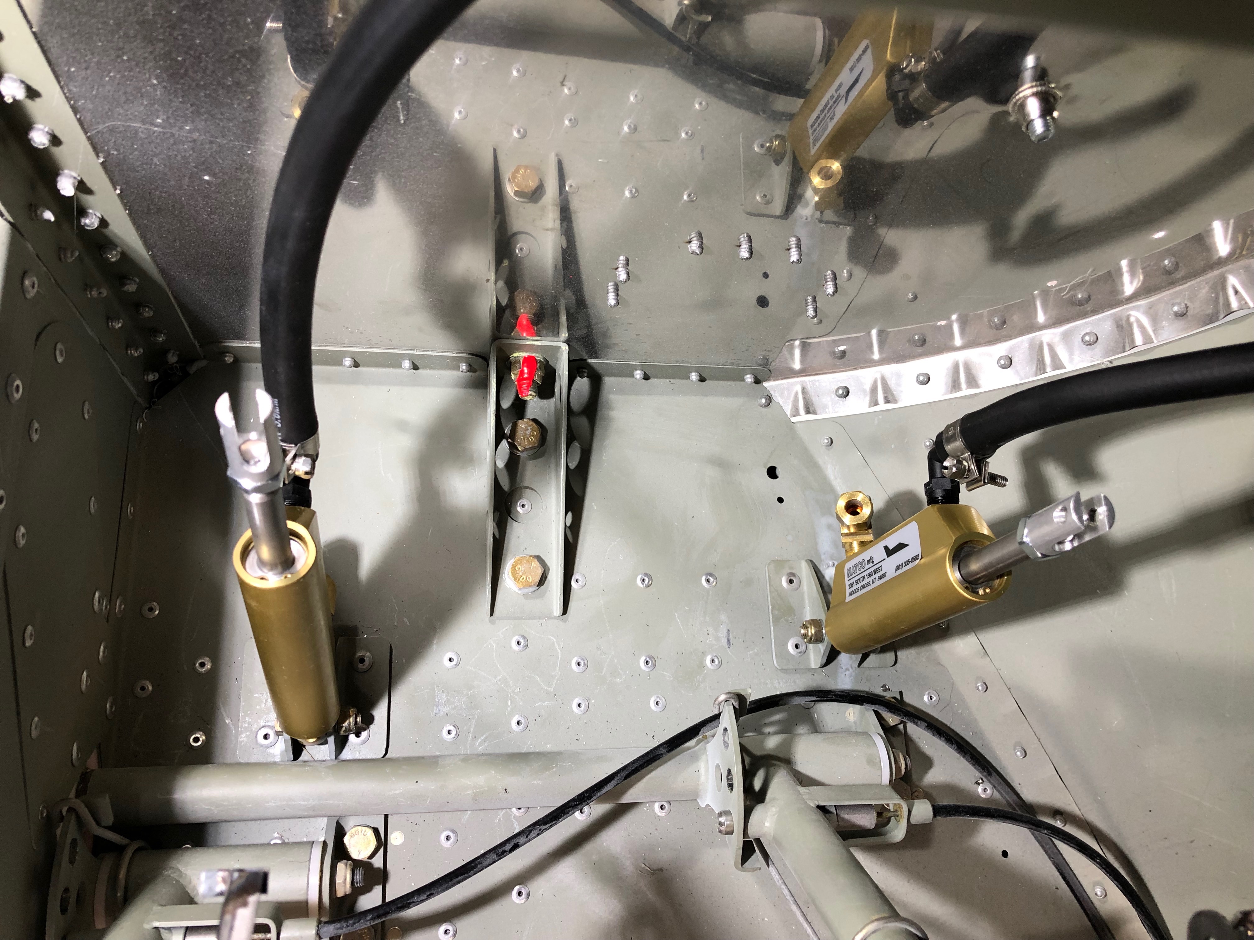
Next up was to start the install of the brake system. The picture shows the components that make up the system. I ordered hydraulic brakes with the parking brake option.
The brake sub assembly is made up outside the plane as it’s quite difficult to work in the front of the fuselage in the space behind the pedals.
The master cylinder fittings are added and threads sealed with Loctite 577.
The brake pipes are cut to size and added to the fittings to test the assembly looks right.
The brake pedals are added and secured with an M6 bolt and 30mm washer secured with Loctite 243.
All four rudder pedals in place.
The master cylinders are fitted next using a m3 bolt and nyloc.
The Bristell comes with a fibreglass panel that has a recessed section on the right hand side angled slightly towards the pilot. The problem I found is that with the recess it was impossible to install two Garmin G3X 10.6″ displays.
G-NGII showing the panel and recess on the right
My thought is to remove the recess by cutting it out and then re-glassing the panel to make it flat. To visualise the change I covered the panel in cardboard and white paper and printed life-sized instruments and placed them on the panel.
a) Garmin G3X layout Twin Garmin G3X with GTR225 8.33khz radio, GMC507 Autopilot and Airmaster CSU controller. This panel doesn’t need any backup instruments as the G5 would be adequate.b) Dynon layout Twin 10″ Dynon SkyView HDX screens with Intercom, Radio, Autopilot, common function sub panels and Airmaster CSU controller. Requires more instruments as a backup perhaps a Dynon D6(0)c) Dynon layout Twin 10″ SkyView HDX screens with Intercom, Autopilot, Common function sub panels centrally mounted and an Airmaster CSU controller. Requires backup instruments as above.
Very early stages of design but my preference is c). Both Garmin and Dynon have similar capabilities but the Dynon components look so much neater. Still to be added are the graphics for the switches, fuses, a starter switch and trim position indicators.
Following the build of my Bristell NG5 Kit No. 382 Registration G-MLSY