I decided to visit Air Expo at Booker yesterday but I can honestly say the show was a complete waste of my time. It was raining all day and a lot of the exhibitors had scaled down their stalls and some hadn’t turned up at all! I did buy a Sky Echo II there so I’ll see how that works when I finally get the plane flying.
The aim for today was to continue the wiring and connect a few of the sensors.
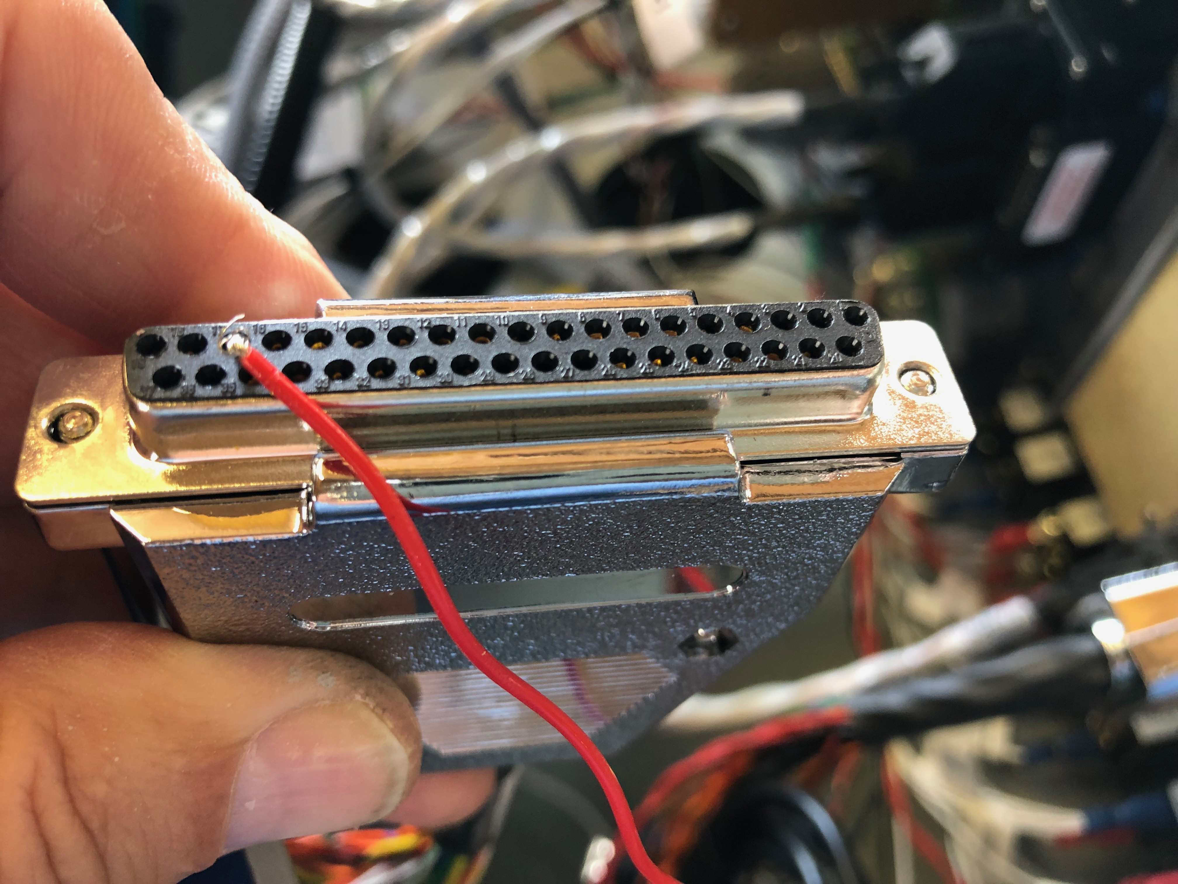
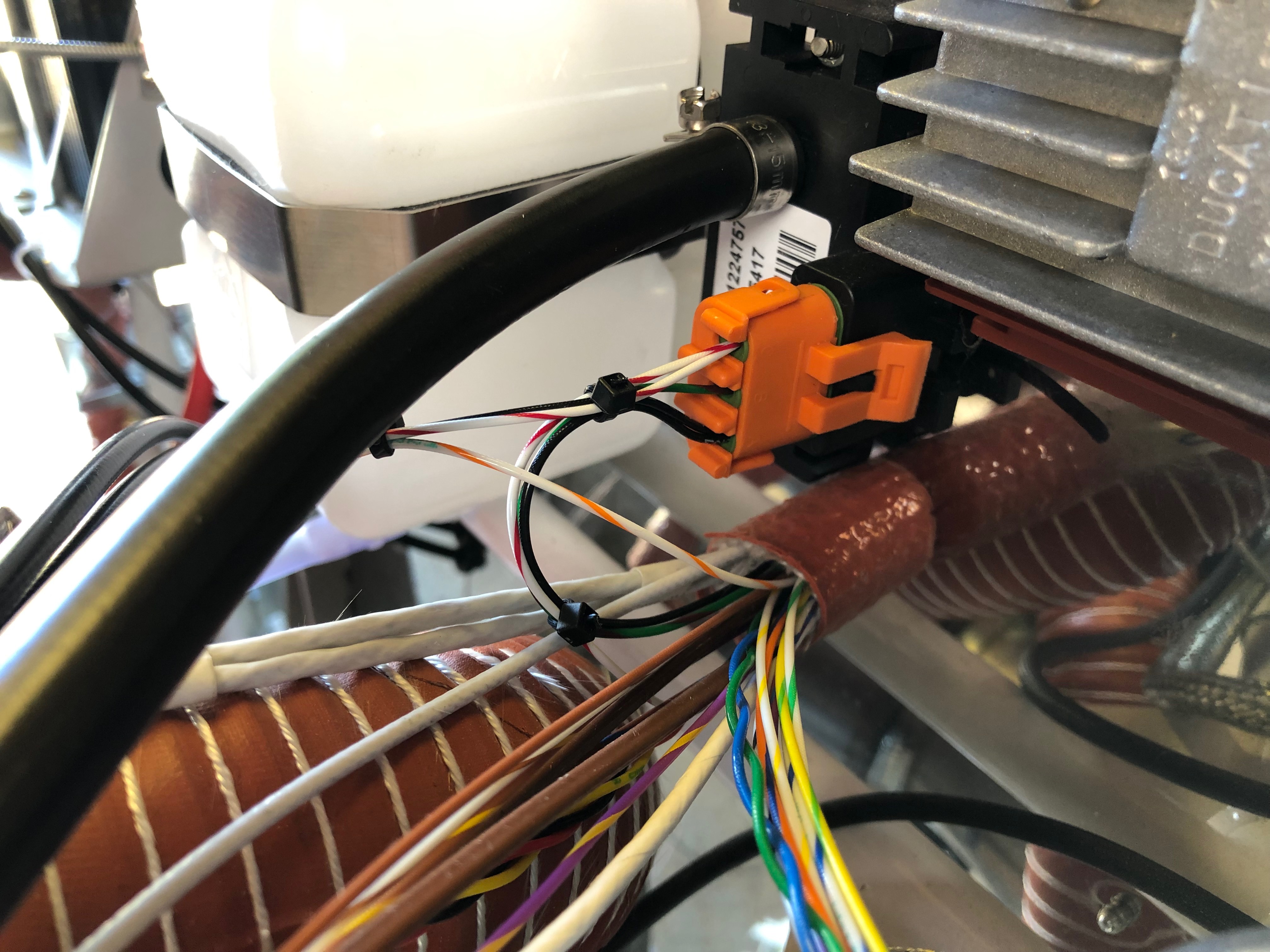
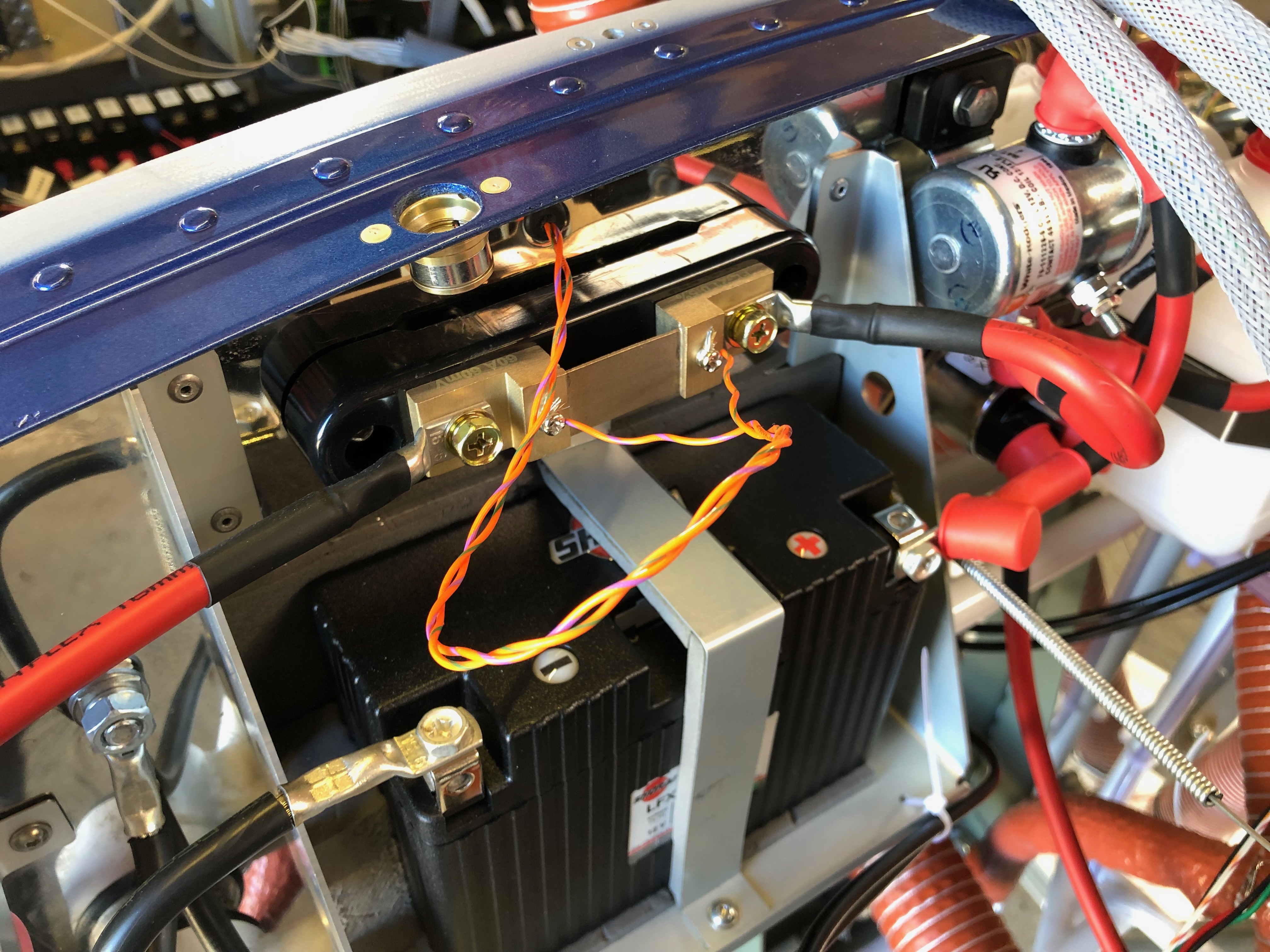
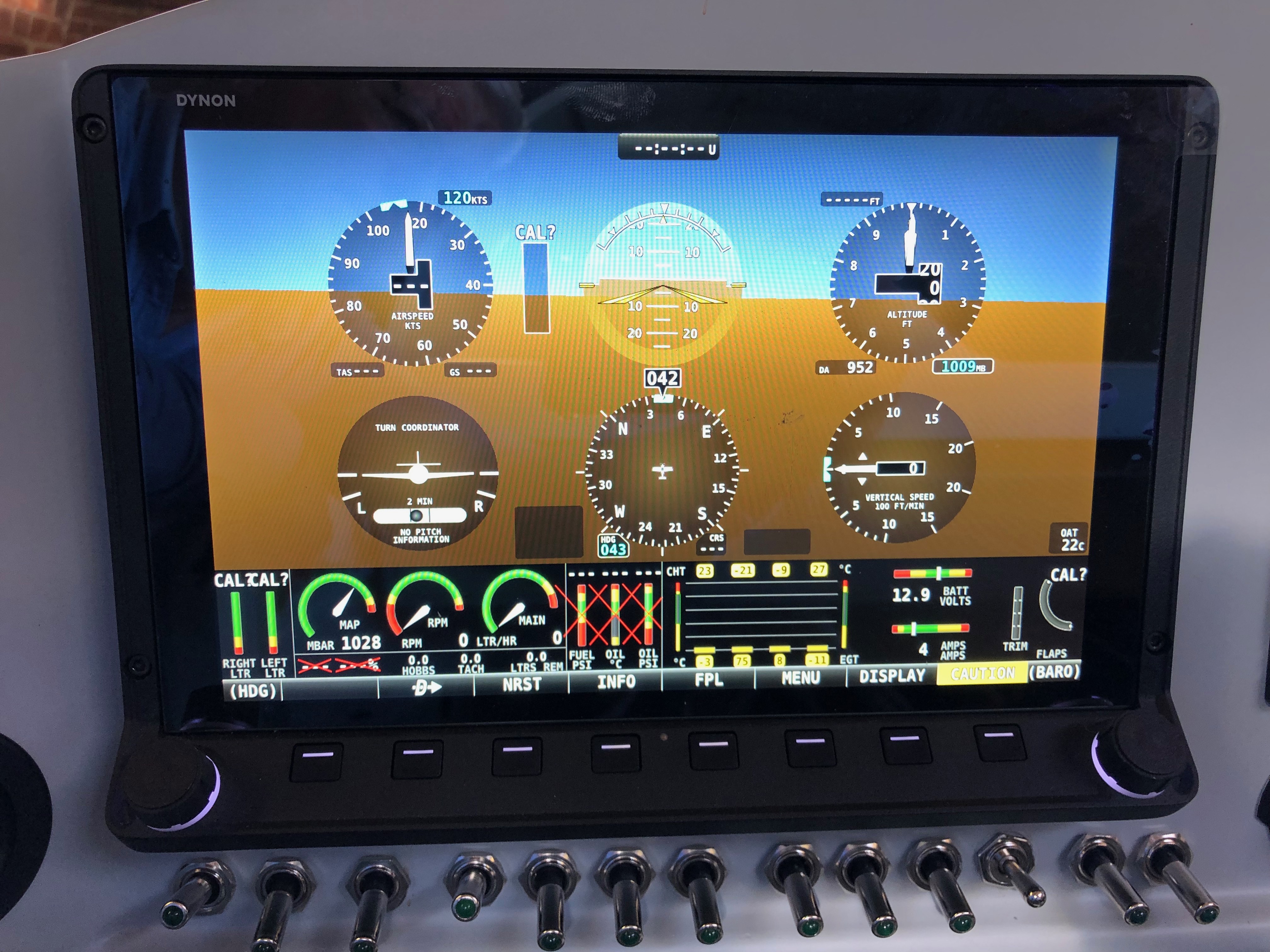
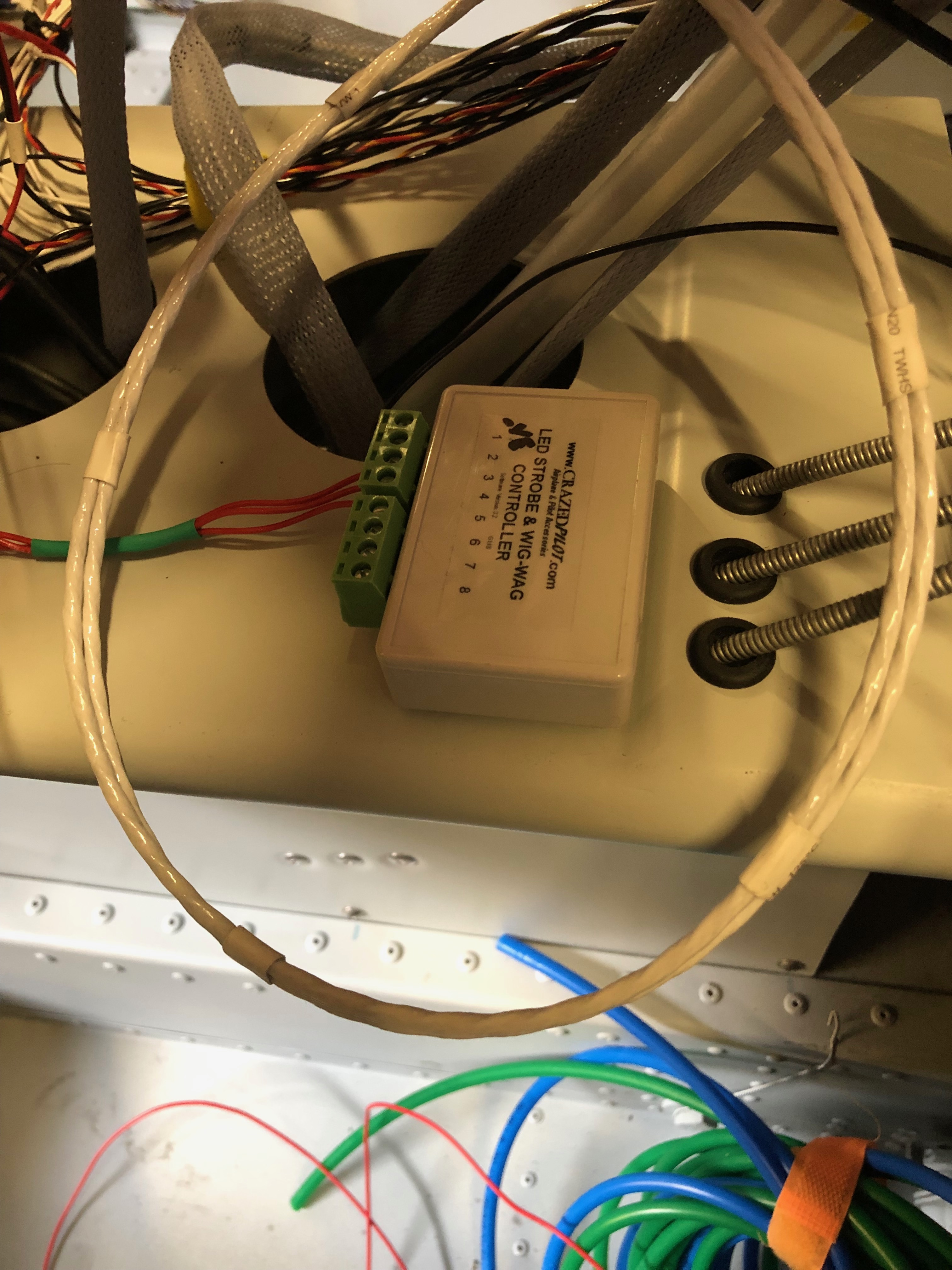
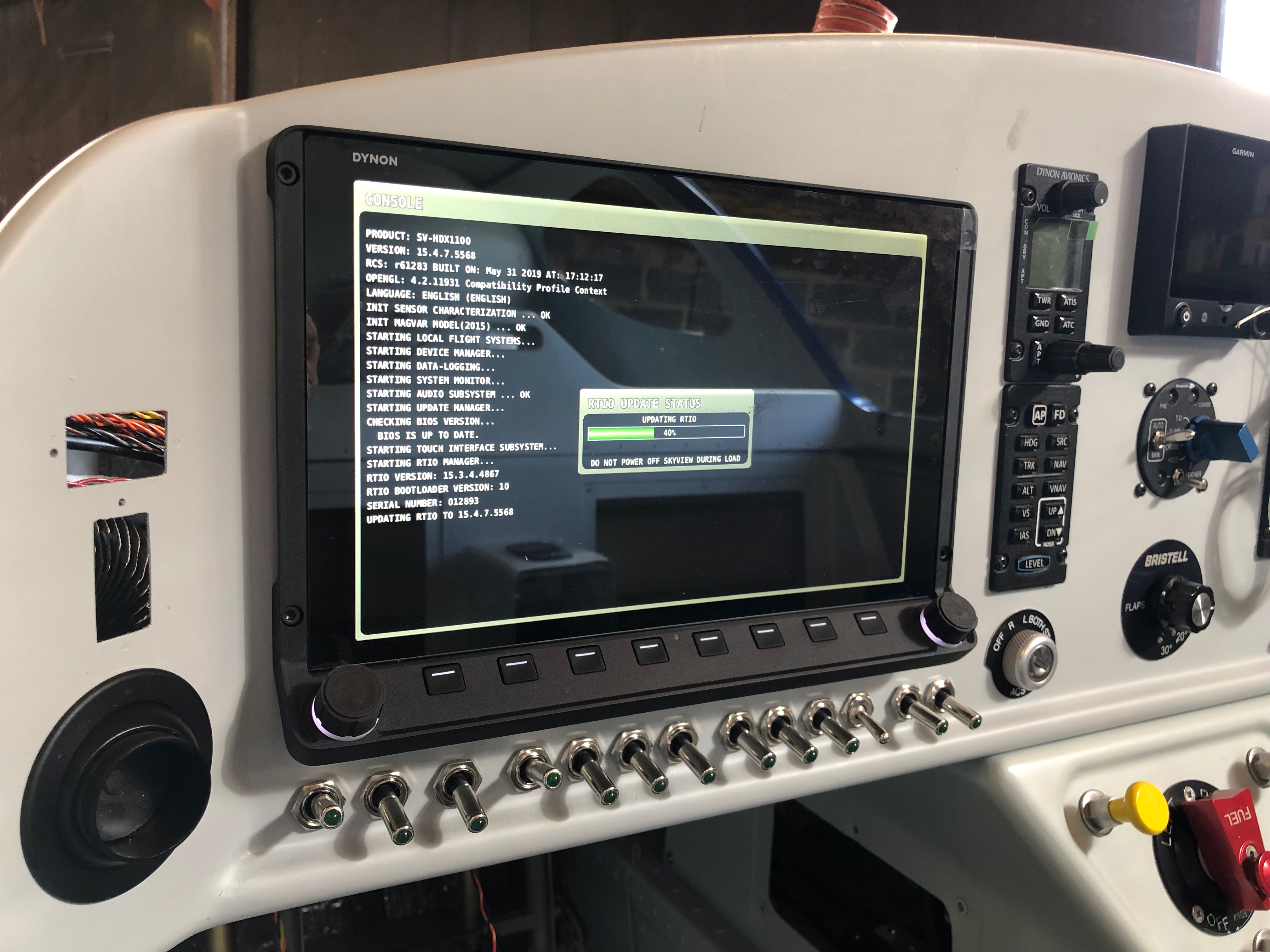
The EMS loom has a D37 that connects to all the various sensors around the aircraft. It’s good to check the pin out with a multimeter before connecting to any of the sensors. First up is the MAP sensor. The power and ground on this sensor can be shared with other sensors so I’ve broken out those pins to use for the the fuel pressure sensor.The system power load can be displayed on the SkyView by measuring the potential difference across a precise resistive load, in this case a Amp shunt. The wires connect to either side of the resister. To protect the SkyView from high currents a 1 amp fuse is connected inline which I’ve ordered and will be arriving Sunday so I’ll fit on Monday.The landing light controller that I bought from the States is wired up to a 3 position switch. I’ve designed the lights to be steady, wig wag and strobe. Hopefully it’ll work as designed.To get the light functions I need a 3 pole and 2 pole switch.The fuel pressure sensor is next but will be done on Monday now as I’ve run out of time.The HDX displaying in s ‘6 pack’ mode but you can see some of the sensors working correctly including the MAP, voltmeter and ammeter readings.
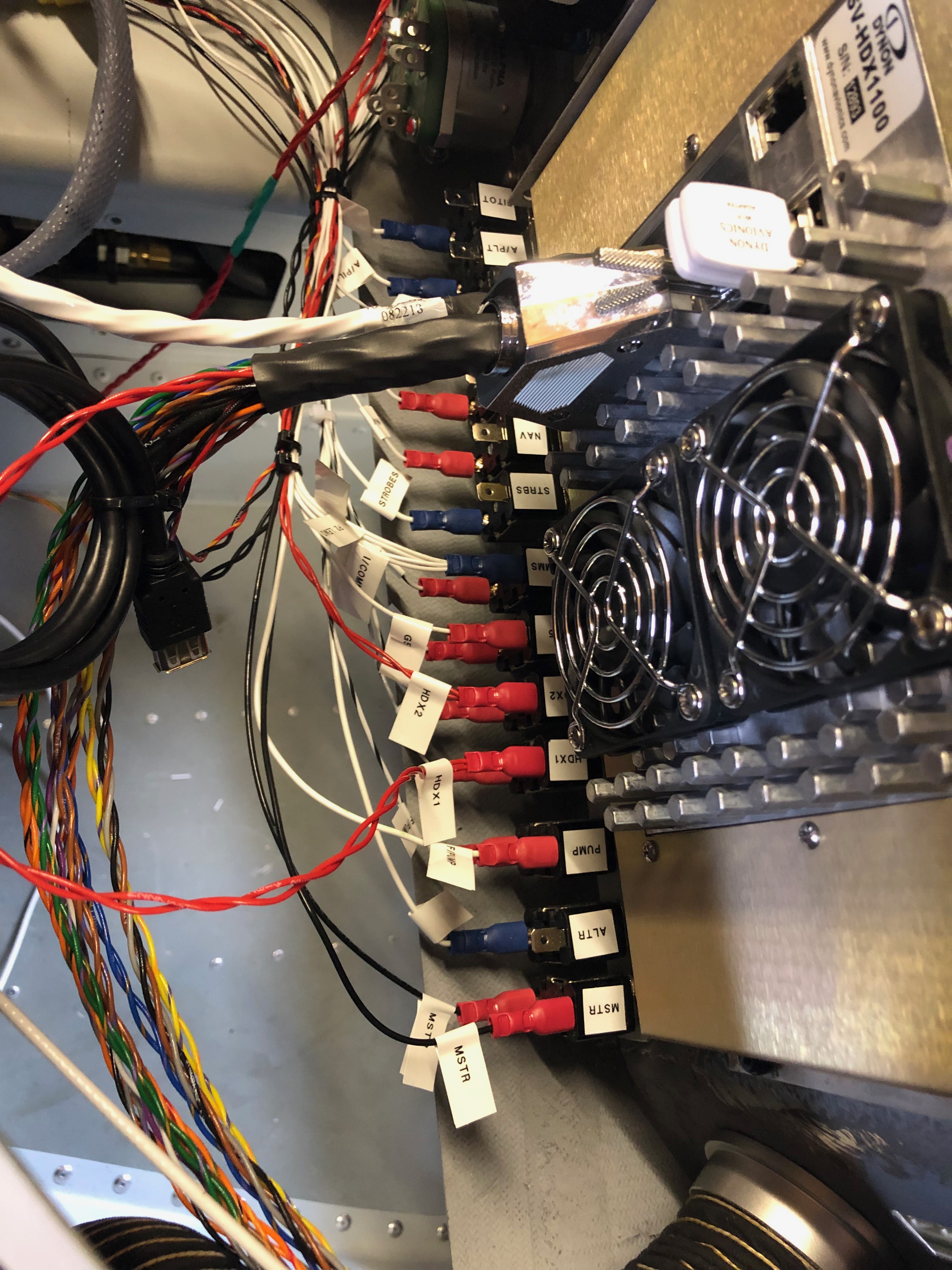
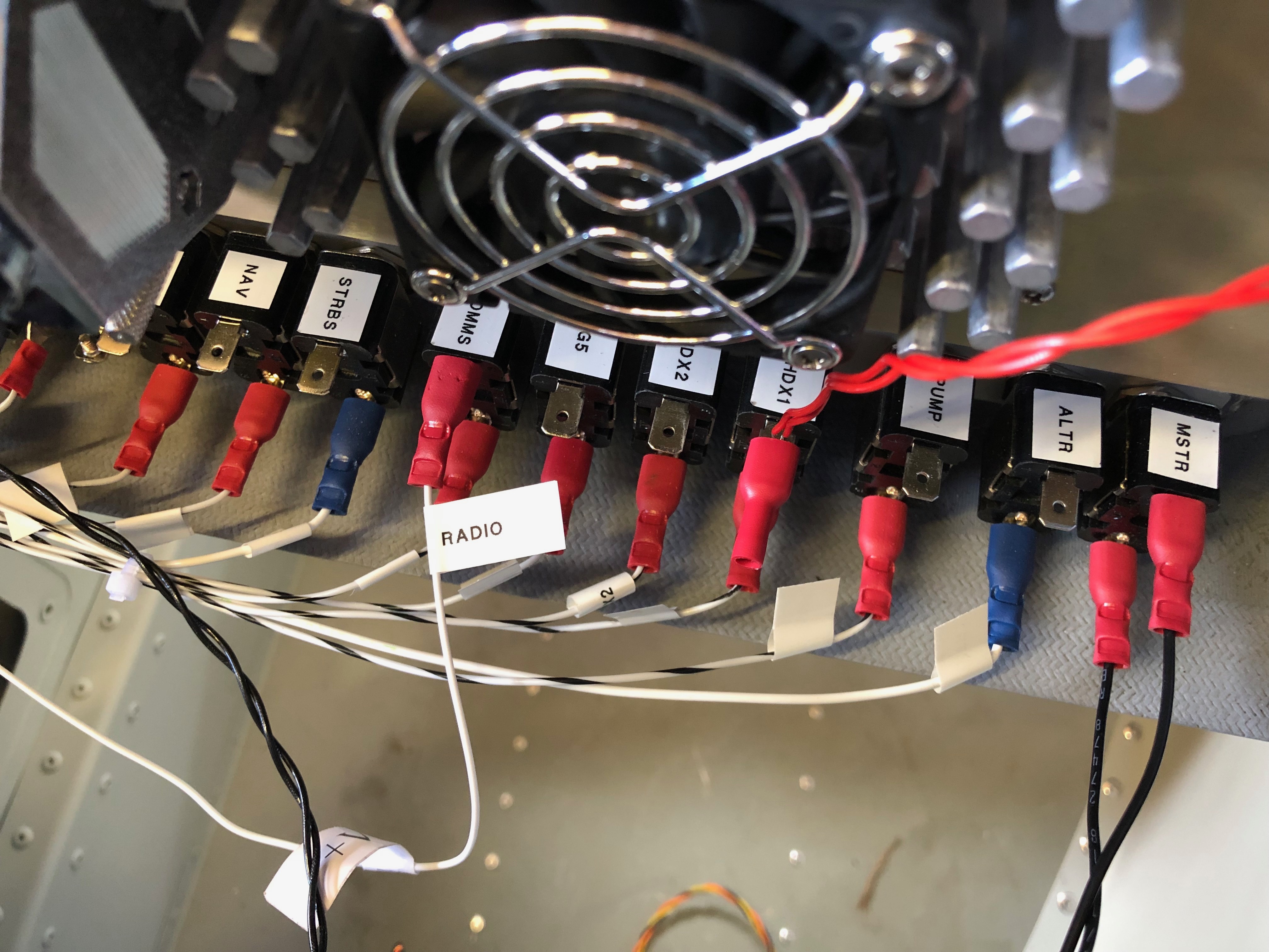
Work continues on the wiring today (and no doubt for a few days more but got quite a lot done today having completed the Master, Fuel Pump, HDX 1, & 2, G5 and Radio circuits.
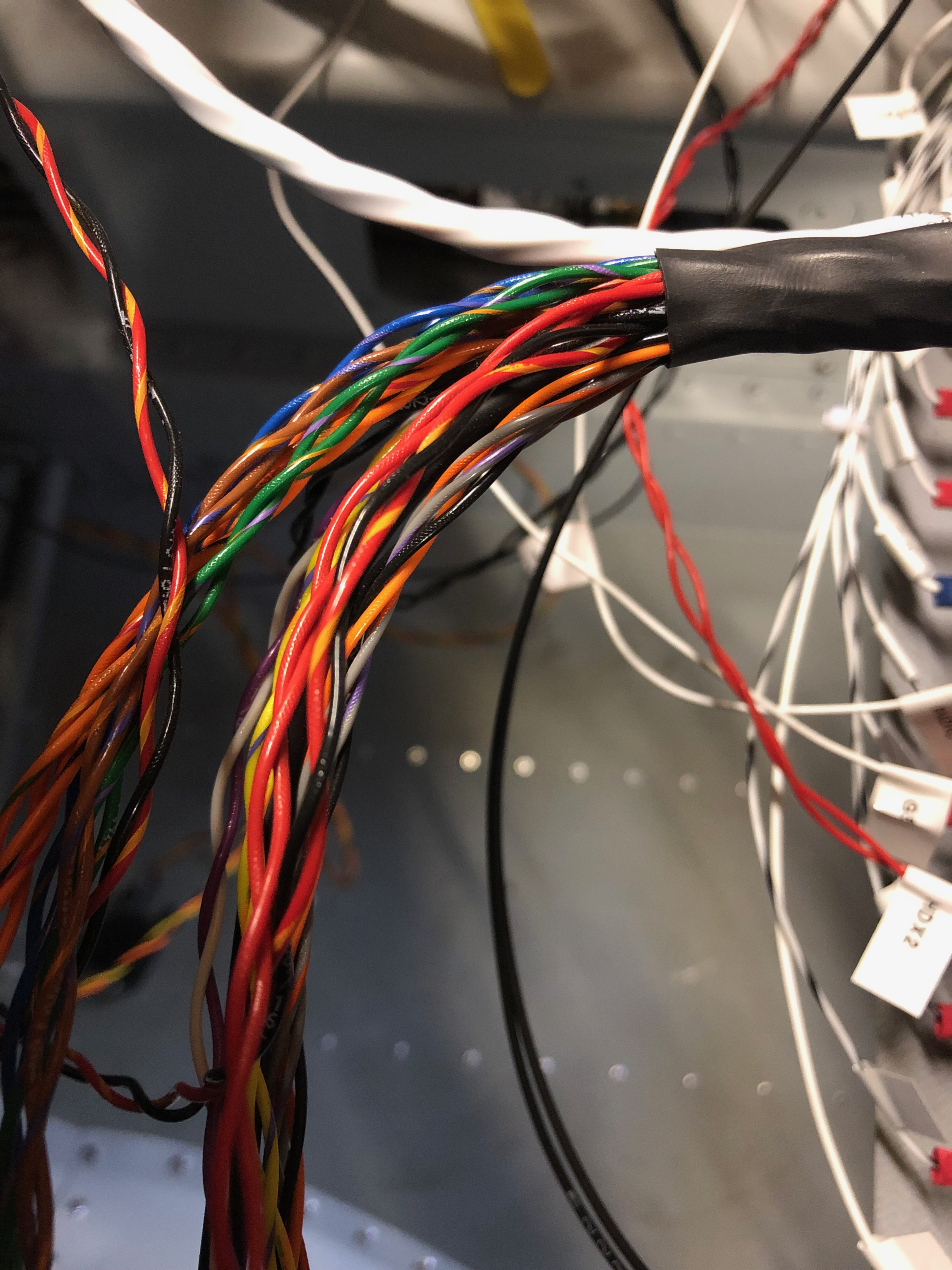
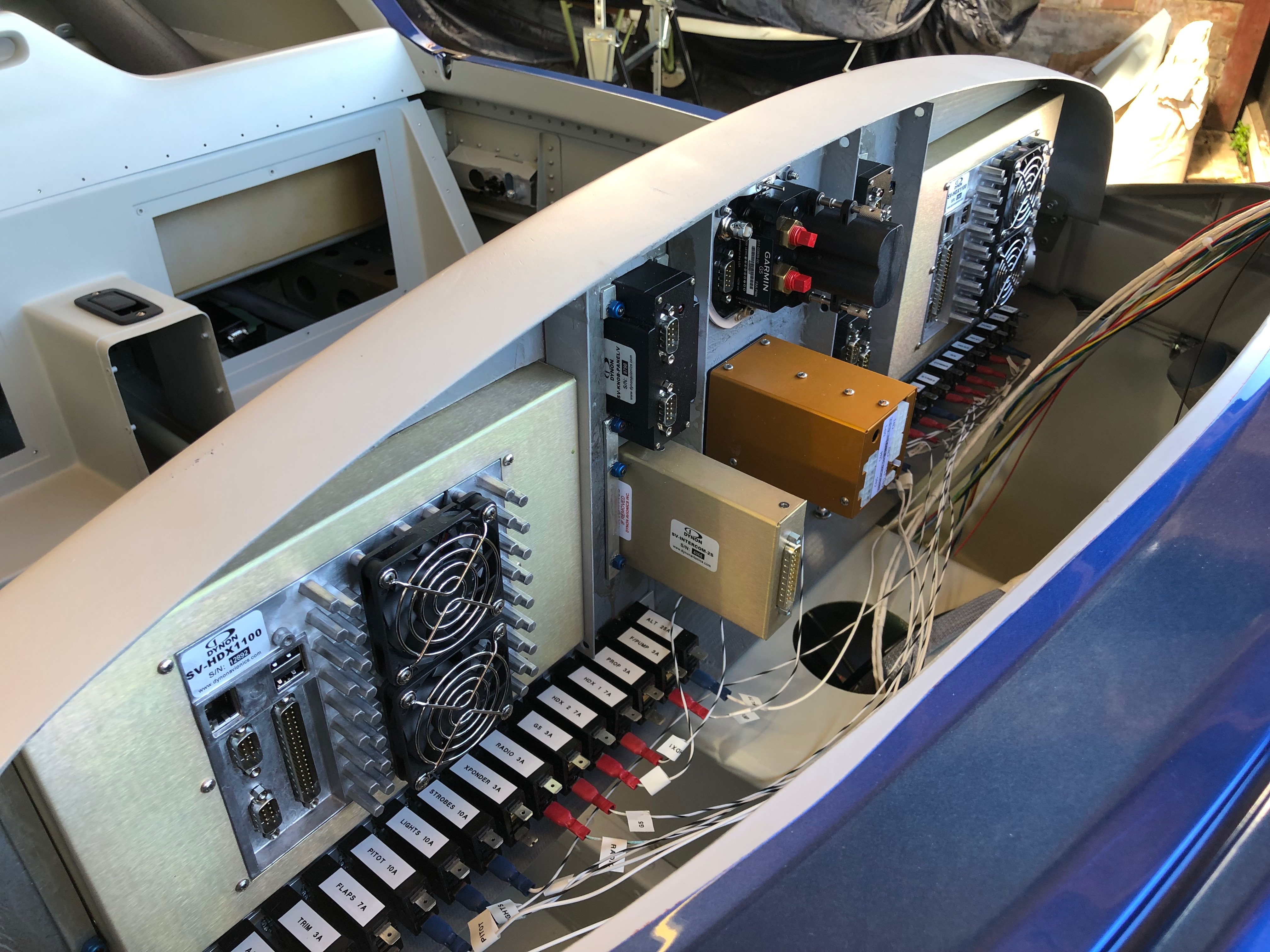
This is the loom for just one of the SkyView HDX screens. It looks intimidating on first looks but they all do something and you just have to work out where they go!The difficult bit was designing the electrical circuit to power all the devices. As I’d fitted the circuit breakers and switches and fitted the interconnecting wires it makes it quite easy to complete the circuit. It’s getting quite busy…so I’m starting to arrange the wire bundles in an orderly fashion as planned.This is the Wig / Wag controller that I bought from the states to give better visibility whilst flying. It allows the landing lights to be steady, flash alternately or flash like a strobe. Just hope it works as promoted!
It’s time to do the wiring. This is going to be long job as there are wires all over the place! There are some things that must be done to make sure that it’s maintainable in the future like labelling as it’s easy to lose track of where wires are going from and to and obviously it’s got to look neat and tidy. First thing is to look at suitable routings for the bundles and make sure they make ‘sense’ then start laying them out. This is one of those jobs that you just have to keep going at and eventually it’s finished!
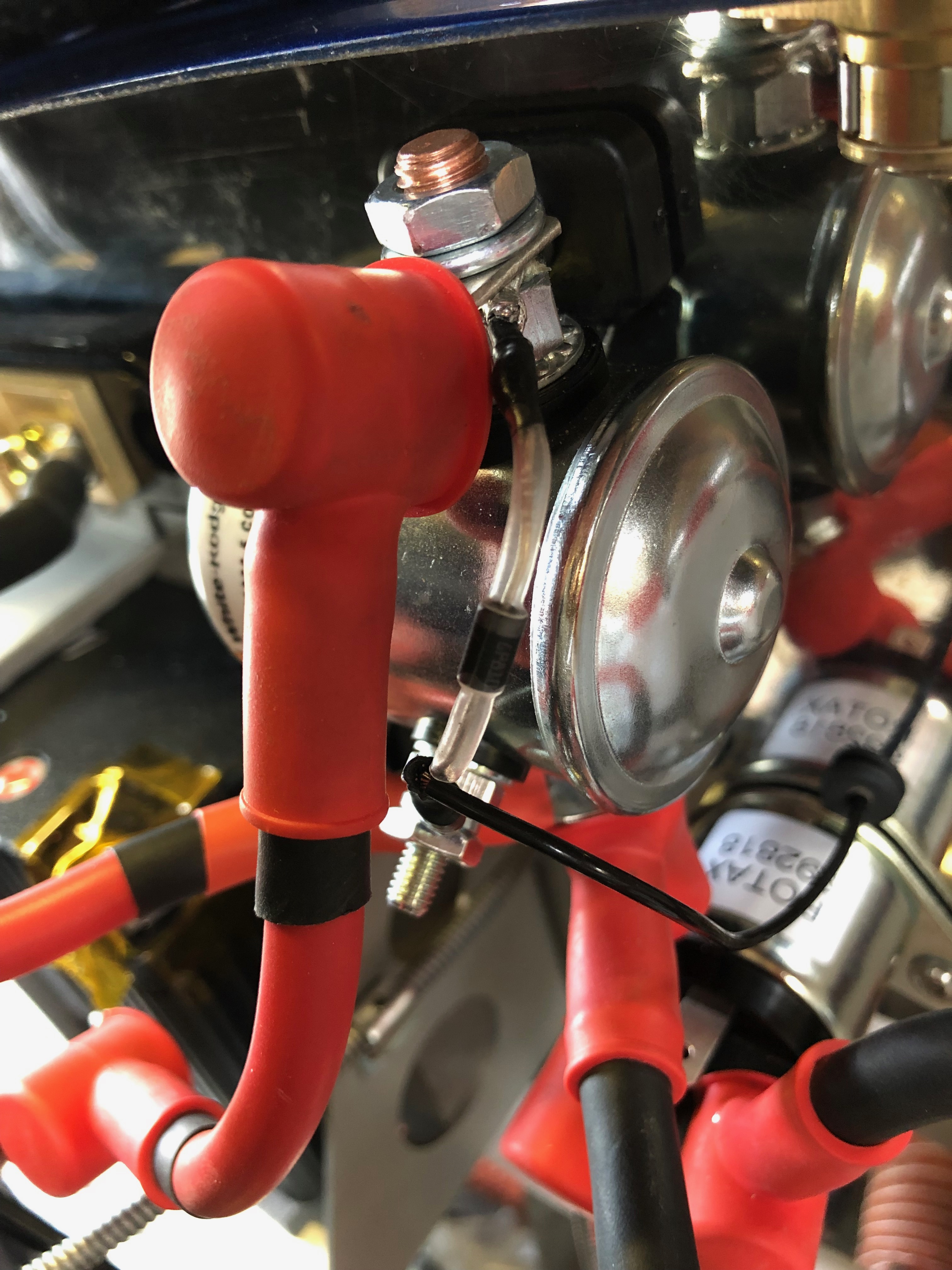
First up is to protect from reverse currents when the master switch is turned off. This is accomplished by placing a diode across the positive and negative posts on the battery contacter.It looks a quite simple but it gets the job done.One of the easy jobs is to run all the ‘earths’ back to the earthing block. After terminating each wire with a insulated female connector a label is attached to the lead. These are just printed off a electronic dymo babbling machine and seem to be suitable for the job. Once the earth is connected, a quick check of the circuit logic and then I can temporarily power up the circuit.Whilst the screen is powered up on main power I thought I’d update the system software to the latest version. The software has a boot loader that updates all the other attached devices like the autopilot and knob panel.Last job today was to run the G5 to GMU11 loom in and secure in place.
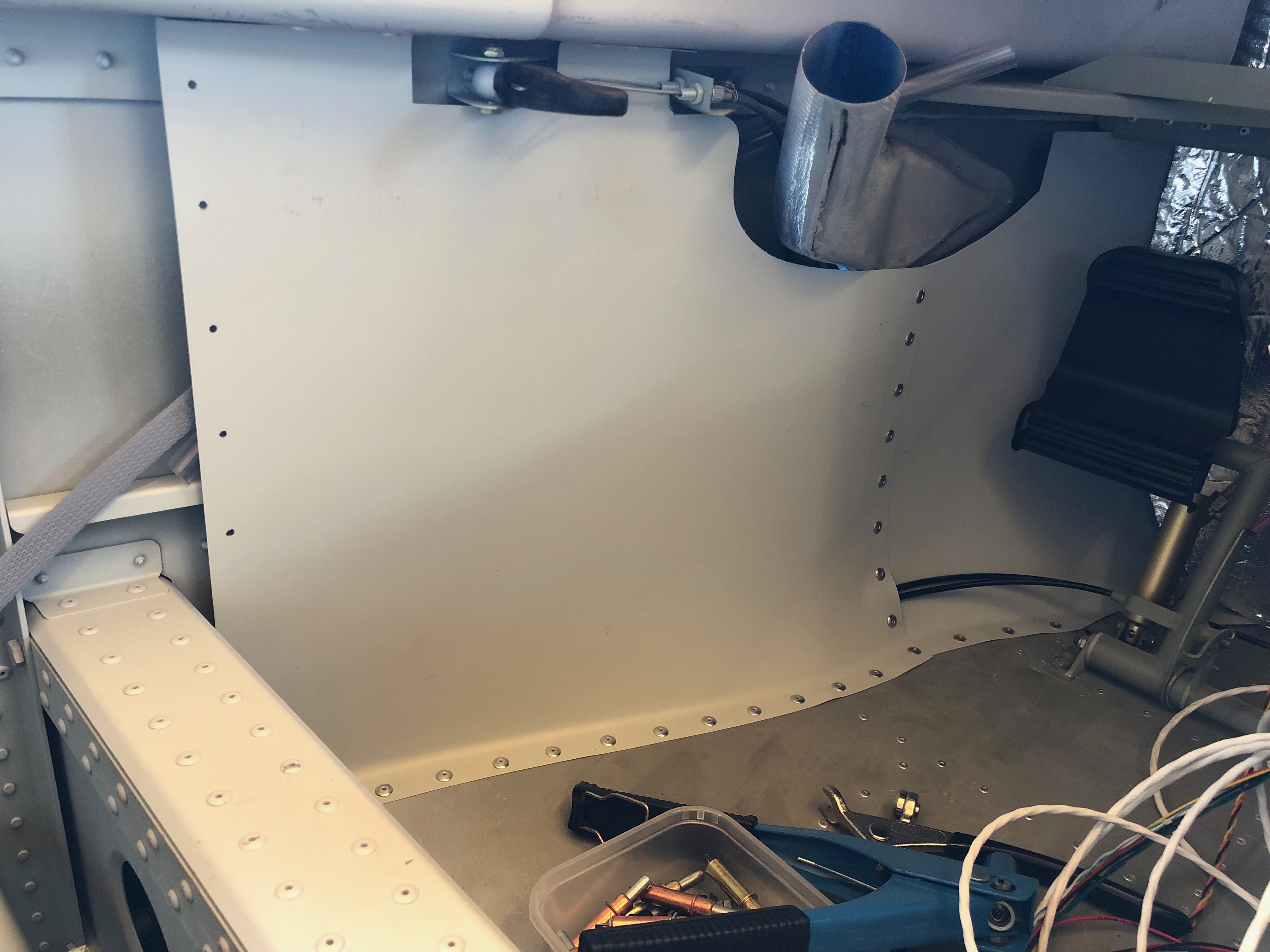
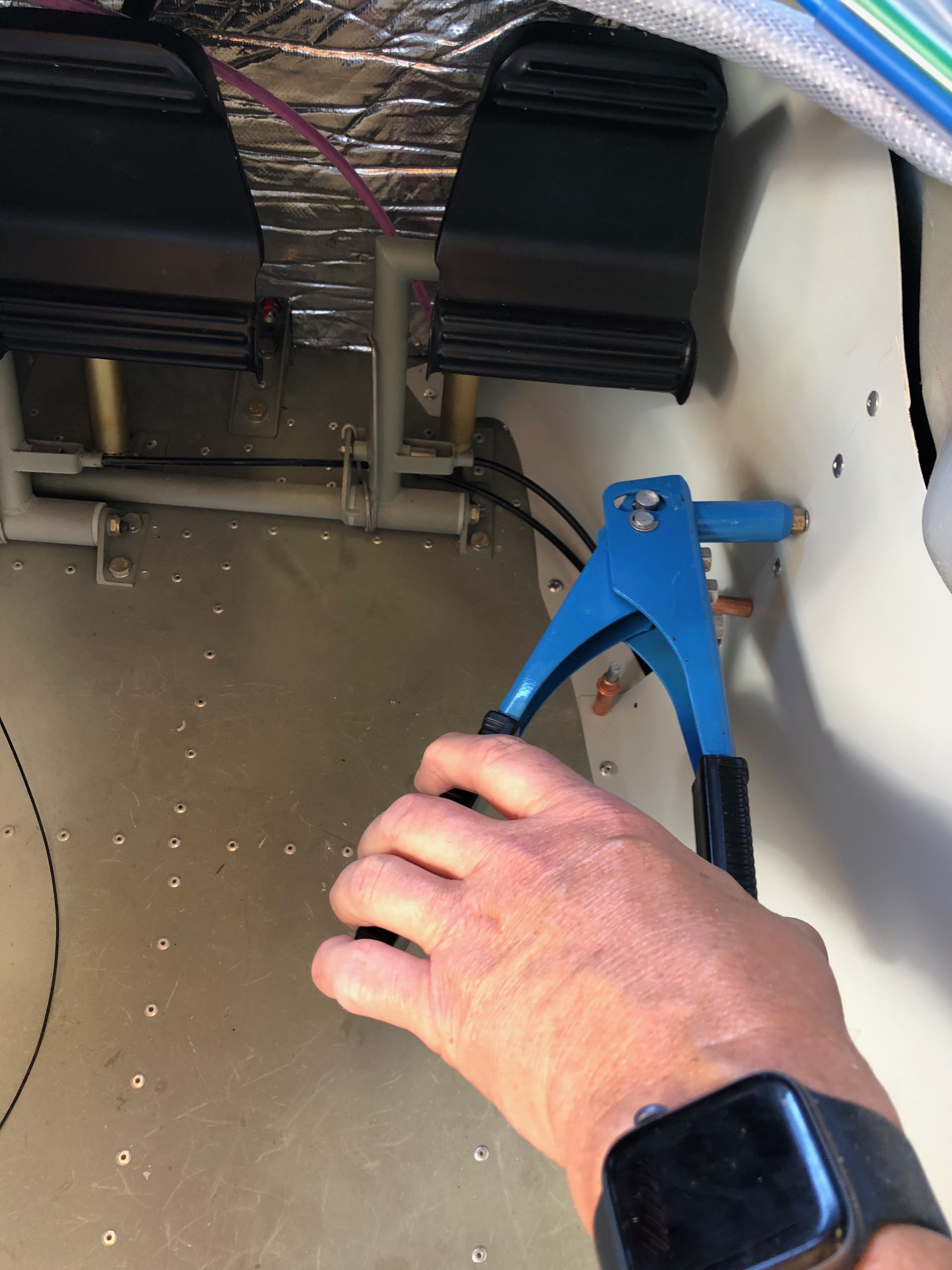
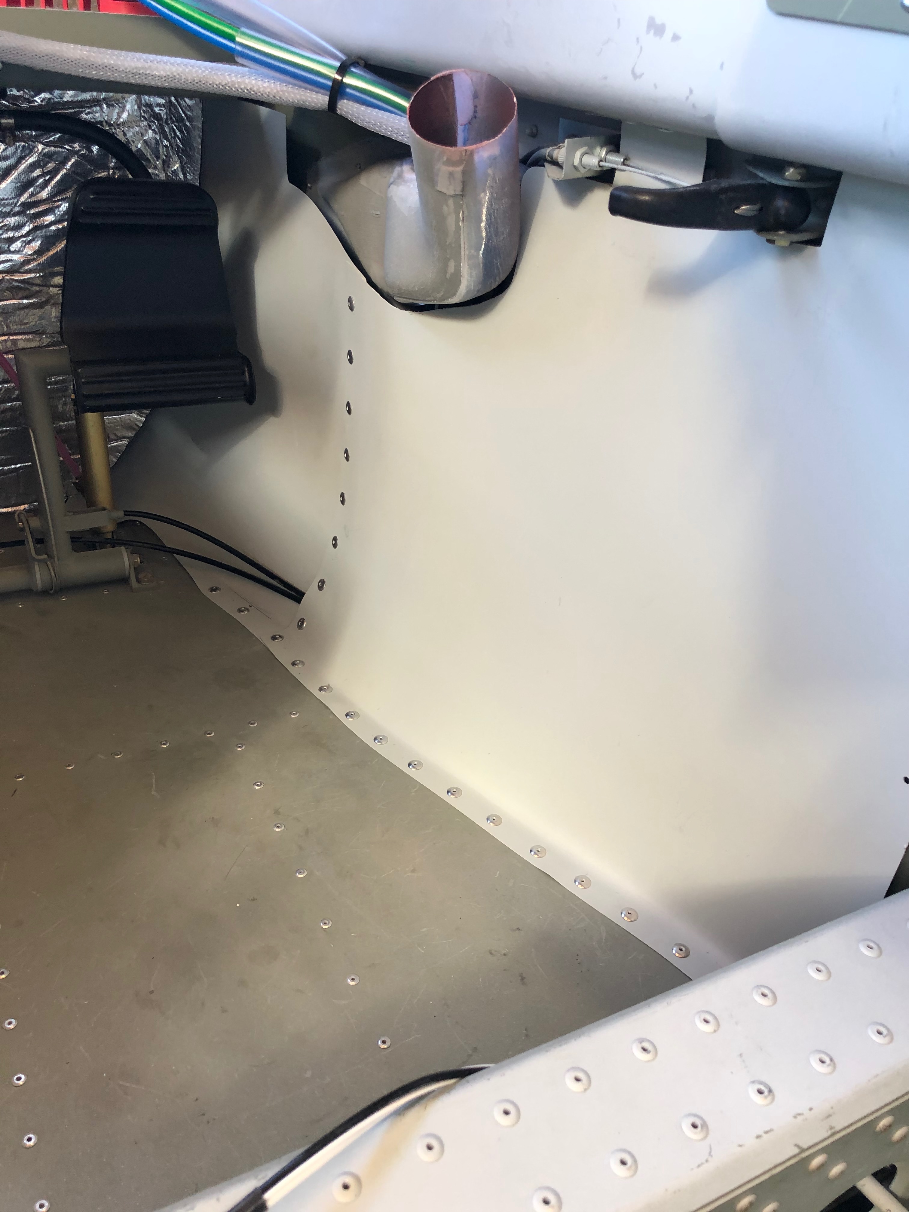
The aim for today was to finish adding the instruments to the panel, install the left and right footwell trims so I can install the instrument panel and get rid of the myriad of associated boxes and packaging!
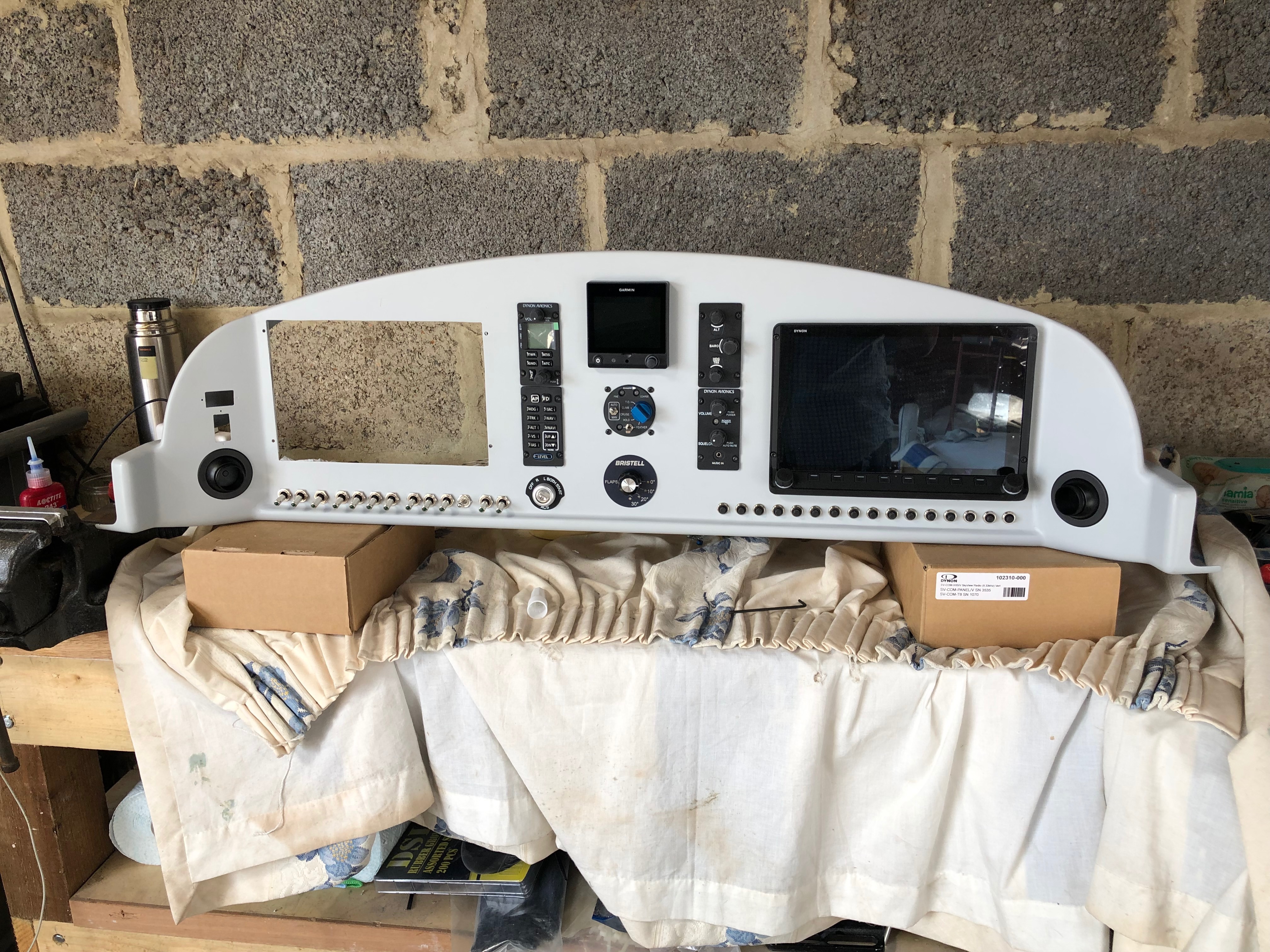
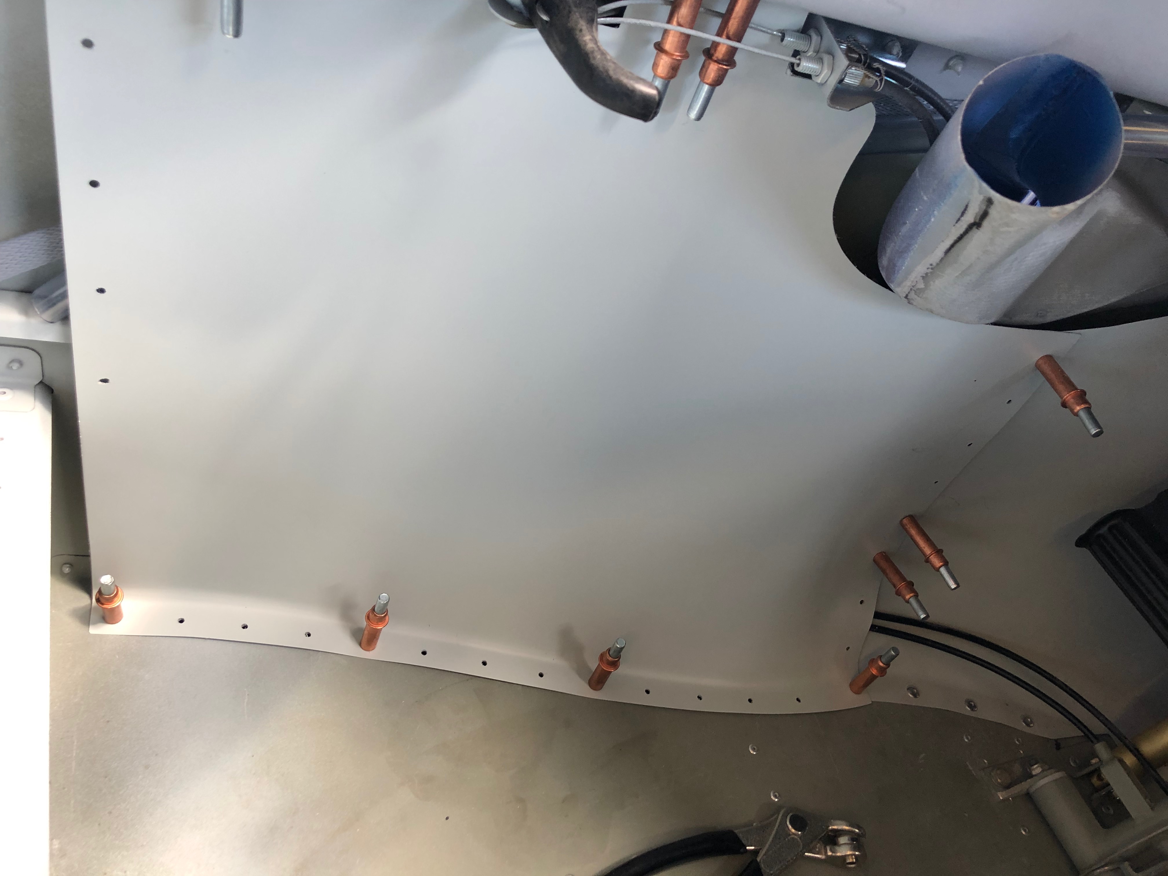
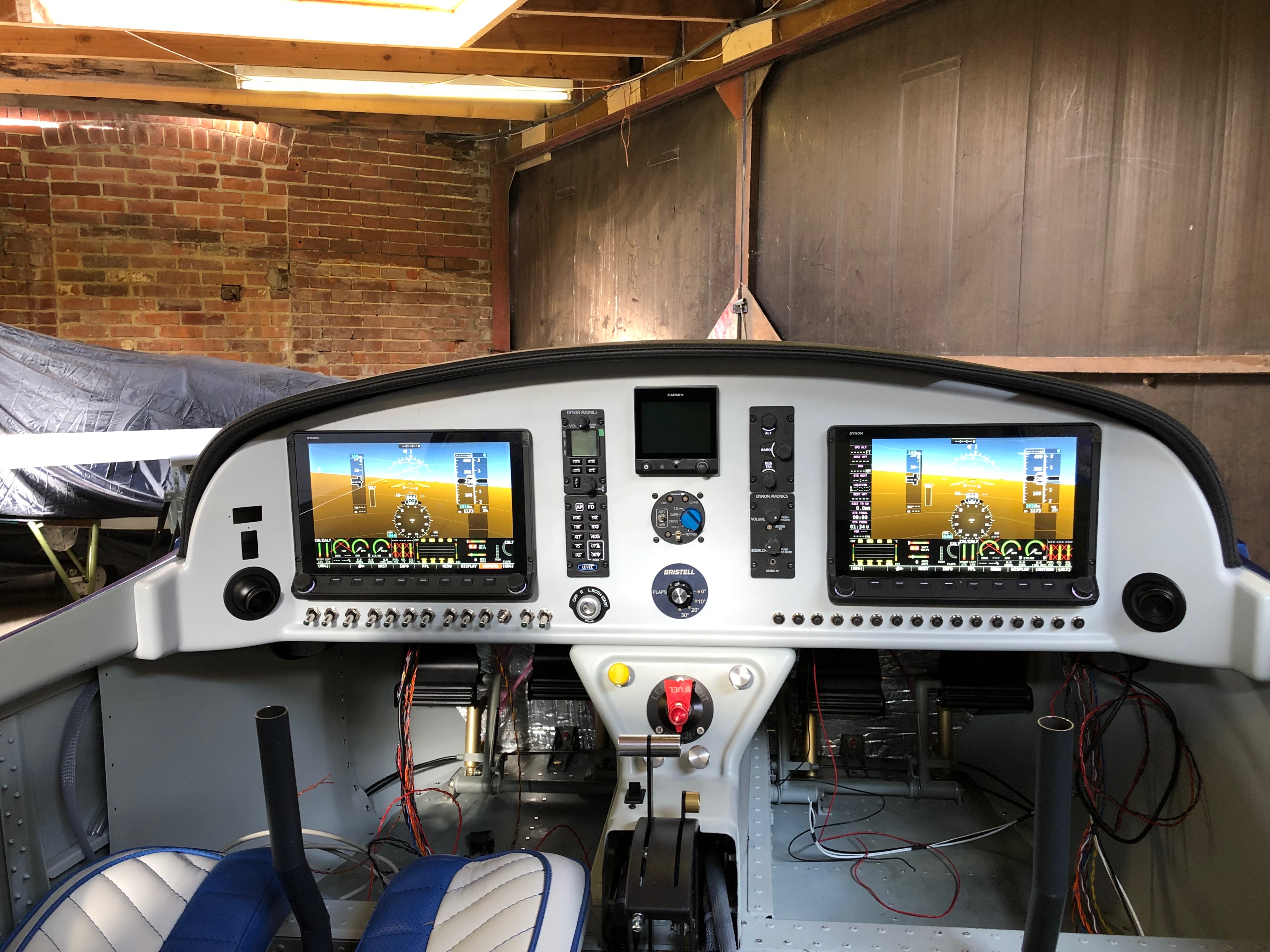
The spinner of the Airmaster which would look even better on the front of the aircraft. The only problem is I don’t have all the components to fit it. I found out today that I’m missing the M8 Round-Neck Nut Set (of course I am!) They’re not supplied with the engine and not supplied by the propeller manufacturer! Quite amazing really. However a call to CFS Aero and a set are on the way to me for tomorrow.The G5 has now been installed and one of the Skyviews. The interior footwell panels are pre-drilled which makes it easier however they still need trimming and you need to make sure you know how they are fitted before starting to rivet. I’ve used some Clecos to secure the panel before riveting.On the rear panels I’ve made them removable but these don’t need to be removable so I’m riveting them.Of course one was easy to fit and the other took ages…However all done now and looks quite neat. There’s carpet to cover the floor area which will make it look a little less utilitarian!Now that’s done and the panel is complete it can be fitted.It’s secured with 2 screws either side of the panel and 3 screws that screw into the centre console. It provides a very secure fit but may benefit from a couple of lightweight supports at the top of the panel.The final panel, all the network cables have been fitted and the glare shield fitted temporarily and powered up using the backup batteries. The G5 backup battery has finally run out so I can’t switch it on which is a shame but overall I’m pleased with the result.
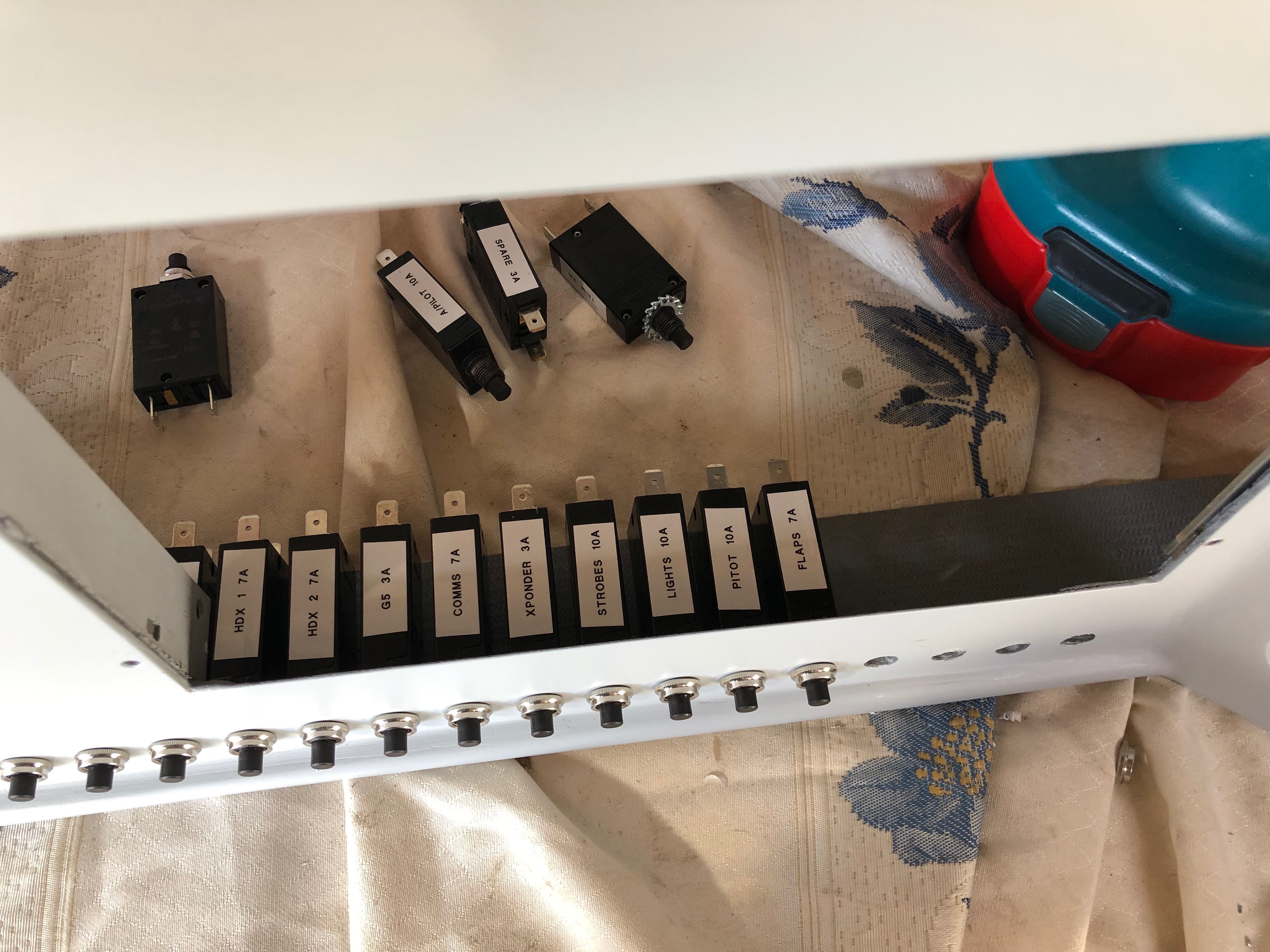
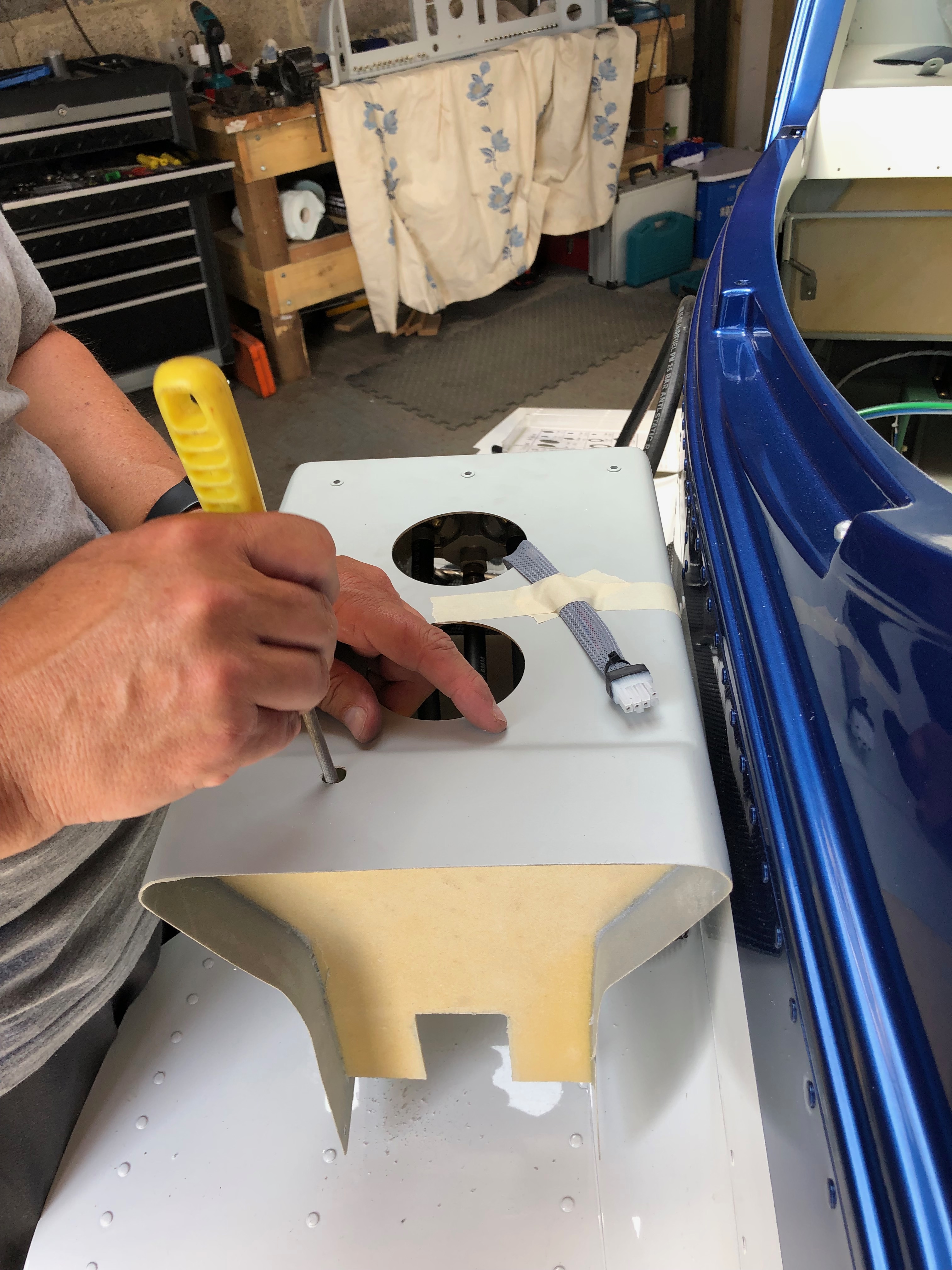
A couple of jobs to focus on today. The first is to fit the circuit breakers and second is to start the fitment of the centre console that includes the control cables for Carb Heat, Park Brake, Cabin Heater, Demist and fuel pipes to the selector and tank lines.
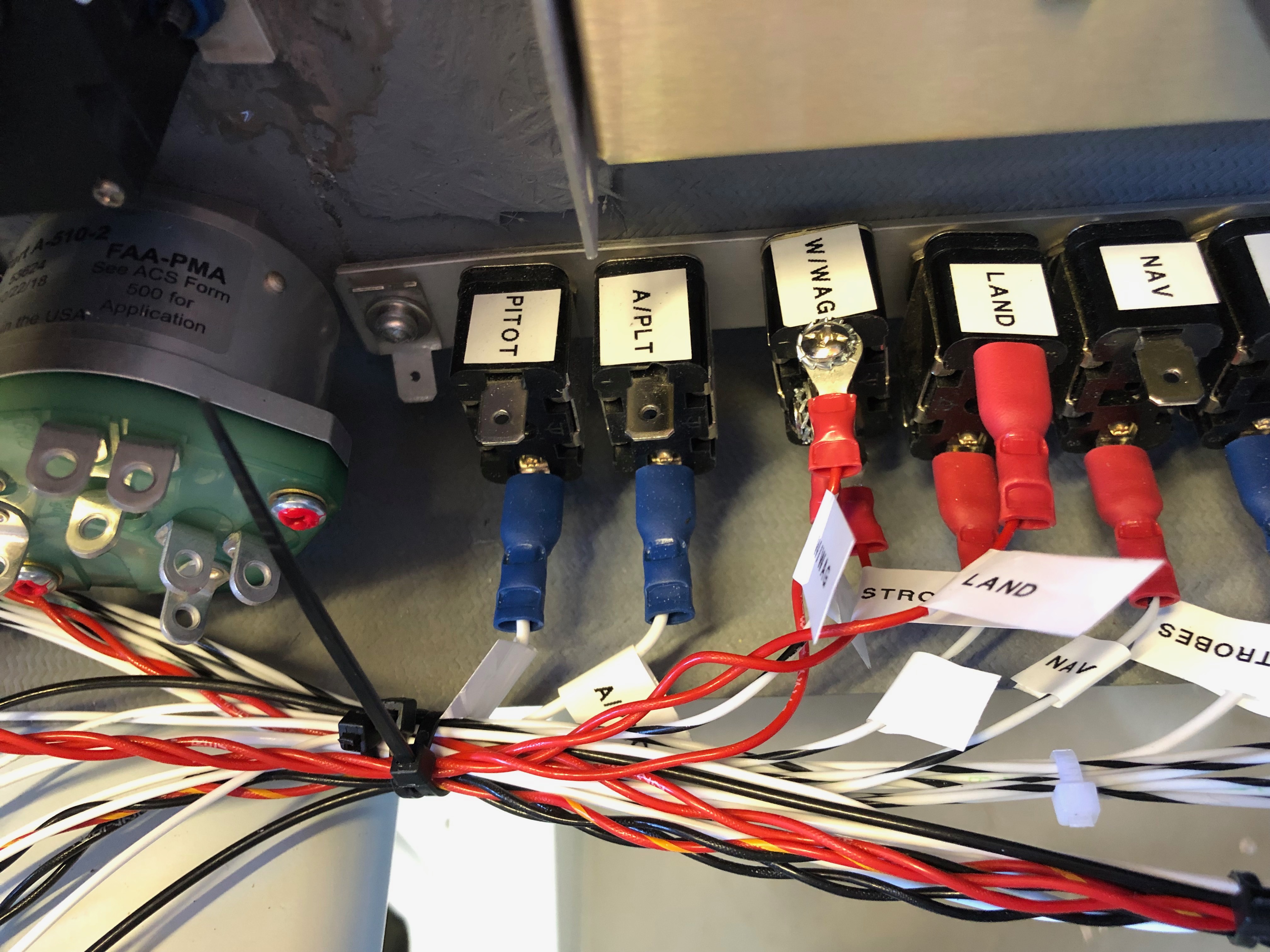
I’ve printed labels using an electronic printer so I can easily identify the circuit breakers and switches once fitted.Unlike the switches that have a hex nut and can be tightened with a spanner the circuit breakers have a knurled ring that is difficult to grip. I found the best way was to adjust some mole grips so they gripped the ring firmly that allowed me to turn the the ring a quarter of a turn at a time. It took some time but got the job done. All the switches and circuit breakers are in now. Very pleased with the result, looks quite tidy!The cables used to control various items have to be routed so they don’t snag. After a couple of trial fits the best route from the front of the panel to the control is to exit the centre console via a hole at the rear. Three cables will exit this way and the fourth which operates the park brake will exit the end of the console and loop back in. This makes sure that the control operates in the correct sense i.e. push is off and pull is on. With the console in place I can test the routing again and once checked I can drill the other holes.The carb heat cable is connected to the carb heat control using a radio control model clevis.The centre console ready to be installed showing the park brake cable that loops round and back in connect to the park brake. Without doing this the park brake would operate incorrectly.Chris has been helping me over the last couple of days but before he left I thought I’d install a screen and power it up. With the ADAHRS unit installed and wired it’s the first time that I’ve seen it myself – looks quite impressive!
A couple of days away to do some flying and meet up with an old mate for a beer or two and now back to the grindstone!
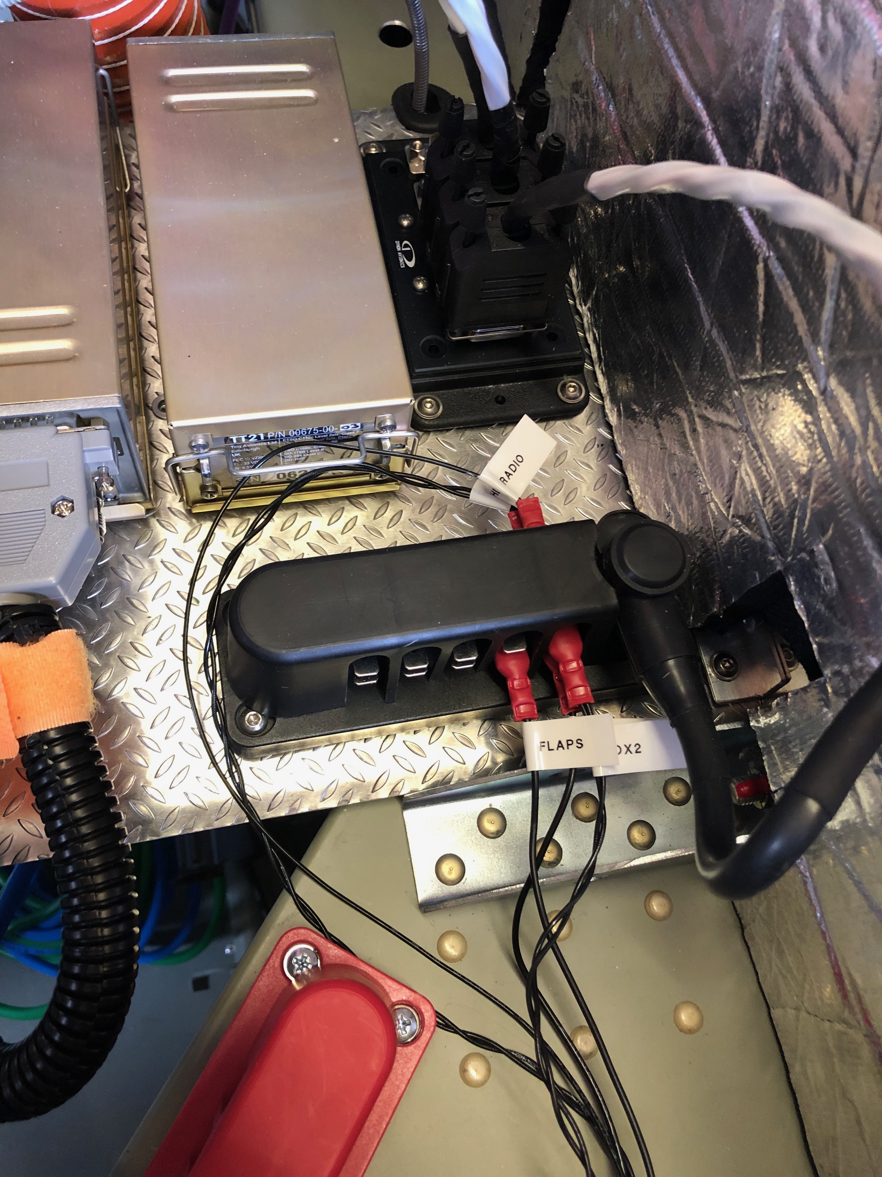
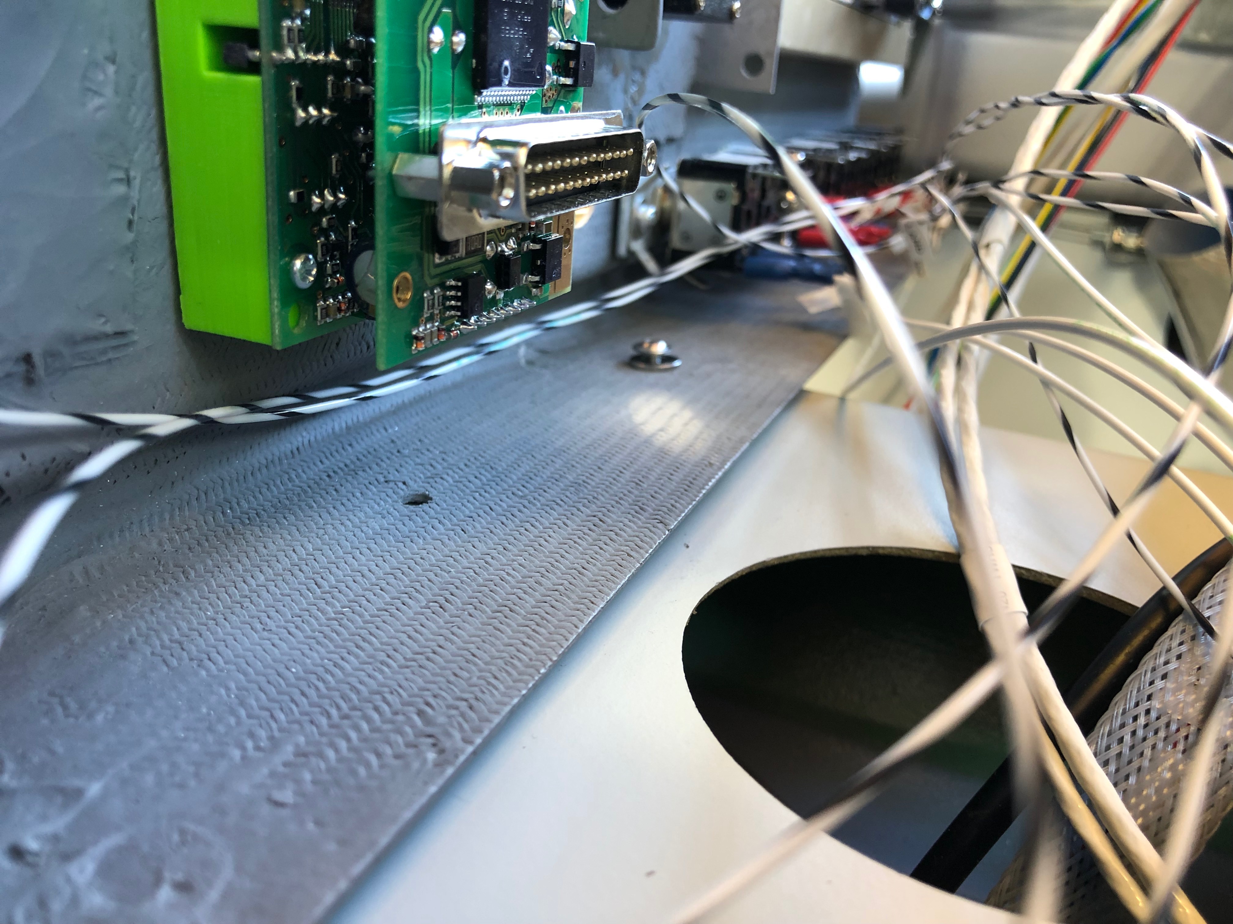
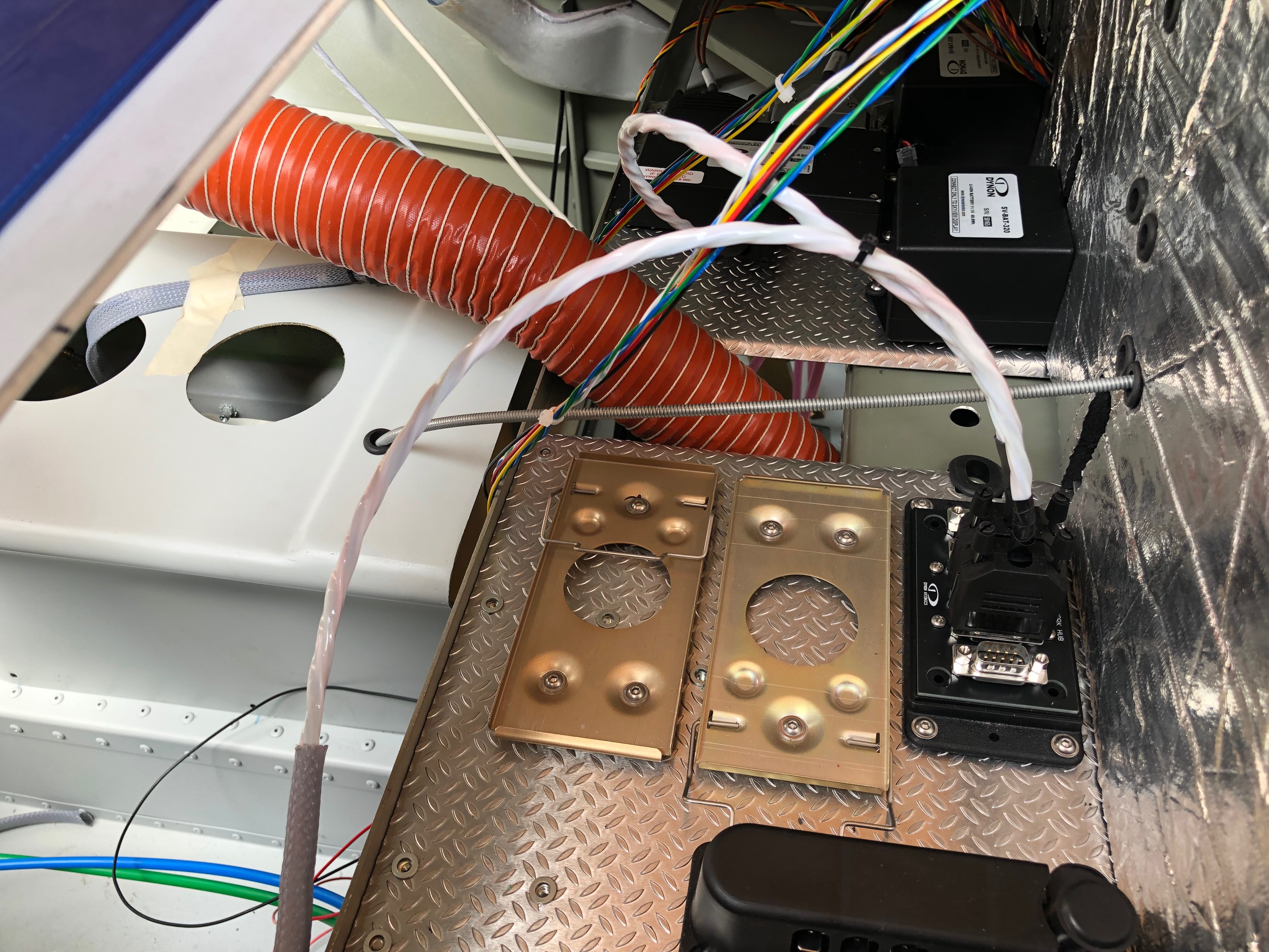
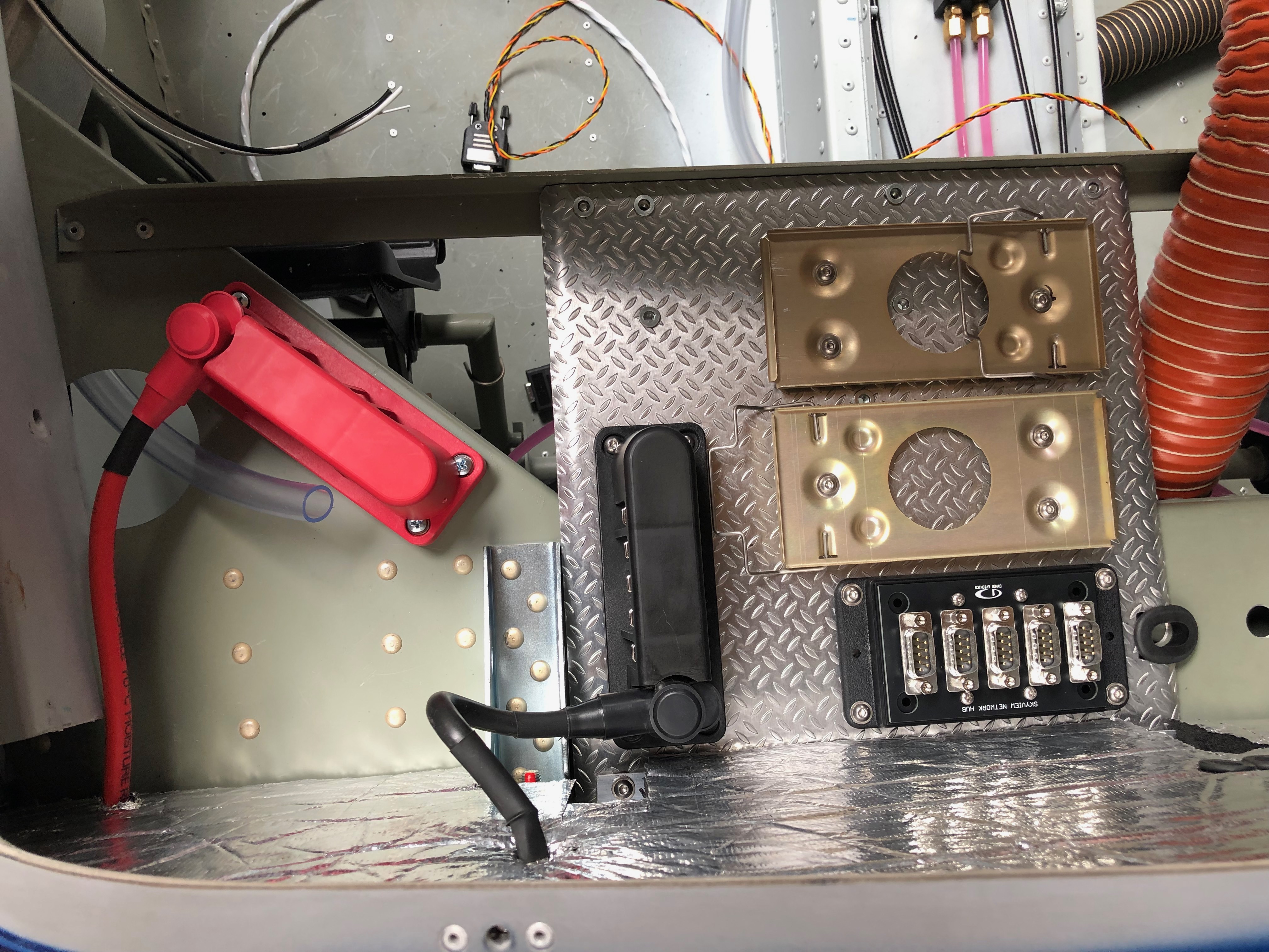
A couple of items to complete the installation of the primary power system. The power and earthing arrangements that I’ve decided to use necessitates rearranging the items on the comms tray. Once this stage is complete and with virtually all the other activities complete until the prop arrives it’s time to move on to wiring the all the systems together. It’s getting to the stage where I need to finalise my panel design and start cutting it out. I haven’t decided whether I will do it myself of get a company to water cut it.
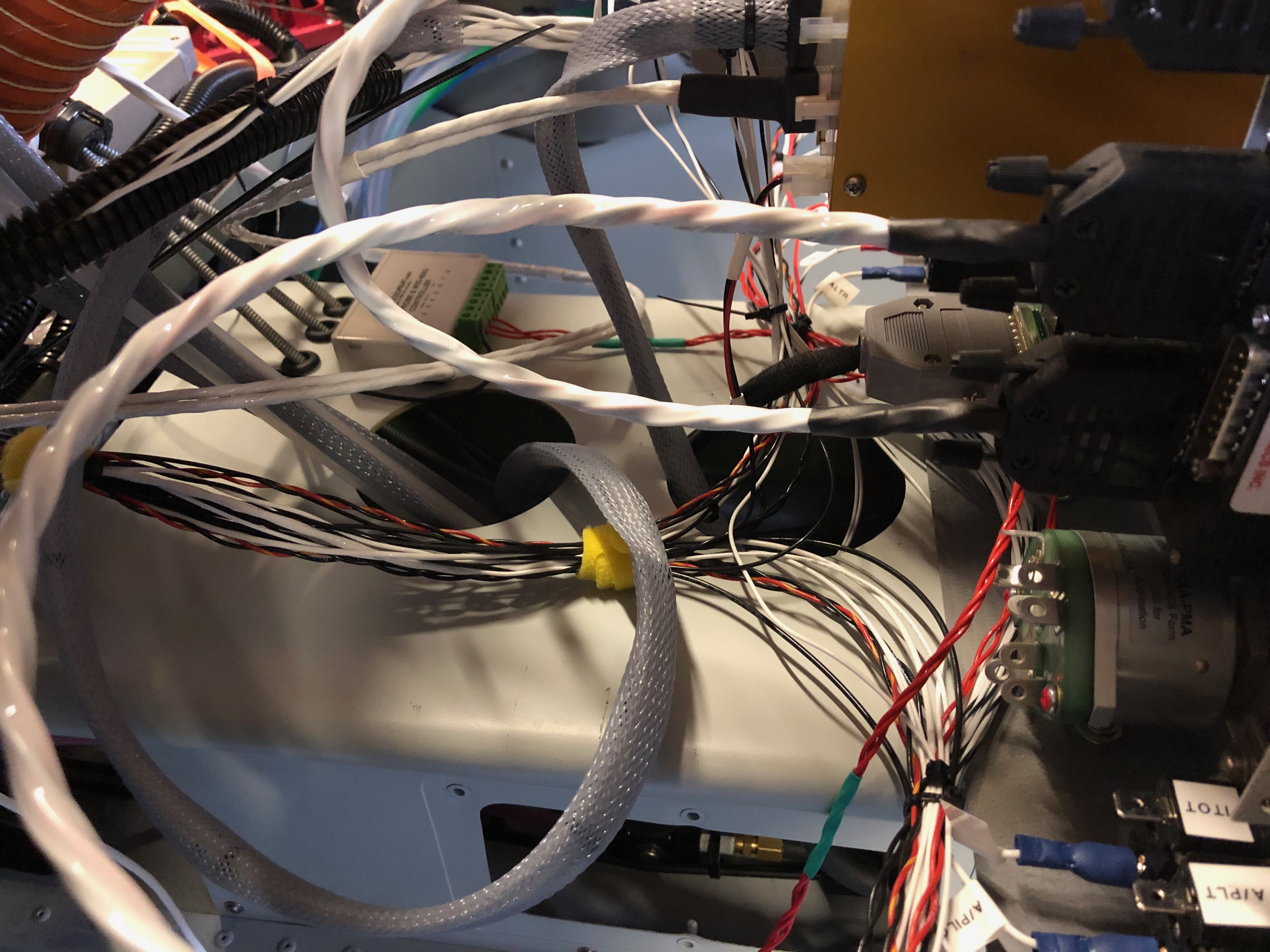
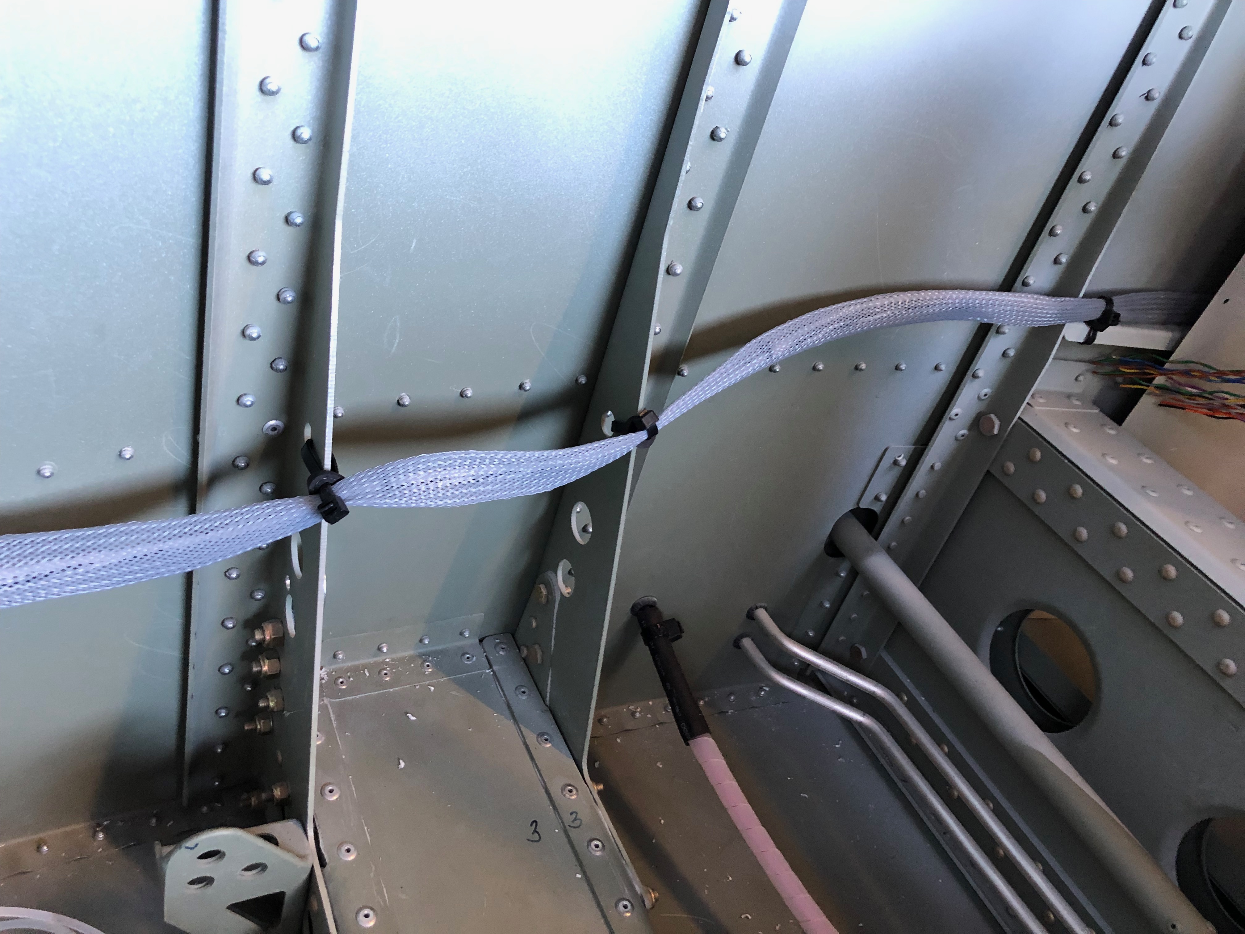
I decided to use a neat 20 way earthing block (VTE 120amp busbar) that complements the power distribution block that I’ve already installed. Where to mount it was an issue but thought the comms equipment tray would work well and shouldn’t produce any interference. So an hour or so was spent trying to work out the best position to ensure ease of access and sensible wiring runs. I think this is the best option. I made up a short earth wire terminated with and 8mm on one end to bolt to the firewall earth stud and 6mm the other to connect to the busbar. This solution will provide 20 feed and earth connections that should be adequate as I have 15 circuits to cater for in the current electrical design.The last wire to add is an earthing strap that is bolted on to the starter motor. This will ensure that the start draws all it’s power from direct connections and not through the aircraft frame or engine mount .The completed primary power system.Onto running the wires and harnesses in that I’ve made into the aircraft and ensuring that they don’t get damaged during service. This is the ADAHRS network cable. I’ve chosen expandable braided PET cable sleeve. It’s tough, very light and is easily installed. Once the cable is run in it can be secured with cable ties. This will be hidden behind the interior panels that I’ve decided to make removable so I can get to these when I carry out my annual checks.For harnesses with connectors on I’ve chosen flexible split conduit which is tough, and light but a little more bulky. The split in the conduit allows me to slip it over my pre-made wires.With all the wires and services that will eventually be installed I have to make sure that the installation remains neat and tidy that will facilitate easy maintenance, good protection of the various services and easier fault finding if I ever have a problem.
Not a lot of action today as I was looking at the avionics kit to see where it can all be mounted so just mounted the VHF aerial.
The top surface just behind the canopy is already drilled for VHF whip aerial.
The aerial to be fitted has a BNC coaxial connection on it’s base that can be accessed from within the rear cabin.
The screws that fix the aerial onto the fuselage have cup shaped anti shake washers to hold them.
To ensure that water doesn’t make its way past the screws and down the threads I’ve used some silicone to seal them before tightening them.
The finished installation after running some silicone sealer around the base of the aerial.
To get an idea of how the avionics connect together I laid it out and connected it up. I’d already charged the backup batteries up so they allowed me to power most of the system up. The ADAHRS, Servos, Radio and Transponder can’t be powered up as it needs wiring but it gives me a good idea of how it can be laid out in the Aircraft.
Following the build of my Bristell NG5 Kit No. 382 Registration G-MLSY