Tuesday was a non event as I was ill with some stomach bug which left me very lethargic.
Back to full strength Wednesday but there are less and less jobs to do as the days pass. It’s very windy today so will leave the engine runs and associated tests until tomorrow. Looking to do final inspection before first flight next week. The original chap can’t do it until after the LAA rally at the end of August which is of no use to me as I’m off to Llanbedr for a couple of weeks Gliding. Luckily Ian has managed to arrange for someone else to do it for me.
I spent the day today doing some ‘little’ jobs.
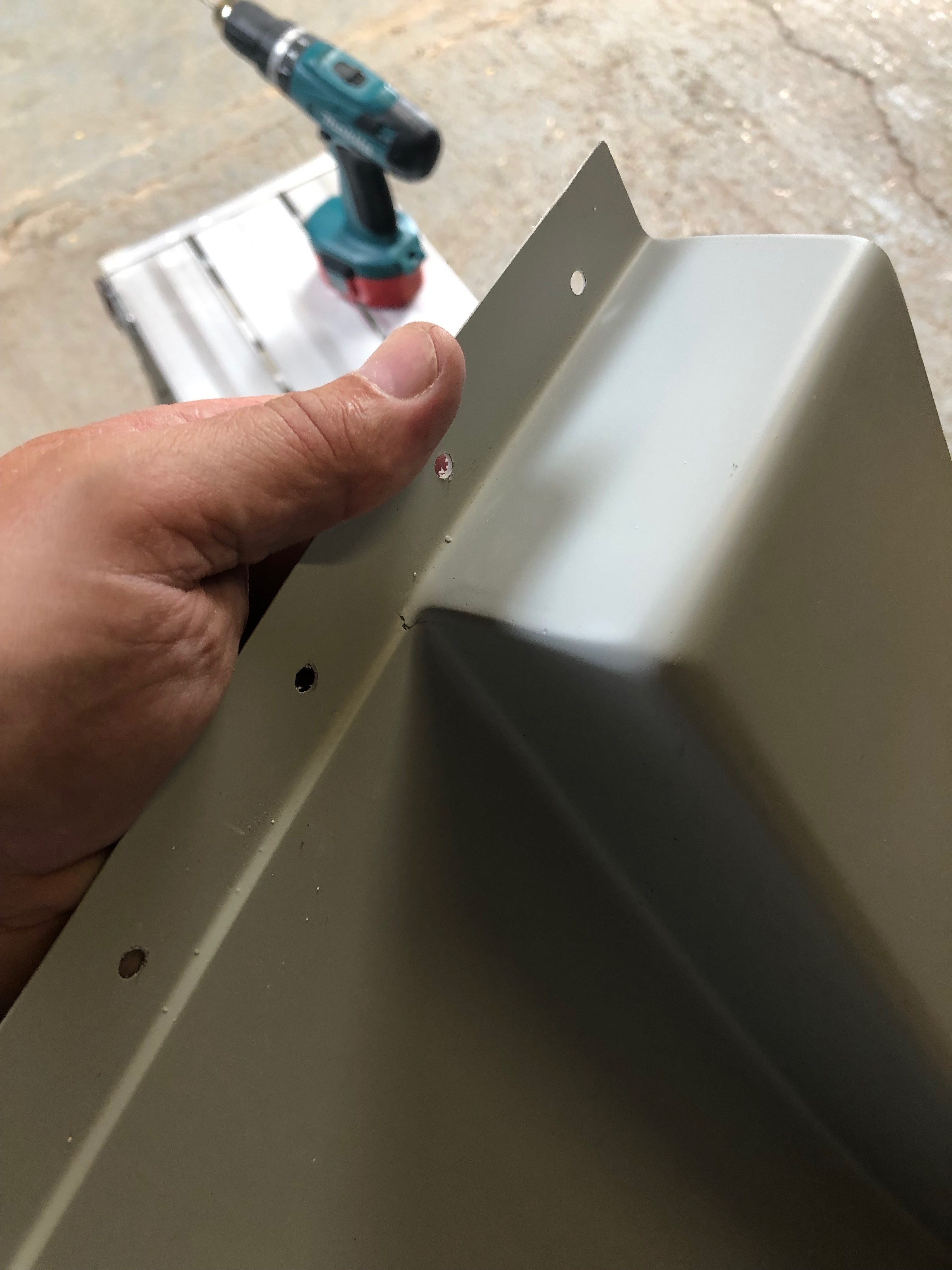
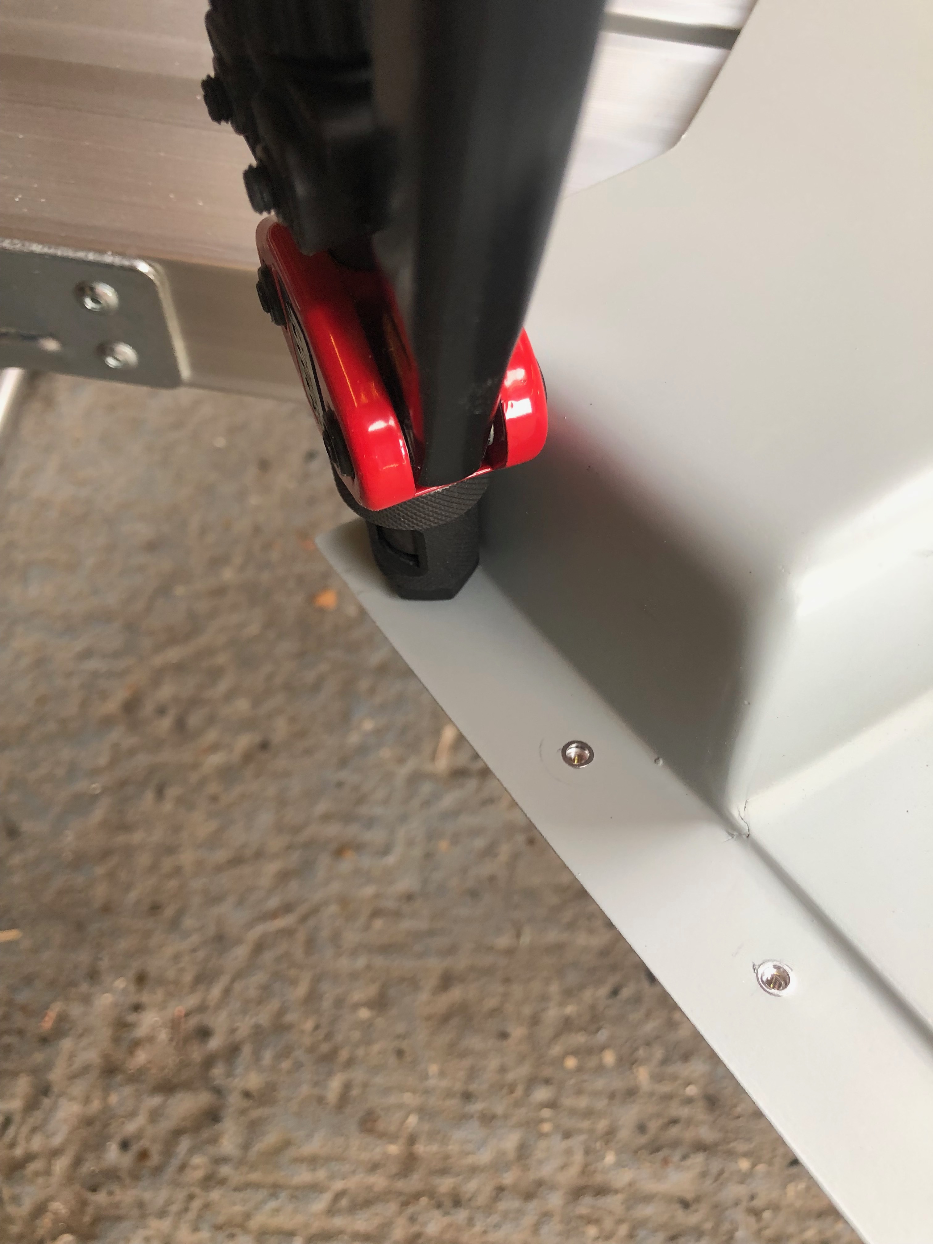
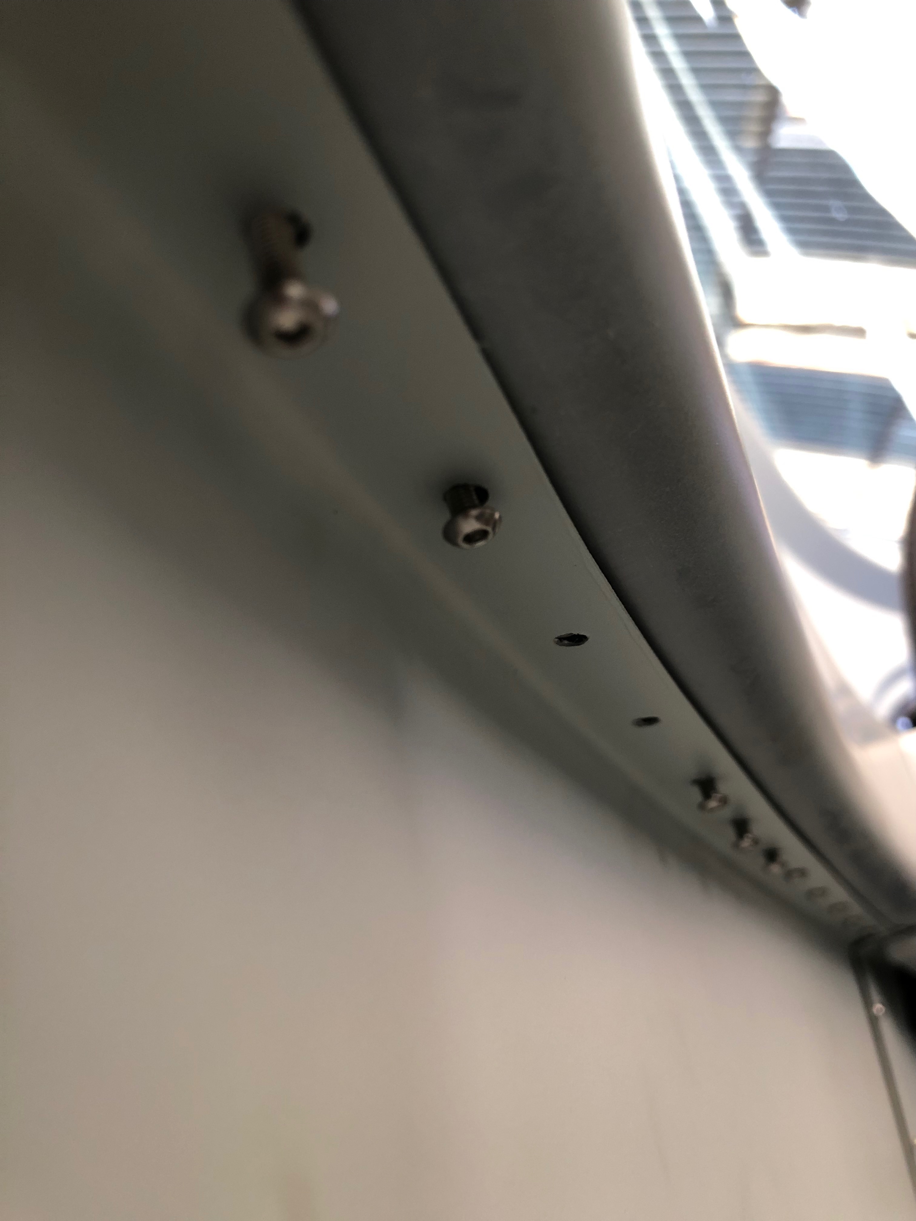
One of the little issues that I found when I first run the engine was the park brake cable travel was too much which could result in the inner coming out of the outer by a couple of mm. I did a small mod, shortened the inner by a few mm and put a more definite cable travel stop on the cable to prevent it pulling out. It works a treat now as do all the other controls.Earlier on in the project I decided after a conversation with Ian to use M3 rivnuts and screws to secure all the internal panels instead of rivets. That would allow me or anyone else that does maintenance or wanting to run extra cables in to easily remove the panels to gain access. This is the side armrest panel I’ve used reduced shoulder M3 rivnuts that don’t protrude so much as others I’ve used and are ideal for this job. You have to be careful though as the material is thin and the there’s not much to ‘get hold of’.There’s loads of holes to secure the panel probably because it’s an armrest so there is an amount of downward pressure. Fixing this panel was no easy job as I had to work ‘upside down’ to find the hole for the screw, line it up and screw it in. I was exhausted after this but it worked well.
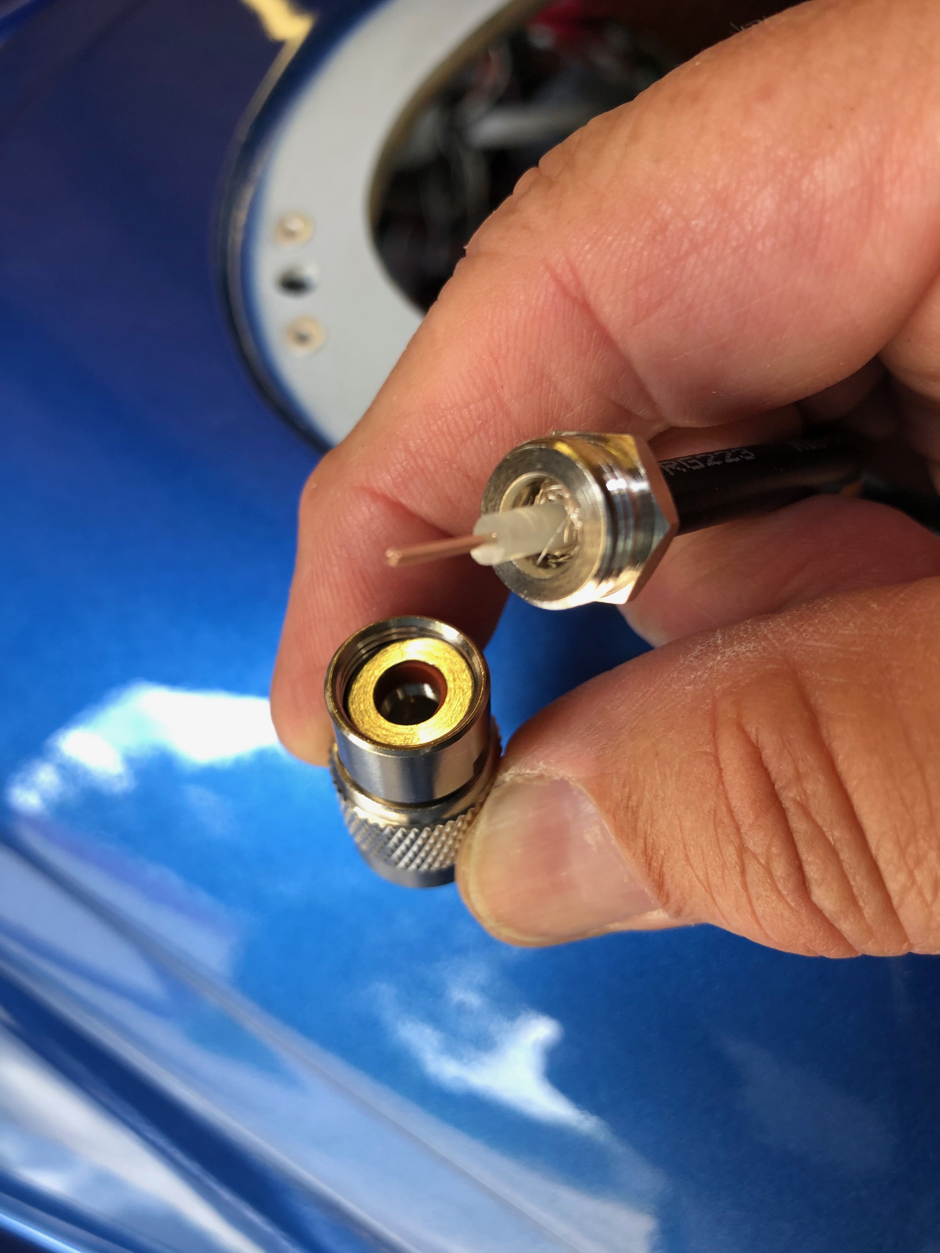
it’s time to fit the wings so I need to add the connectors to the trim, landing lights and heated pitot looms that I have already run in. I’ve also run in the radio coax cable so need to terminate that and carry out a final tidying up of the wiring.
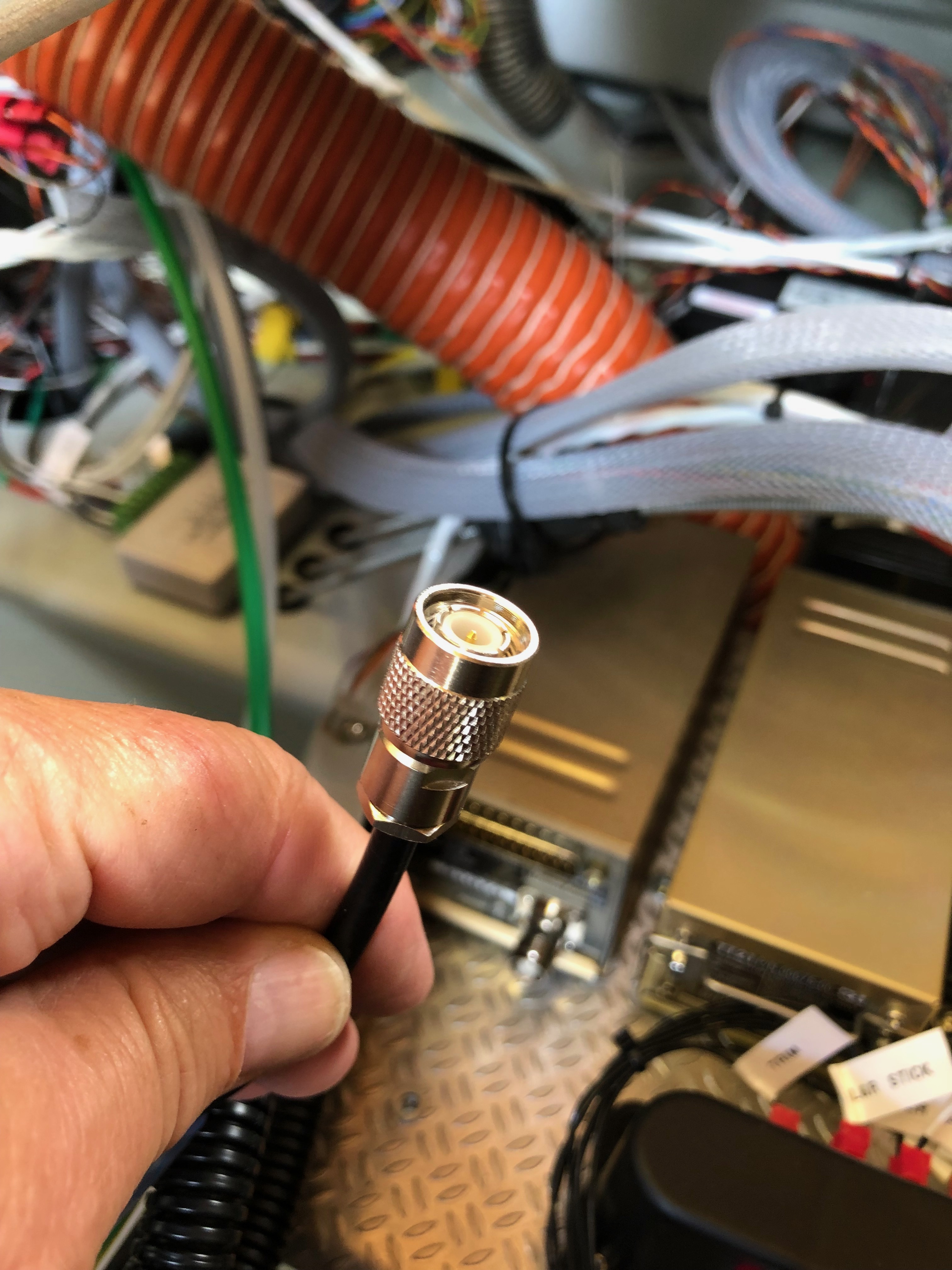
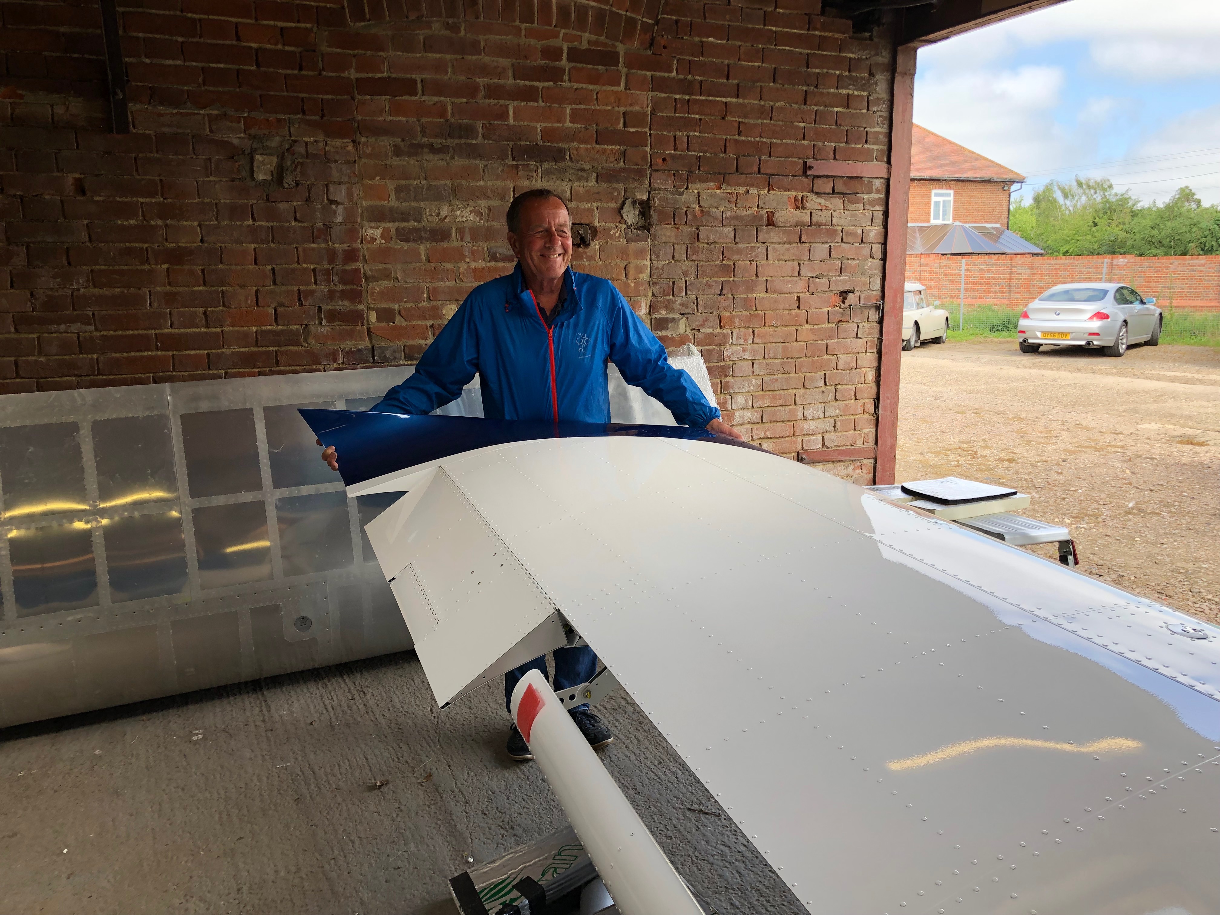
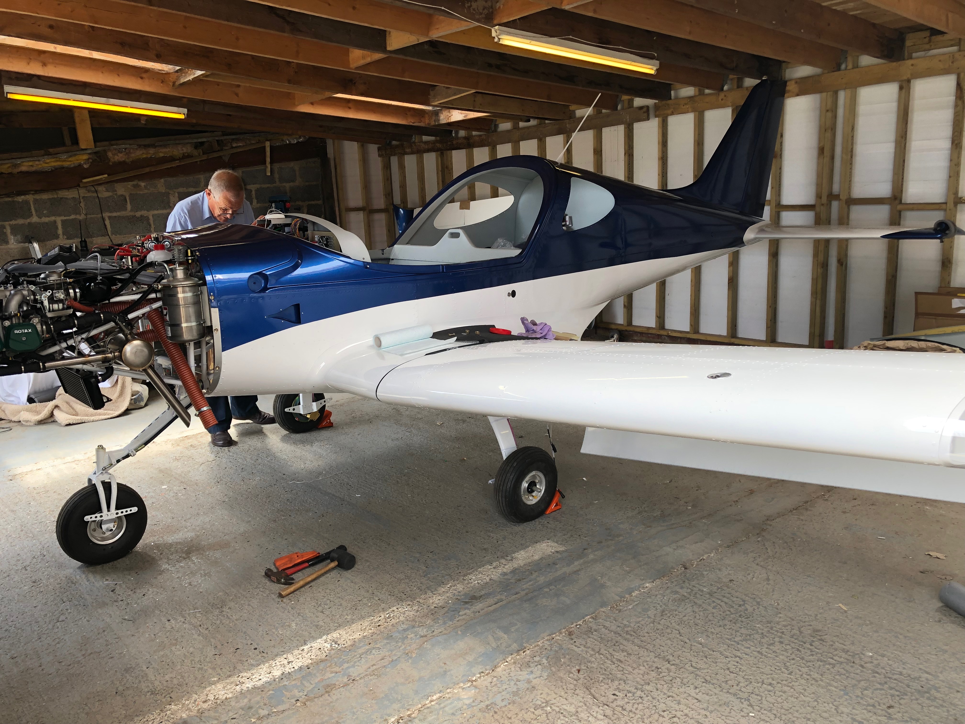
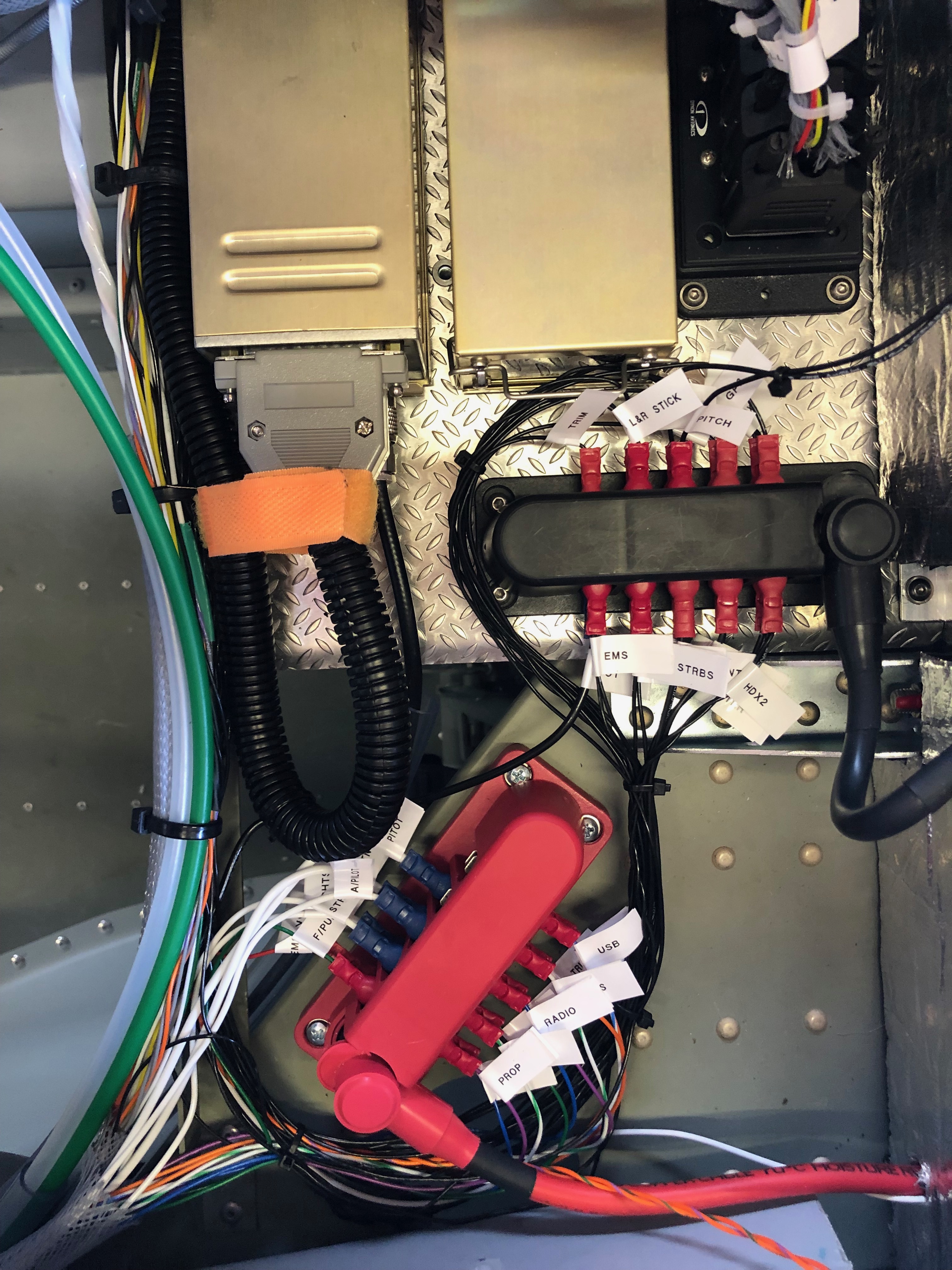
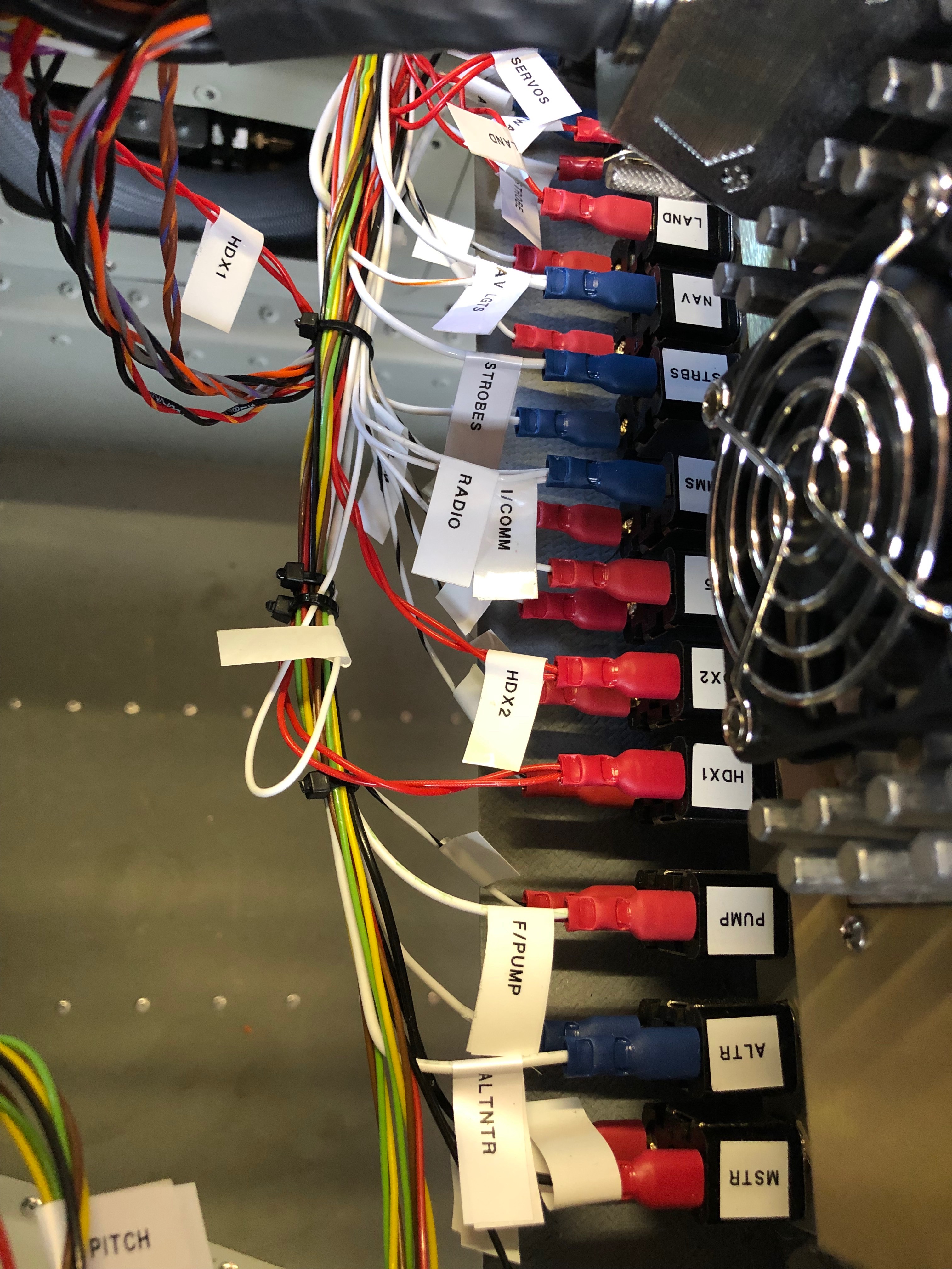
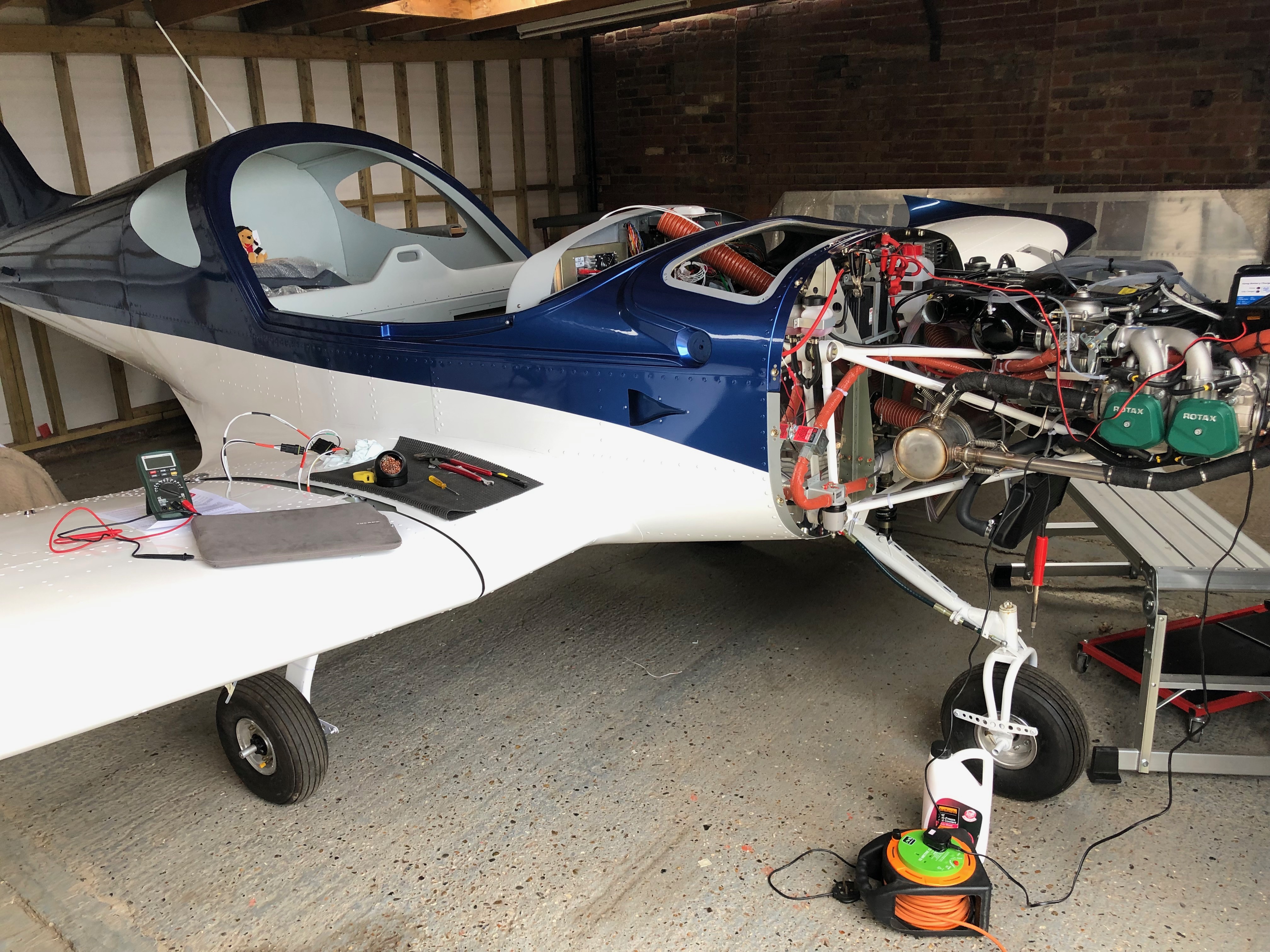
As mentioned before I decided to use superseal connectors as they are failproof and waterproof. I’d already completed quite a few of the connections but was distracted by another job. Whenever I’m distracted I always document what still needs to be done in my project plan.With all the connectors added the next job is to add an Amphenol to the end of the coax cable. It’s quite a complicated connector so I needed to test i on a cut off first. Once cut and trimmed the connector is soldered on to ensure a good connection.The finished connector, fairly straightforward but just needed to be thought about before committing,Now time to fit the wings so I can set all the ailerons, check the pitot, trim, flap, strobe and landing light circuits are working as wired. Ian and Peter Sharpe have offered to help and as usual Ian wears his designer gloves for the wing lift process. He looks quite fetching 🙂 Peter Sharpe at the ‘sharp’ end adding invaluable assistance. Once the wings are attached the main bolts need to be tapped home with a small nylon mallet before the nuts are added.With the wings added she’s a tight fit in the hanger with just 6″ between the front door and rear wall. If I had fitted the prop she wouldn’t fit!Now all the wiring has been completed and checked I can start to tidy th wiring. Ovrall I’m quite pleased with the results. Circuit Breakers……Bus Bars……Equipment trays and connectors…… and switches. All look a lot tidier now.She’s coming along nicely now and it won’t be long before I can start engine tests…
Music: The Greatest Showman reimagined and Snow Patrol.
Finishing off the insulation installation, first fit of centre console, autopilot servo install and filling brake system with Aero Shell 41.
One quick job this morning now all the other pipes have been fitted is to run a piece of piping from the water expansion chamber to the water bottle.
I have been given templates for the insulation so I can cut them to size without too much effort.
Some notches, cuts and holes need to be made to make sure it sits properly on the firewall.
It’s a tight fit behind the rudder pedals which makes it difficult to handle once the backing paper has been removed.
The final pieces are fitted around the heated inlet.
The finished insulation, hopefully this should reduce noise from vibration of the firewall and the engine.
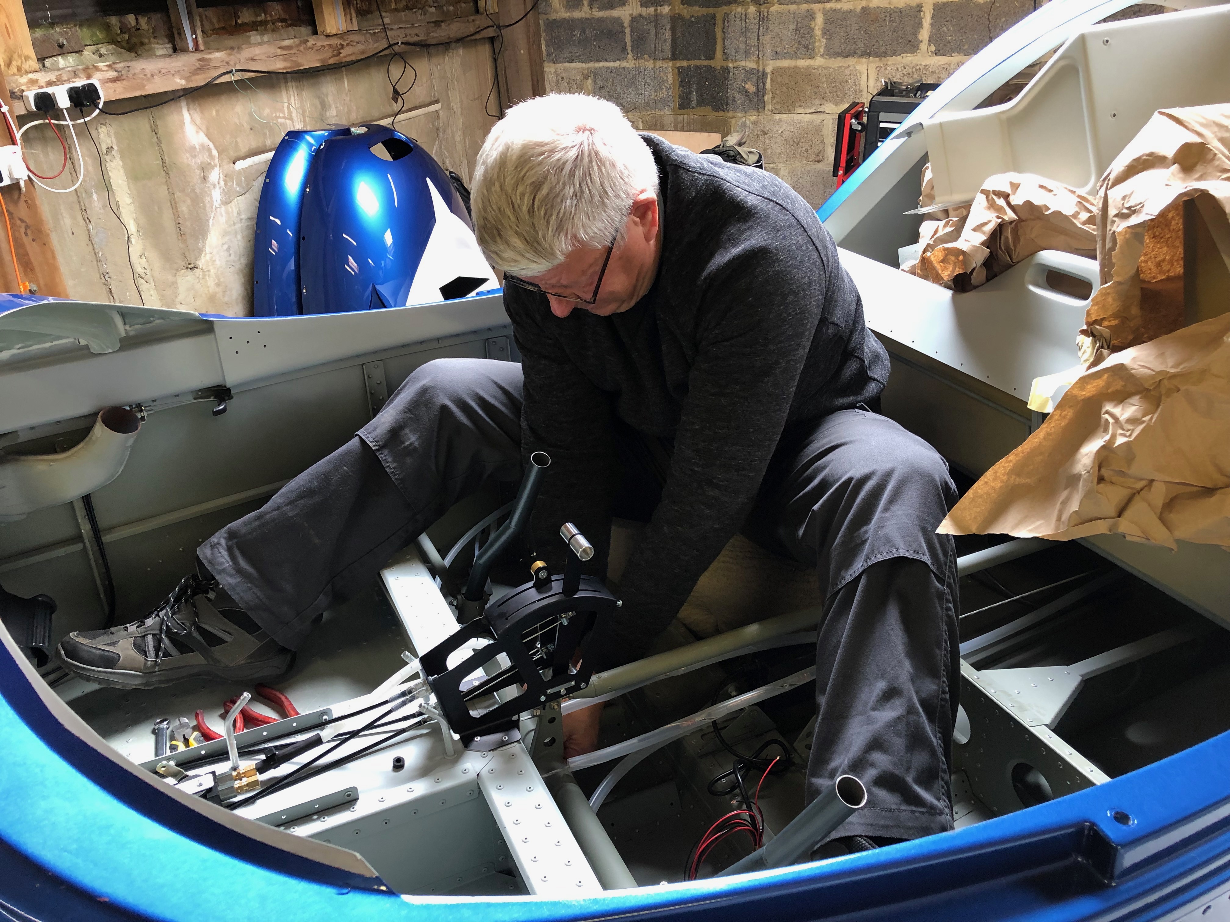
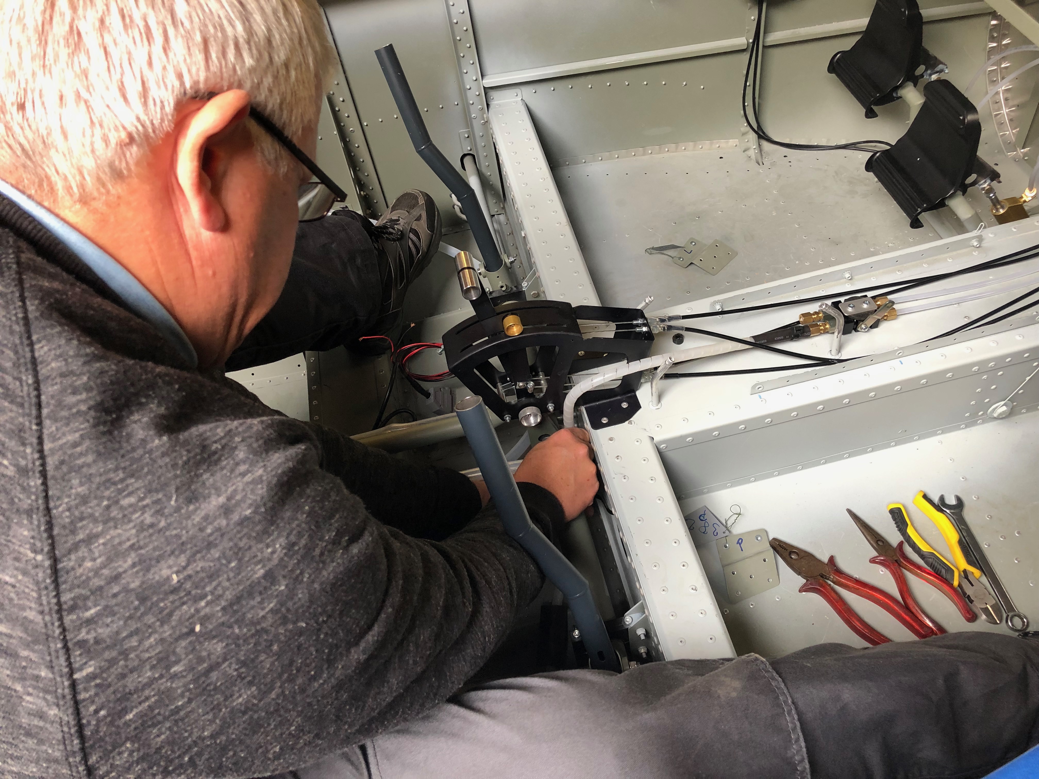
Now the servos brackets are in position the servos can be fitted. First the roll servo.
It’s very fiddly and would have been much easier to fit the servo to the bracket whilst it was out of the aircraft.
The pitch servo with the movement limiting bracket fitted which stops the motor running over centre. I still can’t finish the installation as there were items missing from the kit supplied to me – very frustrating as I can’t refit the controls until I fit the roll servo arm.
A first fit of the centre console in readiness for the fuel selector. Need to check with the instrument panel in place to check that the flap control cable is long enough to fit on the panel otherwise is will need to be mounted here instead which I would like to avoid.
After fitting the insulation need to reconnect and tighten the brake hoses before filling.
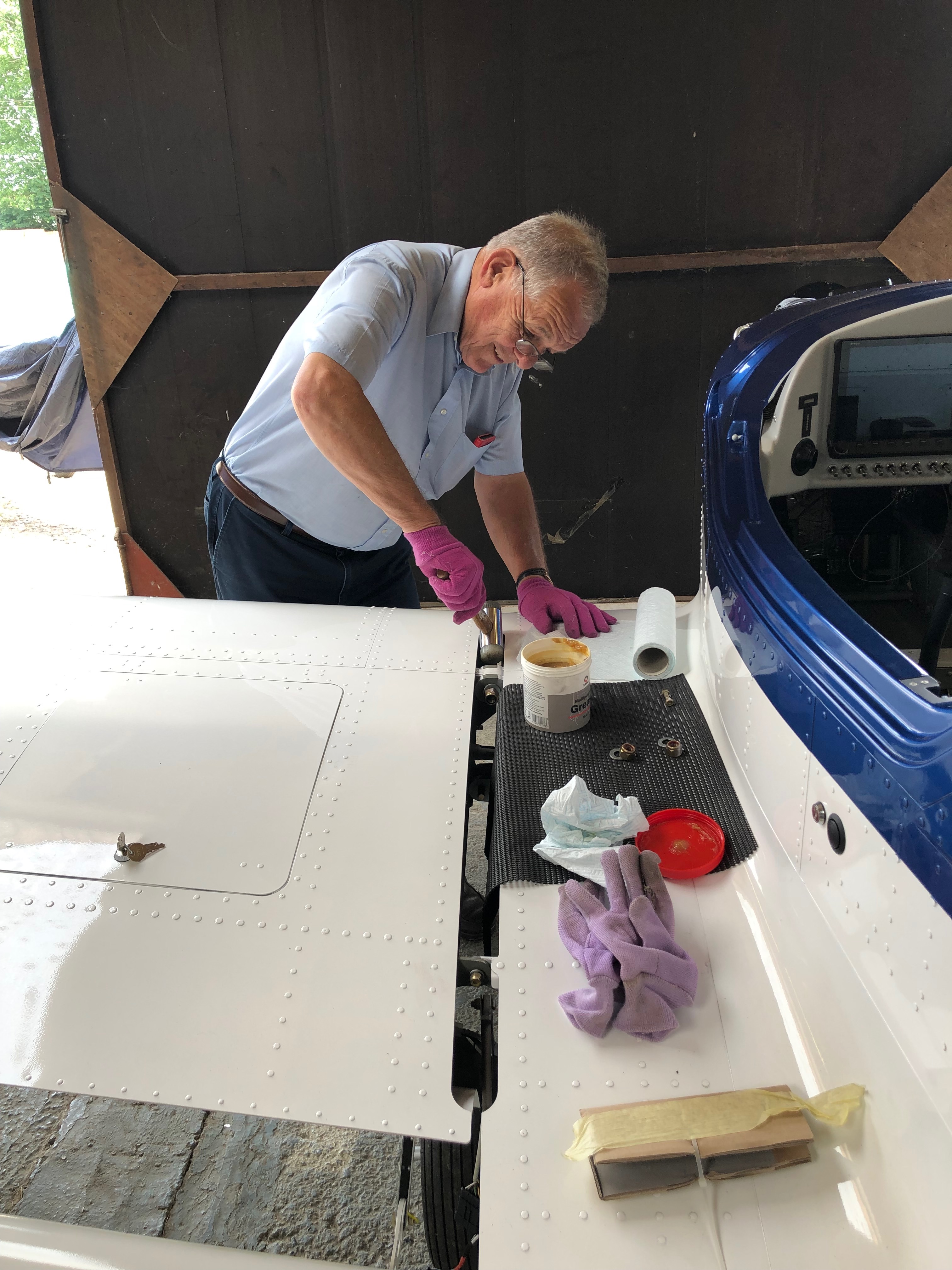
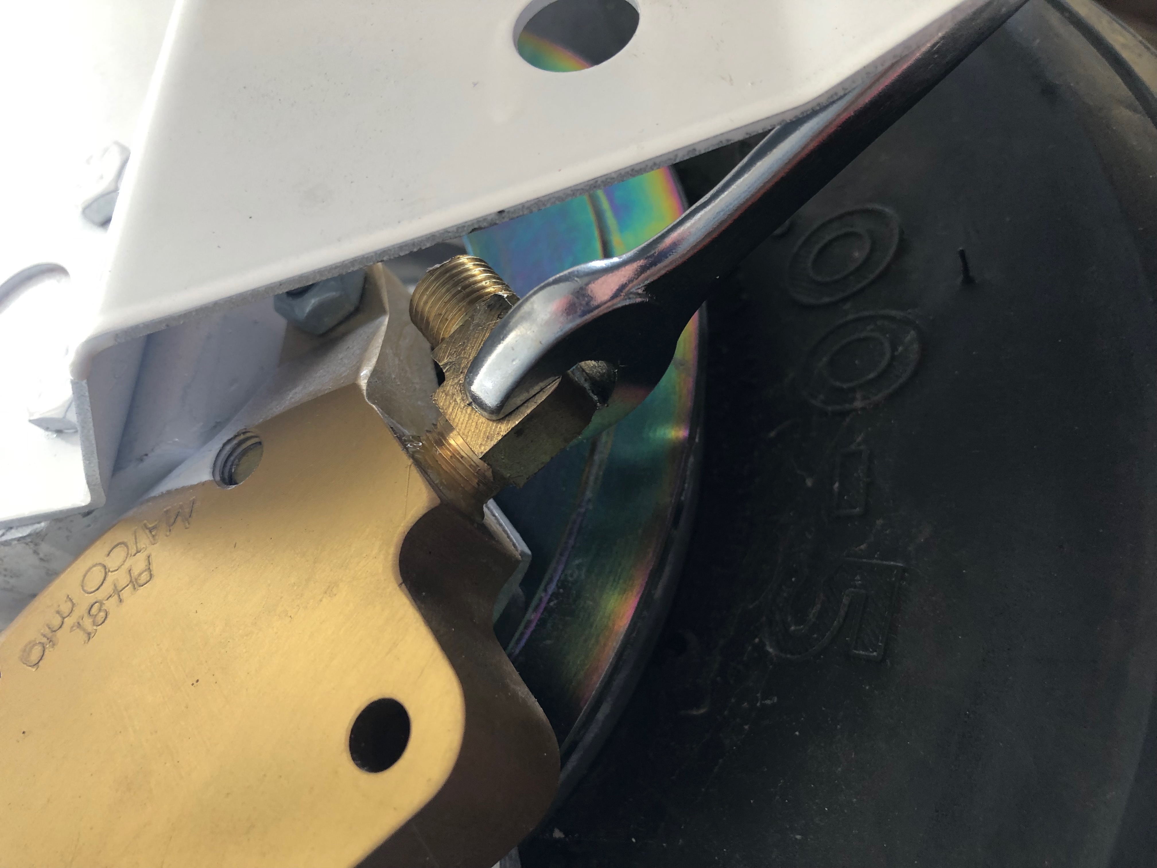
The brake fluid is filled from the bottom so some plastic pipe is wire locked onto the brake calliper nipple so stop it slipping off. The nipple is unscrewed to allow the fluid to flow into the calliper.
An oil can that has been thoroughly cleaned is filled with Aero Shell 41 and the plastic pipe is fitted to the nozzle.
The filling commences after releasing the park brake valve.
When the fluid reaches the brake oil bottle the brake calliper nipple is tightened and the process is repeated for the lefthand side brakes.
Filling complete but some air bubbles are present. They will need to be purged before use otherwise the brakes may not operate properly.
Due to limited space I couldn’t drill the second set of holes for the retention system. Luckily Ian had a 90 degree attachment the allowed me to drill the holes.
The holes for the rivets that will secure the bracket.
Sometimes you have to leave certain jobs because an immediate opportunity comes up for someone to help you swap wings. This is what happened when I had starboard wing up on the stand so I didn’t get chance to fit the strobe light. So today’s the day to do it.
Once the holes are drilled they need to be countersunk otherwise the strobes won’t fit flush.
Some Loctite 243 on the screws and then they are pinched up, not too tightly, otherwise they will disfigure the rubber mount.
The finished job, let’s hope it matches the other wing!
A job I kept forgetting to do is to add a breather pipe to the oil tank.
Now they can be secured with the drip tray and air intake breather tubes that Andy fitted yesterday.
I wanted to try to reduce the amount of vibration and droning from the firewall and noise from the engine. I purchased some sound & vibration deadening heat resistant foil back foam that will do the job.
After cutting to size, I’ve made the service holes to match the firewall and added grommets to make it a neater job.
I used some thinners to remove the printing on the foil before fitting. Looks a good fit.
I now need to undo some of the work I’ve done on the brakes and fit the front lower panels so I can fit sound deadening on the firewall behind the rudder pedals but run out of time today so will finish this job Monday.
Today was dedicated to completing the brake installation and starting on the exhaust wrap.
First up is to add Loctite 577 to the last two hydraulic elbows and fit them to the brake callipers.
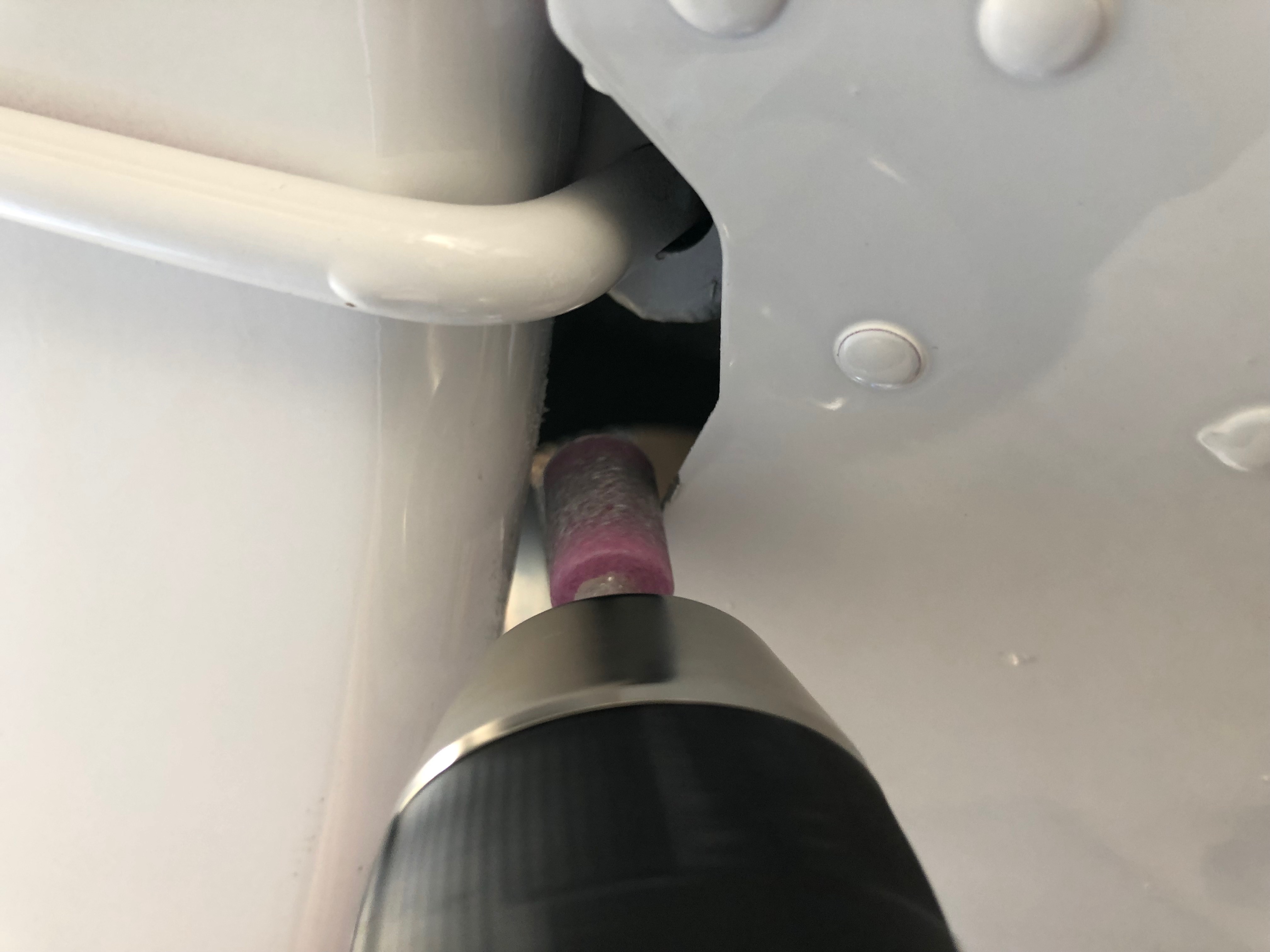
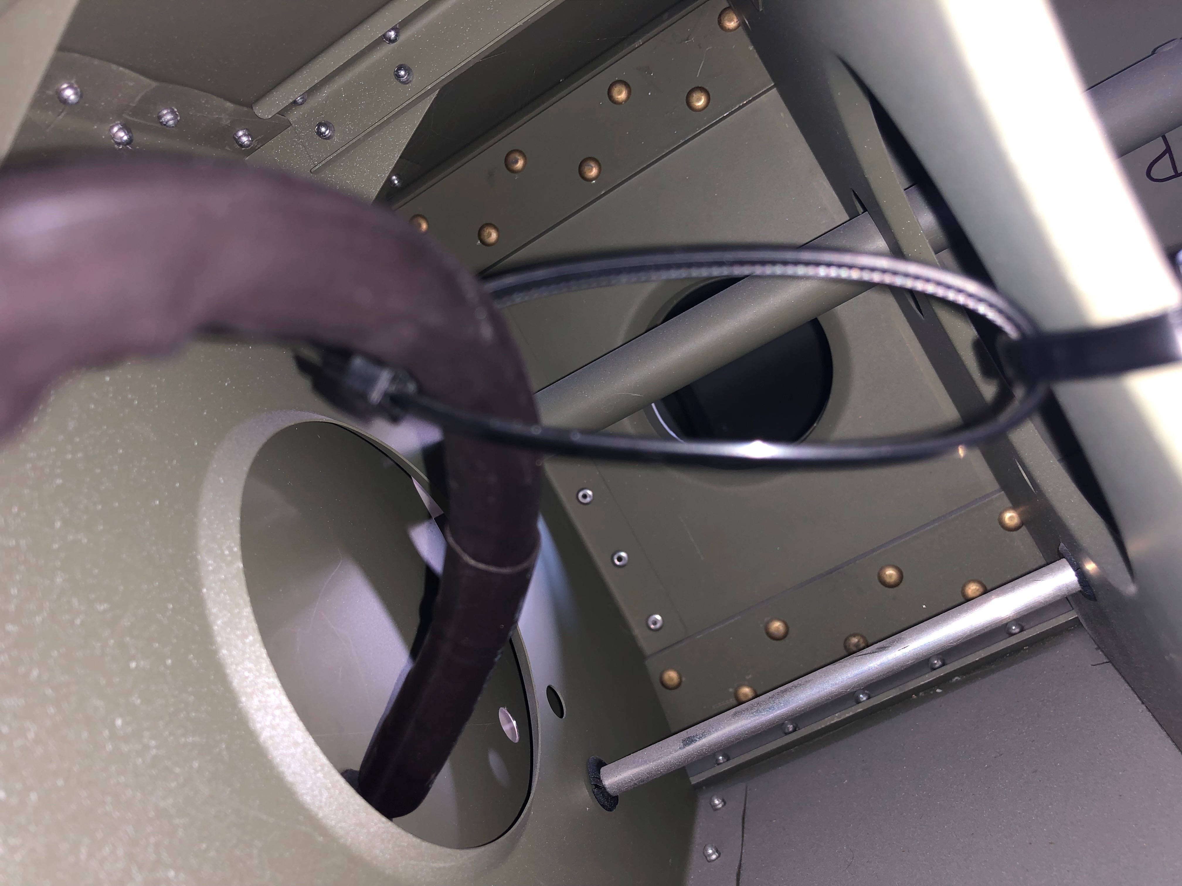
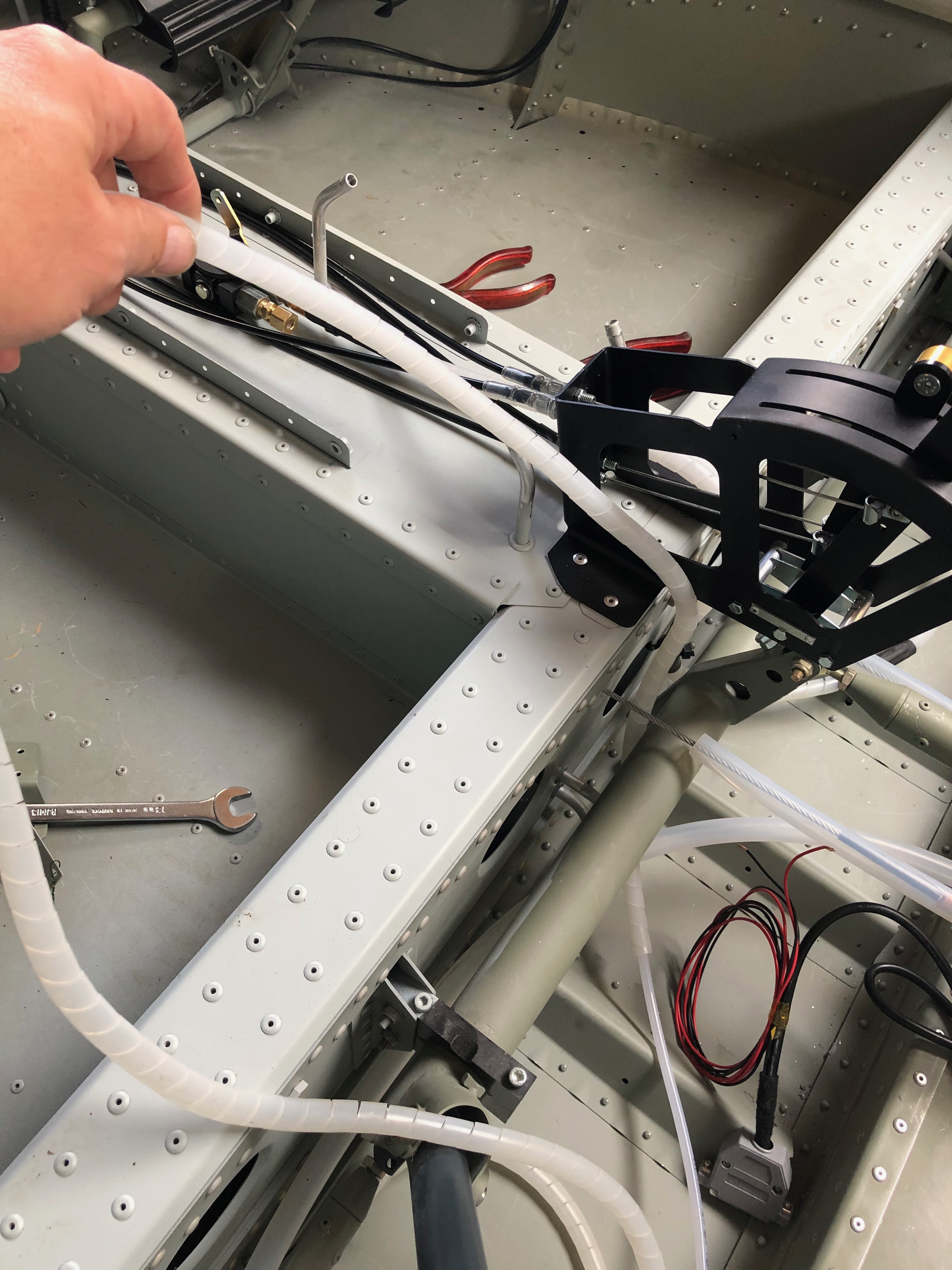
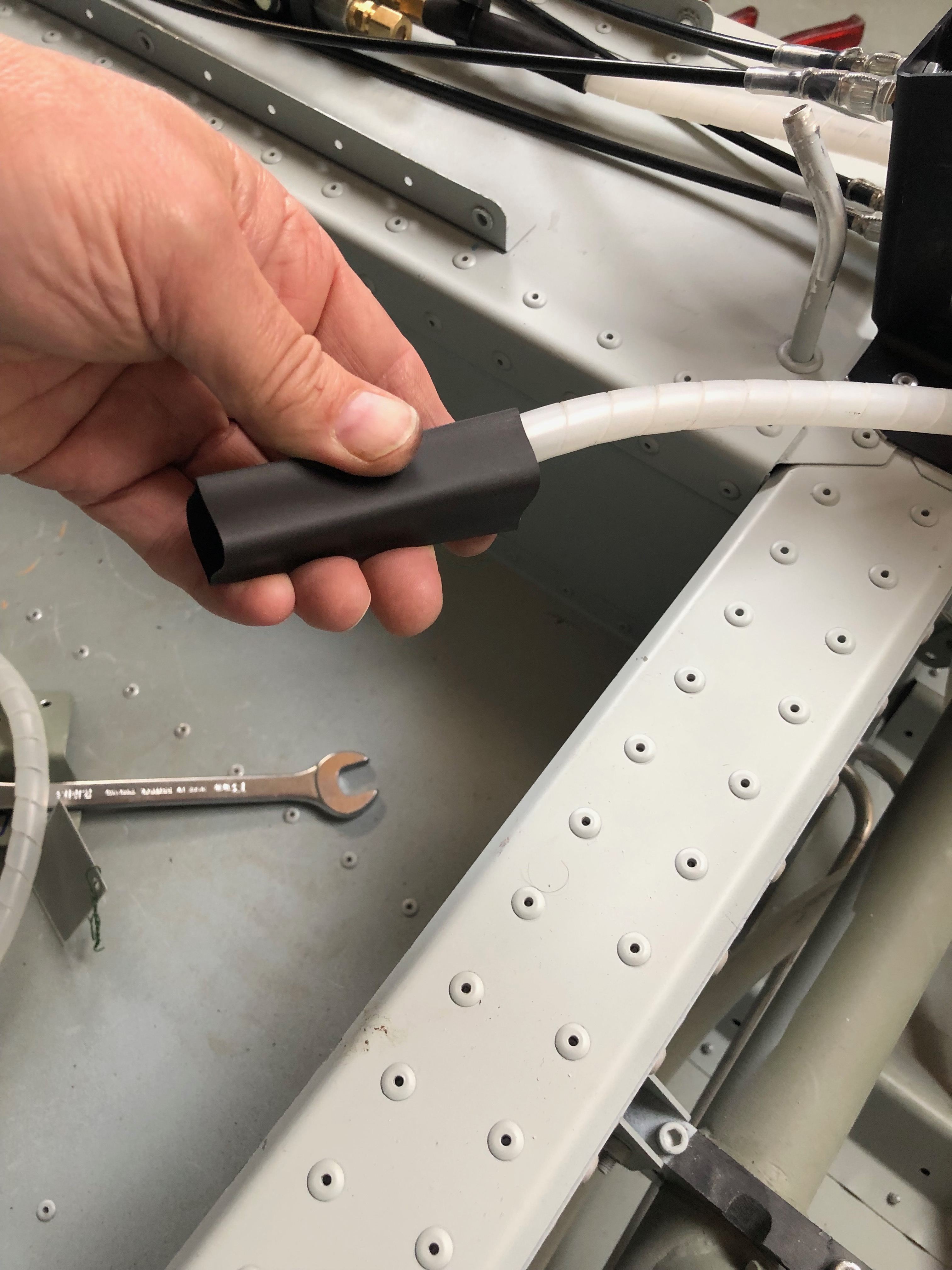
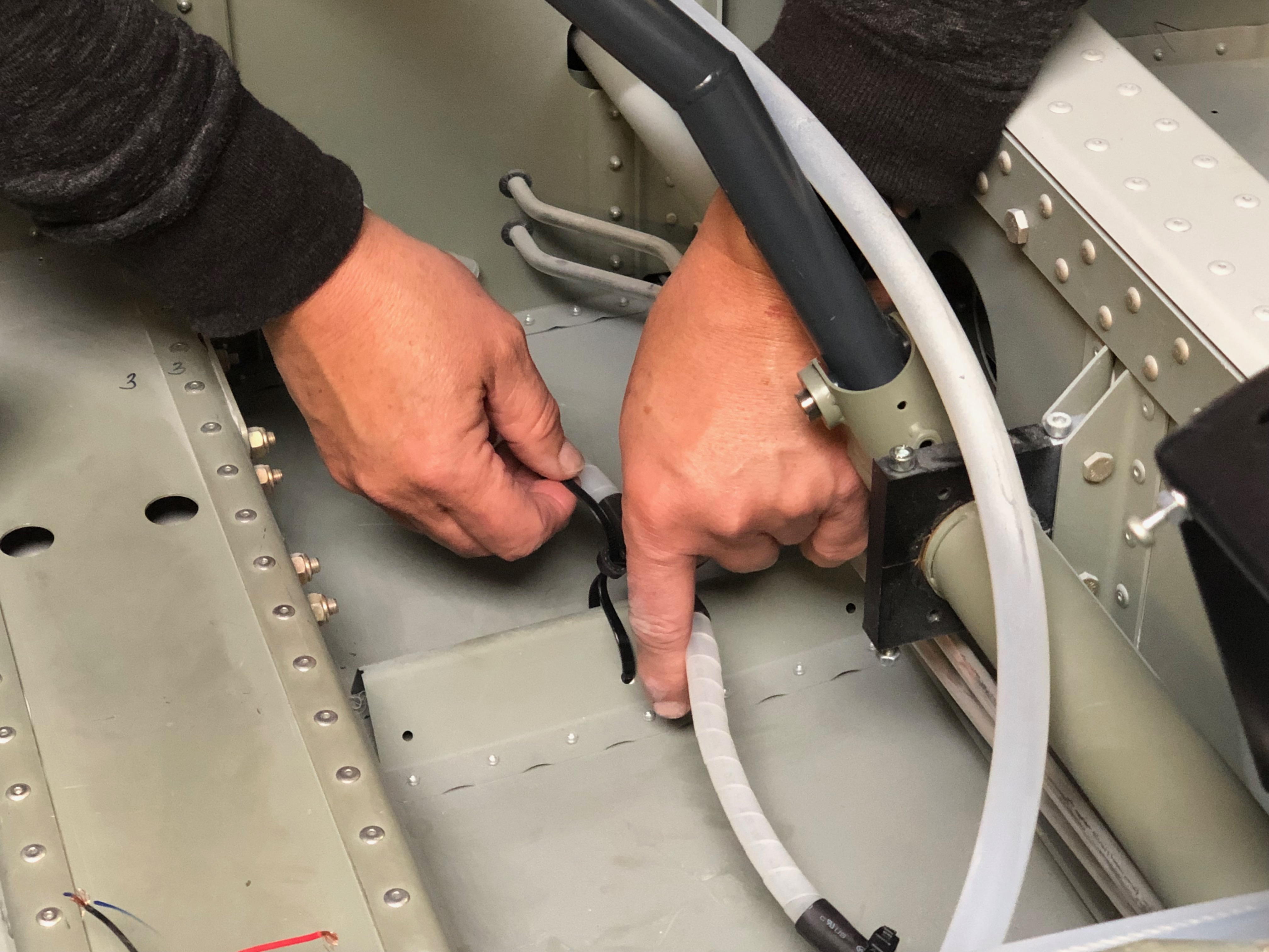
I thought it would be a good idea to cover the spiral wrap with some heat shrink tubing to protect the hydraulic pipes as it emerges from the fuselage and runs down the first part of the landing gear leg.
A slight change to the opening needed to be made to accommodate the extra width of the covered pipe.
The cover is slid over the pipe and secured in place with a tie wrap.
The pipe will be subject to movement when taking off and landing so the pipe is cut long to provide a loop to accommodate the movement.
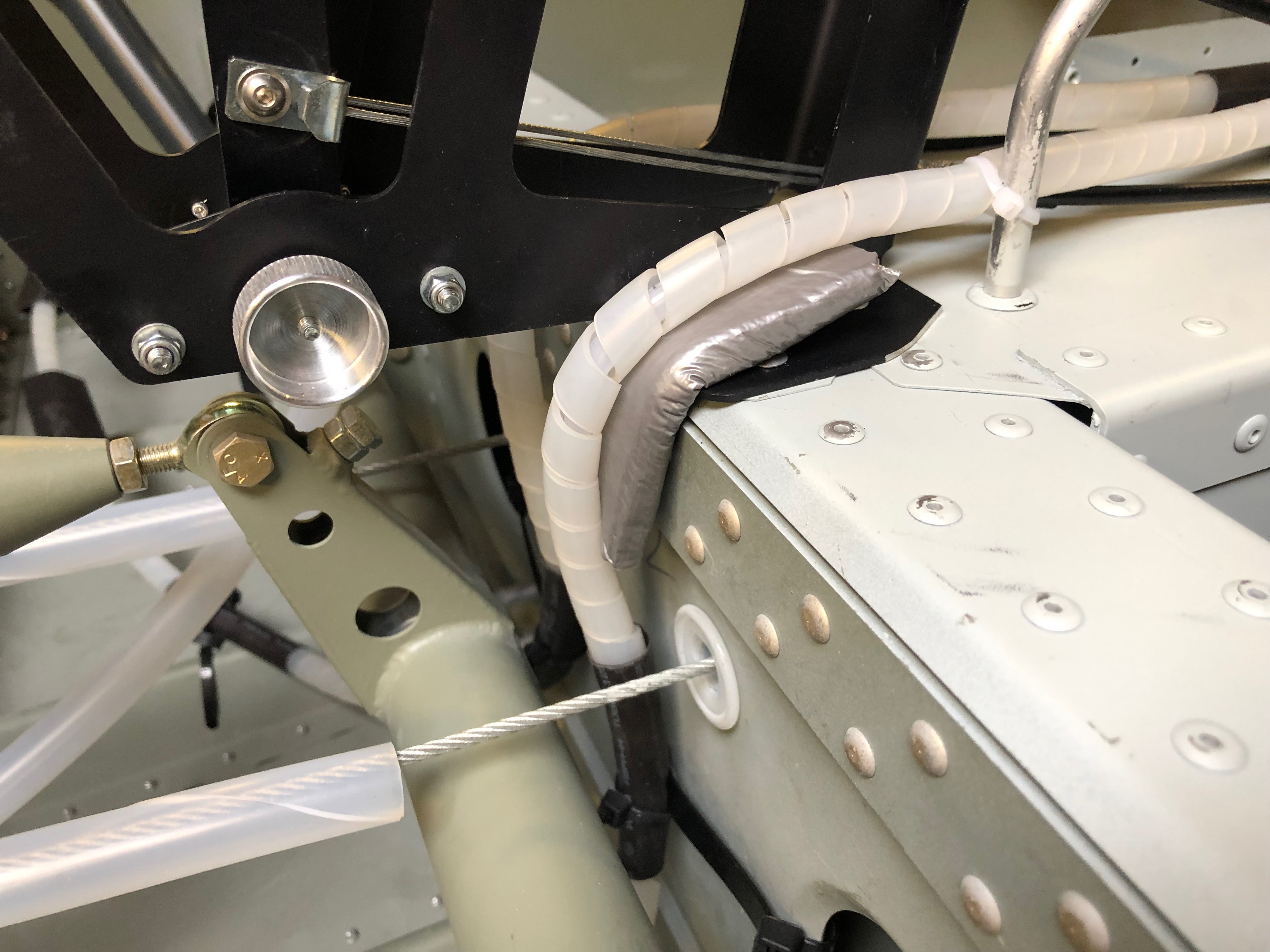
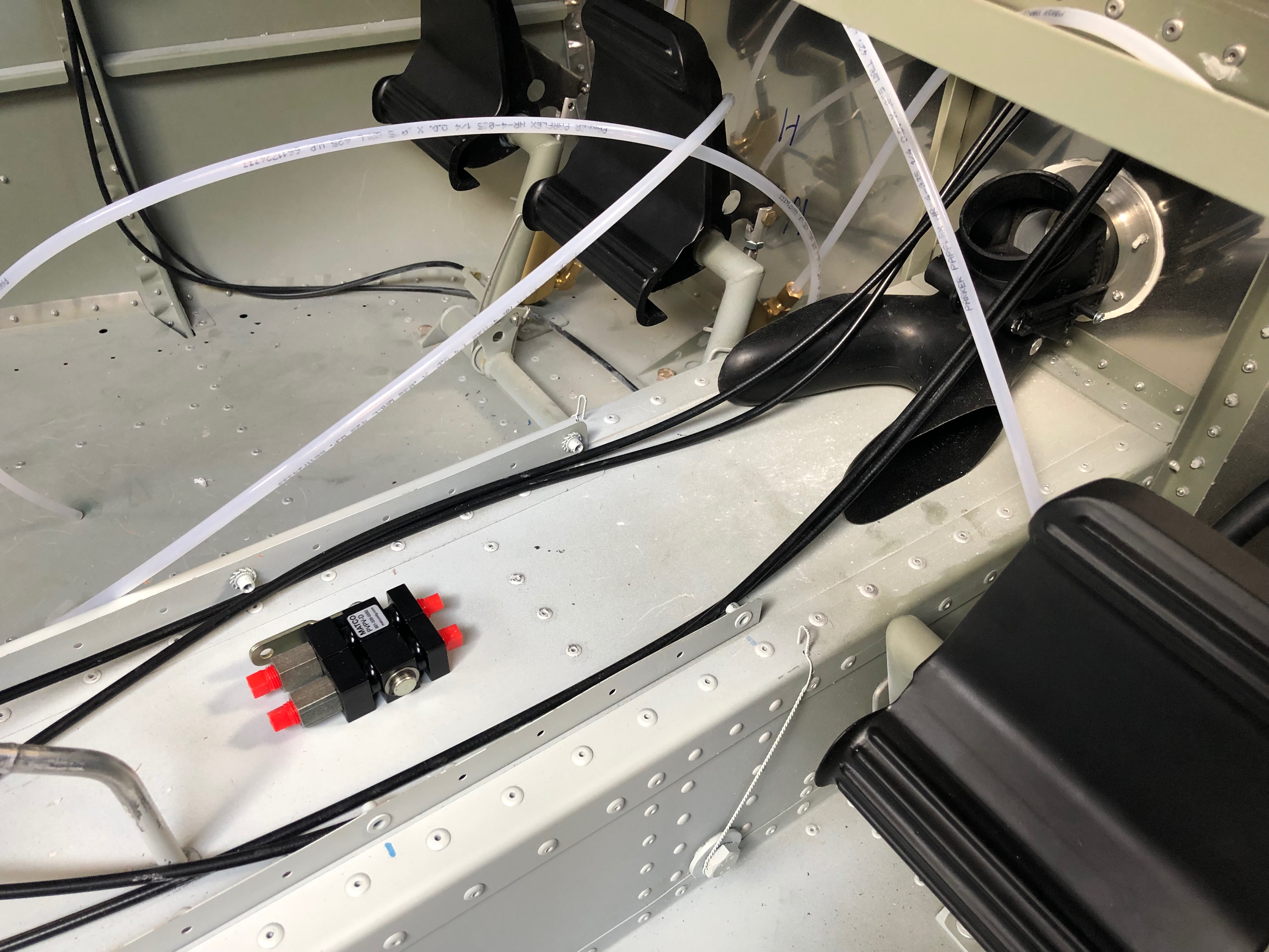
The pipe run from the the master cylinder fitting to the park brake unit looked to be under stress so I removed it, cleaned it up and refitted using a different angle which allowed the pipe to ‘flow’ better.
Before tightening the compression fittings a metal anti-crush ferrule is inserted.
The pipe run runs over a ‘sharp’ edge so I added some protection to avoid chaffing.
The pipe is held lightly in place with some cable ties.
Took much longer than I expected but the brake system is complete – at last!
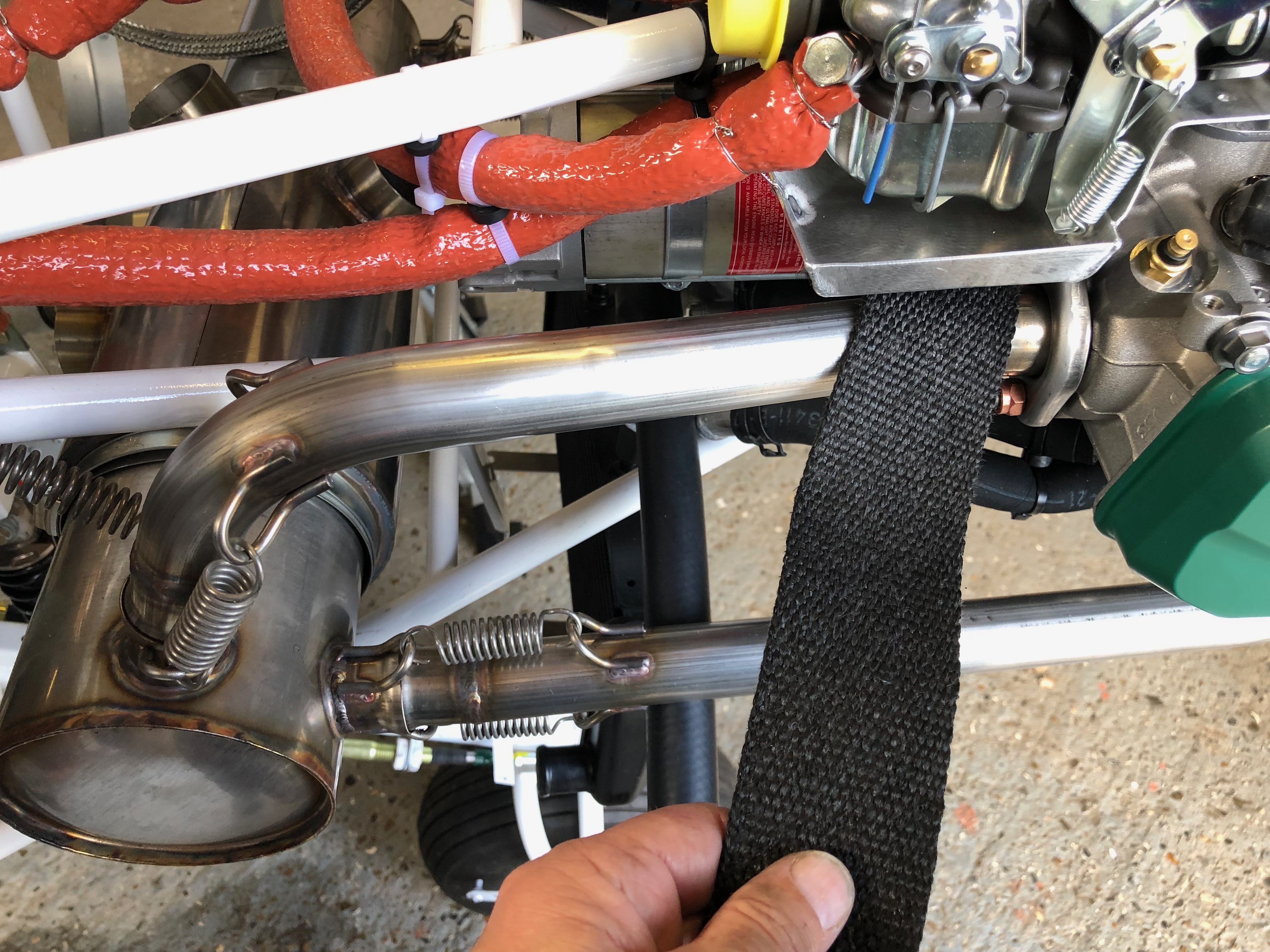
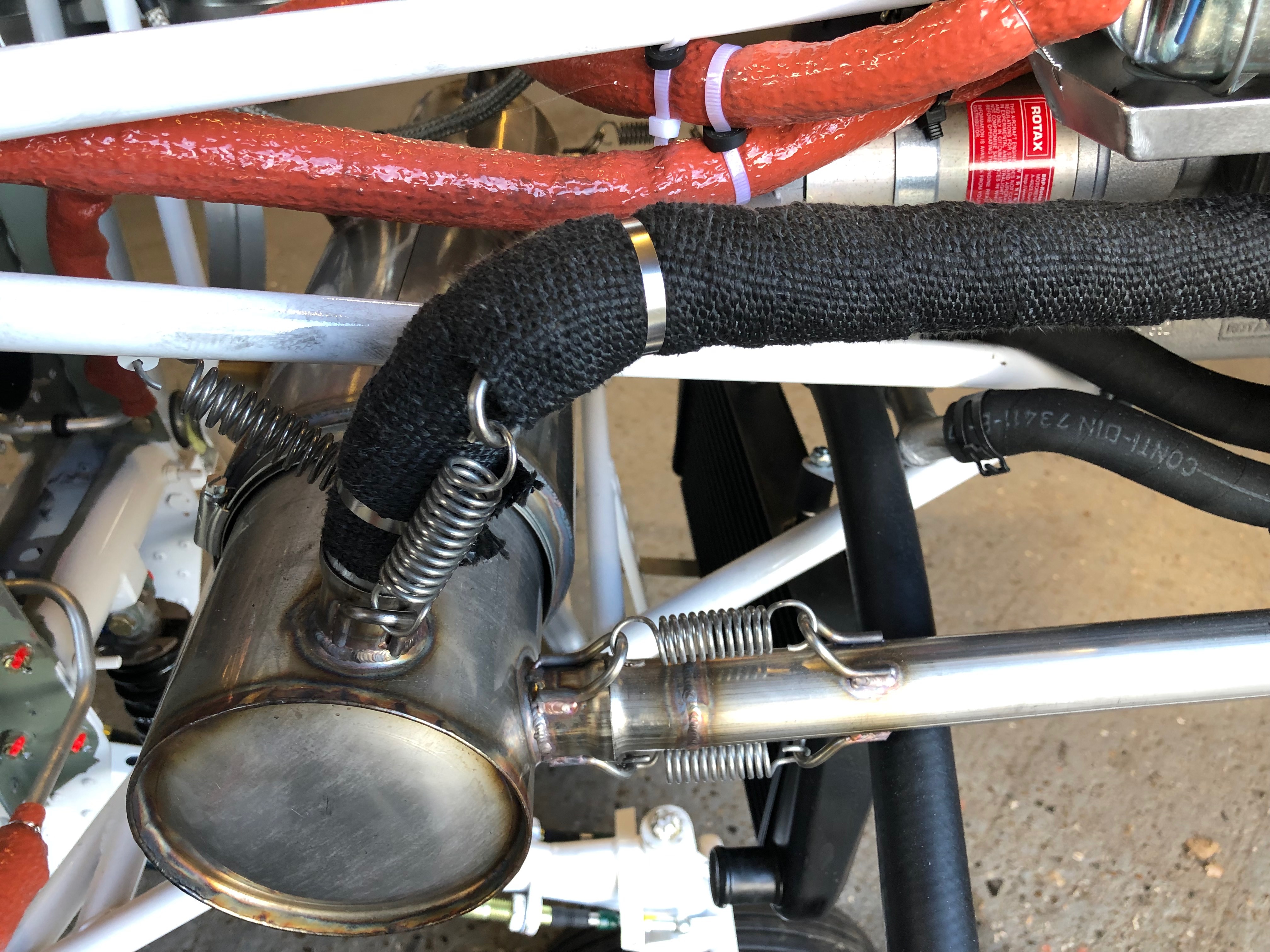
To protect the adjacent pipes from the heat of the exhaust I decided to cover the downpipes with exhaust wrap.
The starboard rear downpipes completed.
Run out of time but will take the landing lights home and fit the spade connectors as it’s a small job that can be done at home.
Karen came to help me complete the brake pipe install inside the cabin as it’s fiddly and needs a second pair of hands. certainly saved me some time.
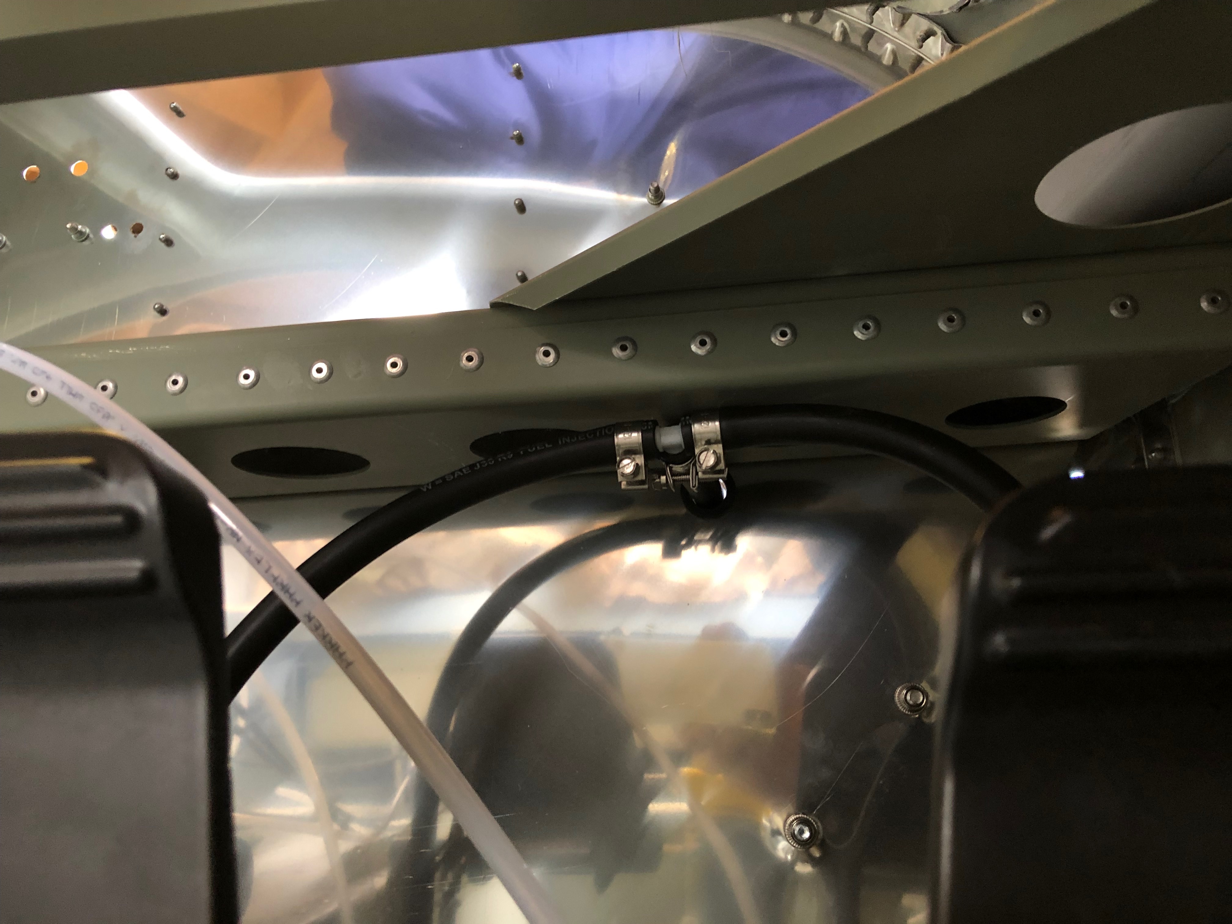
After running the hydraulic pipe to the side of the fuselage it’s covered with a protective sleeve to prevent the pipe from chaffing. I’ve chosen to use a spiral wrap similar to that used as a cable tidy but more substantial.
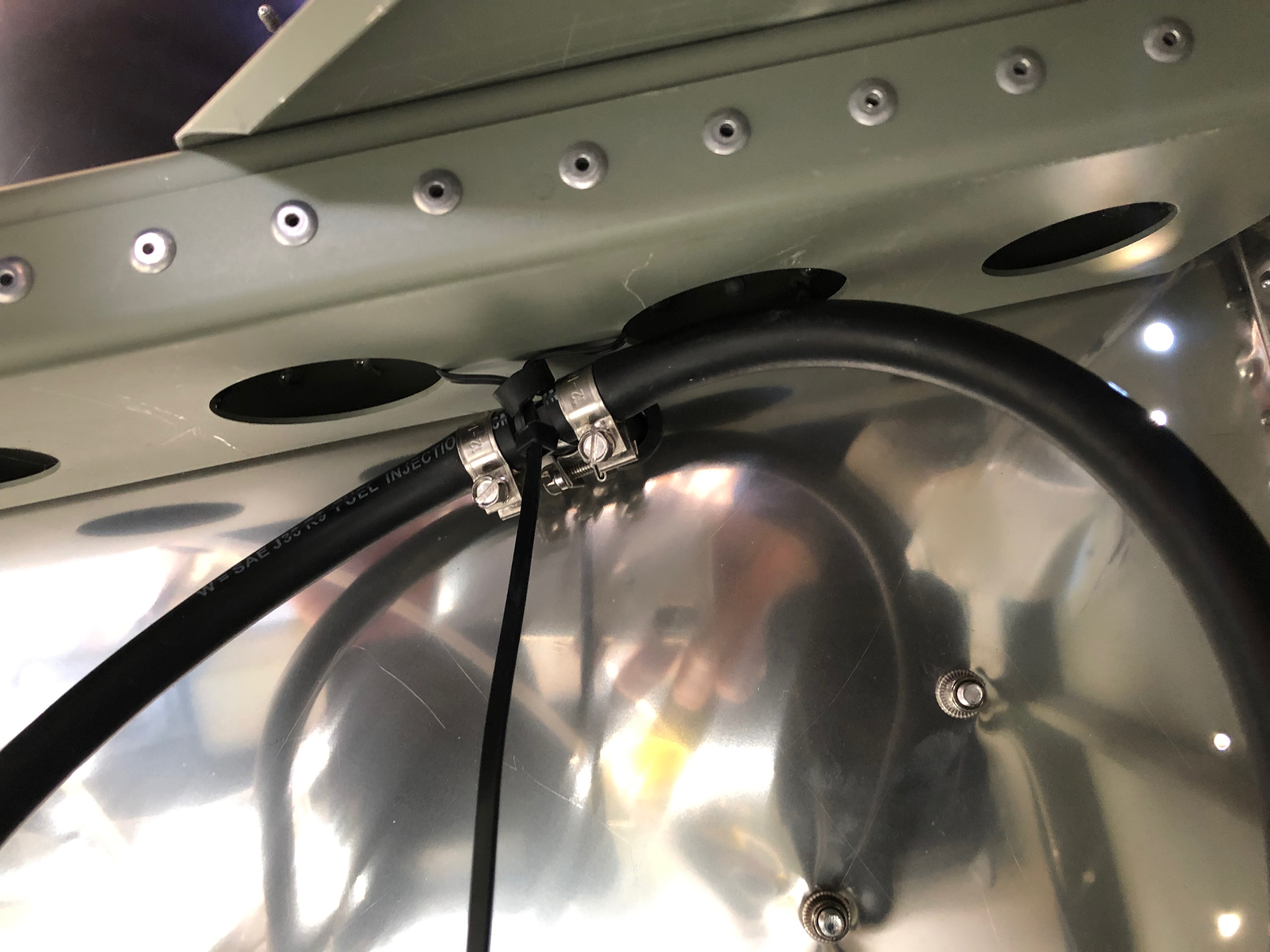
The tubing and wrap needs to be held in pace but a cable tie is likely to separate the wrap and clamp the pipe instead so I slipped some heat shrink tubing over the wrap so a cable tie holds the wrap and doesn’t clamp the pipework. Seems a good solution.
Anti crush inserts are added to the end of the pipes to stop the pipe collapsing when the nuts are tightened.
The nuts are tightened and a heat gun is used shrink the hear shrink. A cable tie is used just to prevent it moving.
Cable tie stand offs will be used to secure the pipe work onto the cabin floor. The holes are opened up with a 5mm drill first.
As I’ve said before, this job is very fiddly, you need several pairs of hands and there’s not a lot of space to manoeuvre!
But eventually it all comes together…
Installation of a cable tie stand off used to secure the pipework.
Looking at the pipe runs I found a couple of places where there is a chance of chaffing and possible pipe failure. I’ve secured a couple of pads over a sharp edge that should prevent failure in service.
A jubilant smile – it seems that this stage has taken ages to complete but Karen’s help today has really paid dividends.
The finished brake pipework in the cabin, just need to run the pipes to the brake callipers which i’ll do on Monday.
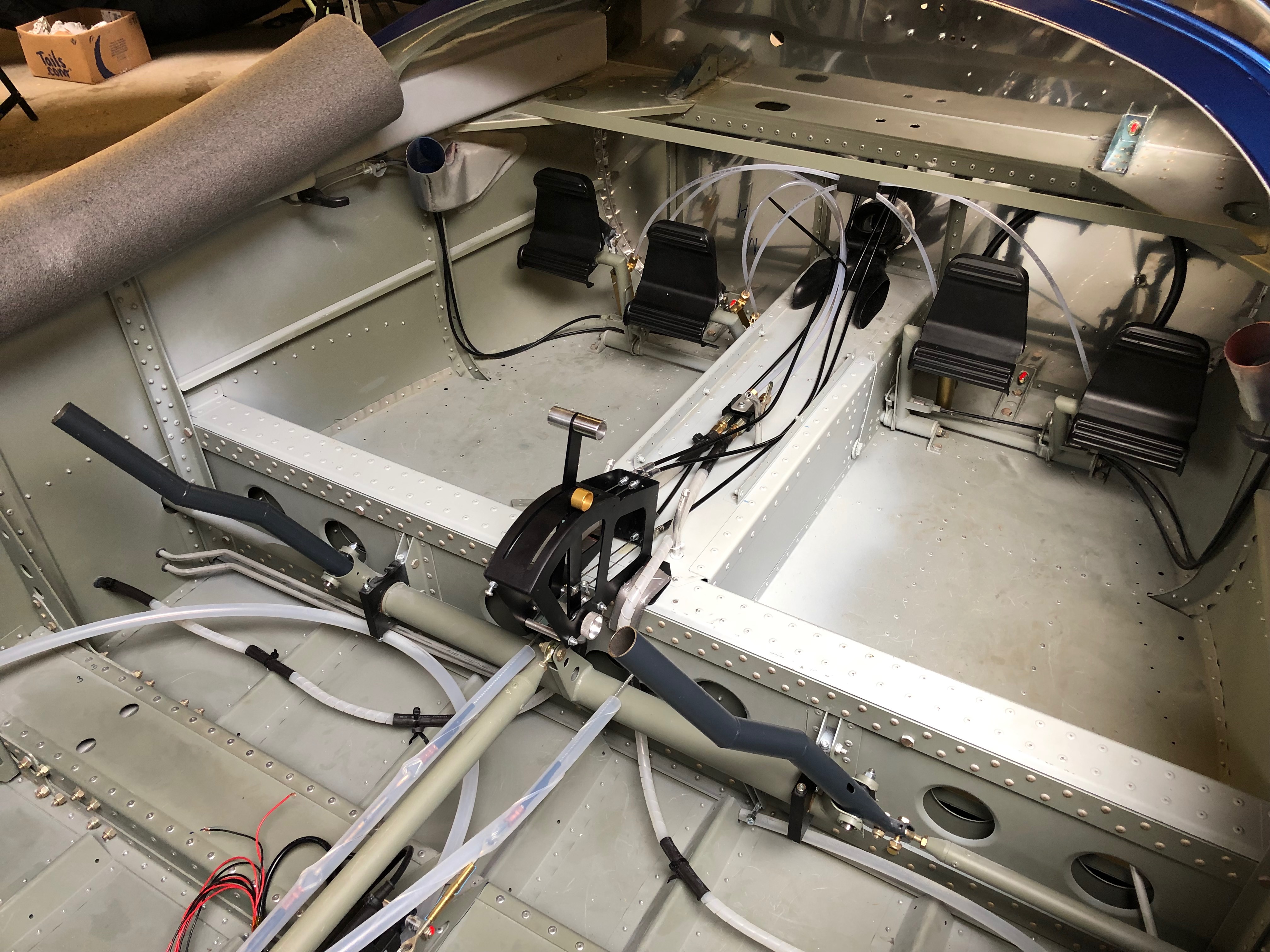
Continuing the brake system installation that has turned out to be time consuming and a little frustrating at times as the brake pipes are so rigid that they are difficult to handle.
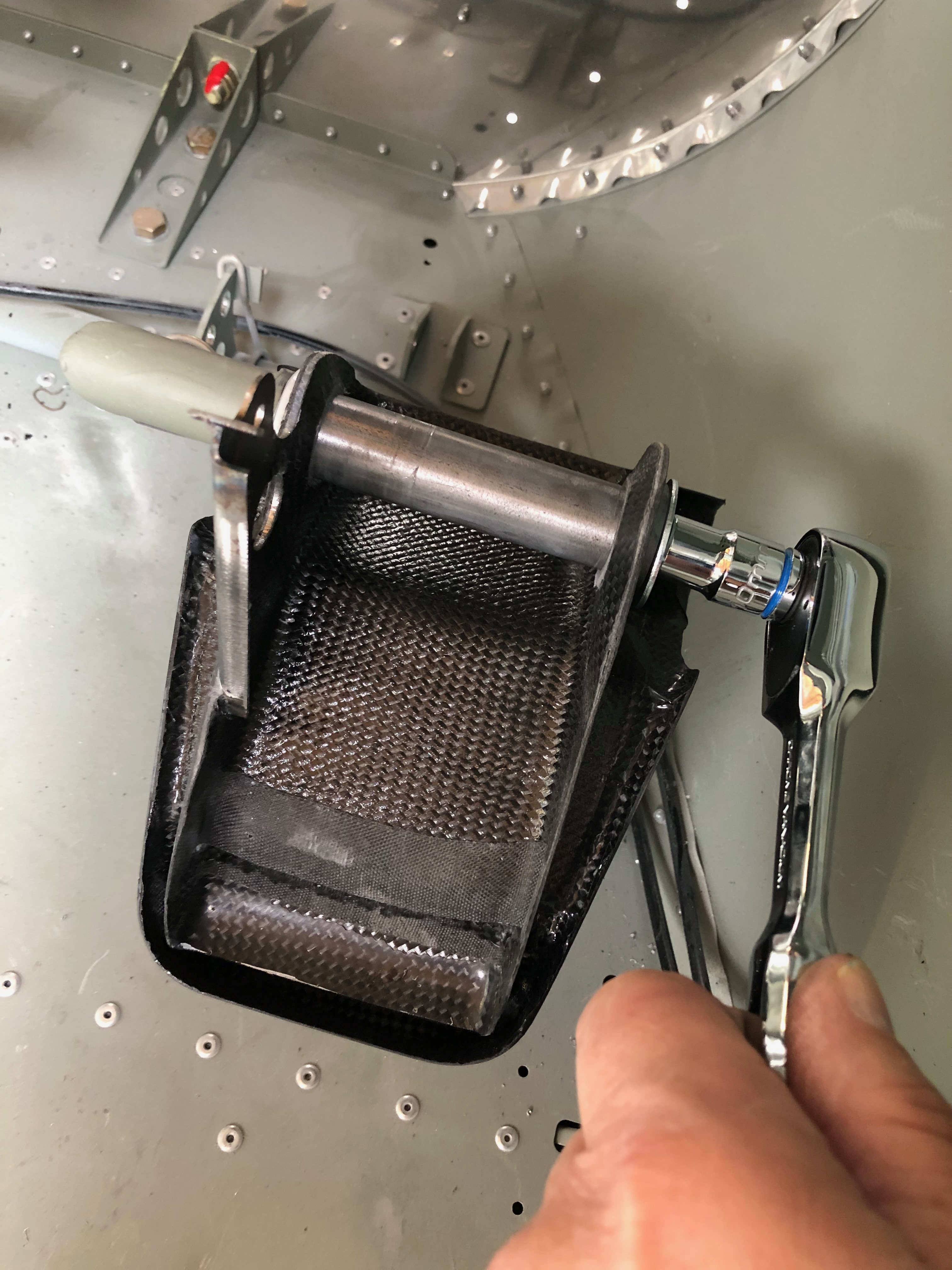
The tunnel is positioned to see how the park brake unit would sit on the airframe.
There is a service hatch on the tunnel moulding that allows you top access the pipework and park brake actuator when required.
All 1/4″ NPT brake fittings require Loctite 577 to seal the threads before fitting.
The complete unit ready for installation.
6mm holes are drilled for a couple of M4 rivnuts that will secure the park brake actuator.
The unit is sandwiched between a couple of pieces of anti-vibration rubber and an aluminium top plate and the secured with a couple of M4 x 40mm cheese head screws.
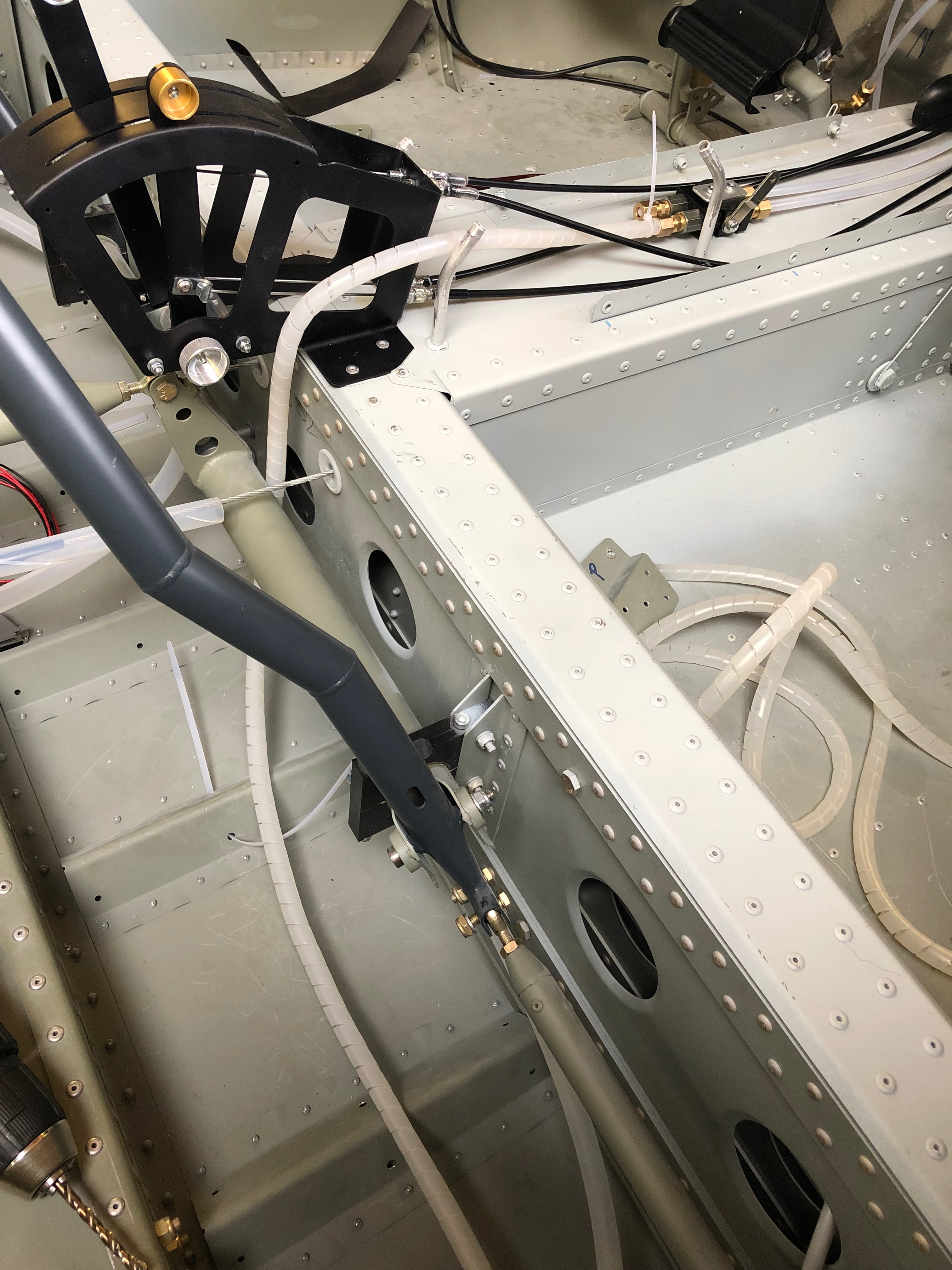
The installation so far. Such a straight forward piece of work but it’s taken ages to get this far.
Now the park brake unit is in place the pipework to the disc brakes needs to be run. The pipe is very rigid but it becomes pliable with some heat which allows it be moulded more easily.
The rigid pipe needs to be protected with a cover so I’ve used some cable spiral wrap which seems to work well.
Today’s saw a continuation of the brake system installation which has turned out to be quite a complicated, fiddly and time consuming task.
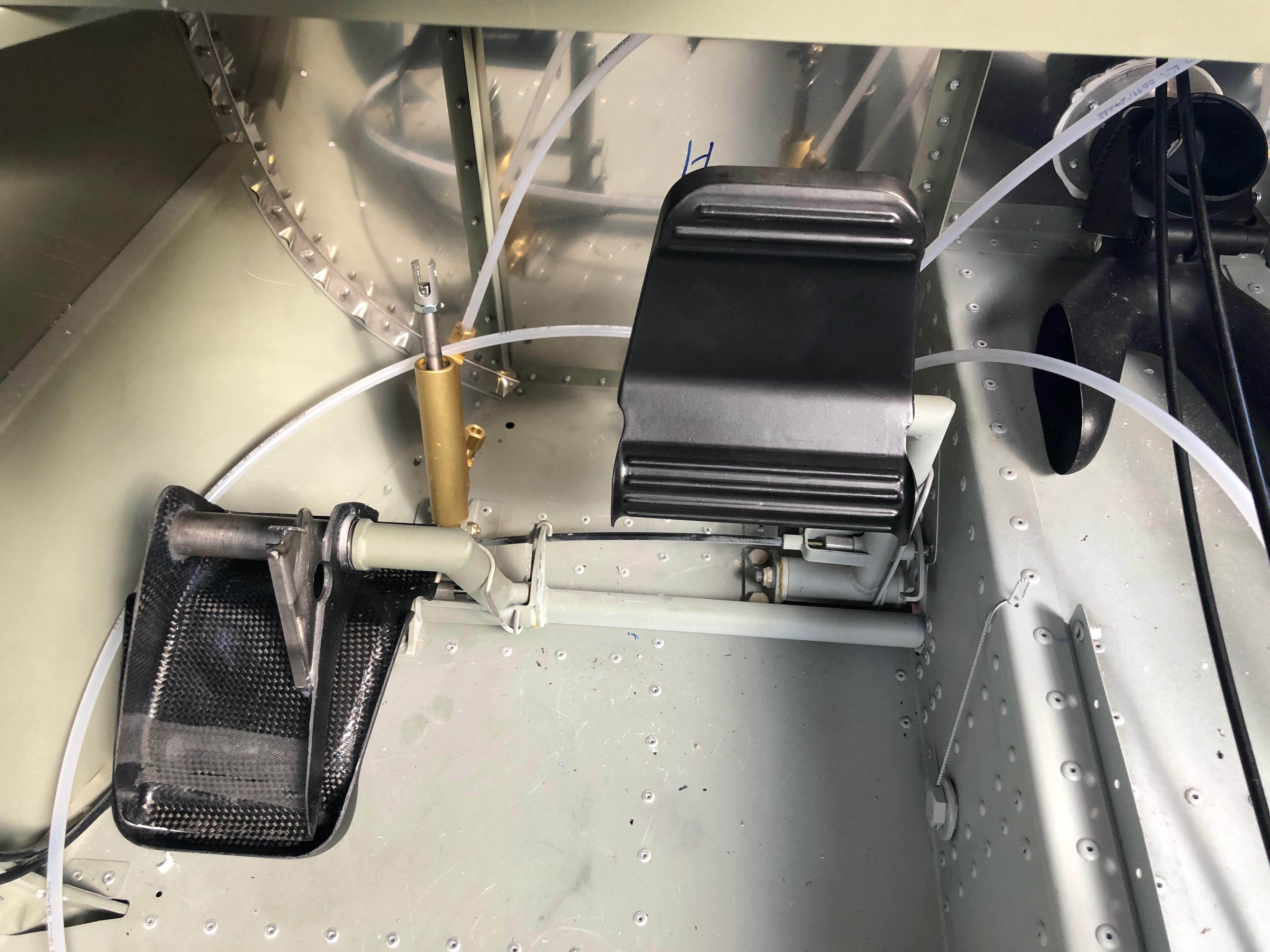
I wasn’t 100% happy with the installation yesterday as one pedal was tight on its shaft and there was slack in the top mount to the master cylinder. I decided to use a different set of washers which removed the slack and made a much better installation.
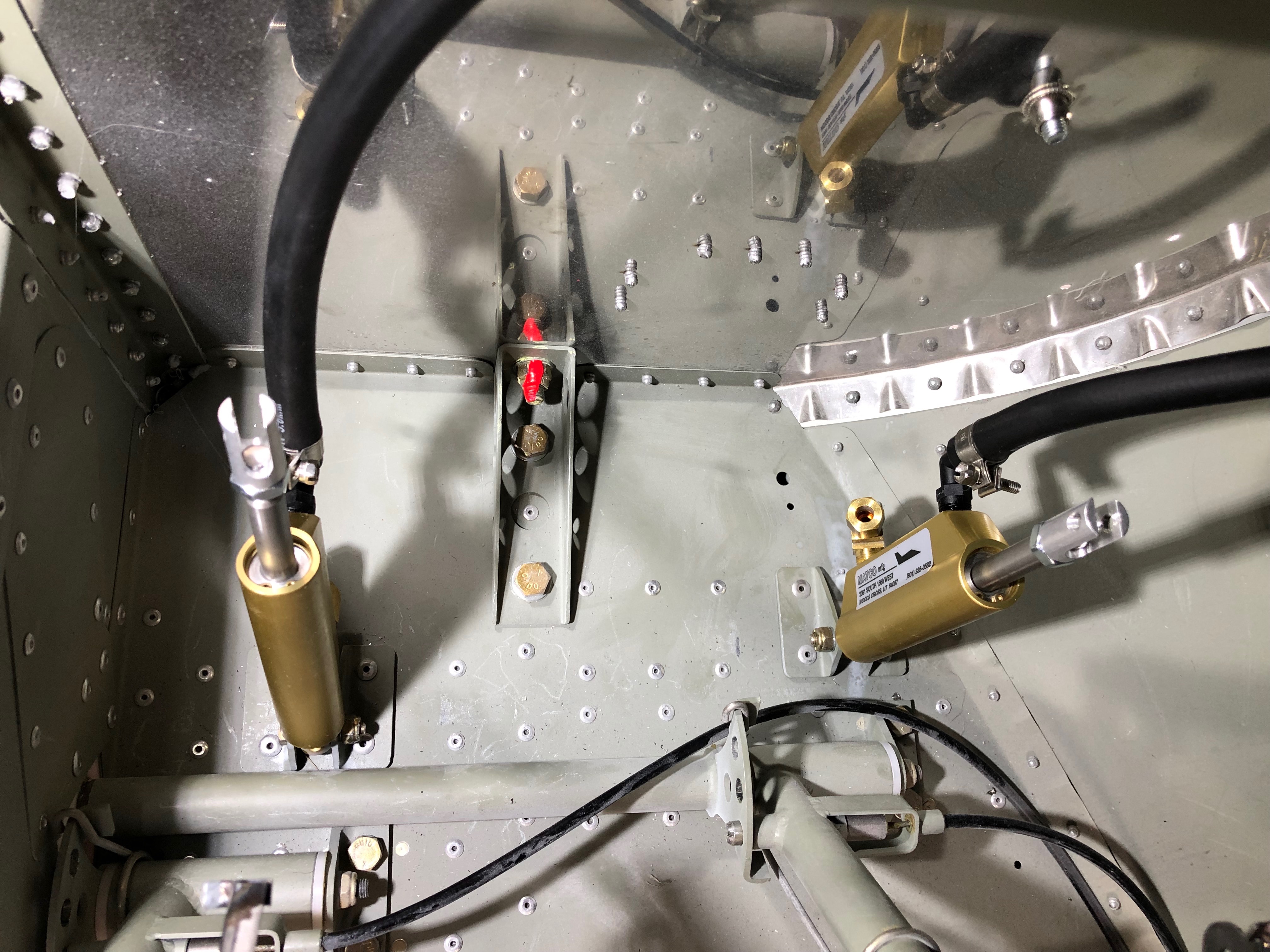
Now for the piping. The brake reservoir to master cylinder hose was installed.
A stand off is used to prevent it moving when the brakes are operated.
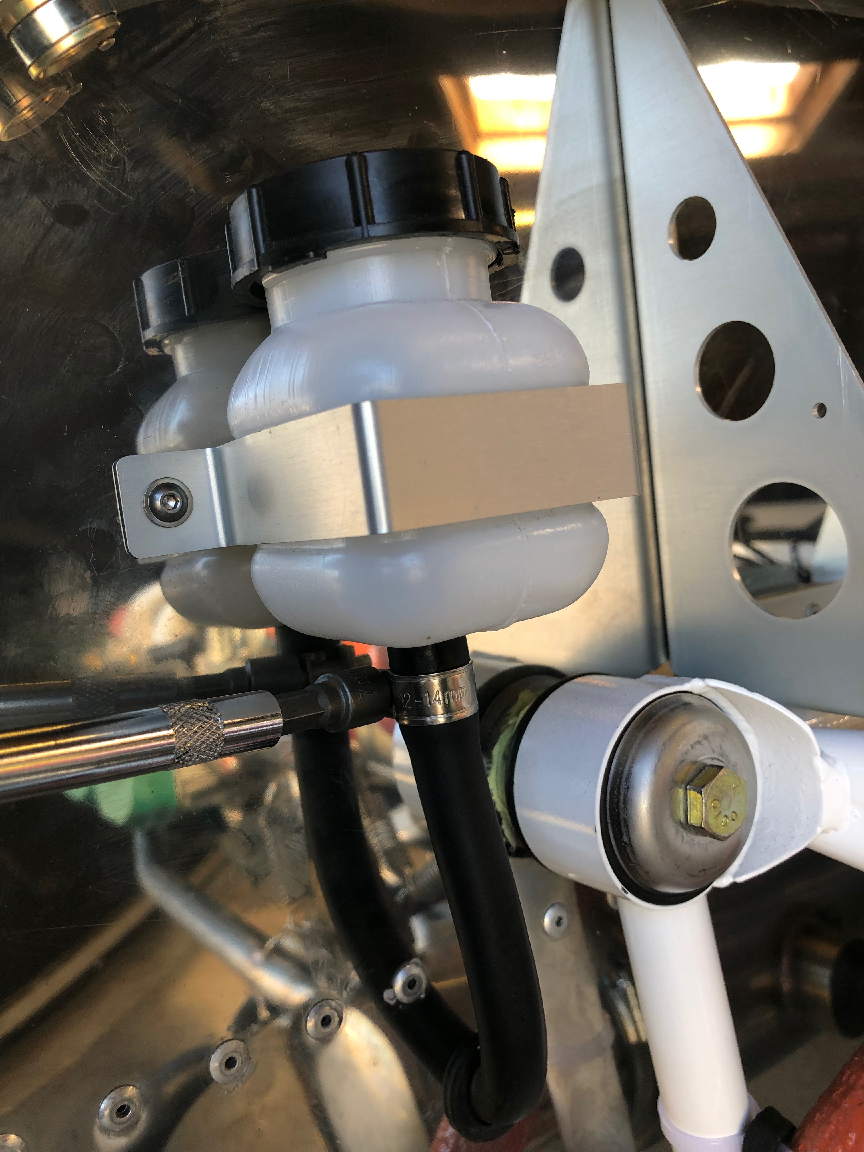
The brake reservoir bottle is connected.
The support bracket has a lining of rubber applied to make sure that the bracket doesn’t damage the bottle itself.
The bottle is clamped to the firewall and the pipe clamp is tightened.
The installation so far. Doesn’t seem much for a one and half days of work but the installation needs a lot of thought to make sure that the pipework and pedals aren’t fatiqued when operated in service.
Tomorrow’s task will be to install the park brake and the remaining brake pipes.
As I’ve now ordered the avionics for the build I thought I’d make a mock up of the panel and see what it looks like in the plane.
One of the jobs left over from the fuel system install was to fit a 1/8″ NPT blanking plug in the top of the gascolator. Luckily Ian Daniels had one spare. Loctite 577 was applied before tightening.
Next up was to start the install of the brake system. The picture shows the components that make up the system. I ordered hydraulic brakes with the parking brake option.
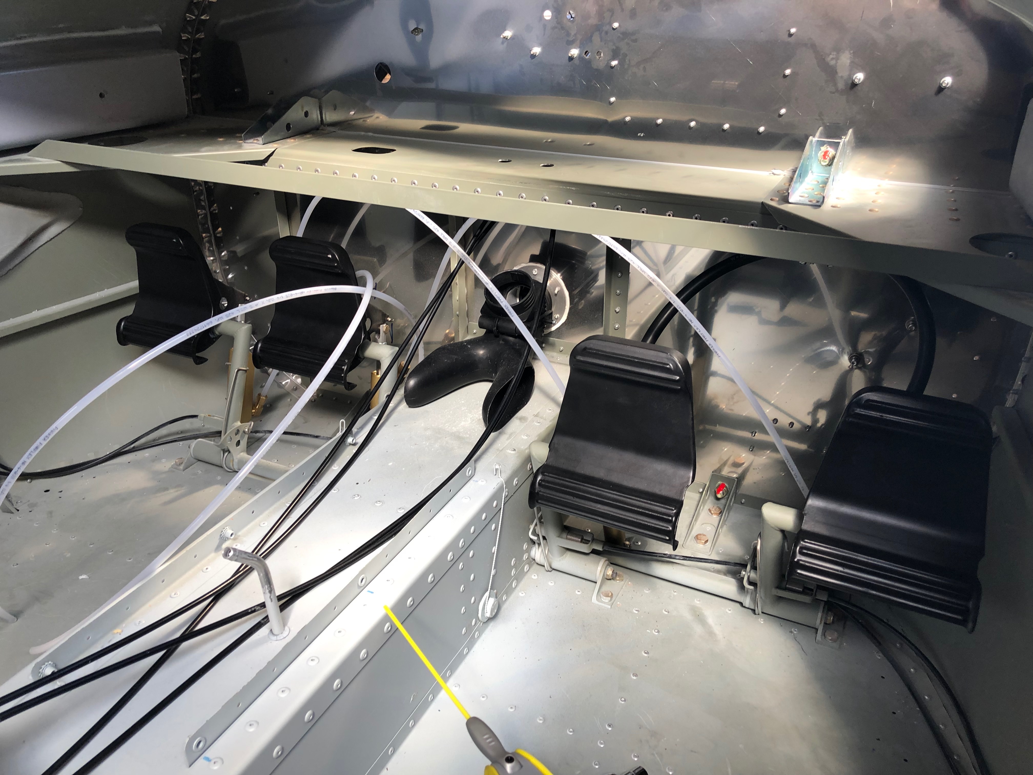
The brake sub assembly is made up outside the plane as it’s quite difficult to work in the front of the fuselage in the space behind the pedals.
The master cylinder fittings are added and threads sealed with Loctite 577.
The brake pipes are cut to size and added to the fittings to test the assembly looks right.
The brake pedals are added and secured with an M6 bolt and 30mm washer secured with Loctite 243.
All four rudder pedals in place.
The master cylinders are fitted next using a m3 bolt and nyloc.
Following the build of my Bristell NG5 Kit No. 382 Registration G-MLSY