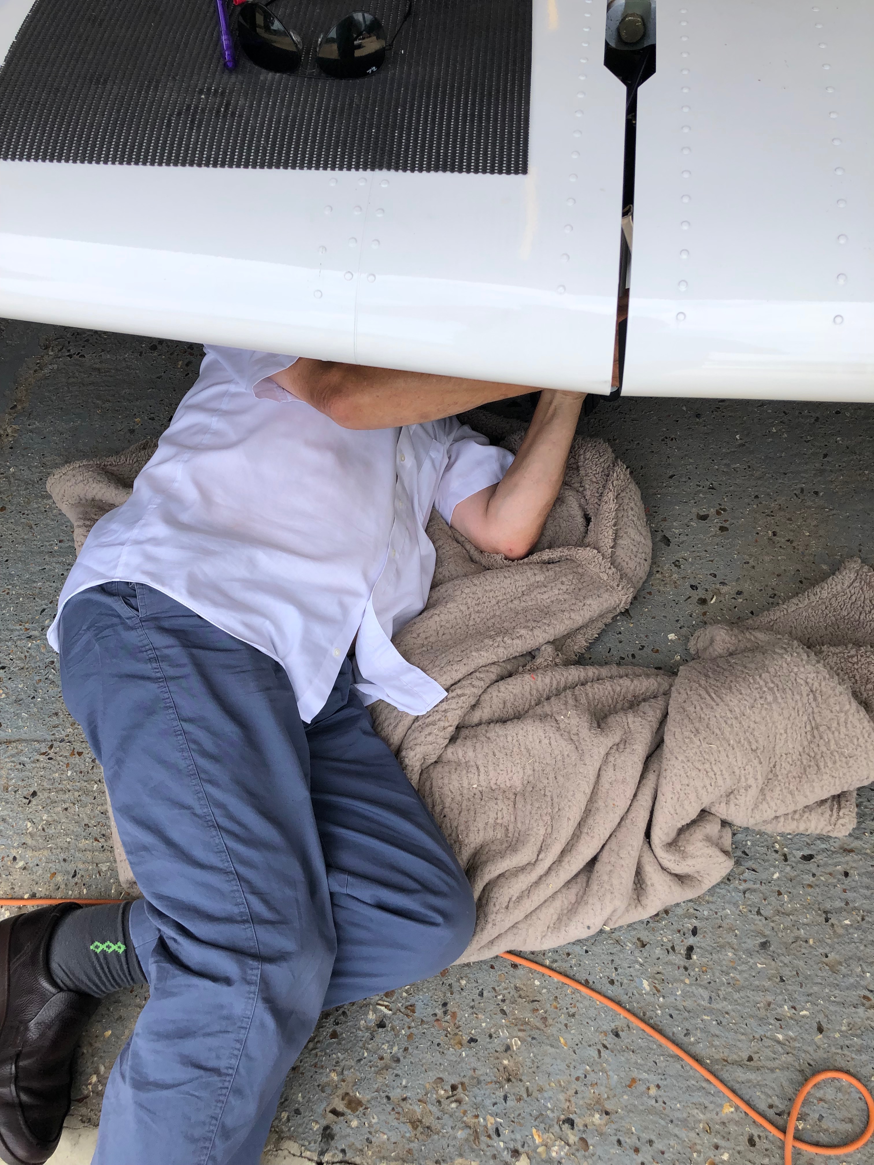
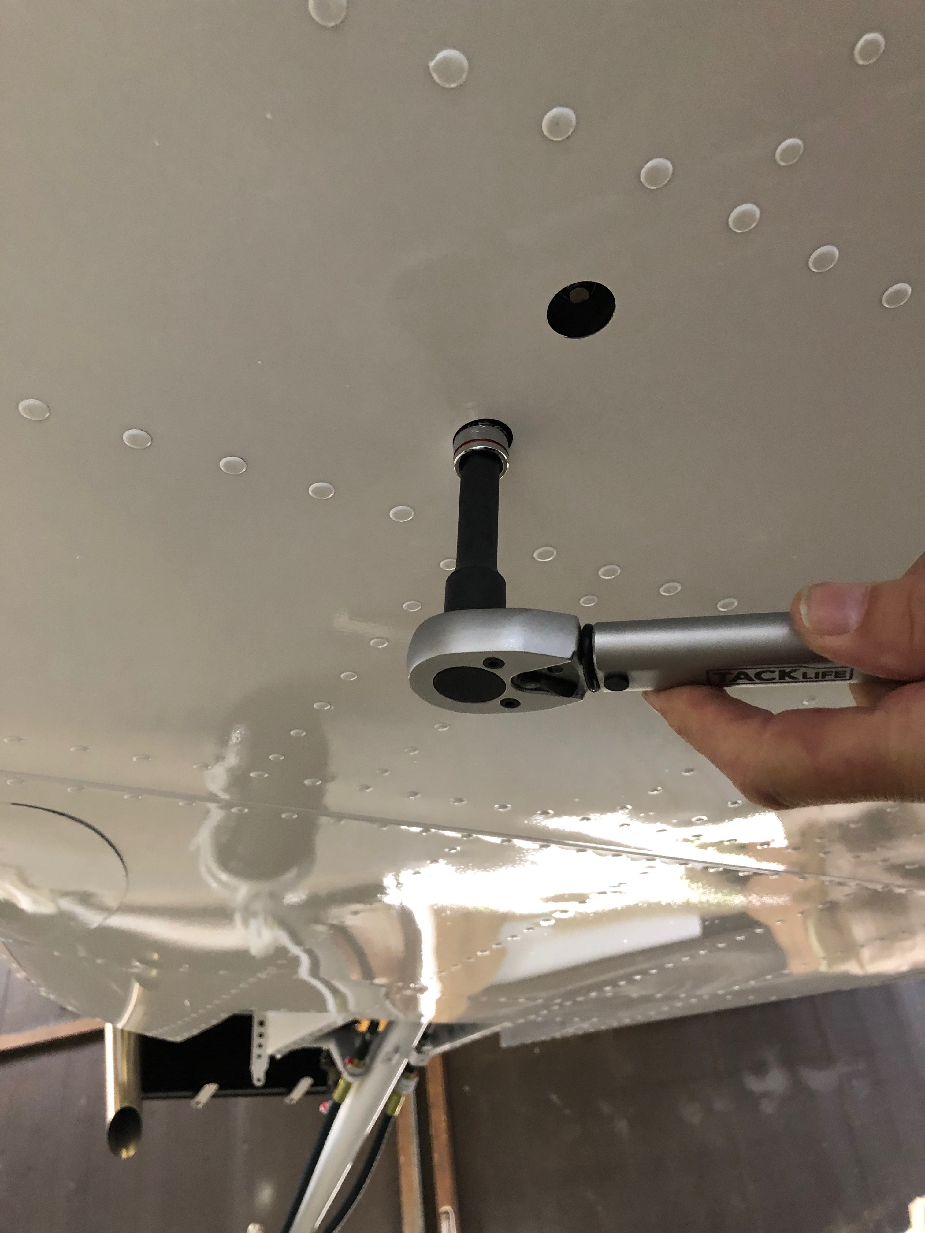
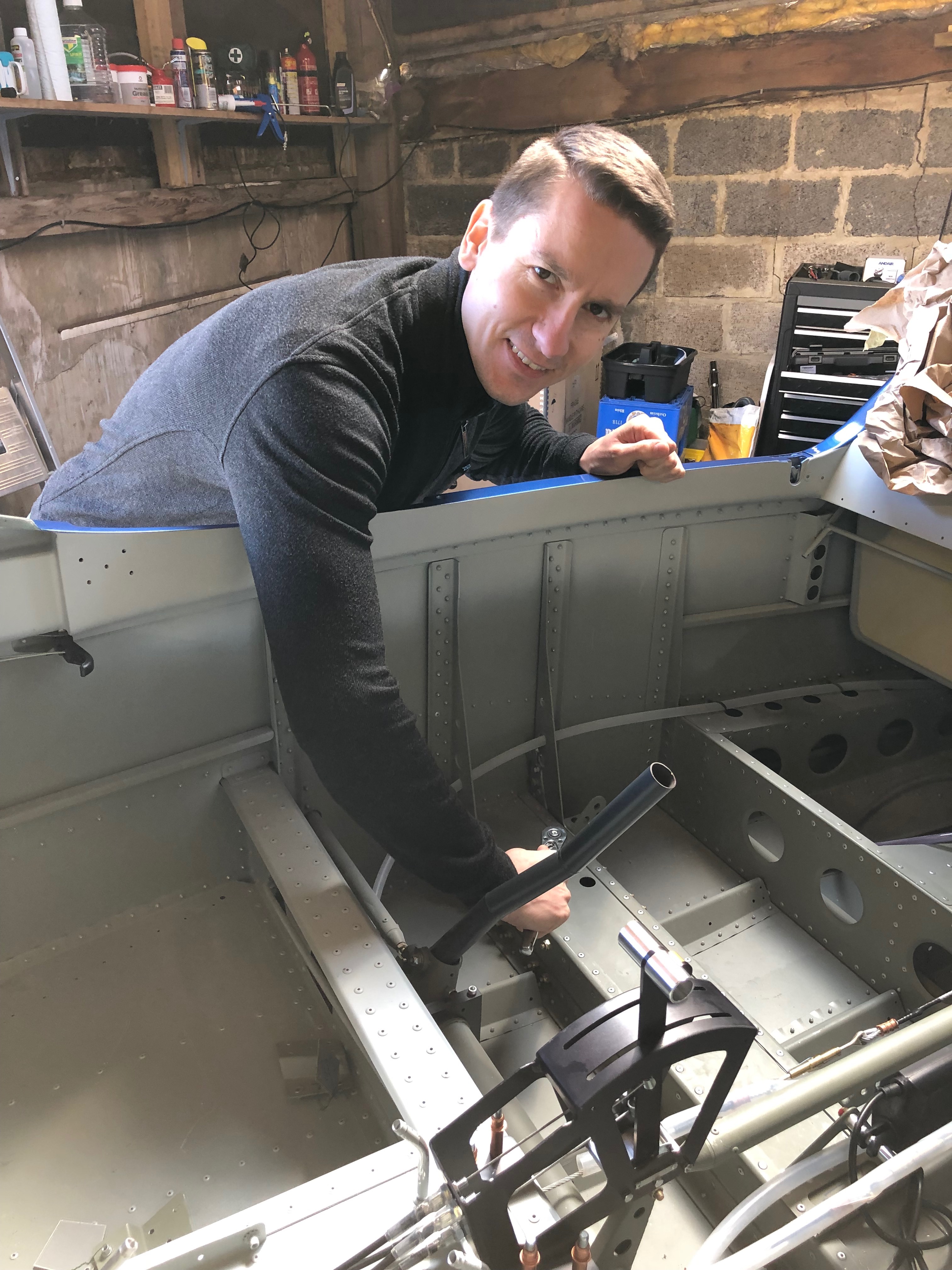
With only a few things left to do one of them is to set the control surface deflections. On the face of it, it’s an easy job but it requires a differential movement from fully up to fully down. Due to that specification there’s more than one place to adjust. It requires a bit of juggling to get it right and in the heat of Thursday it wasn’t the day to do it.
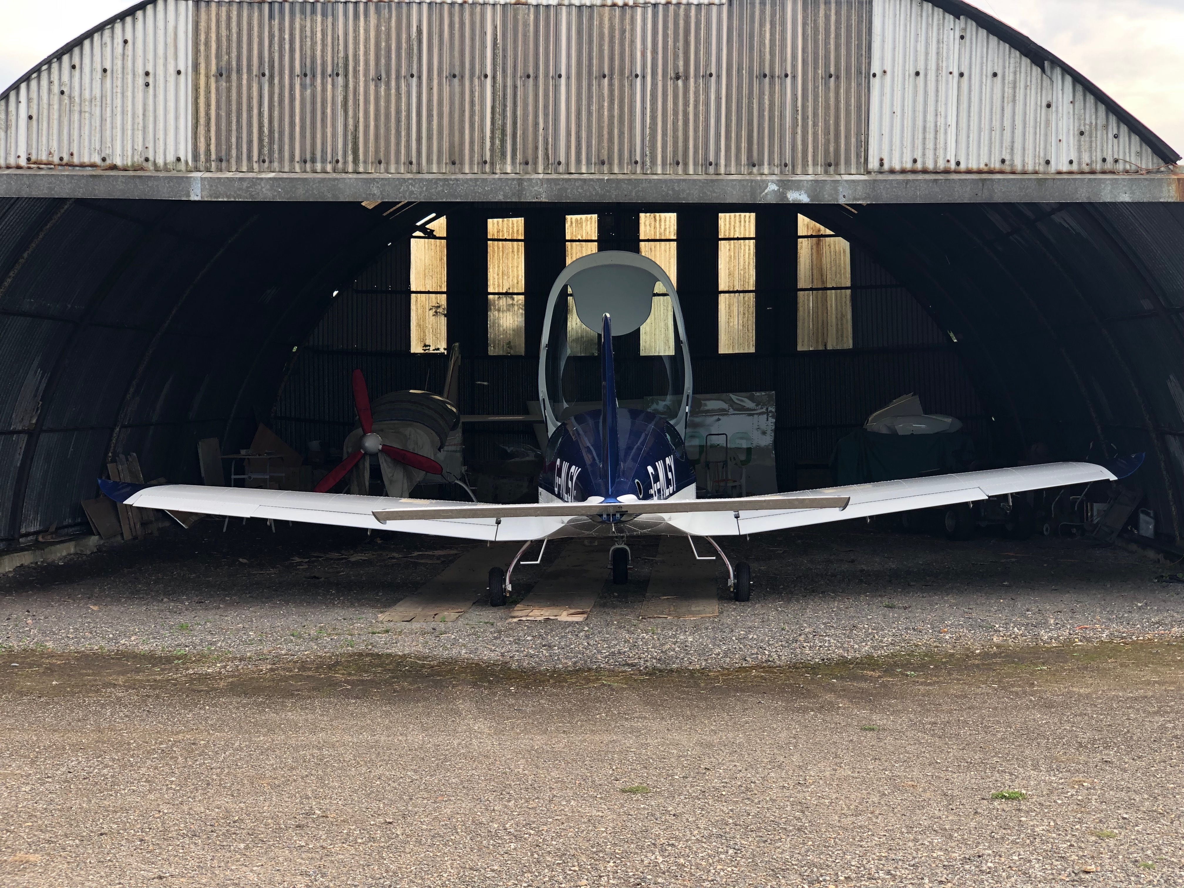
One of the adjustment points in in the rear of the aircraft with a very small inspection panel to undo nuts and make the adjustment. It was very tricky and time-consuming but got there in the end. I used an iPhone inbuilt app for the level that was then checked by Ian who has a digital protractor. Amazingly the iPhone reading match Ian’s readings +30 deg -15 deg.Ian came round to ask if I wanted to run the engine today as he’s away Monday and Tuesday. With the temperatures very much lower today it seemed a good idea so we got on with checking everything was ok before taking it out of the workshop.The workshop ceiling was far too low to fit the canopy so needed to do it once it was out. It took a lot of jiggling to get it out of the workshop and now it’s out it won’t be going back in! Out on the grass away from all the stones and Pete Sharpe recording the event on my iPhone it’s time to do a final check before the first start. The electric fuel pump was switched on to check for leaks from the fuel system, all seems ok. First time in the cockpit for real so another good check to make sure every thing is working as expected. Ian is standing by just in case anything goes wrong with a radio and fire extinguisher!Canopy down, calling “CLEAR PROP” as I turn the ignition key and my baby burst into life on the very first turn – I can only shake my head in disbelief – Amazing!Watching the Ts&Ps as the engine is running Ian does a walk round to check for any obvious problems but there aren’t any. It’s running as sweet as a nut.After being told to smile I look up as one happy chappy… Ian prompted me to taxy the aircraft to spread the noise about a bit so I did a few runs up and down the runway checking brakes, steering, instruments, pitot system and then power checks. All very good apart from the flys on the firewall. Ian carried out a further check once the engine had stopped but all was ok and there were no problems.A very empty workshop. It seemed big enough when I first started but as time went on it proved to be too small to house the aircraft on a permanent basis.So this is where G-MLSY will be for the weekend before being moved to its new position in the main hanger.
A number of jobs planned for today. Complete the engine NACA ducting, install the clevis pins to the carb heat control and cabin heater, install the fuel pressure sensor, install the engine intake air box, install the MAP sensor pipe, adjust and set the cowl quick release fasteners and install the control stick torque supports.
The fuel sensor and adapter were left to set with Loctite 577 overnight so can now be fitted to the fuel hose that I had added for it.
The hose is secured with a hose clamp and fire sleeve is added which is secured in place with locking wire.
The sensor is secured against movement and vibration with a stand-off.
These are the clevis fittings that are used on the carb heat, cabin heater, screen de-mist and park brake.
Now the sealant is set, the air box is mounted on a couple of brackets off the engine mount. It’s secured with a couple of Nyloc nuts underneath. Two short pieces of sturdy rubber hose are fitted over the carburettor inlets and the air box and provide a flexible joint between them.
They are secured in place with jubilee clips.
The SCAT ducting is secured in place with jubilee clips to the air box intake and the starboard lower cowl side NACA duct.
The ducting to the port NACA duct is run to the rear of the exhaust and then into the centre inlet on the heat exchanger, secured with jubilee clips and held in position with a couple of tie wraps.
Port NACA duct.
Even with all the space that the Bristell has It can get a bit tight with all the hoses that are required.
The MAP sensor has already been mounted so just needs a pipe to be run and of course some wiring at a later stage…
I’ve used 5.6mm ID R9 fuel hose between the carburettor balance pipe and the MAP sensor.
The quick release fittings on the fuselage have been riveted in place and now require them to be adjusted and set. First thing is to screw them in…
until they are flush with the cowl.
Once adjusted the pin can be pulled that sets them into position.
They are released by a quarter turn of the Philips screw and the fitting stays set in place.
I still need to repeat the process for the top cowl and the oil inspection cover. Ian will be installing the fittings during next week. Unfortunately the rivets need to be ‘squeezed’ and I don’t have the tool to do it.
Now I’ve picked up the control stick torque arms I can start work on the control sticks.
The fittings need to be checked and secured although they will need to be adjusted when the wings are fitted to centralise them, set the limit screws and check aileron deflection are correct.
The torque arm is attached at one end using the bolt from the control stick bearing.
The other end is secured with a 4 x 15mm rivet.
Both torque support arms fitted, completing a fairly productive day.
I’m still not 100% sure on the layout of the screens and associated control panels so I thought it would be good to add the pilot seat so I could check different layouts.
Once the seats were installed I could sit in the aircraft as I would normally fly it. The panel here has most of the bits I need but is missing the flap switch, some warning lights and the air vents.
I’ve stuck the pictures on using glue dots that allow me to move the pictures about. I can then do a ‘touch’ test on the layout to see what works best.
After some exciting skiing in Val Thorens it’s back to work. Whilst I was away I planned my weeks ahead based on what’s left to do. Some small jobs to get me back into the groove.
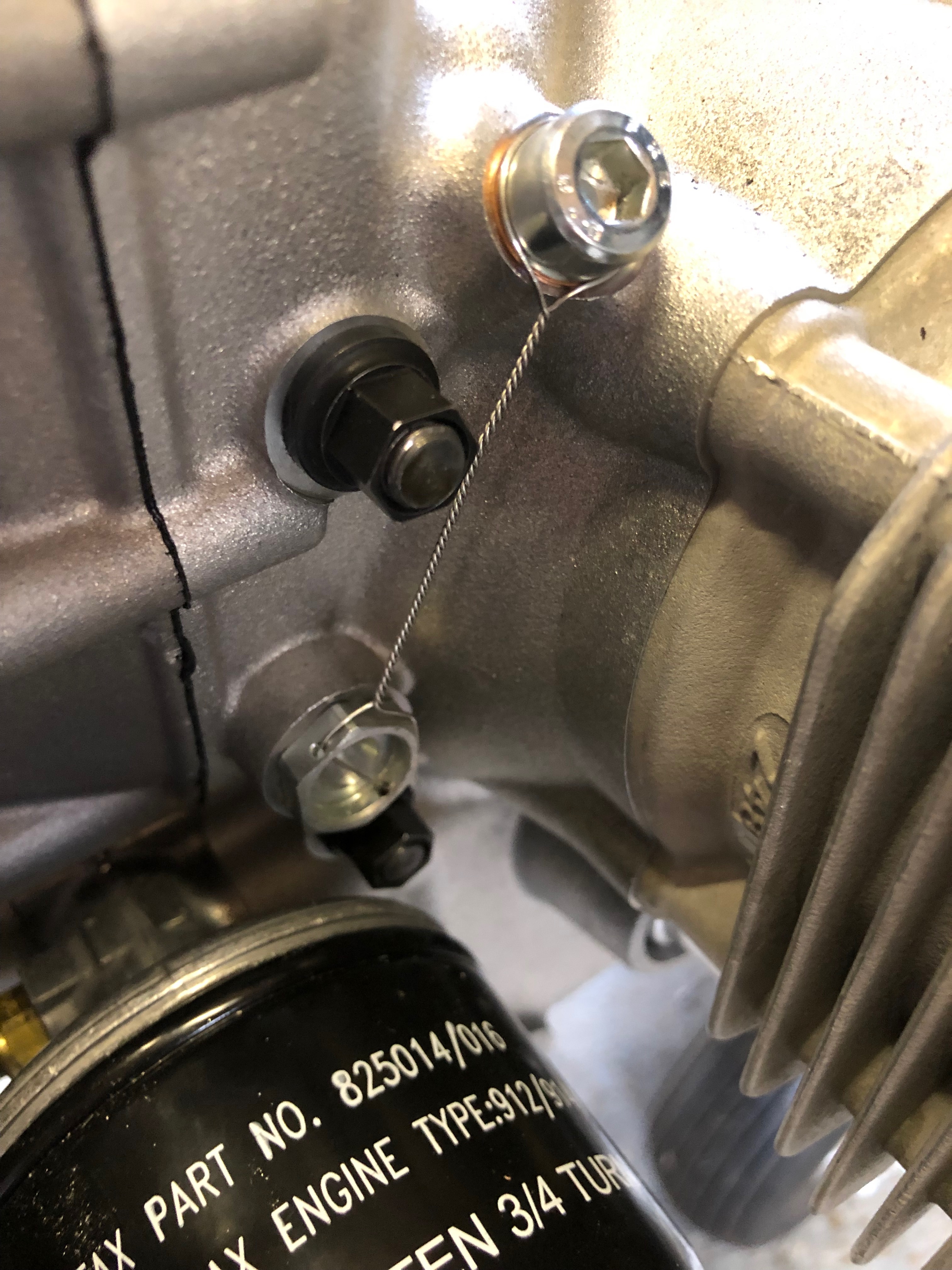
The magnetic oil plug needs to be checked for debris. If any large pieces of metal are stuck to this it’s an indication that there is a problem with the engine.
Once checked the plug is refitted and locked to prevent it from coming loose whilst in operation.
The oil drain banjo underneath the engine also needs to be wire locked.
A job leftover from fitting the canopy locks is installing the centre canopy release mechanism.
Holes marked and drilled.
A rivnut is installed and the mechanism is secured. Once the interior panels are fitted the operating wire will be fitted.
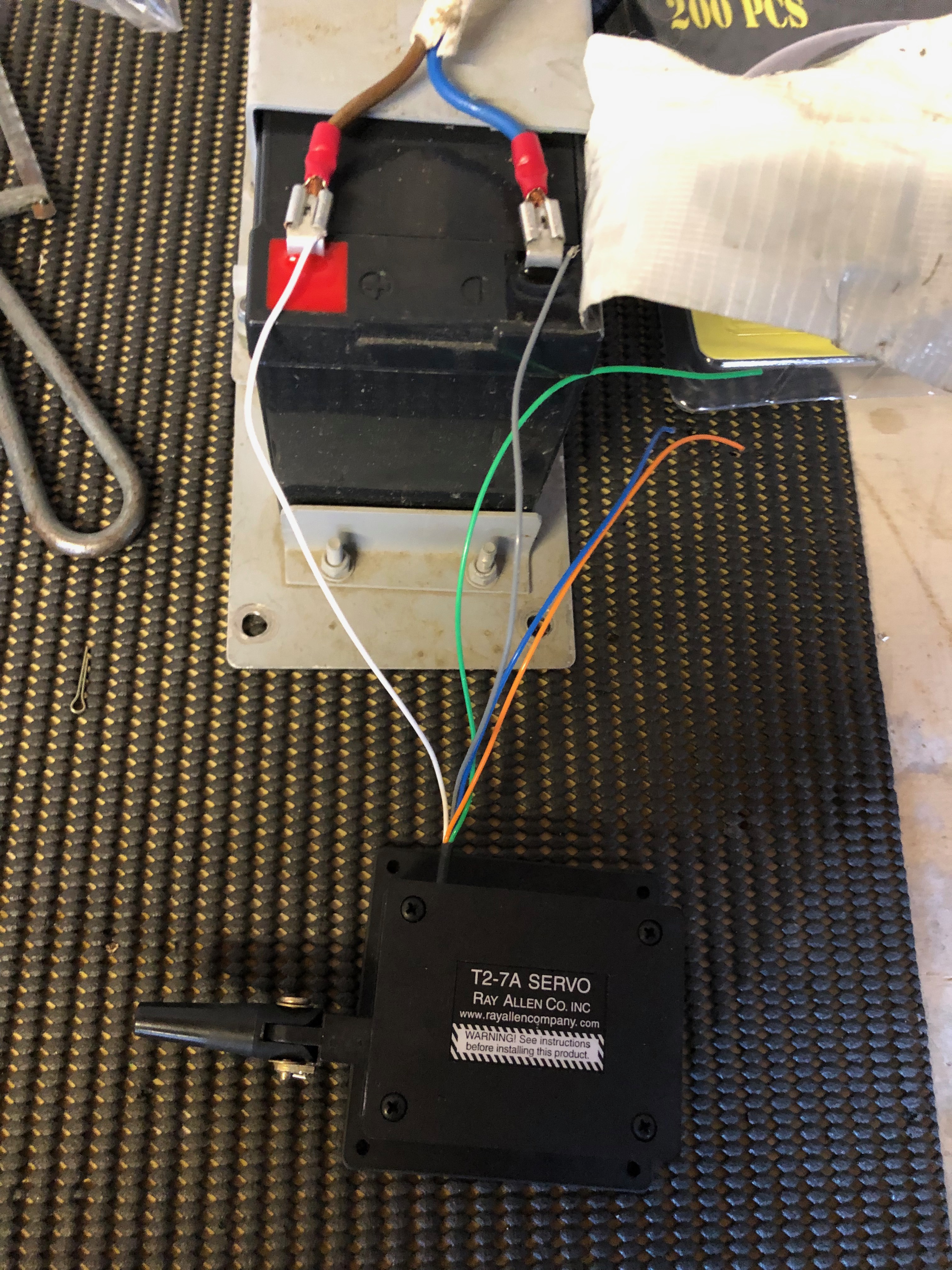
When Chris came down he helped me install the electric aileron trim servo. Now it’s time to install the Elevator trim mechanism. Chris had already attached the clevis, pin, split pin and had cut the threaded rod which cuts some of the work I have to do.
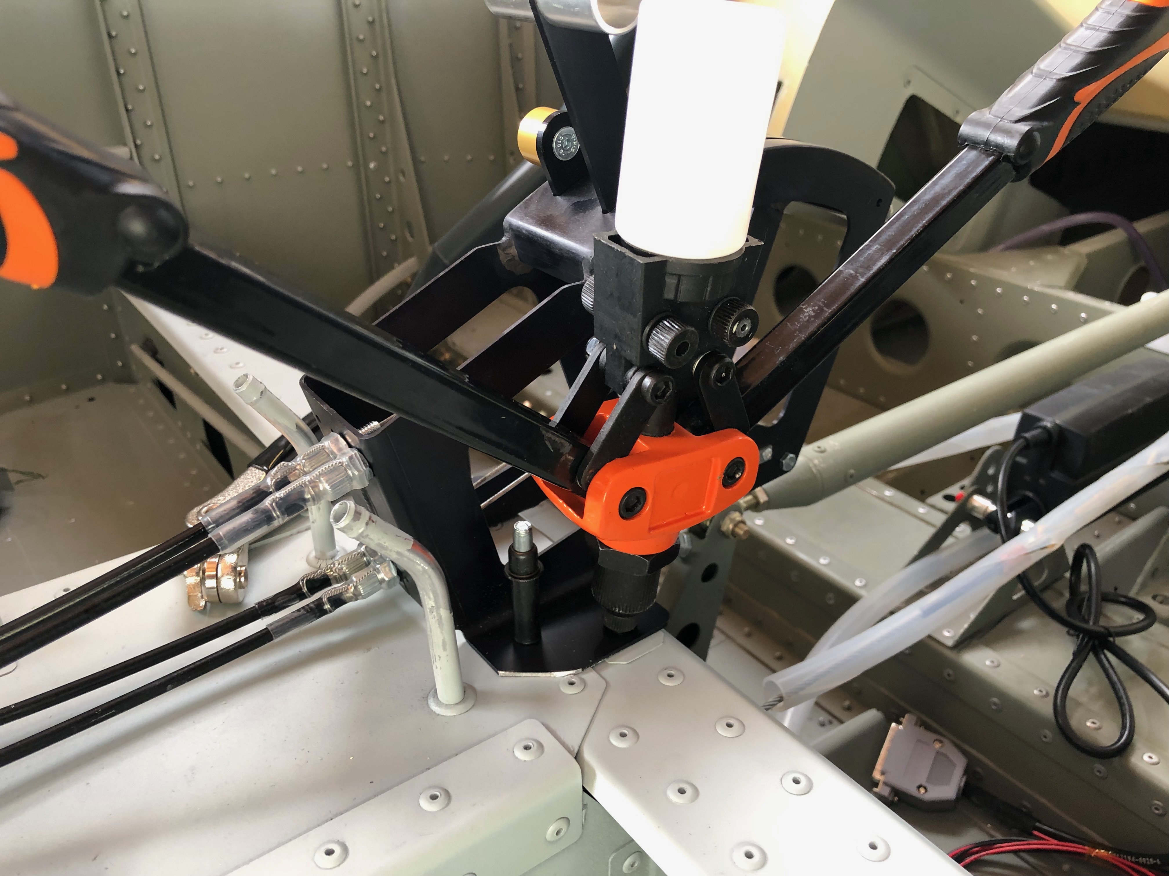
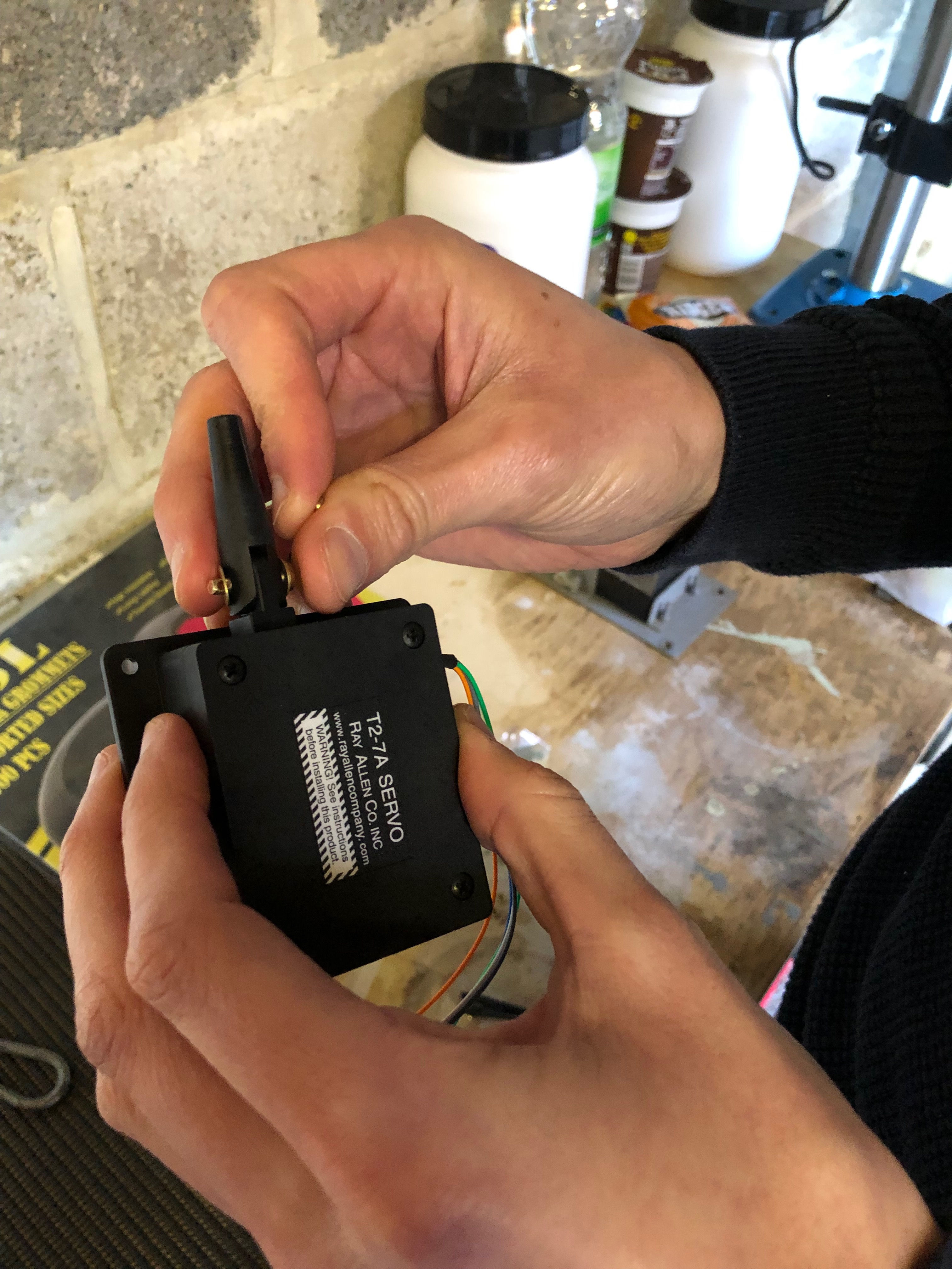
The first thing that needs to be done is to set the trim motor to its extremes so it can be set at midpoint.
The midpoint is 8.5mm which is set by connecting to a 12v battery to move it to that position.
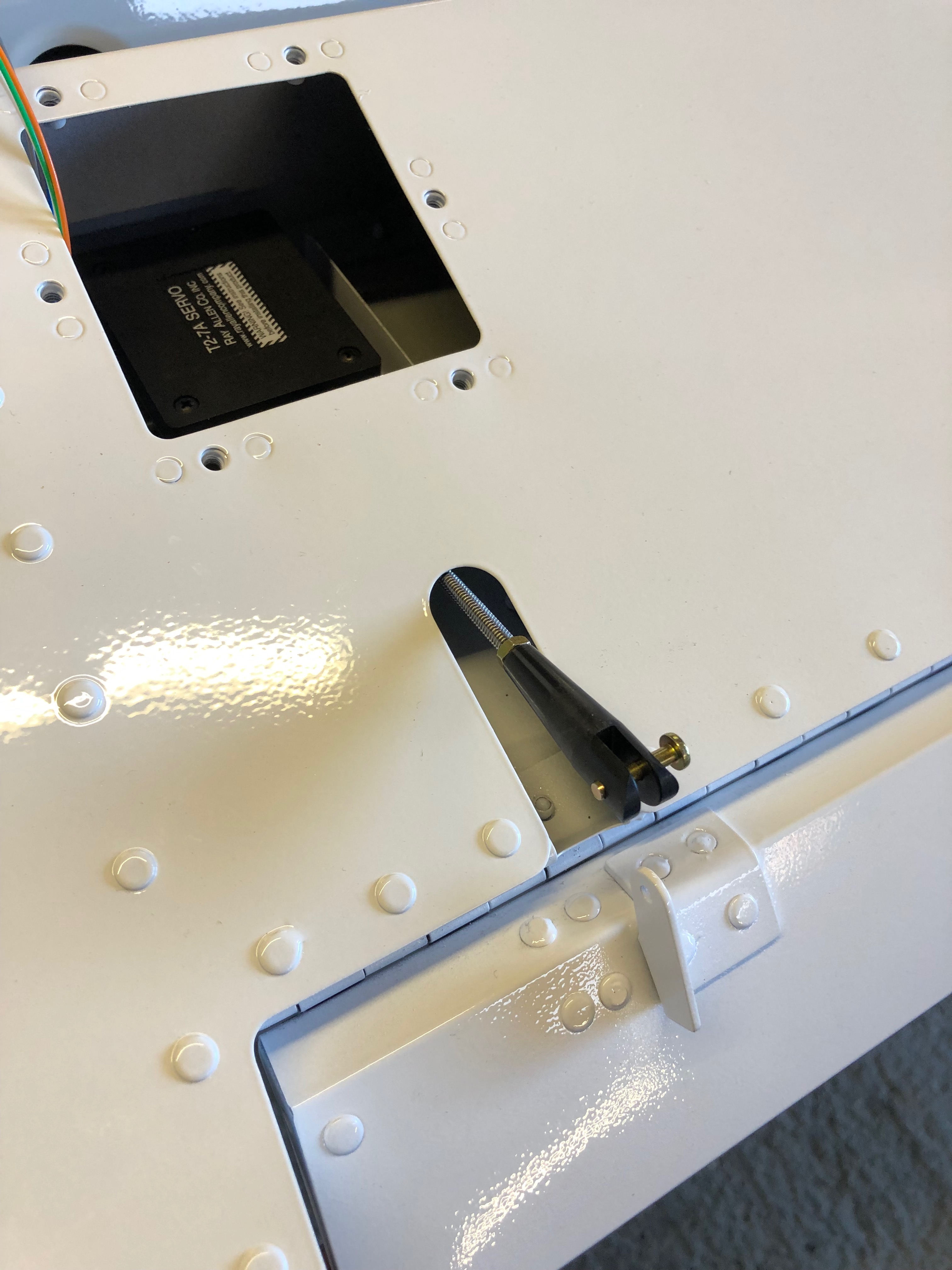
The servo is temporarily installed with Clecos, the other clevis is attached and adjusted so the trim tab is inline with the elevator.
The Clecos are removed and M3 screws, nylon washers and nylocs nuts are used to secure the servo.
Once correctly adjusted the pin and clevis is secured with a split pin.
Today focuses on finalising some of the work I had already started but was waiting on parts.
First up is to rivet the throttle into place.
A view of the throttle installation from the top.
Next is to replace the 5/16″ bolts that were found to be damaged.
Once tightened the nuts are marked with torque seal to indicate any movement in service.
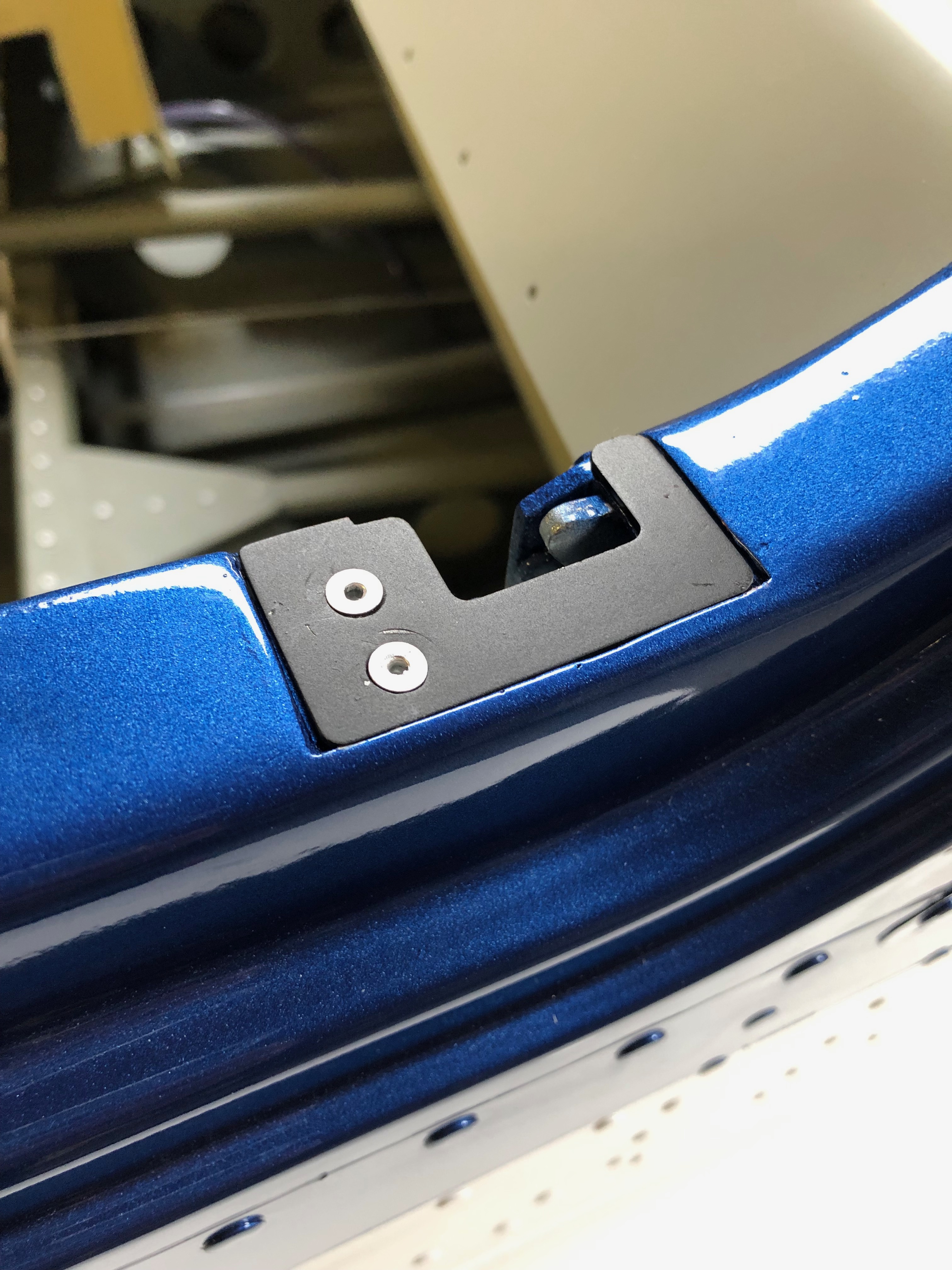
The canopy latch striker plates are riveted into place.
And the spring return plate is riveted into place and the spring connected.
The trim motors are normally riveted into place but I’ve decided to use an M3 bolt and nyloc bolt as it will be easier to change should there be a problem.
The wiring needs to be done next but I’ll leave that for another day.
Chris came down today to visit, see the plane and help me do some of the jobs that require two people.
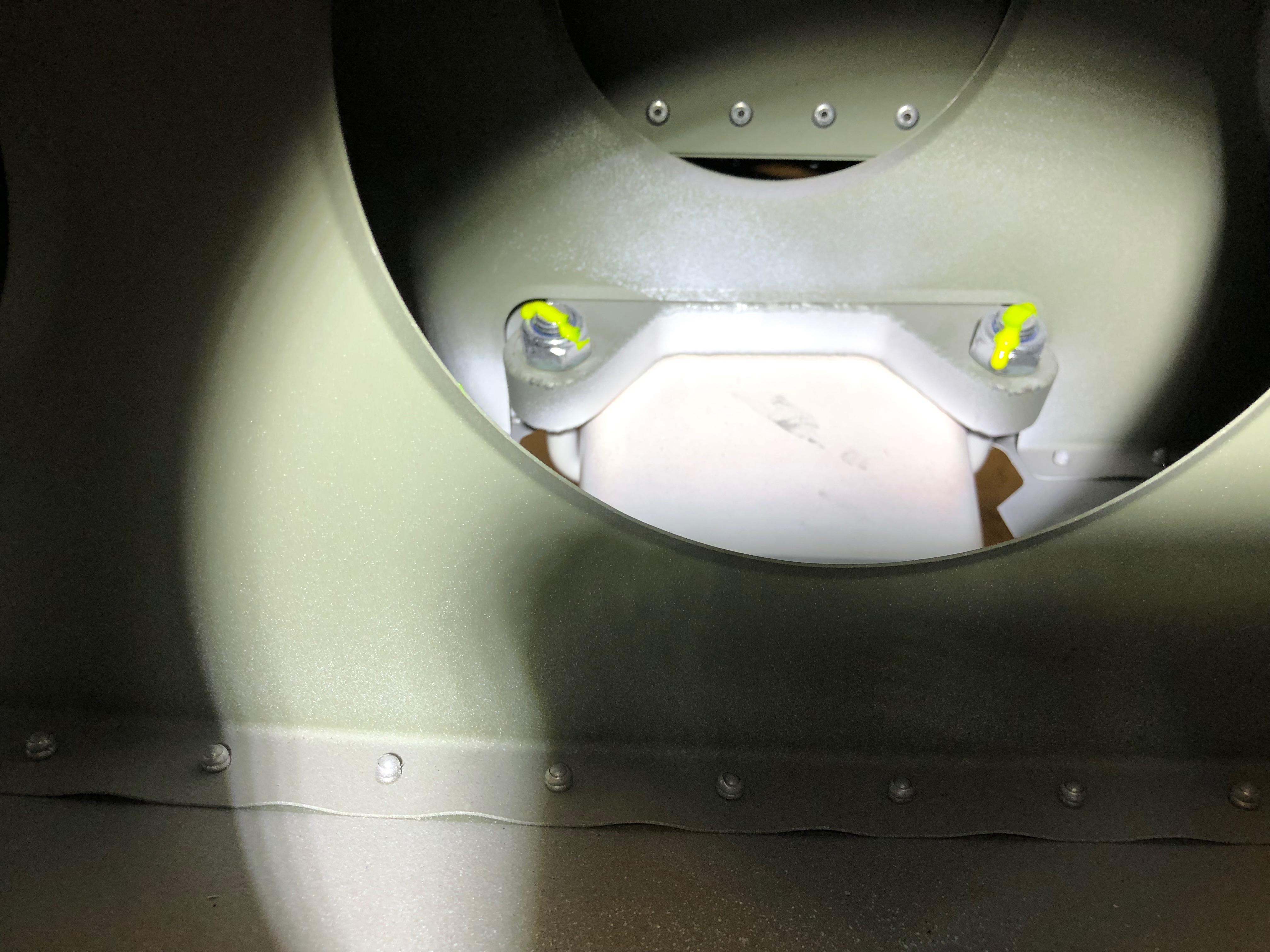
First job today was to check the undercarriage bolts for tightness. Unfortunately two of the four bolts did not tighten so were removed for inspection and were found to have damaged threads. These will need to be replaced.
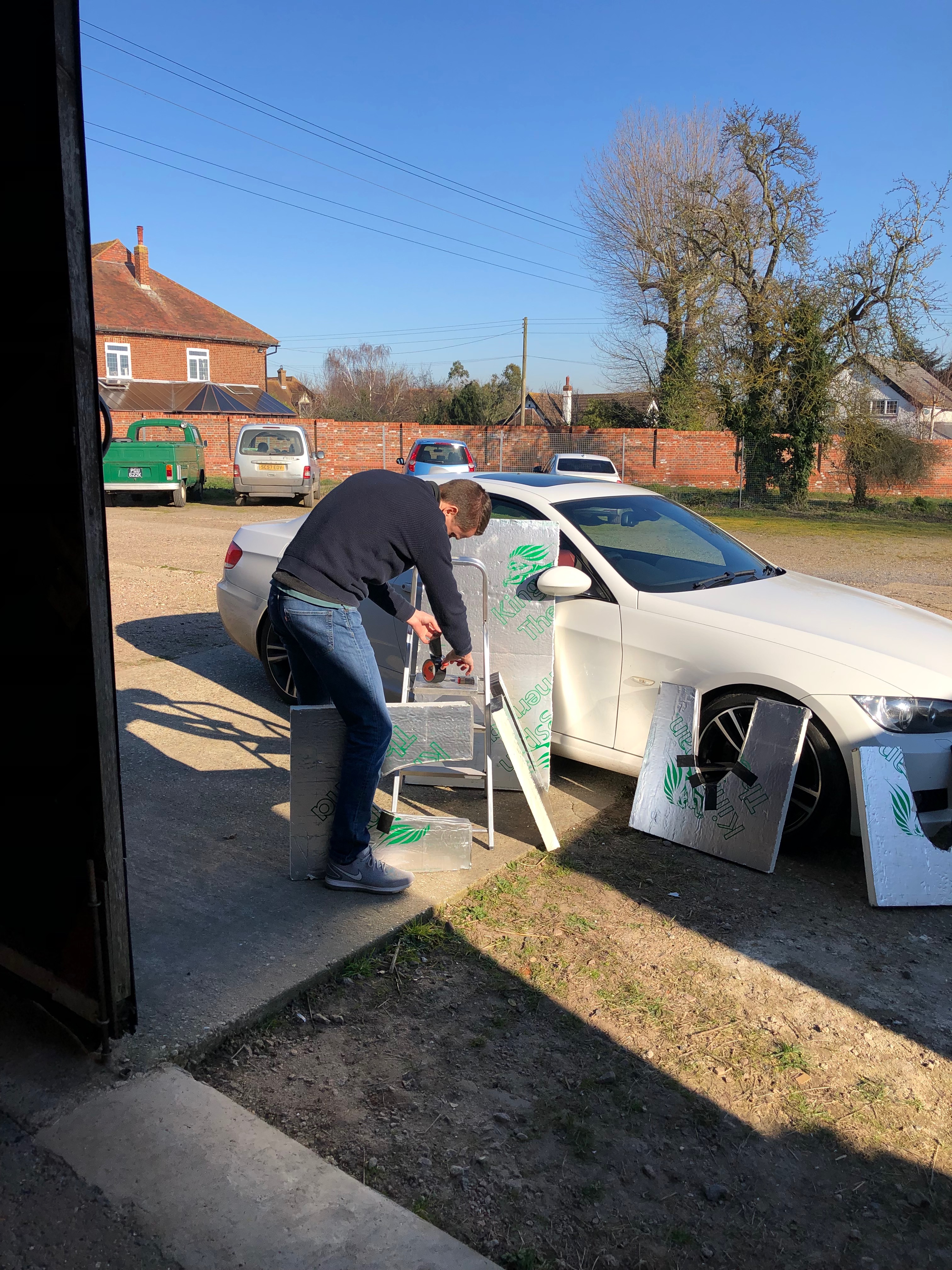
Chris making some wing stands .
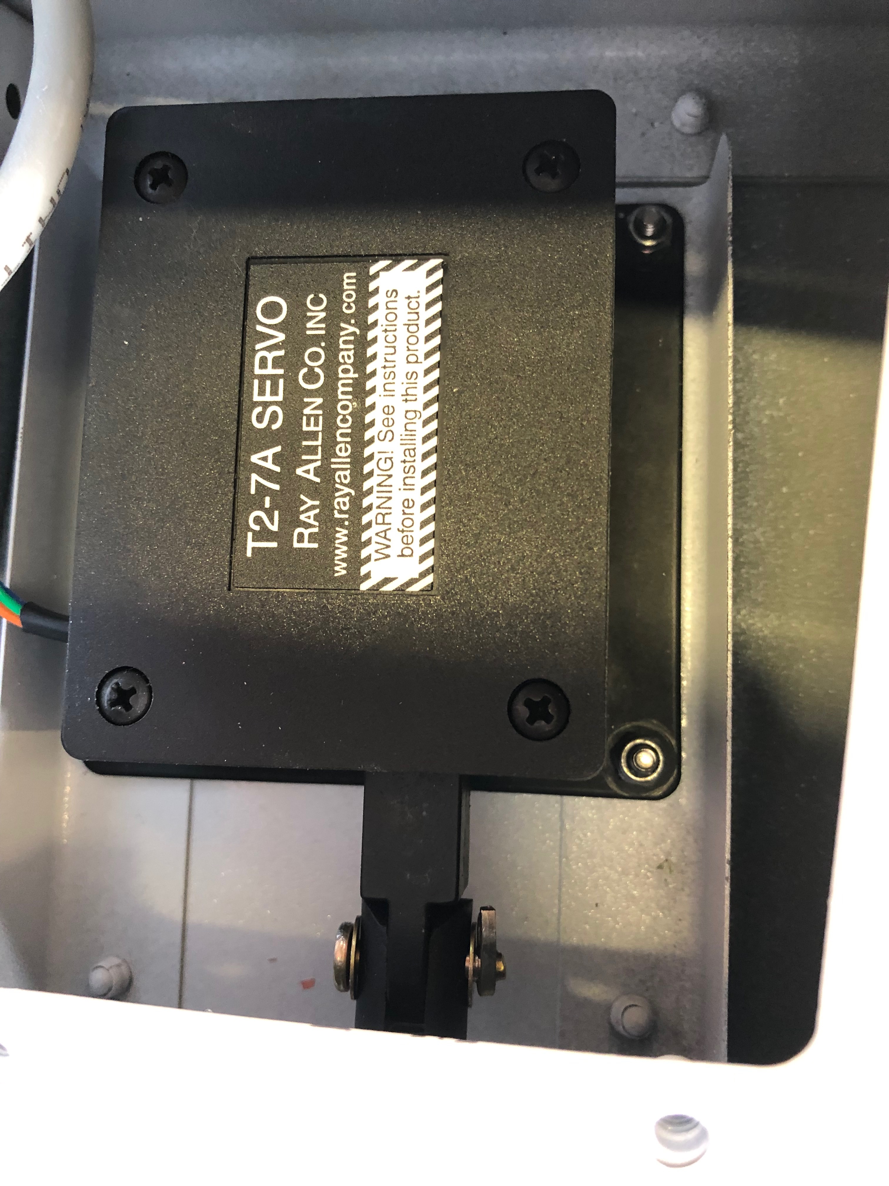
Our next job was to install the Aileron and Elevator trim servos.
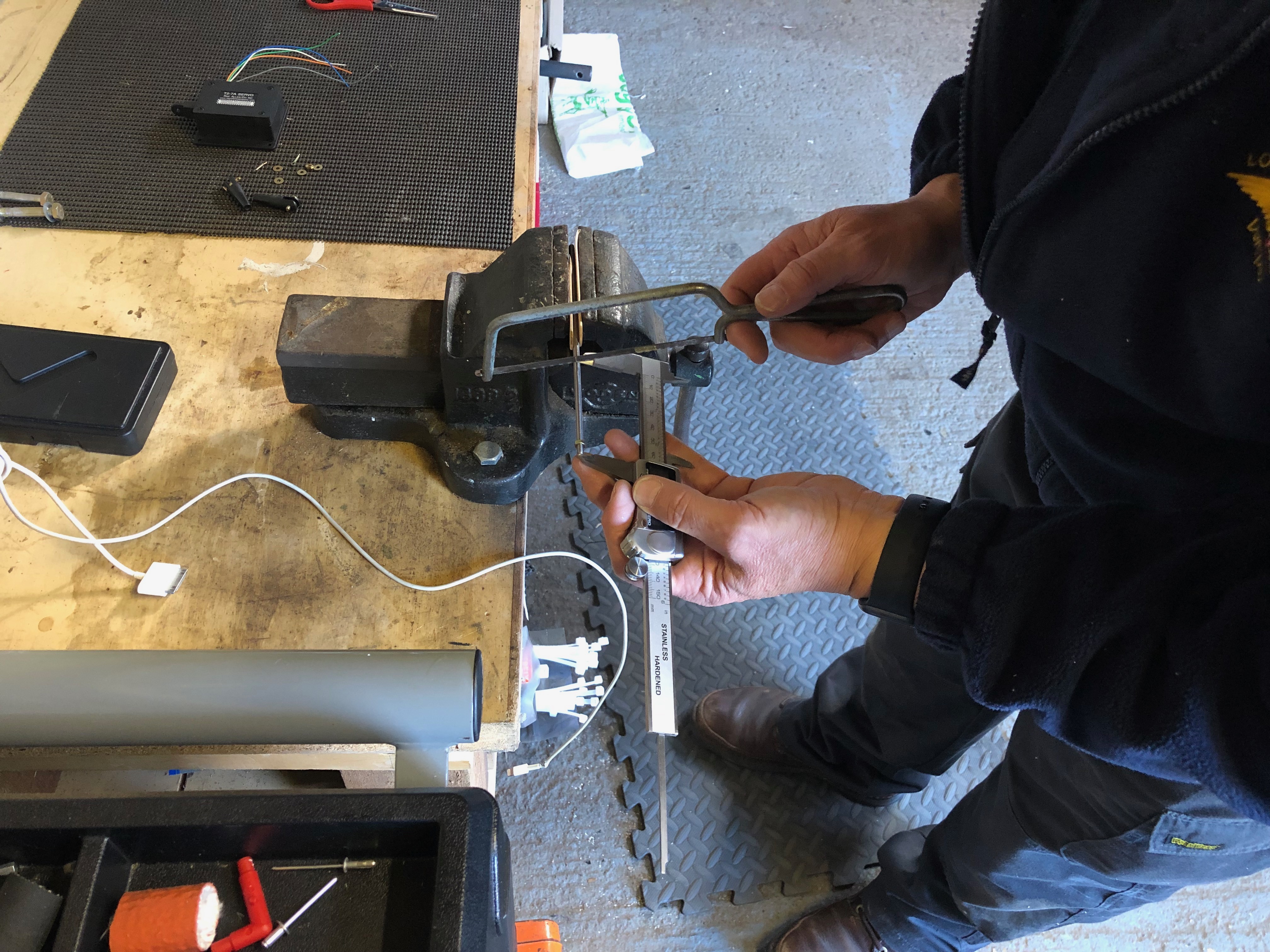
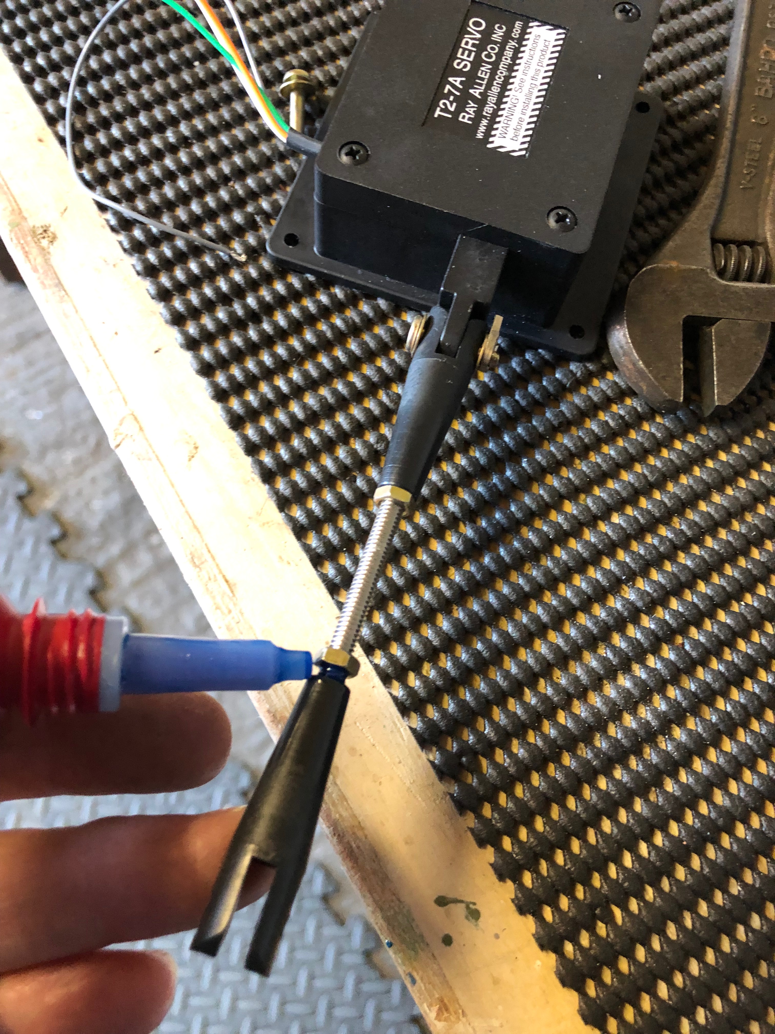
First job is to cut two threaded rods one 85mm for the elevator and one 65mm for the aileron.
The clevis is added and secured with a split pin.
The servos need to be moved to mid position which can be done with the aid of a 12 volt battery. The white and grey leads can be connected to the battery in either polarity to move the servo in or out.
The servo is positioned in the recess and cleco’d in place so the control rods can be adjusted correctly.
Once adjustments are done the locking nuts are secured using Loctite 243.
The final installation.
Following the build of my Bristell NG5 Kit No. 382 Registration G-MLSY