A number of jobs planned for today. Complete the engine NACA ducting, install the clevis pins to the carb heat control and cabin heater, install the fuel pressure sensor, install the engine intake air box, install the MAP sensor pipe, adjust and set the cowl quick release fasteners and install the control stick torque supports.
The fuel sensor and adapter were left to set with Loctite 577 overnight so can now be fitted to the fuel hose that I had added for it.
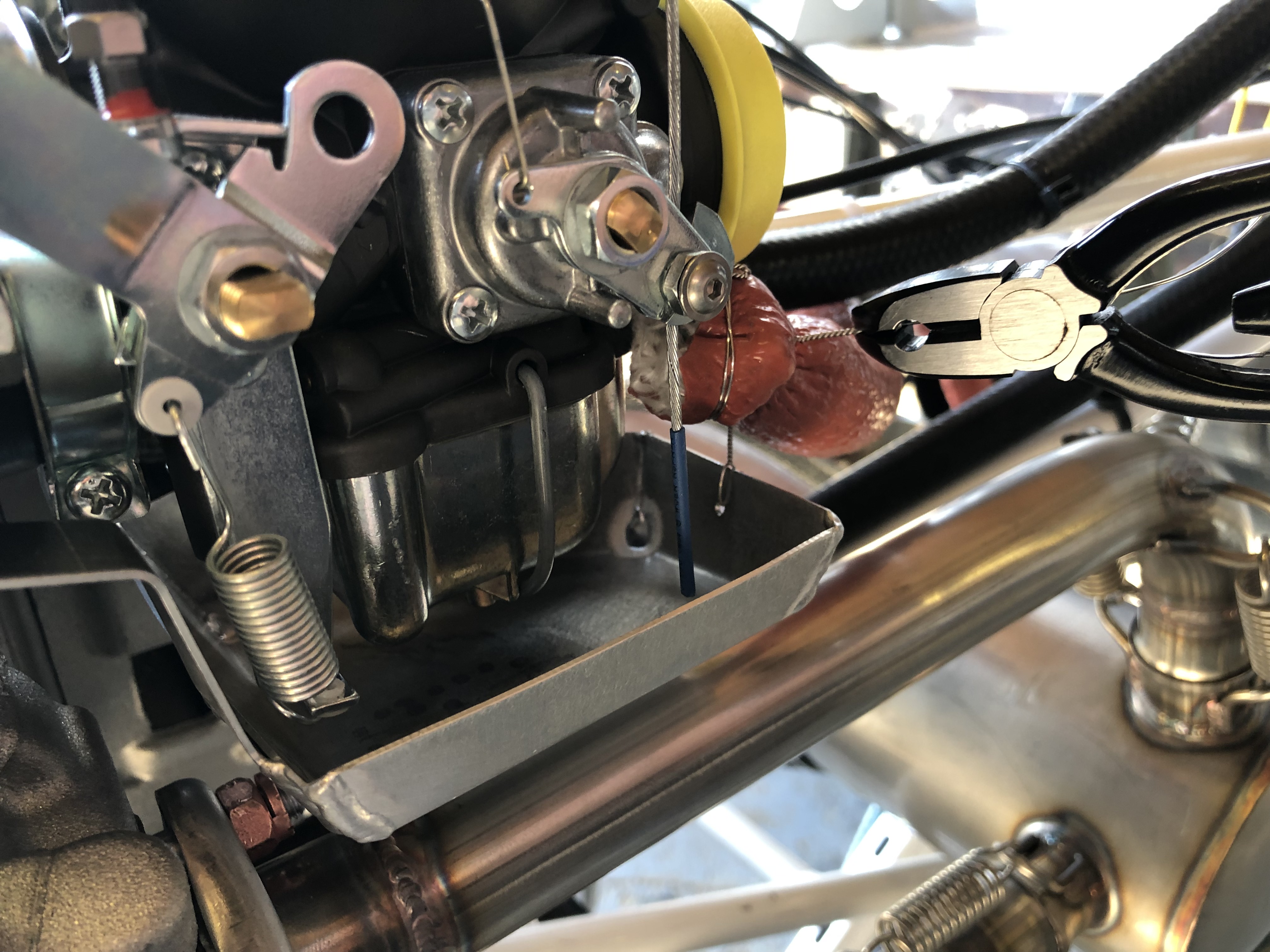
The hose is secured with a hose clamp and fire sleeve is added which is secured in place with locking wire.
The sensor is secured against movement and vibration with a stand-off.
These are the clevis fittings that are used on the carb heat, cabin heater, screen de-mist and park brake.
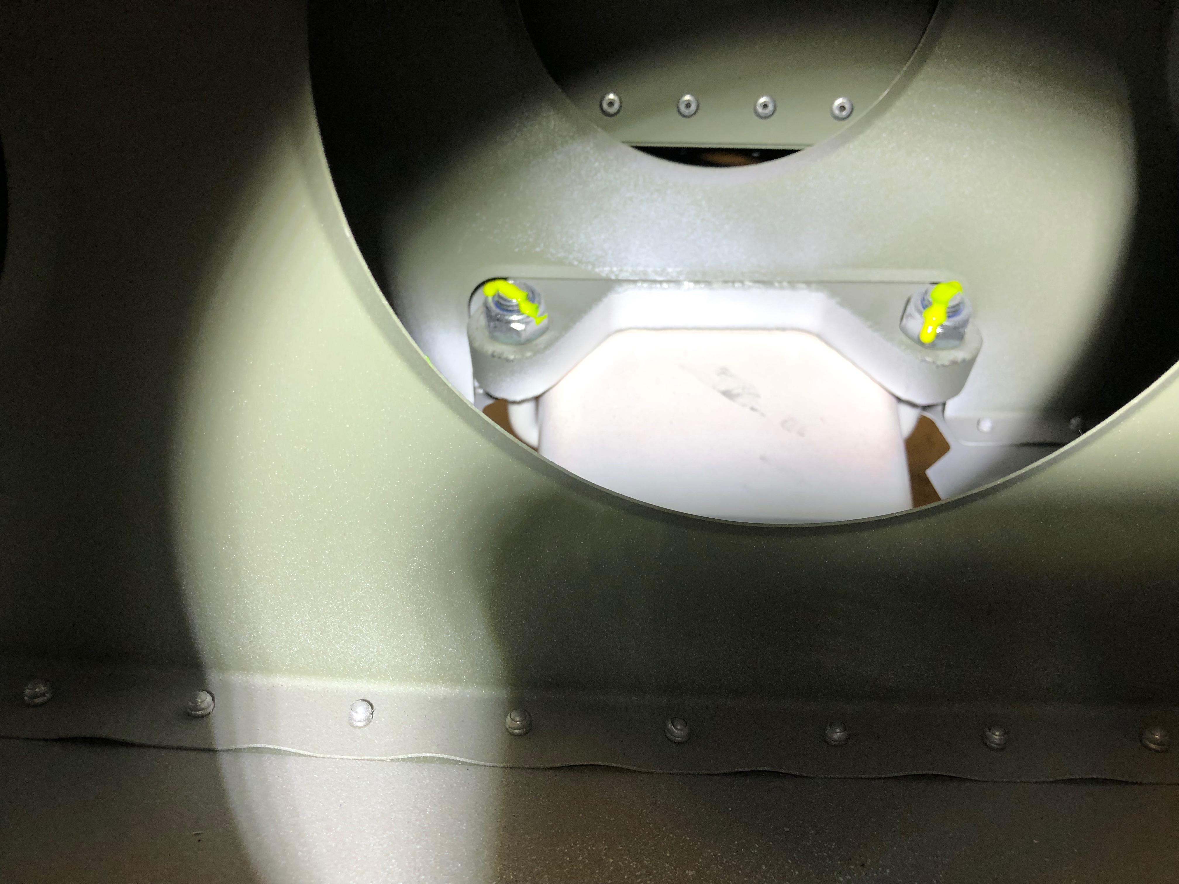
Now the sealant is set, the air box is mounted on a couple of brackets off the engine mount. It’s secured with a couple of Nyloc nuts underneath. Two short pieces of sturdy rubber hose are fitted over the carburettor inlets and the air box and provide a flexible joint between them.
They are secured in place with jubilee clips.
The SCAT ducting is secured in place with jubilee clips to the air box intake and the starboard lower cowl side NACA duct.
The ducting to the port NACA duct is run to the rear of the exhaust and then into the centre inlet on the heat exchanger, secured with jubilee clips and held in position with a couple of tie wraps.
Port NACA duct.
Even with all the space that the Bristell has It can get a bit tight with all the hoses that are required.
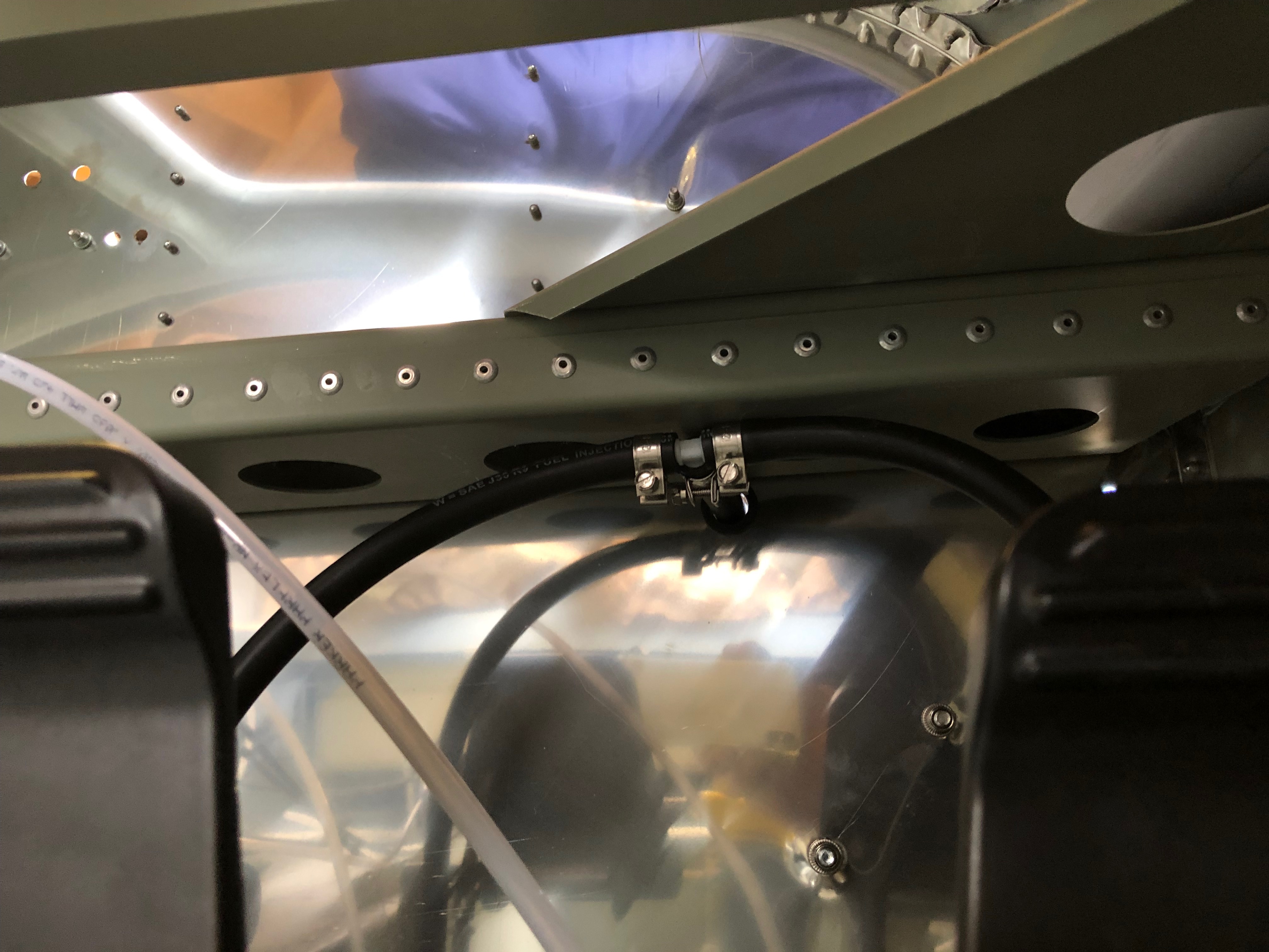
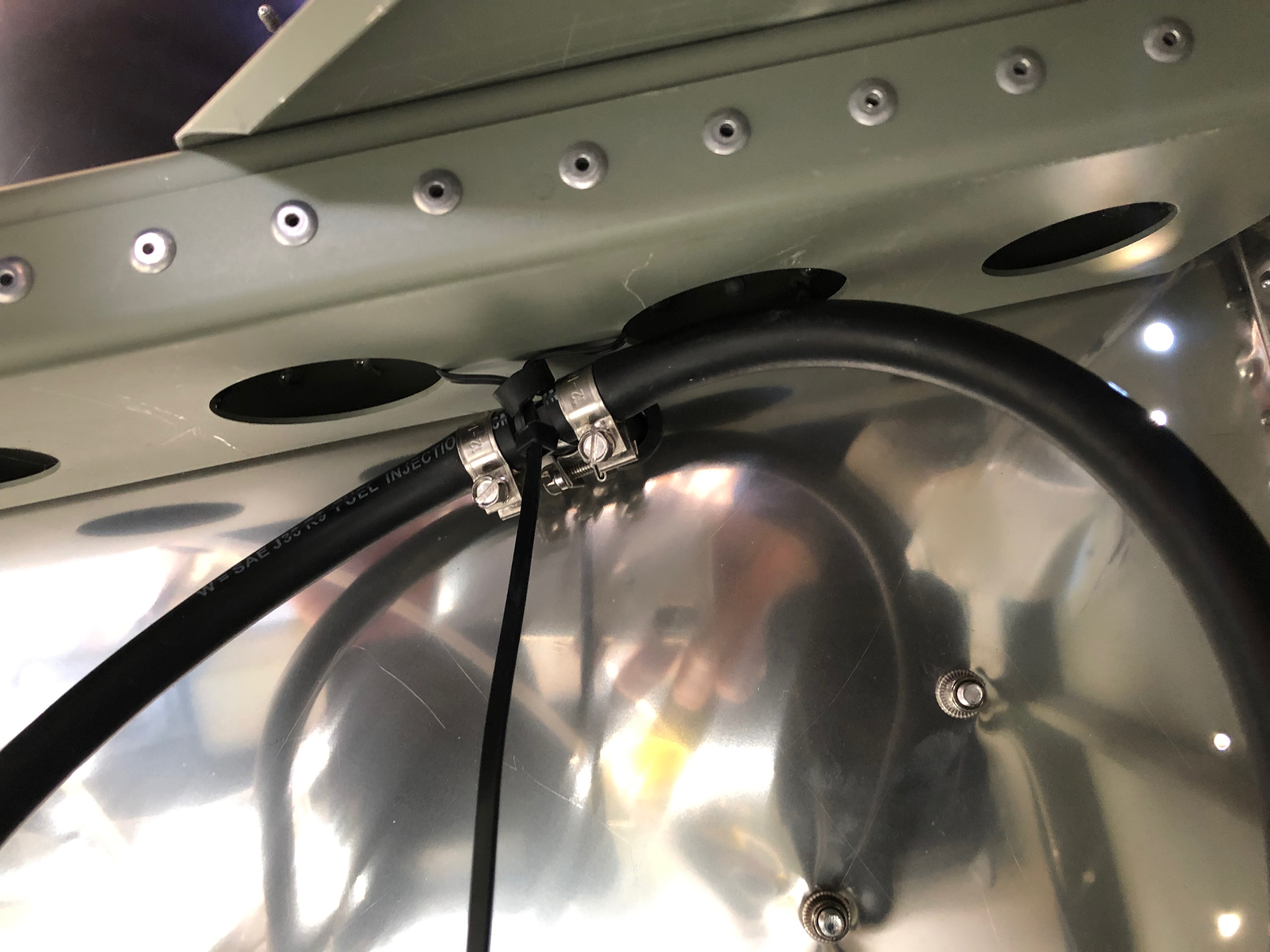
The MAP sensor has already been mounted so just needs a pipe to be run and of course some wiring at a later stage…
I’ve used 5.6mm ID R9 fuel hose between the carburettor balance pipe and the MAP sensor.
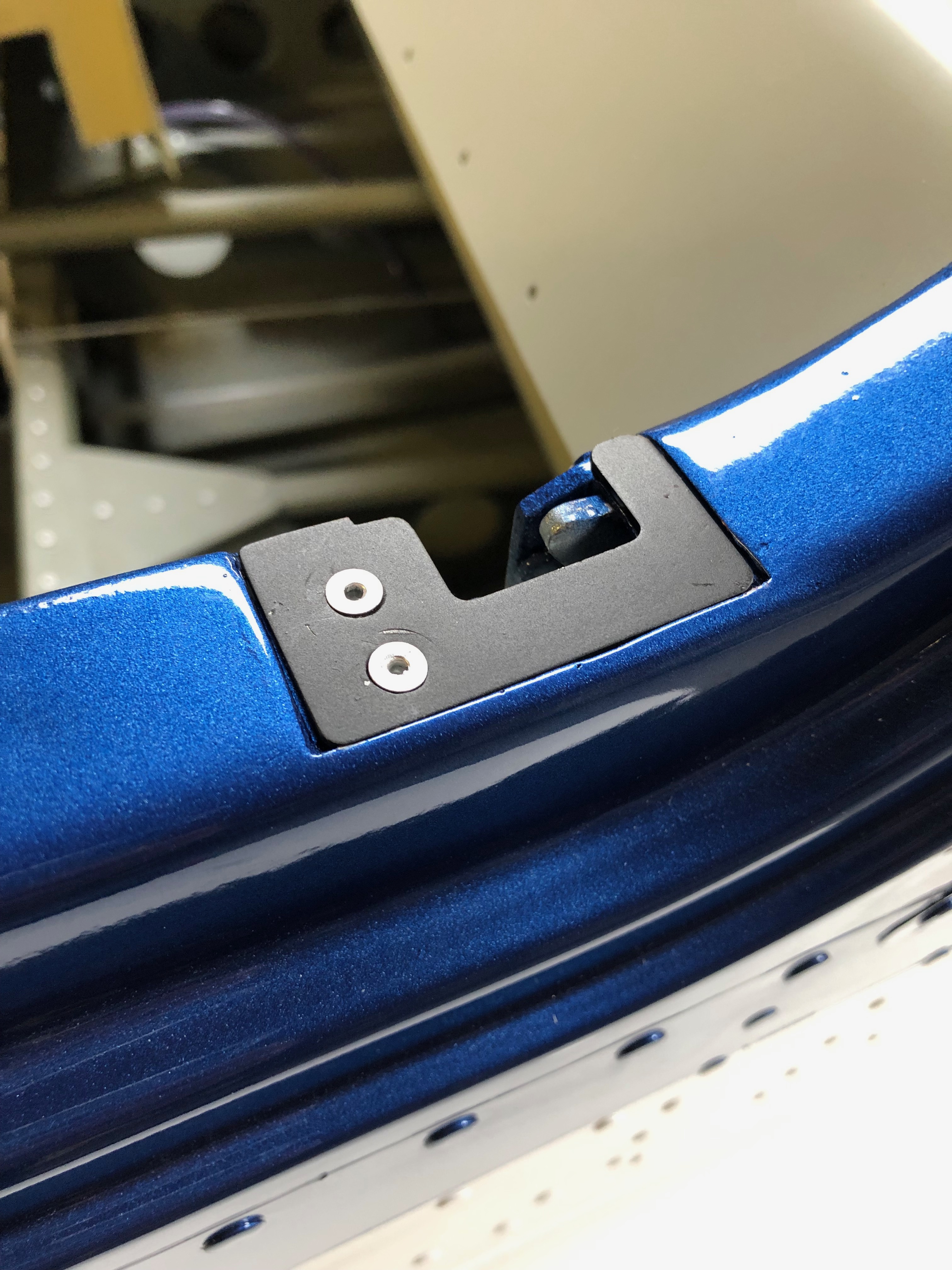
The quick release fittings on the fuselage have been riveted in place and now require them to be adjusted and set. First thing is to screw them in…
until they are flush with the cowl.
Once adjusted the pin can be pulled that sets them into position.
They are released by a quarter turn of the Philips screw and the fitting stays set in place.
I still need to repeat the process for the top cowl and the oil inspection cover. Ian will be installing the fittings during next week. Unfortunately the rivets need to be ‘squeezed’ and I don’t have the tool to do it.
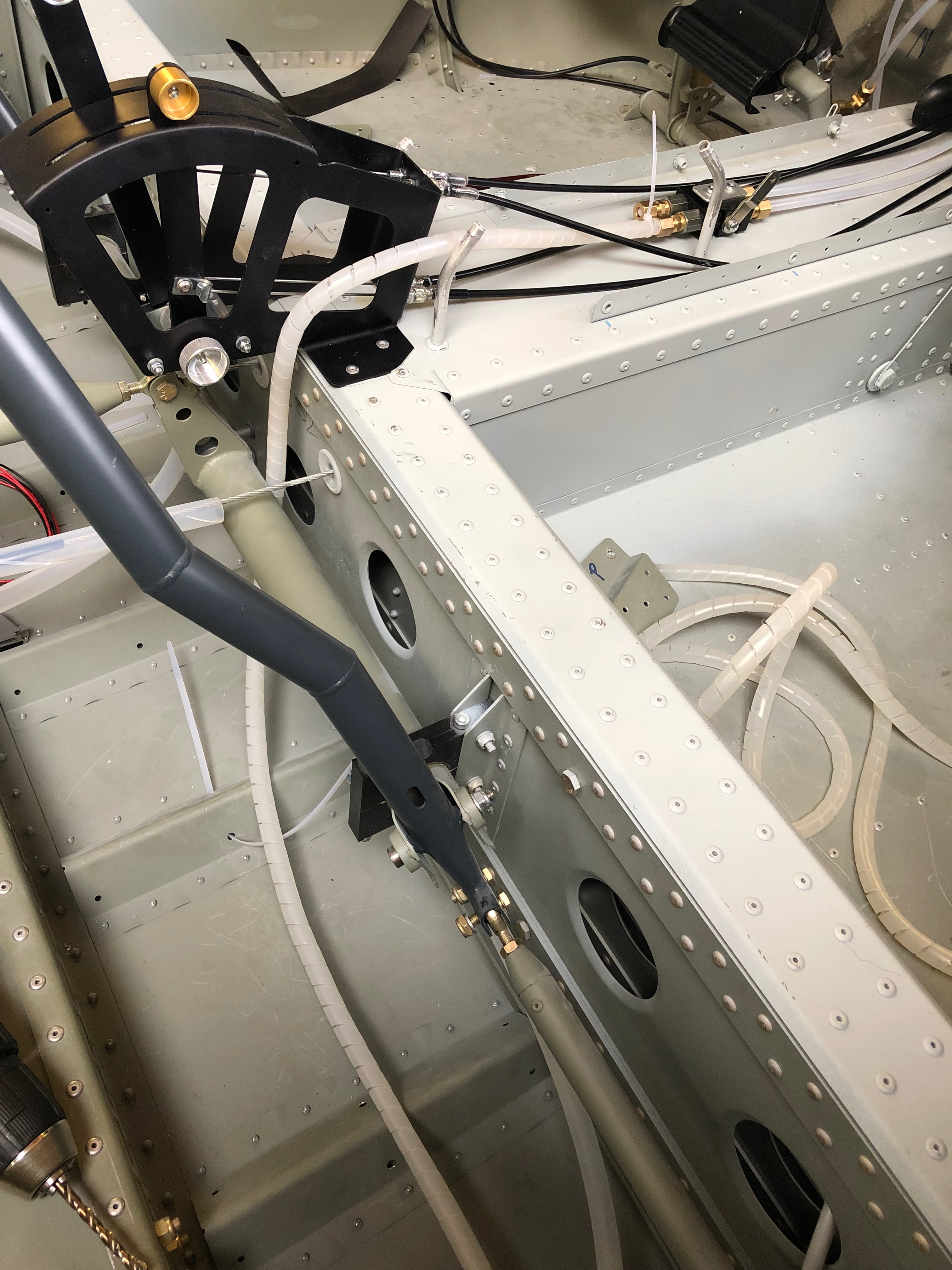
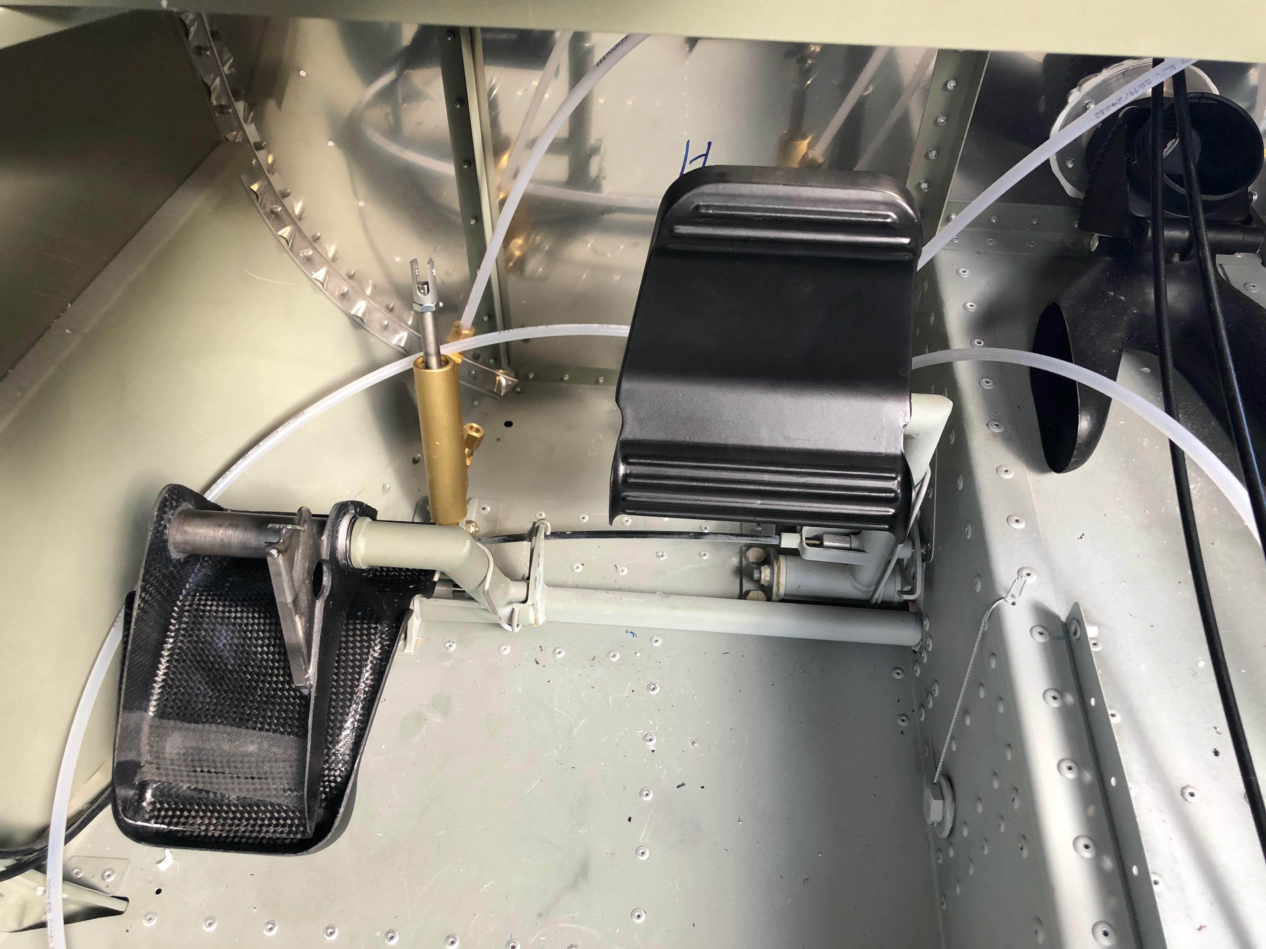
Now I’ve picked up the control stick torque arms I can start work on the control sticks.
The fittings need to be checked and secured although they will need to be adjusted when the wings are fitted to centralise them, set the limit screws and check aileron deflection are correct.
The torque arm is attached at one end using the bolt from the control stick bearing.
The other end is secured with a 4 x 15mm rivet.
Both torque support arms fitted, completing a fairly productive day.
I’m still not 100% sure on the layout of the screens and associated control panels so I thought it would be good to add the pilot seat so I could check different layouts.
Once the seats were installed I could sit in the aircraft as I would normally fly it. The panel here has most of the bits I need but is missing the flap switch, some warning lights and the air vents.
I’ve stuck the pictures on using glue dots that allow me to move the pictures about. I can then do a ‘touch’ test on the layout to see what works best.
A few smaller jobs, including exhaust wrapping, sensor fitting and cable oiling ahead of fitting the water thermostat that I finally received today.
The landing lights come with a couple of spade connectors that need to be crimped on…
and then slipped into the connector block. I’ll need to do the same thing when I come to install the LEDs into the wing.
The MAP sensor is fitted to the firewall in a suitable position making sure that the plug don’t foul one another.
The space between the water bottle and regulator seems to work well.
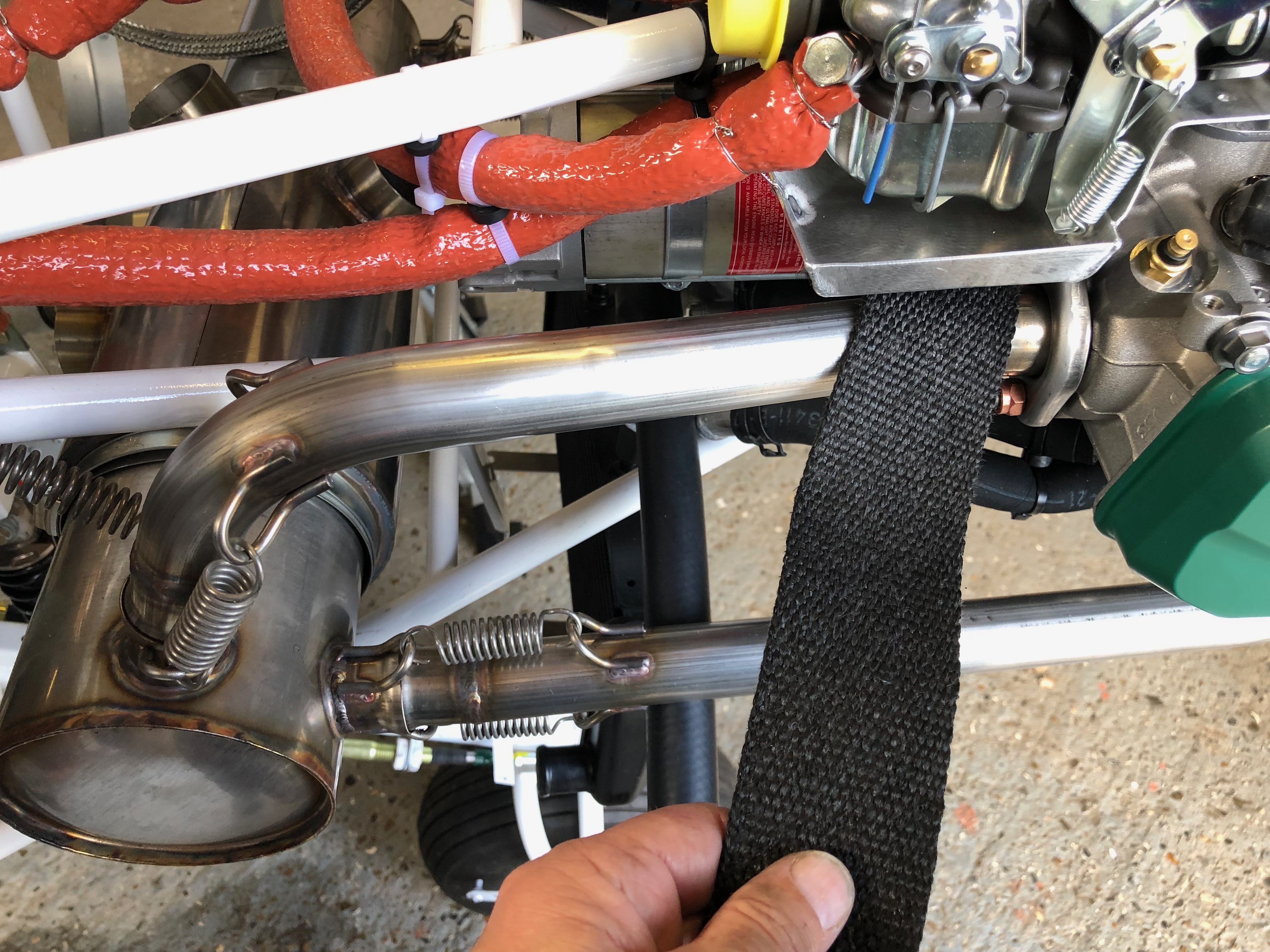
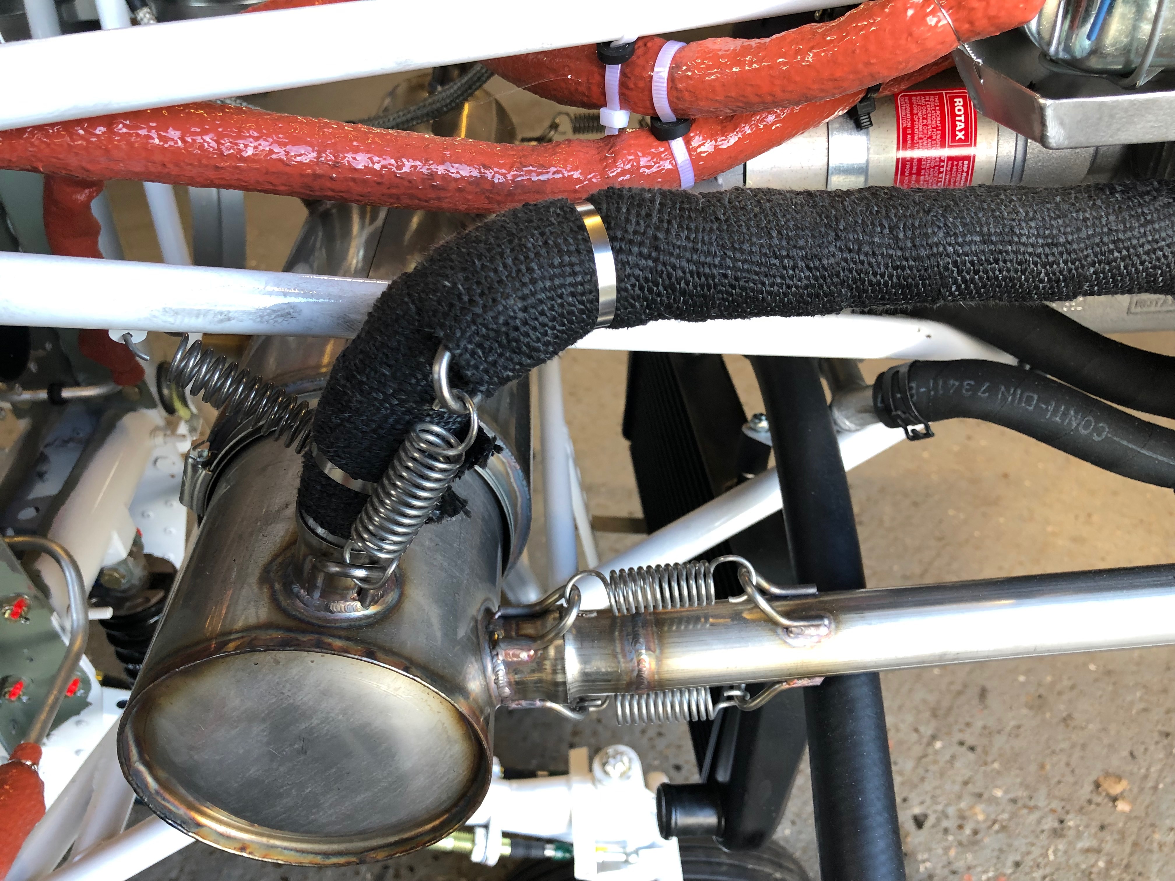
The front exhaust pipes covered in exhaust wrap and secured in place with stainless steel ties.
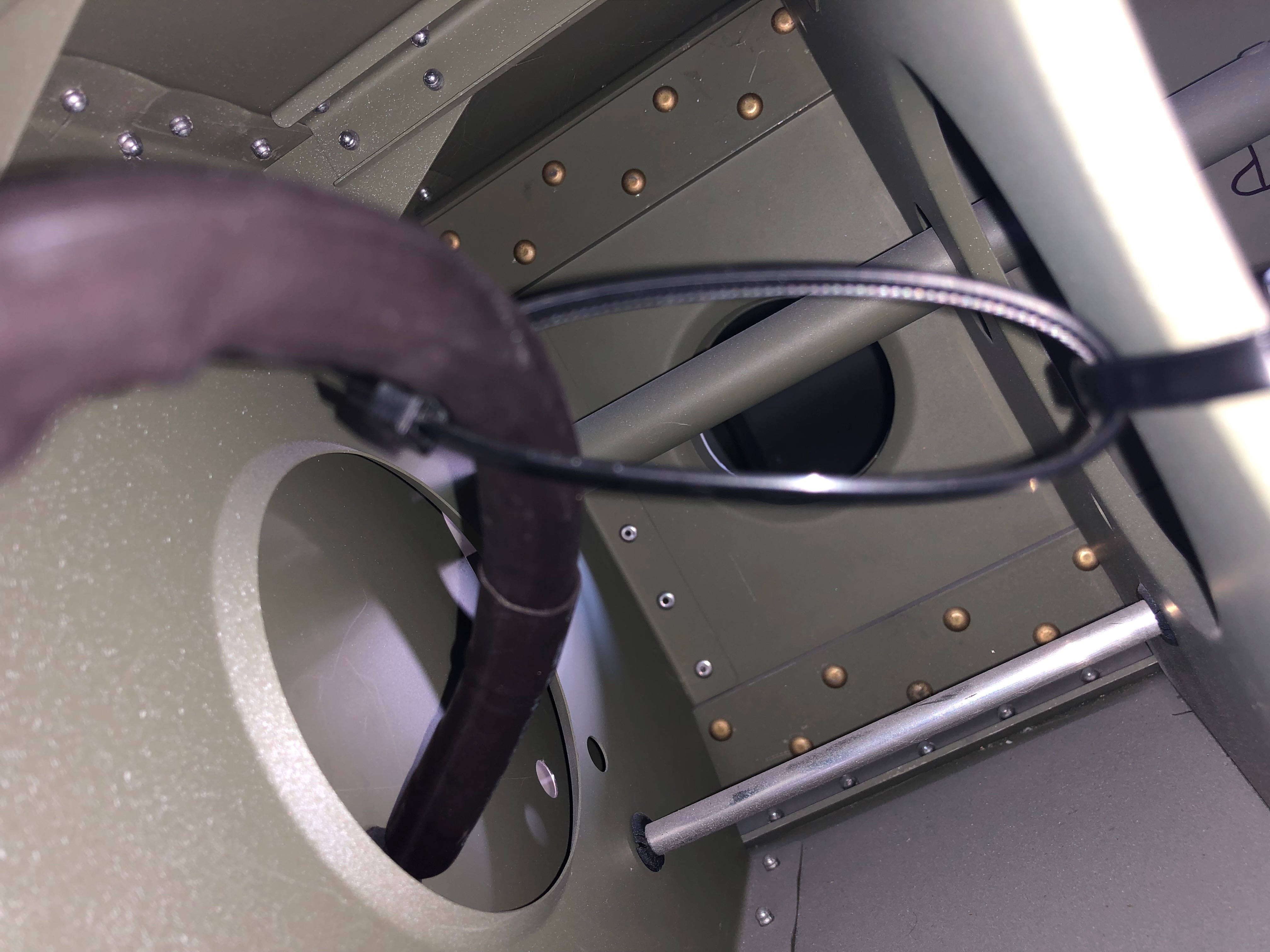
There’s several cables that need to be installed later in the build. Unlike the throttle cables these aren’t lined so require some lubrication.
Received at last! Good ol’ Parcel Force have had this since the 5th March but never left a card. It’s lucky I asked for an update on delivery from Silent Hektik otherwise I’d still be waiting. This is the 3rd time Parcel Force have completely screwed up on a delivery to me – I will never use them again!
Today was dedicated to completing the brake installation and starting on the exhaust wrap.
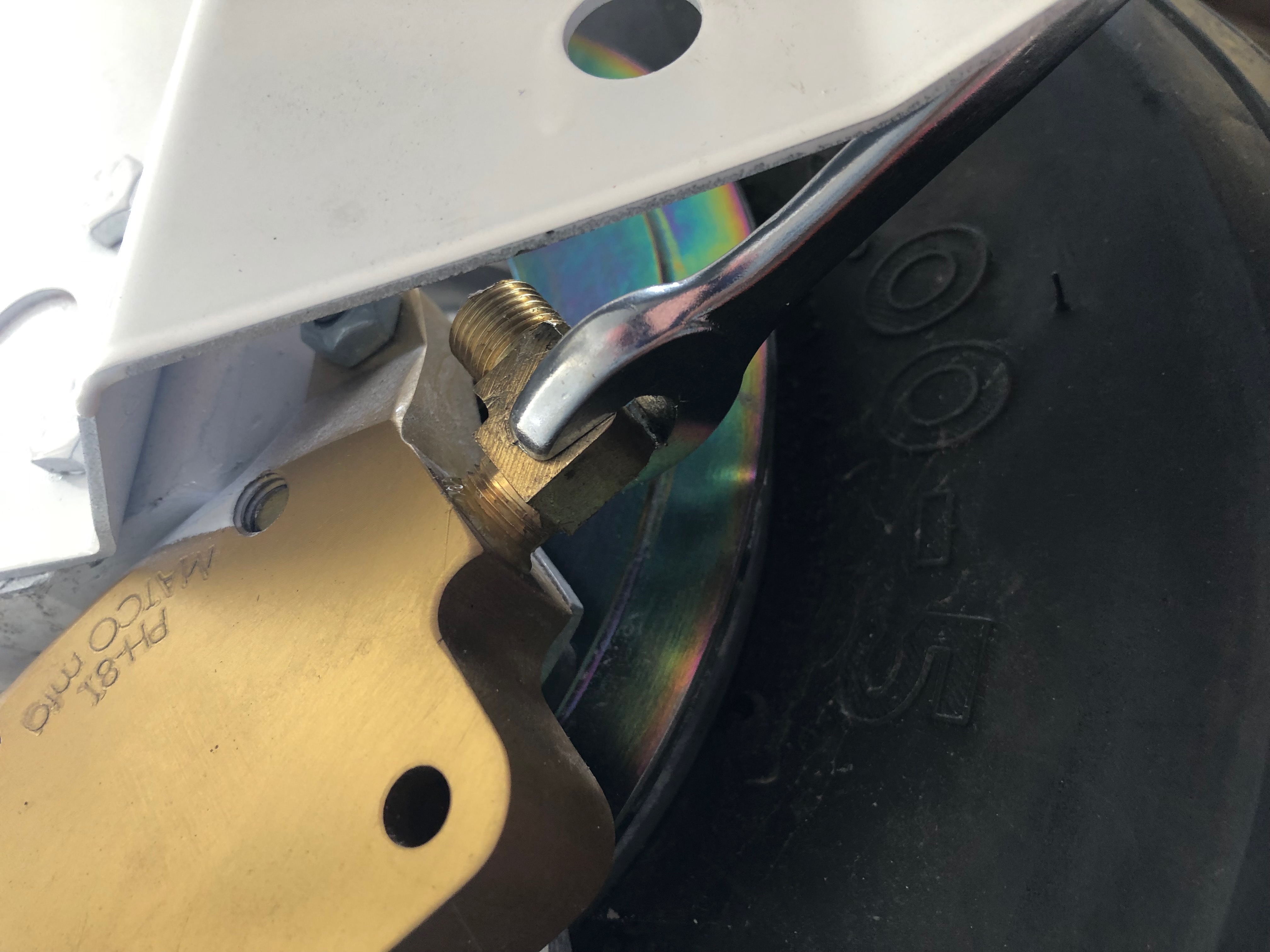
First up is to add Loctite 577 to the last two hydraulic elbows and fit them to the brake callipers.
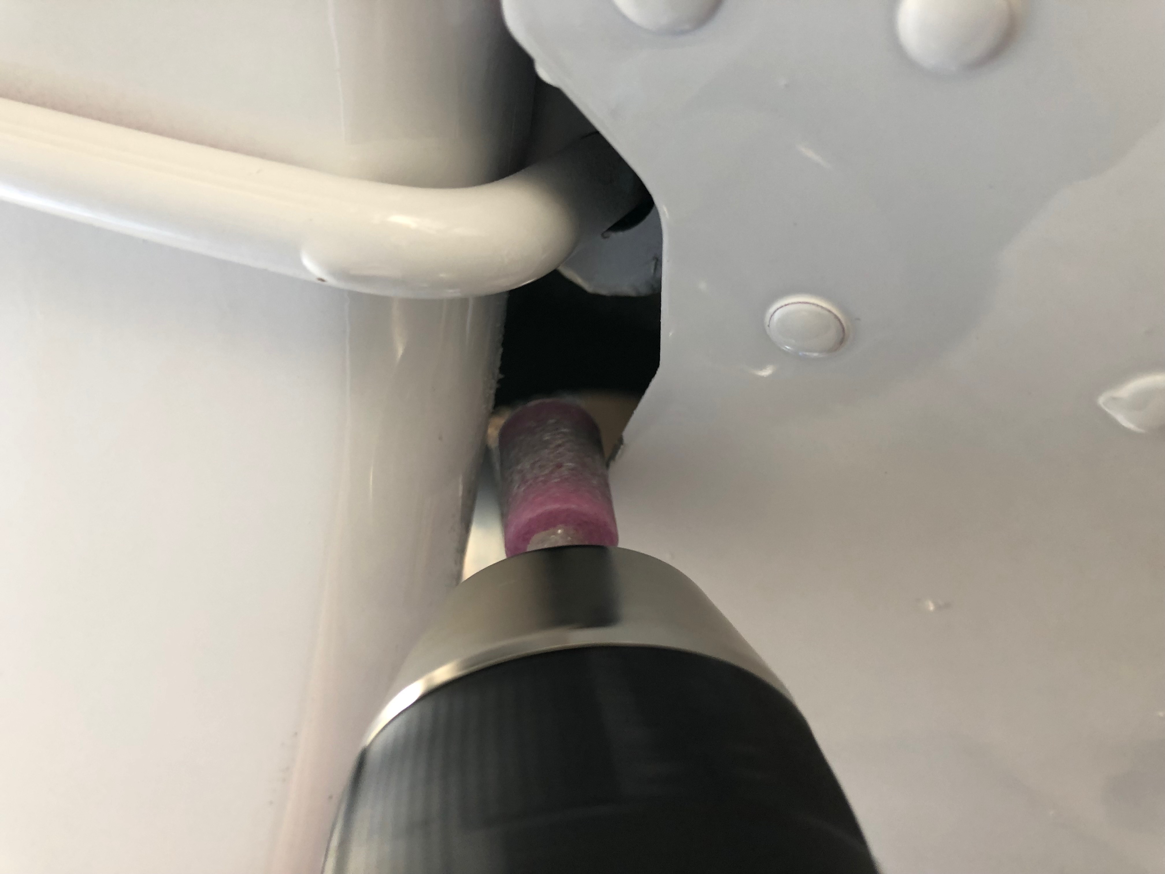
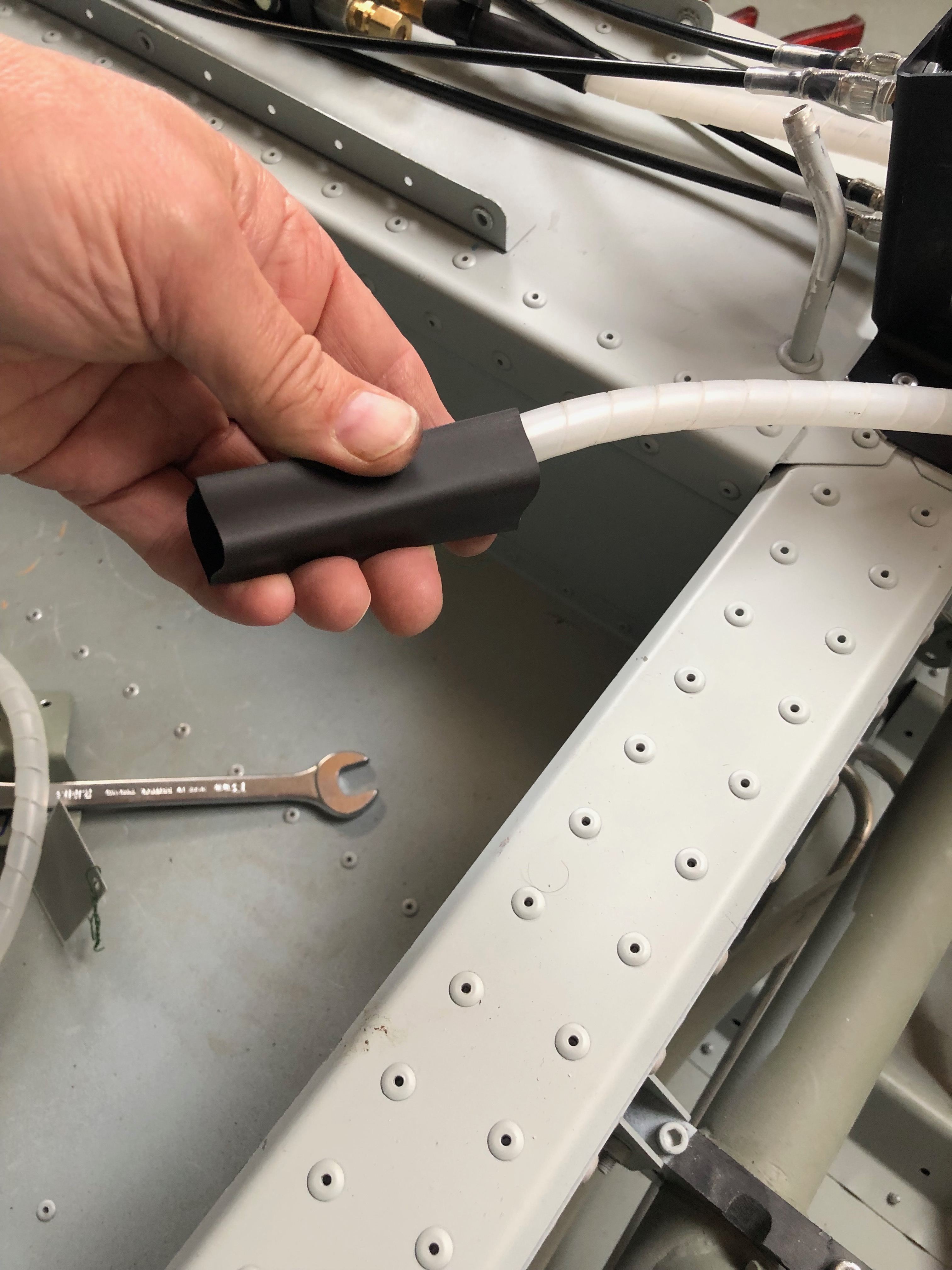
I thought it would be a good idea to cover the spiral wrap with some heat shrink tubing to protect the hydraulic pipes as it emerges from the fuselage and runs down the first part of the landing gear leg.
A slight change to the opening needed to be made to accommodate the extra width of the covered pipe.
The cover is slid over the pipe and secured in place with a tie wrap.
The pipe will be subject to movement when taking off and landing so the pipe is cut long to provide a loop to accommodate the movement.
The pipe run from the the master cylinder fitting to the park brake unit looked to be under stress so I removed it, cleaned it up and refitted using a different angle which allowed the pipe to ‘flow’ better.
Before tightening the compression fittings a metal anti-crush ferrule is inserted.
The pipe run runs over a ‘sharp’ edge so I added some protection to avoid chaffing.
The pipe is held lightly in place with some cable ties.
Took much longer than I expected but the brake system is complete – at last!
To protect the adjacent pipes from the heat of the exhaust I decided to cover the downpipes with exhaust wrap.
The starboard rear downpipes completed.
Run out of time but will take the landing lights home and fit the spade connectors as it’s a small job that can be done at home.
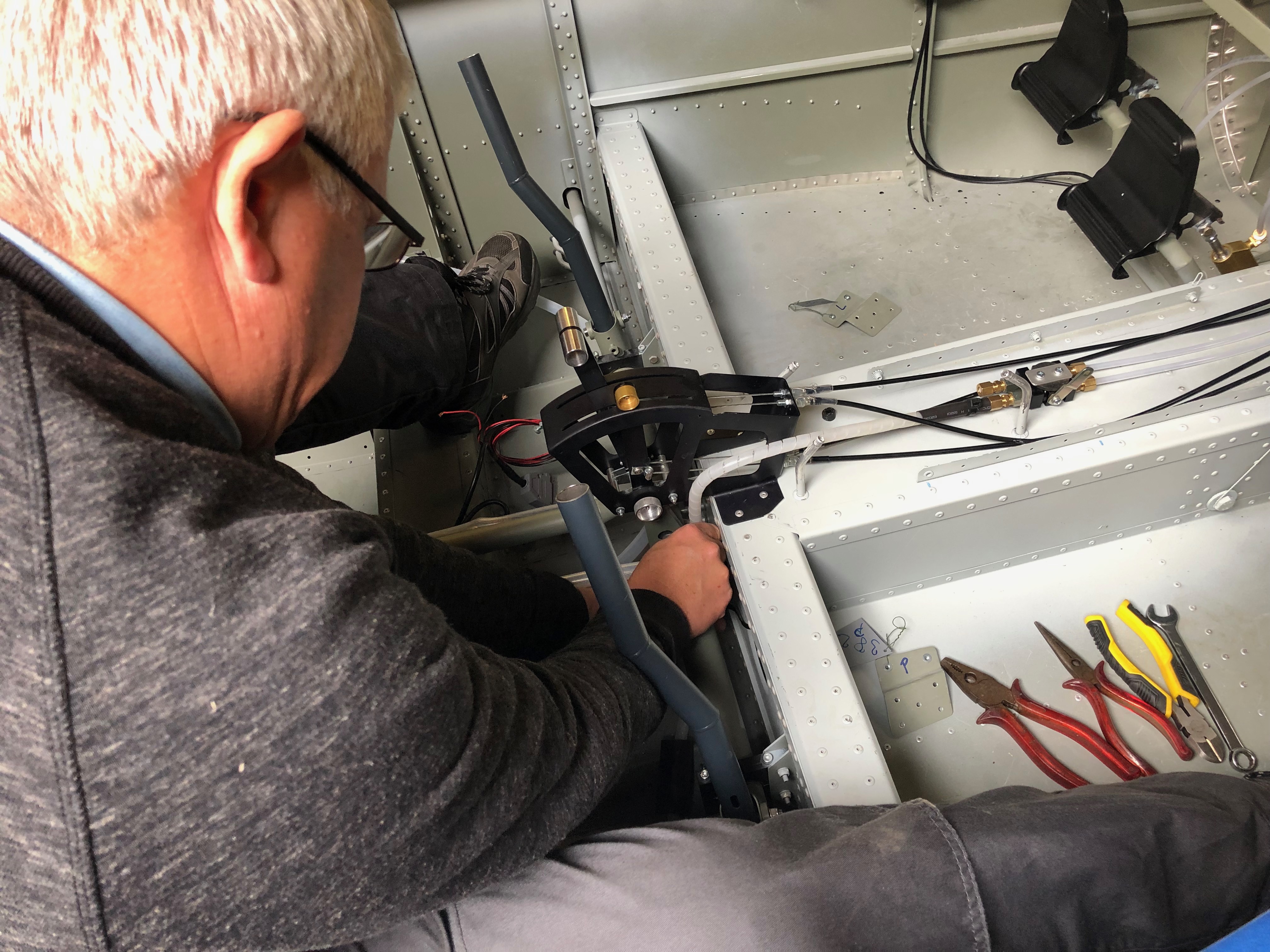
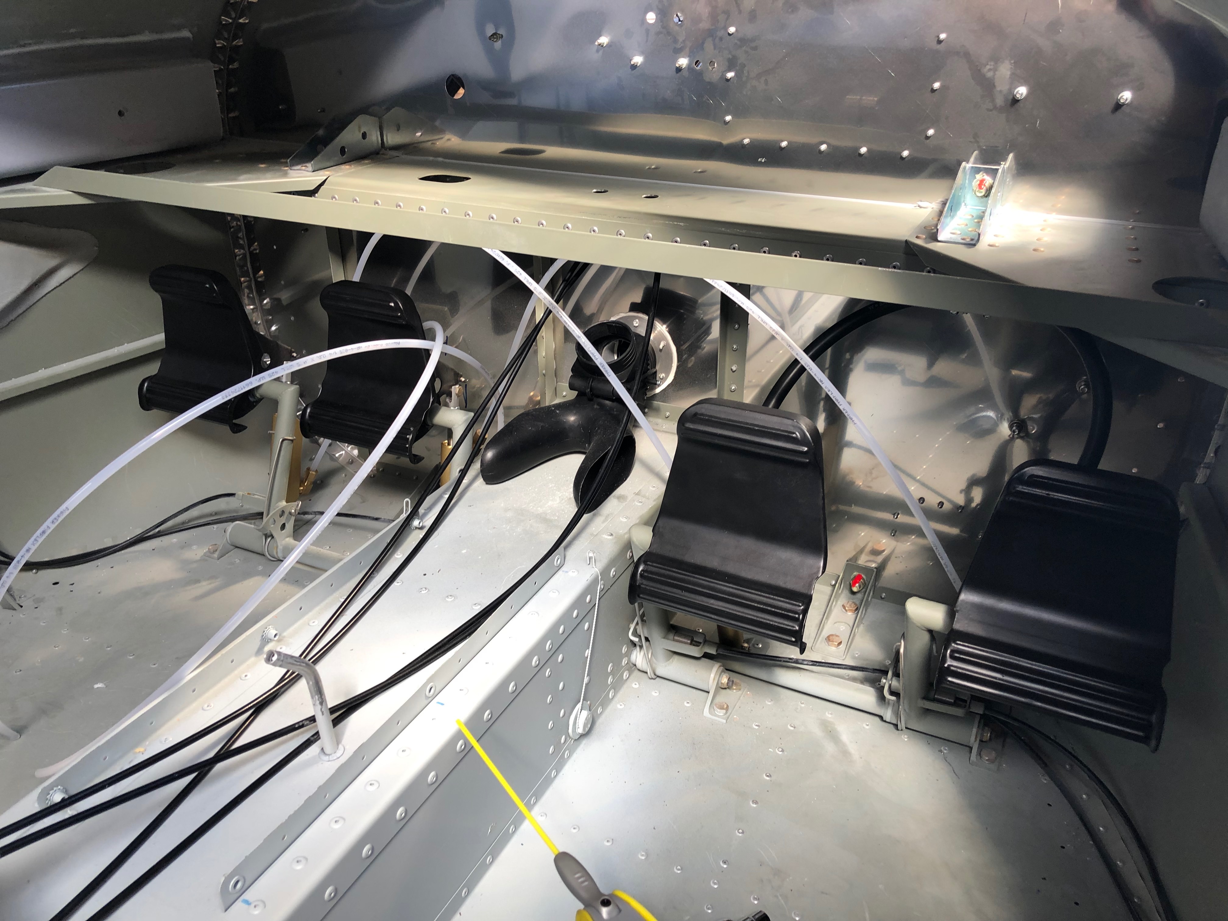
Karen came to help me complete the brake pipe install inside the cabin as it’s fiddly and needs a second pair of hands. certainly saved me some time.
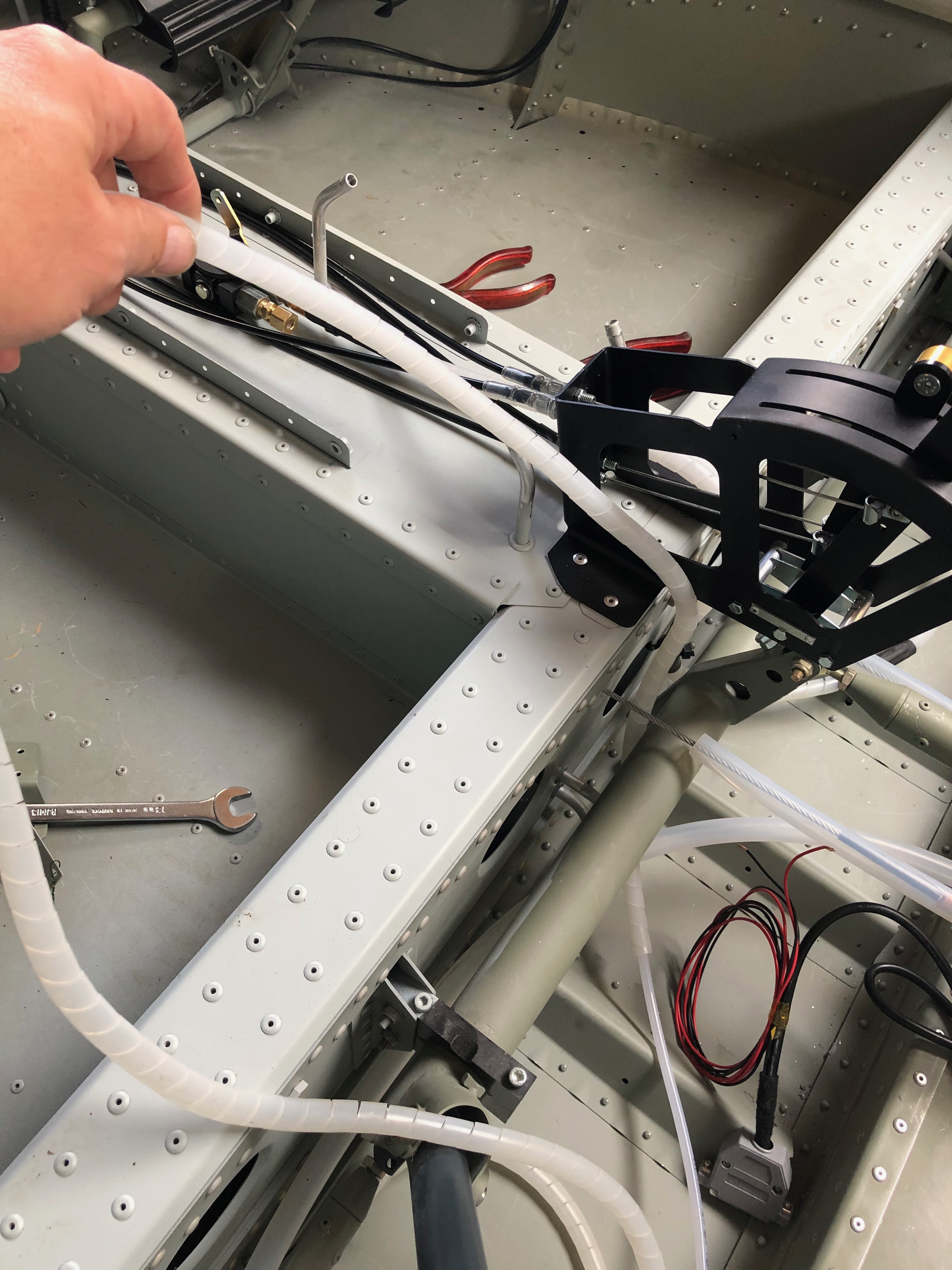
After running the hydraulic pipe to the side of the fuselage it’s covered with a protective sleeve to prevent the pipe from chaffing. I’ve chosen to use a spiral wrap similar to that used as a cable tidy but more substantial.
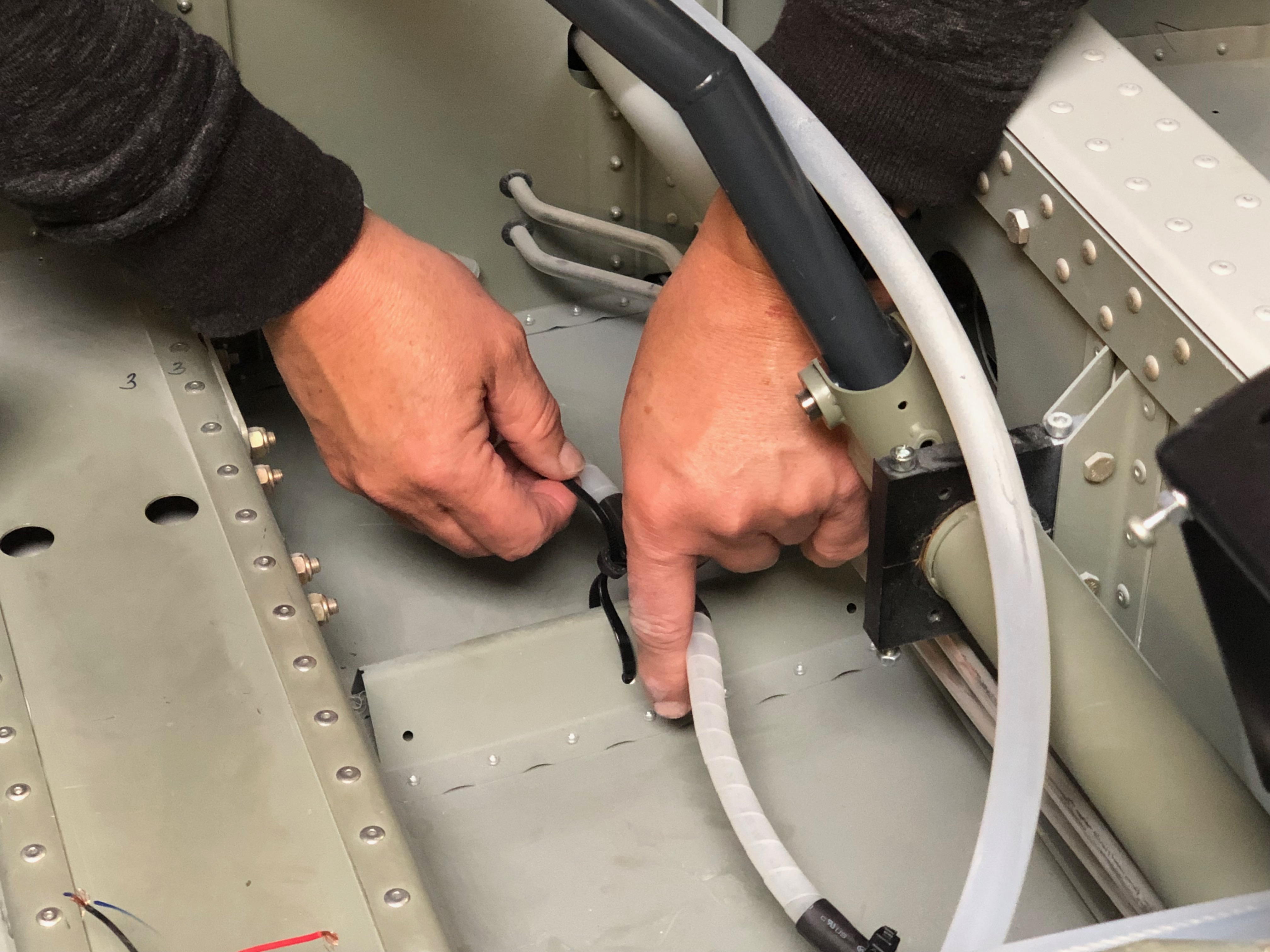
The tubing and wrap needs to be held in pace but a cable tie is likely to separate the wrap and clamp the pipe instead so I slipped some heat shrink tubing over the wrap so a cable tie holds the wrap and doesn’t clamp the pipework. Seems a good solution.
Anti crush inserts are added to the end of the pipes to stop the pipe collapsing when the nuts are tightened.
The nuts are tightened and a heat gun is used shrink the hear shrink. A cable tie is used just to prevent it moving.
Cable tie stand offs will be used to secure the pipe work onto the cabin floor. The holes are opened up with a 5mm drill first.
As I’ve said before, this job is very fiddly, you need several pairs of hands and there’s not a lot of space to manoeuvre!
But eventually it all comes together…
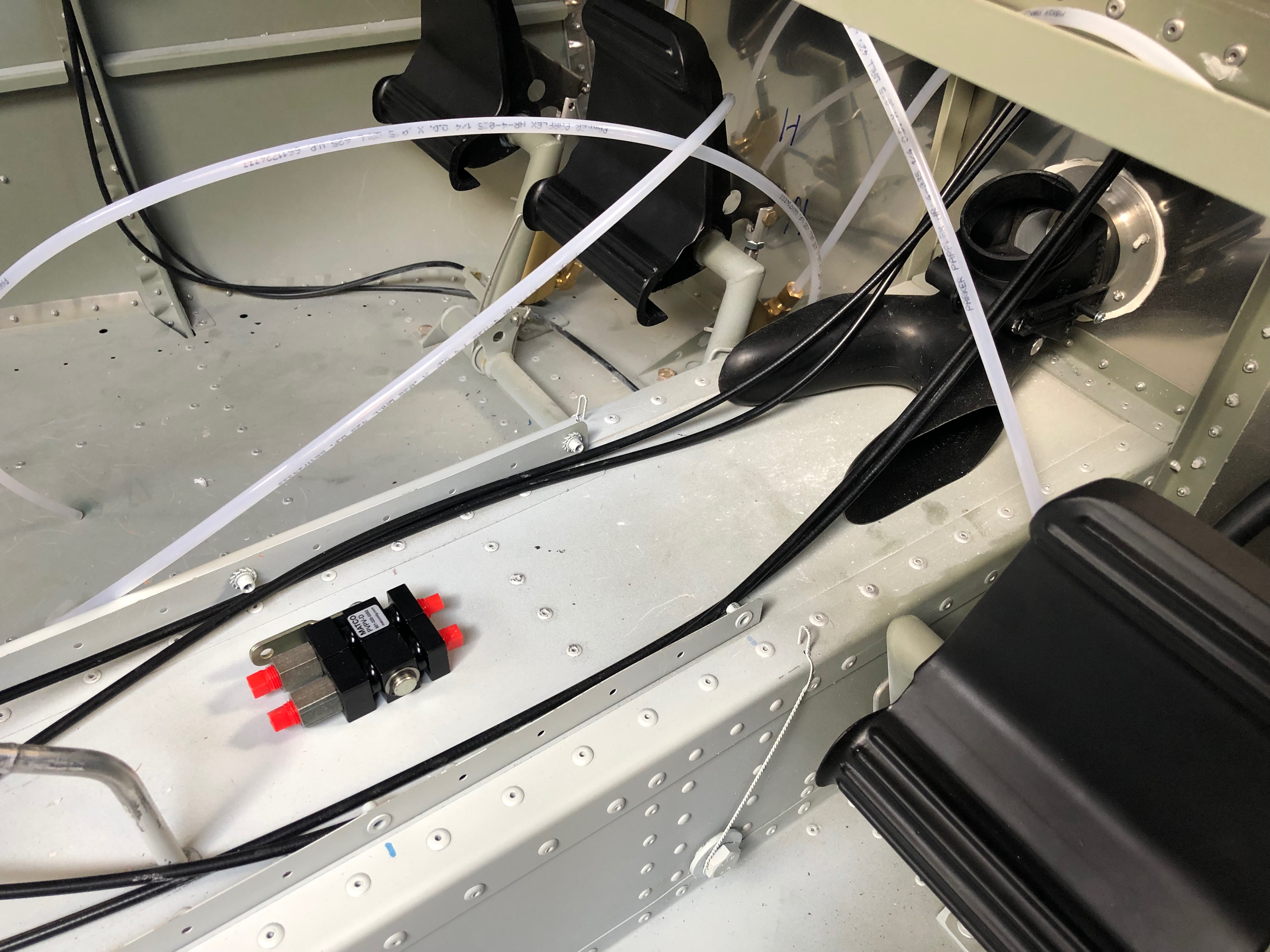
Installation of a cable tie stand off used to secure the pipework.
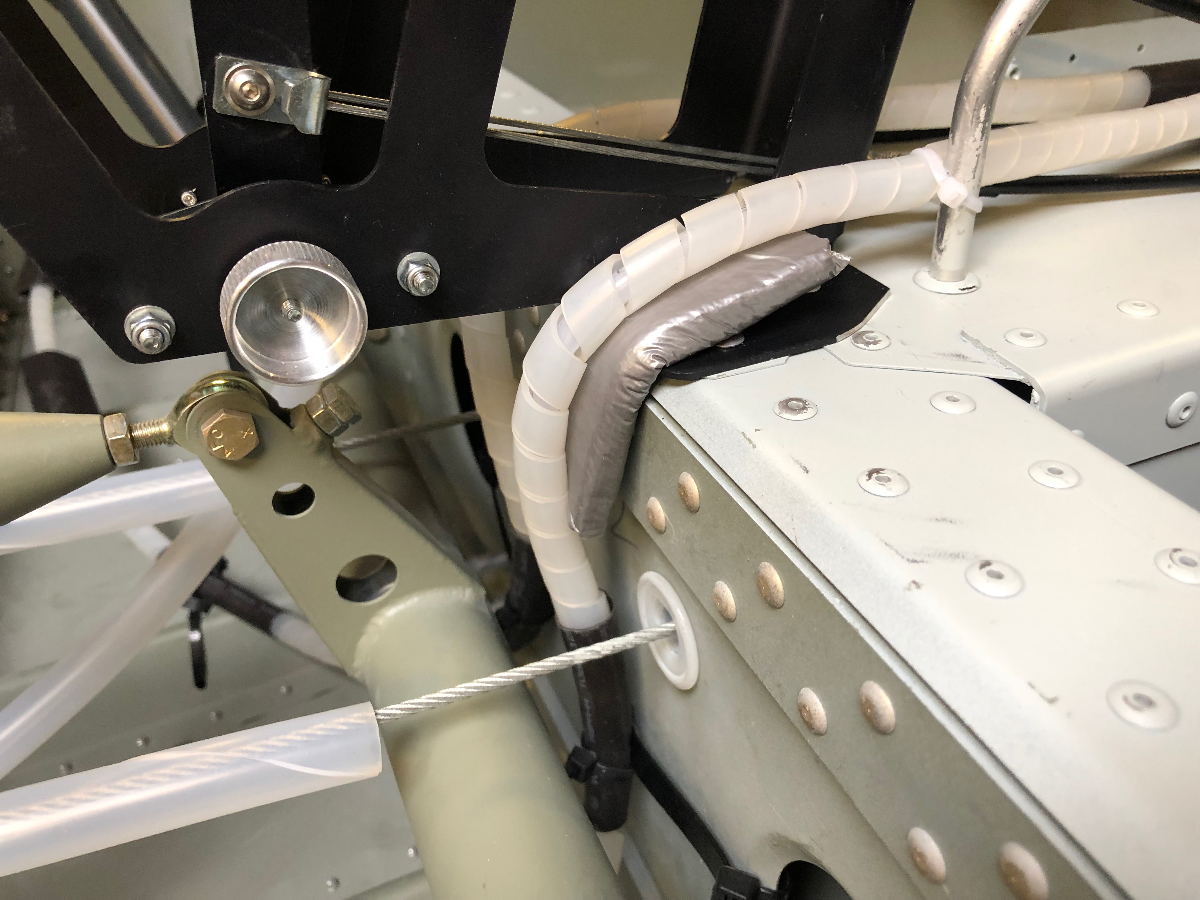
Looking at the pipe runs I found a couple of places where there is a chance of chaffing and possible pipe failure. I’ve secured a couple of pads over a sharp edge that should prevent failure in service.
A jubilant smile – it seems that this stage has taken ages to complete but Karen’s help today has really paid dividends.
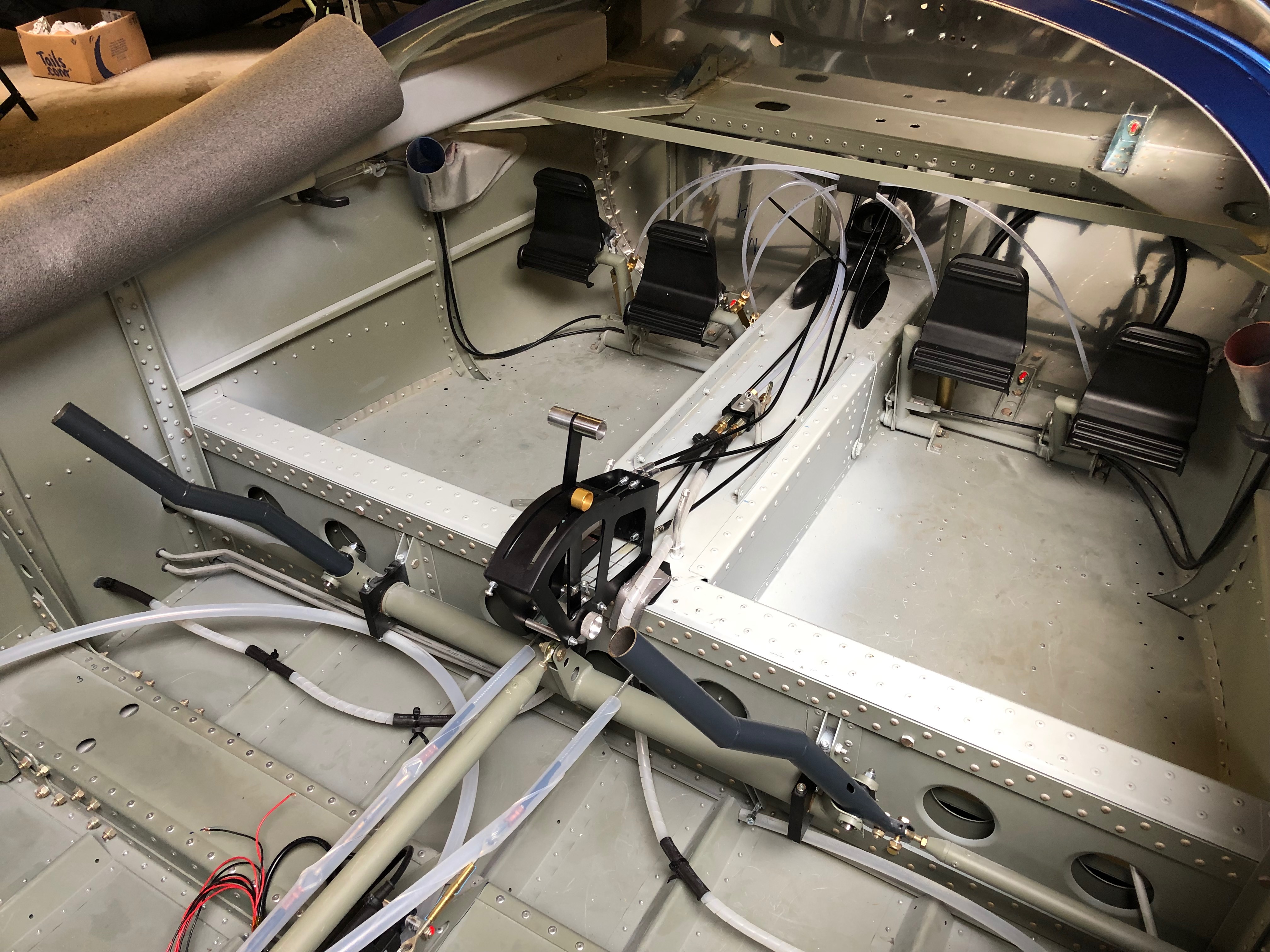
The finished brake pipework in the cabin, just need to run the pipes to the brake callipers which i’ll do on Monday.
Continuing the brake system installation that has turned out to be time consuming and a little frustrating at times as the brake pipes are so rigid that they are difficult to handle.
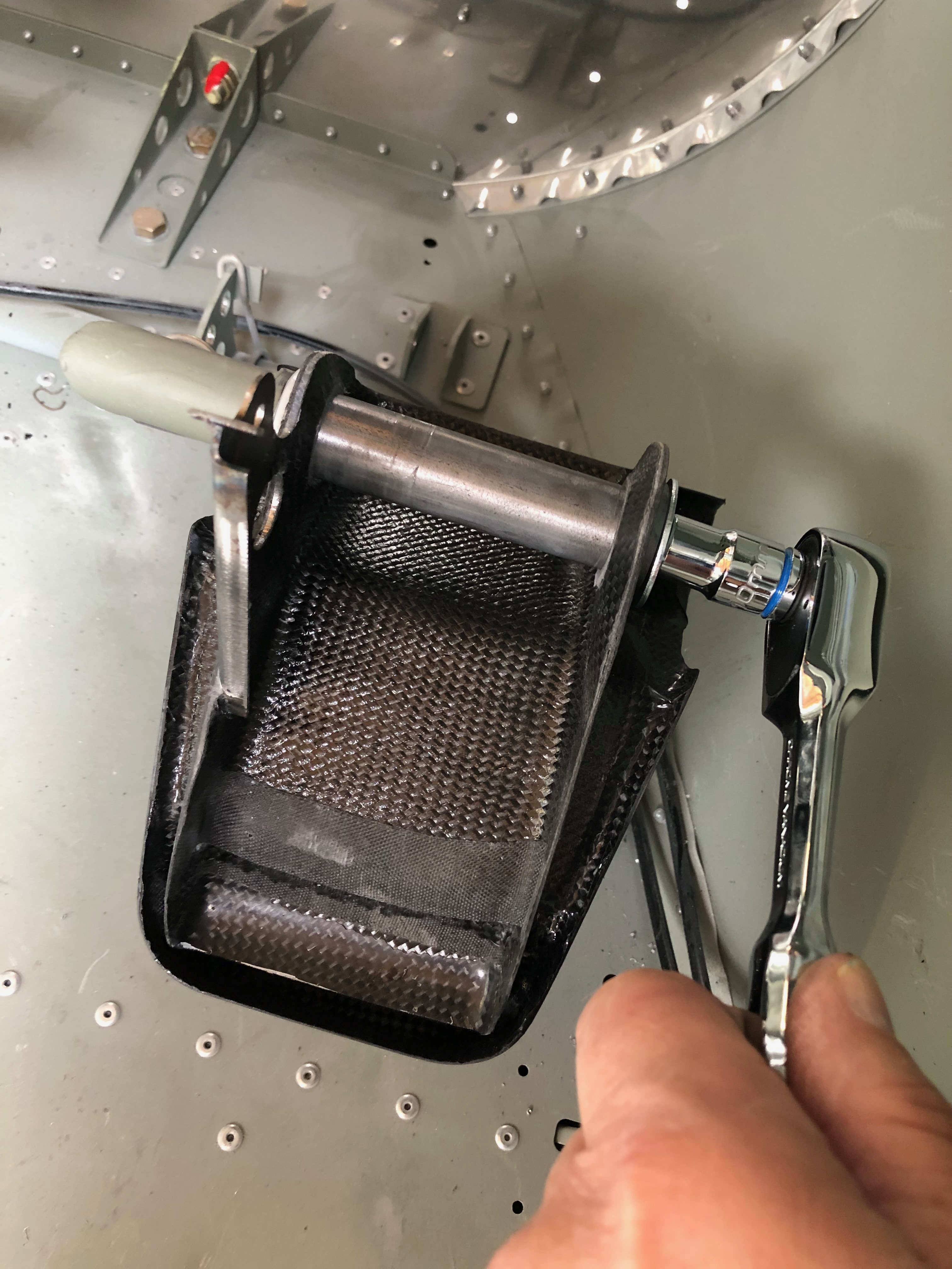
The tunnel is positioned to see how the park brake unit would sit on the airframe.
There is a service hatch on the tunnel moulding that allows you top access the pipework and park brake actuator when required.
All 1/4″ NPT brake fittings require Loctite 577 to seal the threads before fitting.
The complete unit ready for installation.
6mm holes are drilled for a couple of M4 rivnuts that will secure the park brake actuator.
The unit is sandwiched between a couple of pieces of anti-vibration rubber and an aluminium top plate and the secured with a couple of M4 x 40mm cheese head screws.
The installation so far. Such a straight forward piece of work but it’s taken ages to get this far.
Now the park brake unit is in place the pipework to the disc brakes needs to be run. The pipe is very rigid but it becomes pliable with some heat which allows it be moulded more easily.
The rigid pipe needs to be protected with a cover so I’ve used some cable spiral wrap which seems to work well.
Today’s saw a continuation of the brake system installation which has turned out to be quite a complicated, fiddly and time consuming task.
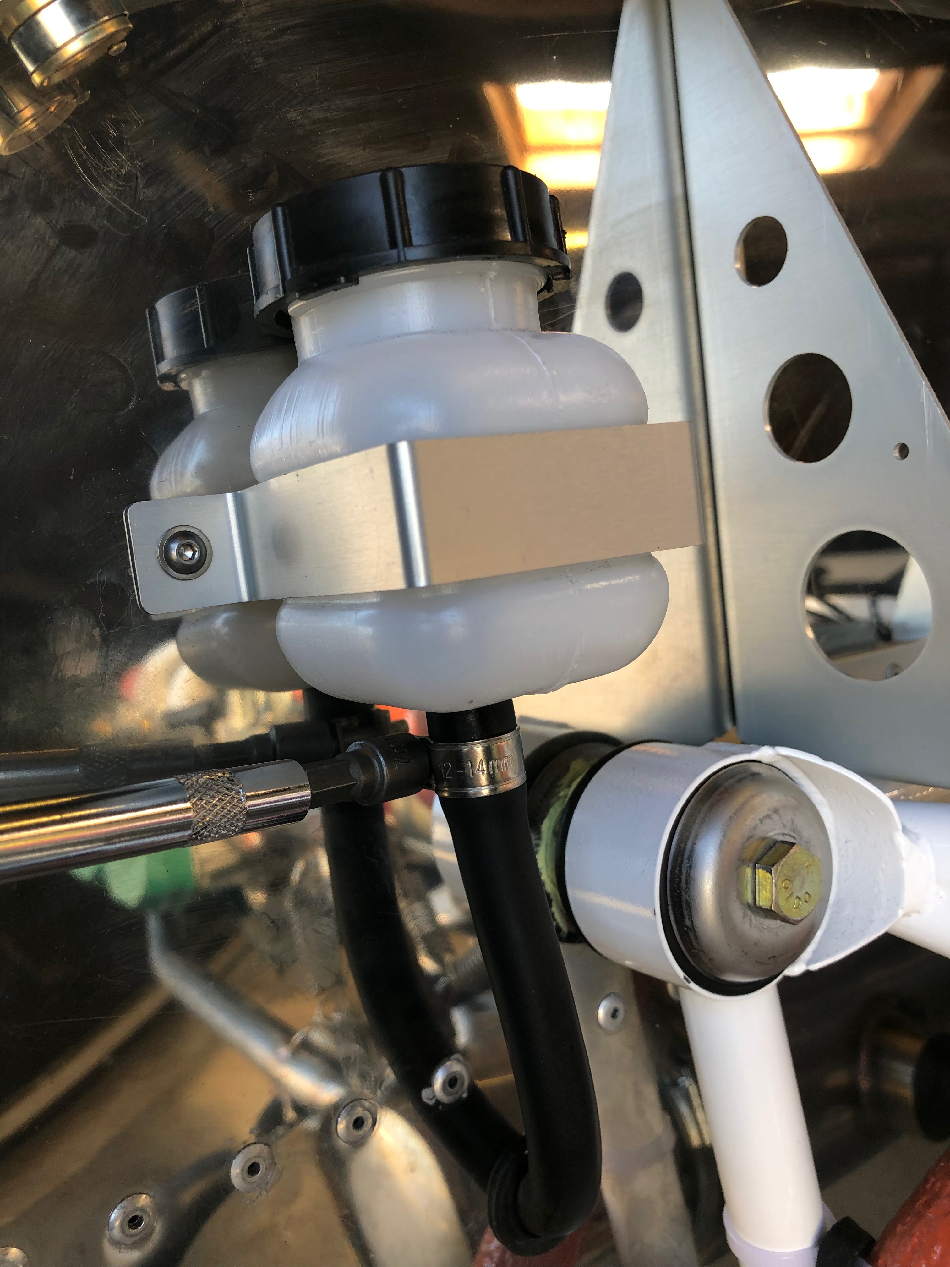
I wasn’t 100% happy with the installation yesterday as one pedal was tight on its shaft and there was slack in the top mount to the master cylinder. I decided to use a different set of washers which removed the slack and made a much better installation.
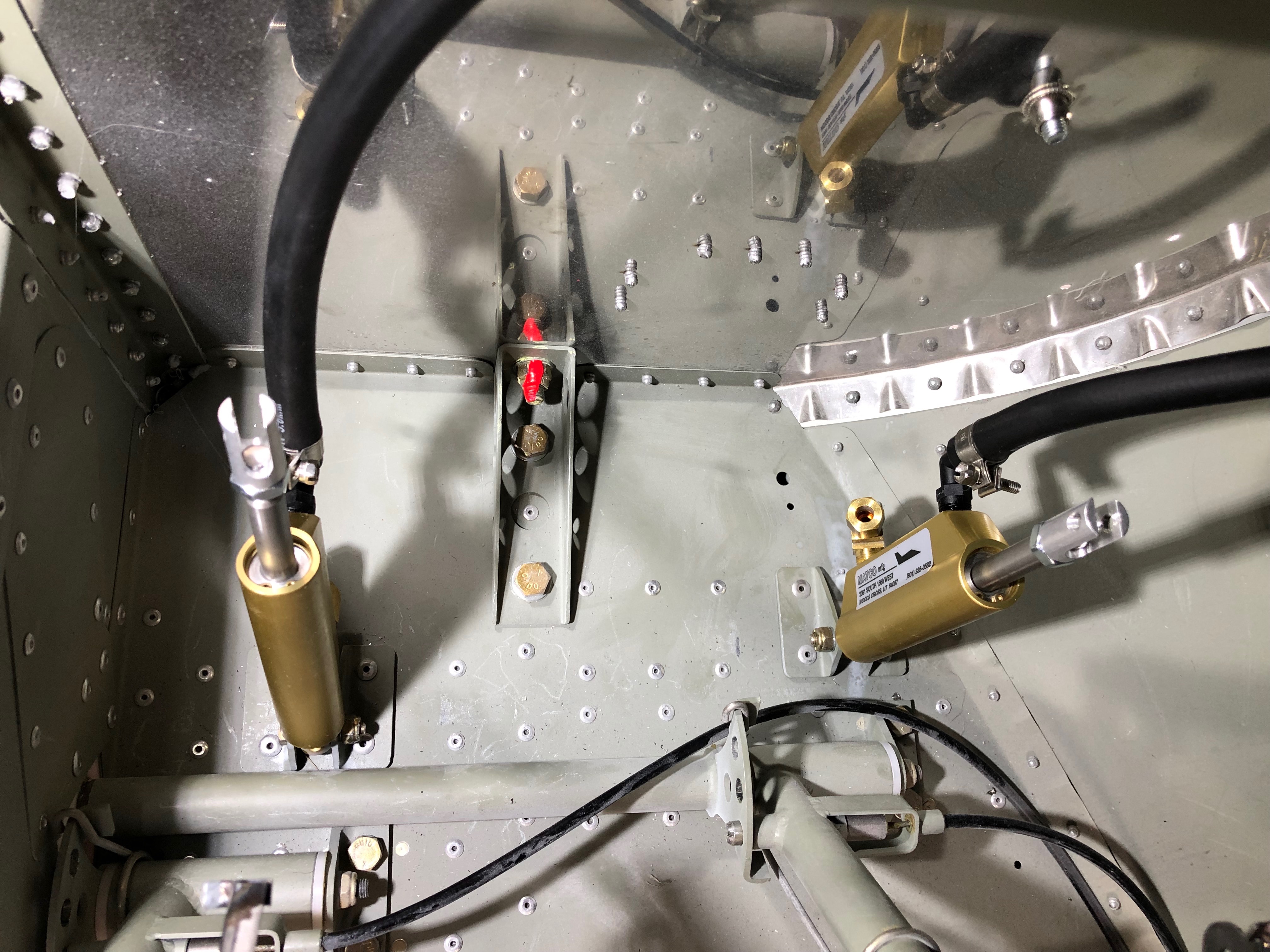
Now for the piping. The brake reservoir to master cylinder hose was installed.
A stand off is used to prevent it moving when the brakes are operated.
The brake reservoir bottle is connected.
The support bracket has a lining of rubber applied to make sure that the bracket doesn’t damage the bottle itself.
The bottle is clamped to the firewall and the pipe clamp is tightened.
The installation so far. Doesn’t seem much for a one and half days of work but the installation needs a lot of thought to make sure that the pipework and pedals aren’t fatiqued when operated in service.
Tomorrow’s task will be to install the park brake and the remaining brake pipes.
As I’ve now ordered the avionics for the build I thought I’d make a mock up of the panel and see what it looks like in the plane.
One of the jobs left over from the fuel system install was to fit a 1/8″ NPT blanking plug in the top of the gascolator. Luckily Ian Daniels had one spare. Loctite 577 was applied before tightening.
Next up was to start the install of the brake system. The picture shows the components that make up the system. I ordered hydraulic brakes with the parking brake option.
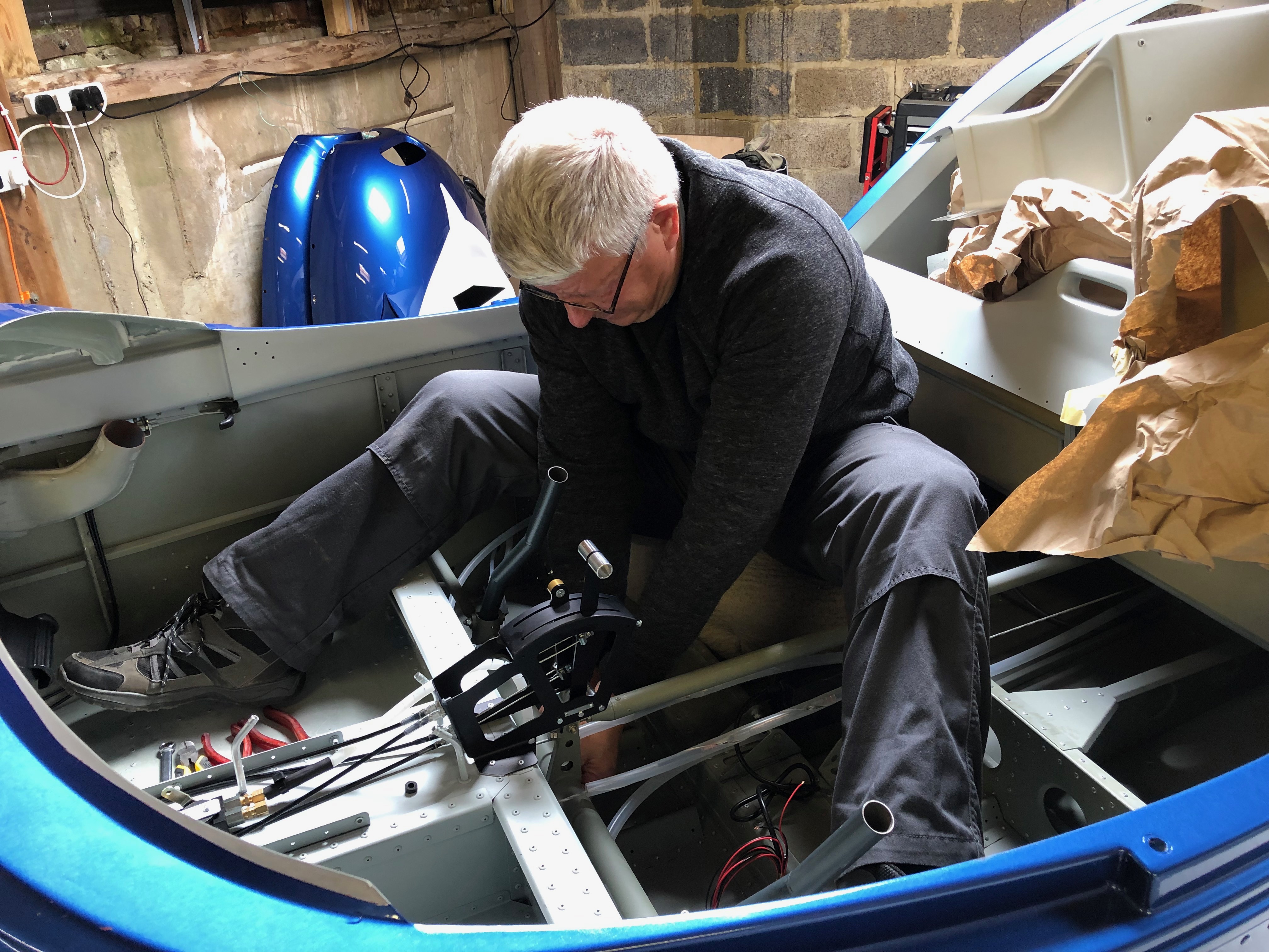
The brake sub assembly is made up outside the plane as it’s quite difficult to work in the front of the fuselage in the space behind the pedals.
The master cylinder fittings are added and threads sealed with Loctite 577.
The brake pipes are cut to size and added to the fittings to test the assembly looks right.
The brake pedals are added and secured with an M6 bolt and 30mm washer secured with Loctite 243.
All four rudder pedals in place.
The master cylinders are fitted next using a m3 bolt and nyloc.
After some exciting skiing in Val Thorens it’s back to work. Whilst I was away I planned my weeks ahead based on what’s left to do. Some small jobs to get me back into the groove.
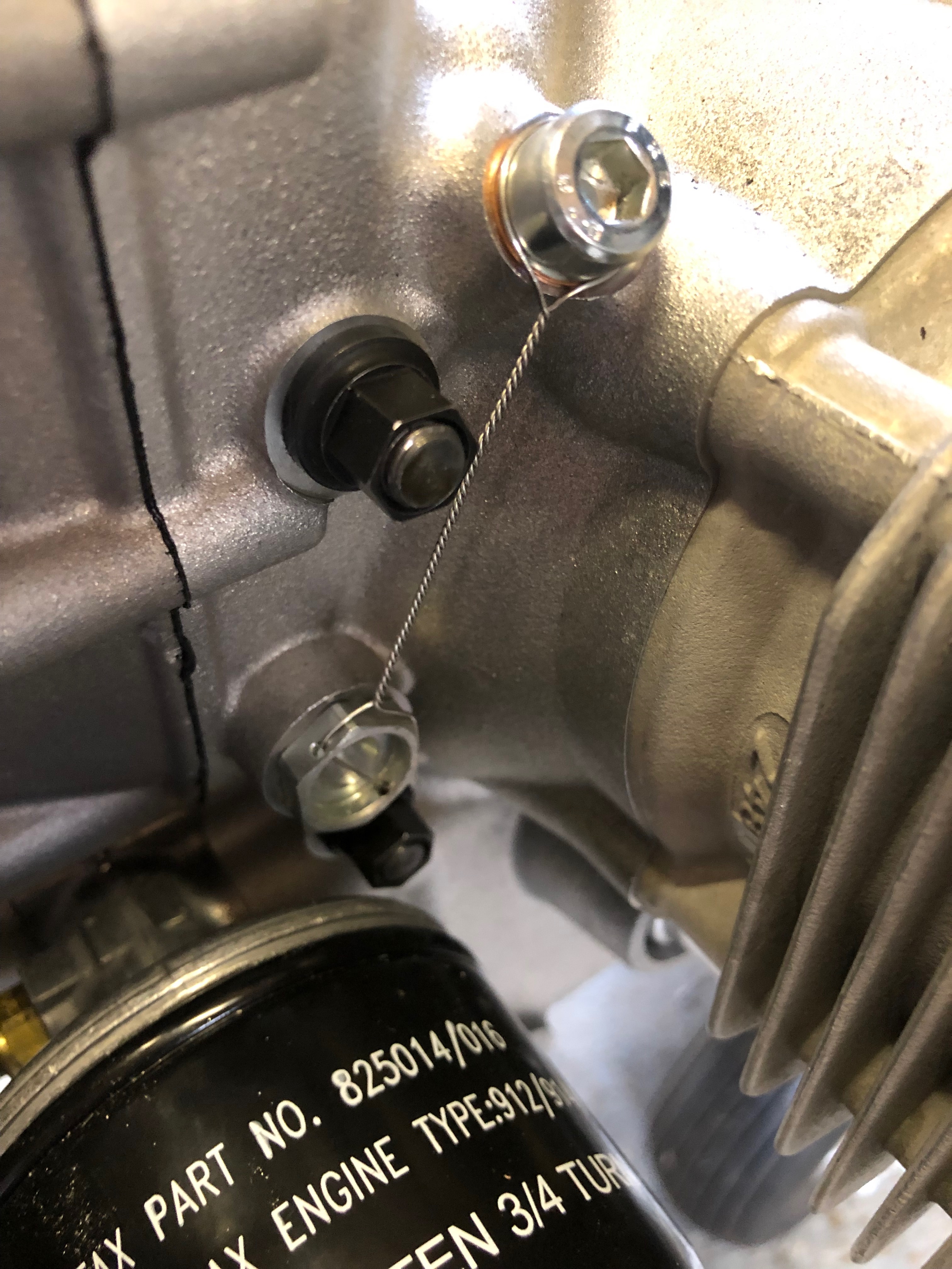
The magnetic oil plug needs to be checked for debris. If any large pieces of metal are stuck to this it’s an indication that there is a problem with the engine.
Once checked the plug is refitted and locked to prevent it from coming loose whilst in operation.
The oil drain banjo underneath the engine also needs to be wire locked.
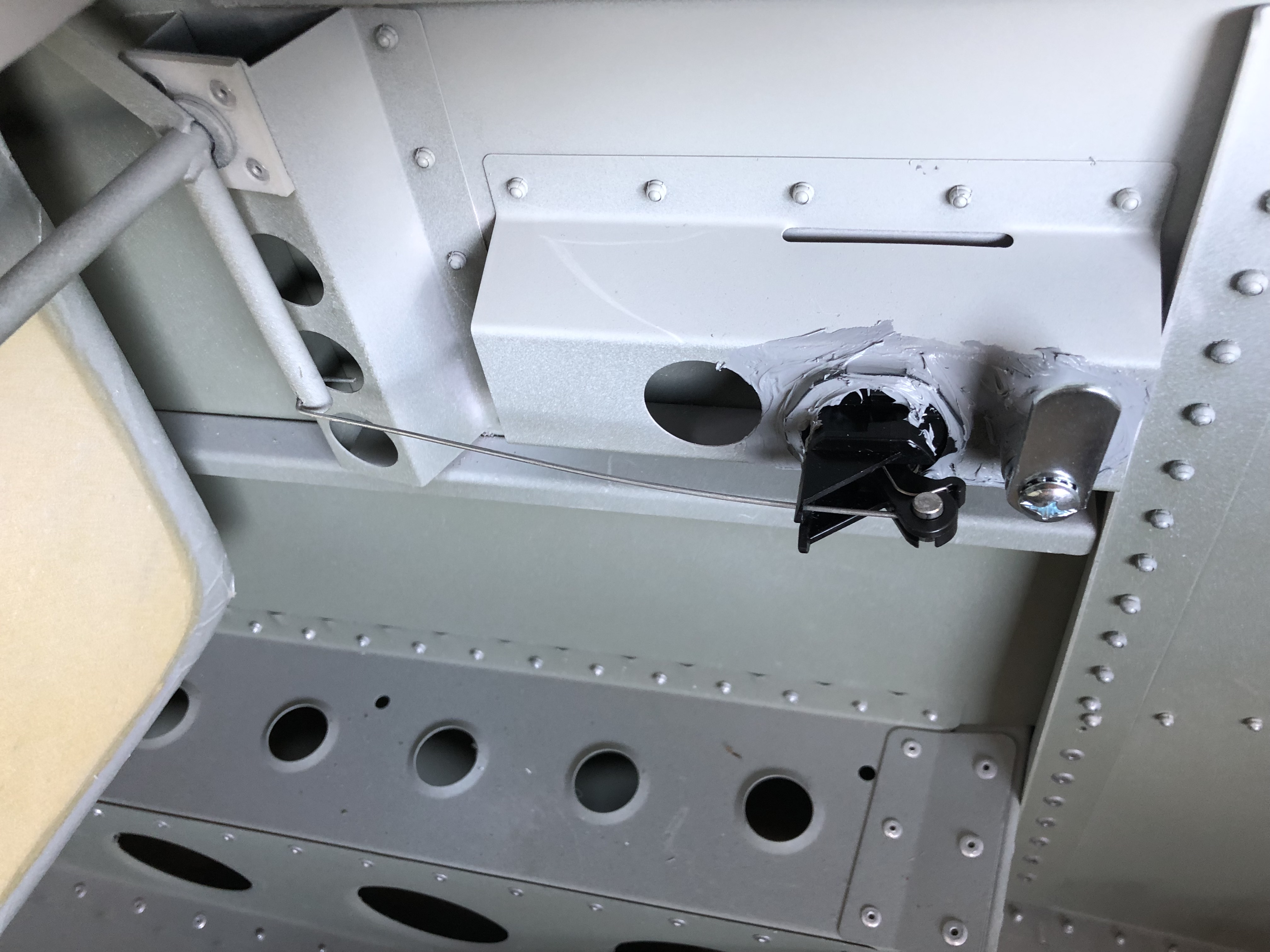
A job leftover from fitting the canopy locks is installing the centre canopy release mechanism.
Holes marked and drilled.
A rivnut is installed and the mechanism is secured. Once the interior panels are fitted the operating wire will be fitted.
When Chris came down he helped me install the electric aileron trim servo. Now it’s time to install the Elevator trim mechanism. Chris had already attached the clevis, pin, split pin and had cut the threaded rod which cuts some of the work I have to do.
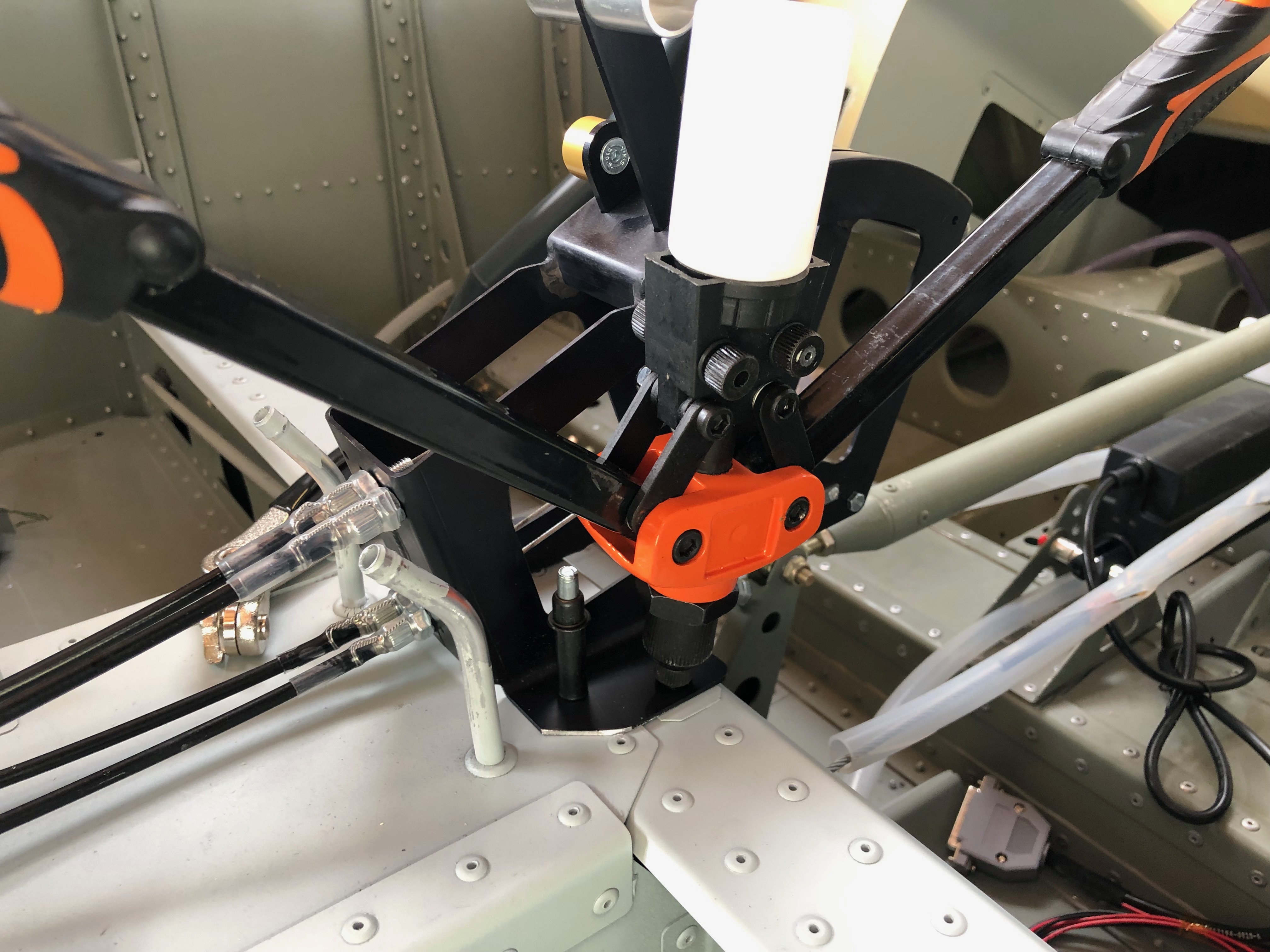
The first thing that needs to be done is to set the trim motor to its extremes so it can be set at midpoint.
The midpoint is 8.5mm which is set by connecting to a 12v battery to move it to that position.
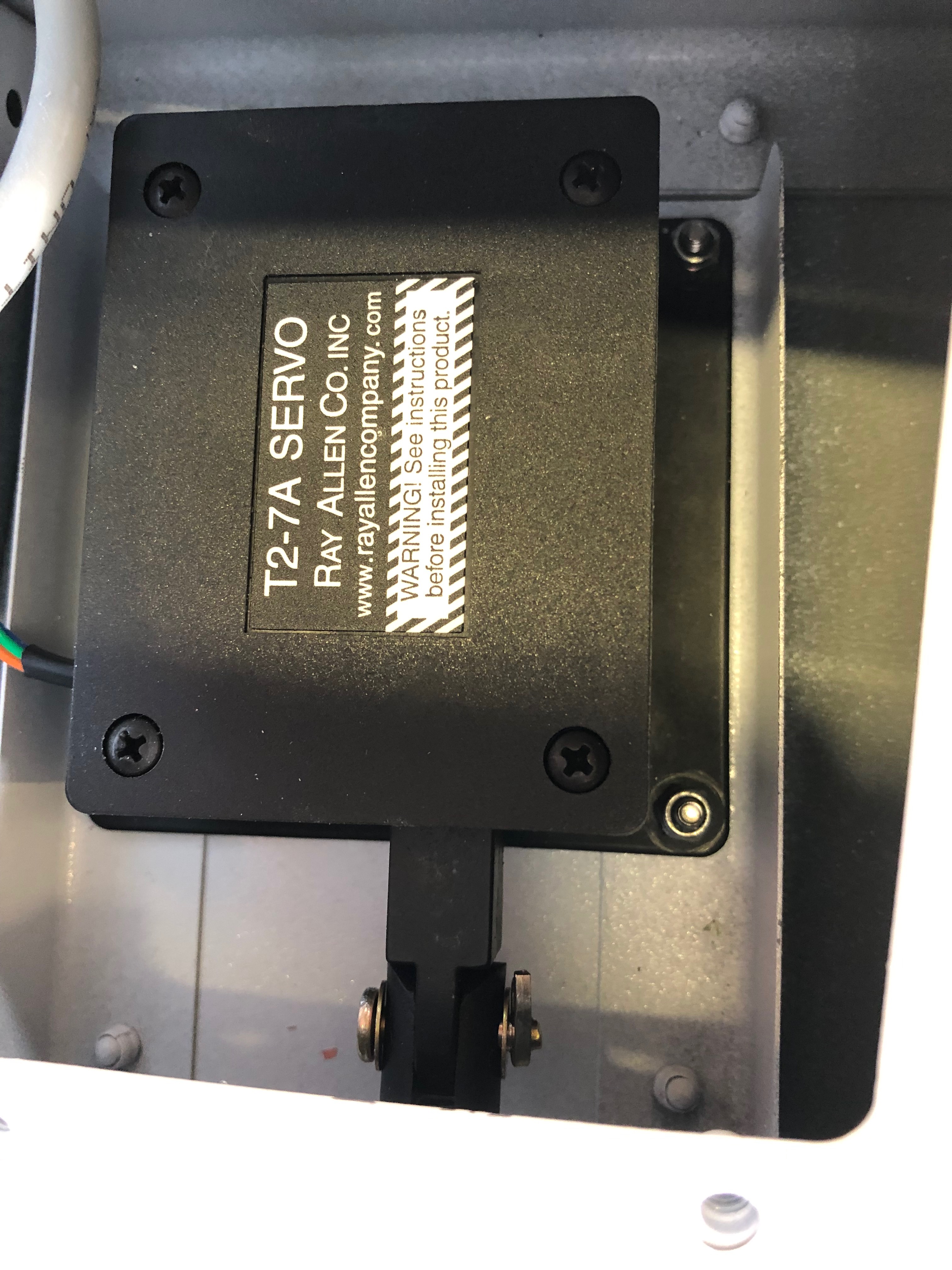
The servo is temporarily installed with Clecos, the other clevis is attached and adjusted so the trim tab is inline with the elevator.
The Clecos are removed and M3 screws, nylon washers and nylocs nuts are used to secure the servo.
Once correctly adjusted the pin and clevis is secured with a split pin.
Today focuses on finalising some of the work I had already started but was waiting on parts.
First up is to rivet the throttle into place.
A view of the throttle installation from the top.
Next is to replace the 5/16″ bolts that were found to be damaged.
Once tightened the nuts are marked with torque seal to indicate any movement in service.
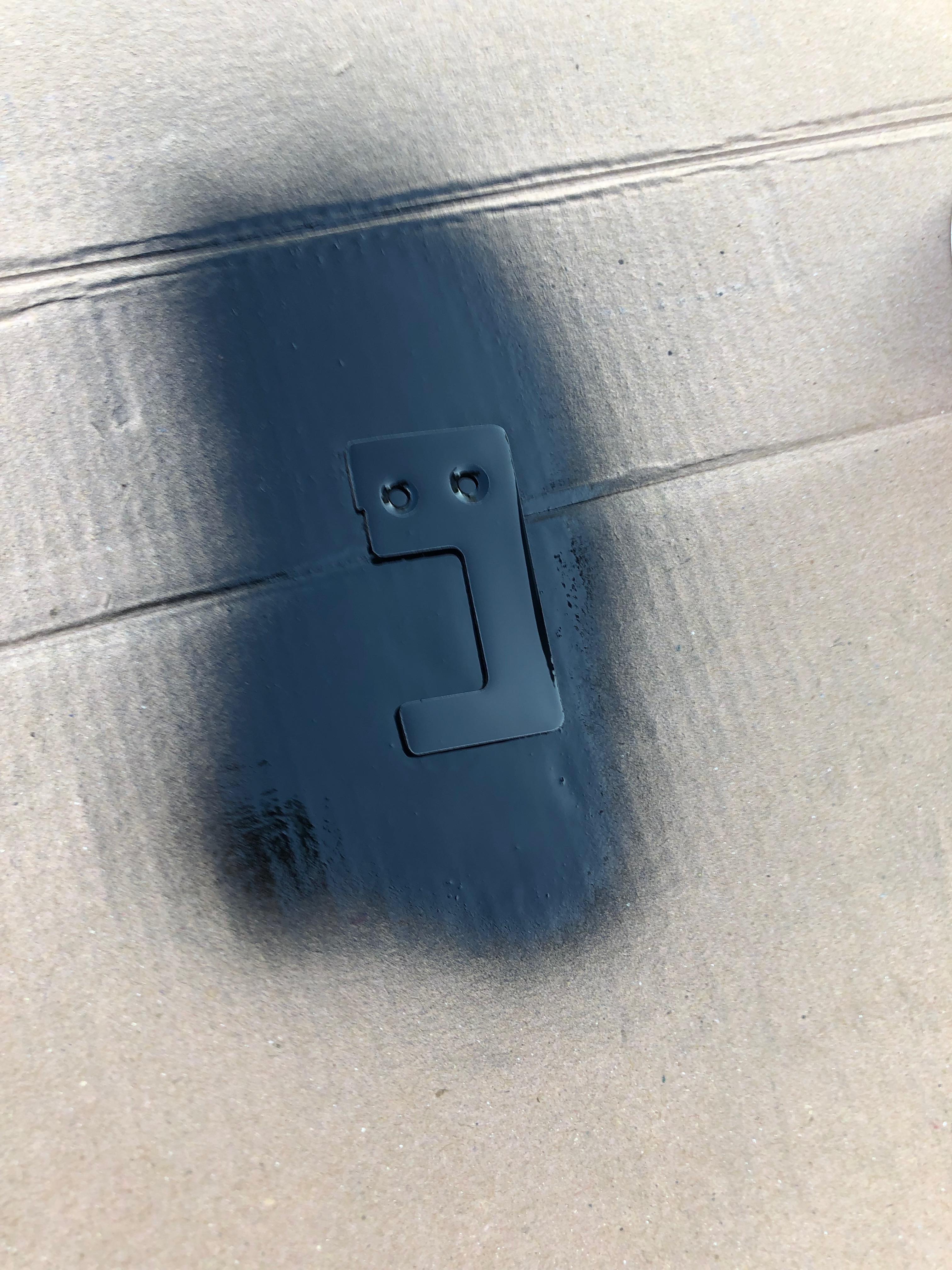
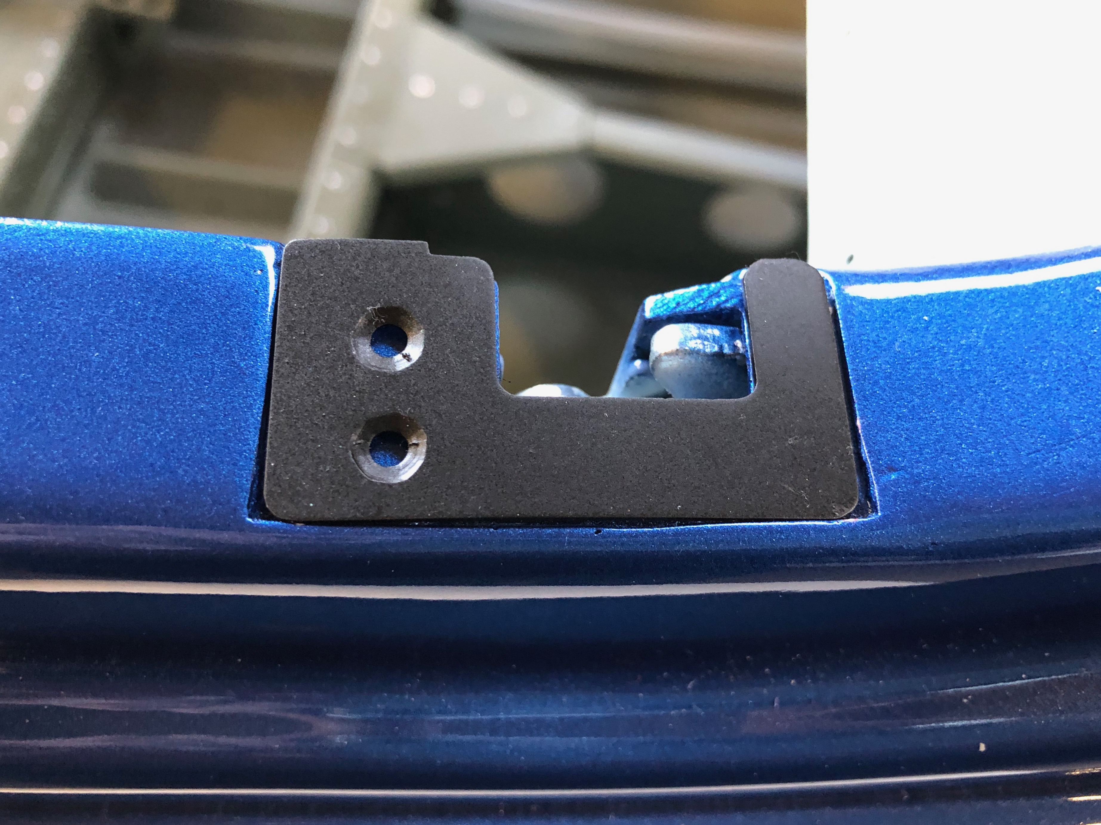
The canopy latch striker plates are riveted into place.
And the spring return plate is riveted into place and the spring connected.
The trim motors are normally riveted into place but I’ve decided to use an M3 bolt and nyloc bolt as it will be easier to change should there be a problem.
The wiring needs to be done next but I’ll leave that for another day.
A number of jobs today including some to finalise previously started installations.
The throttle quadrant was cleco’d in position temporarily to allow the cables to be run. This needs to be riveted with 4mm x 15mm rivets which I need to purchase.
The temporary holes were 3.2mm so I’ll open them out ready for riveting tomorrow.
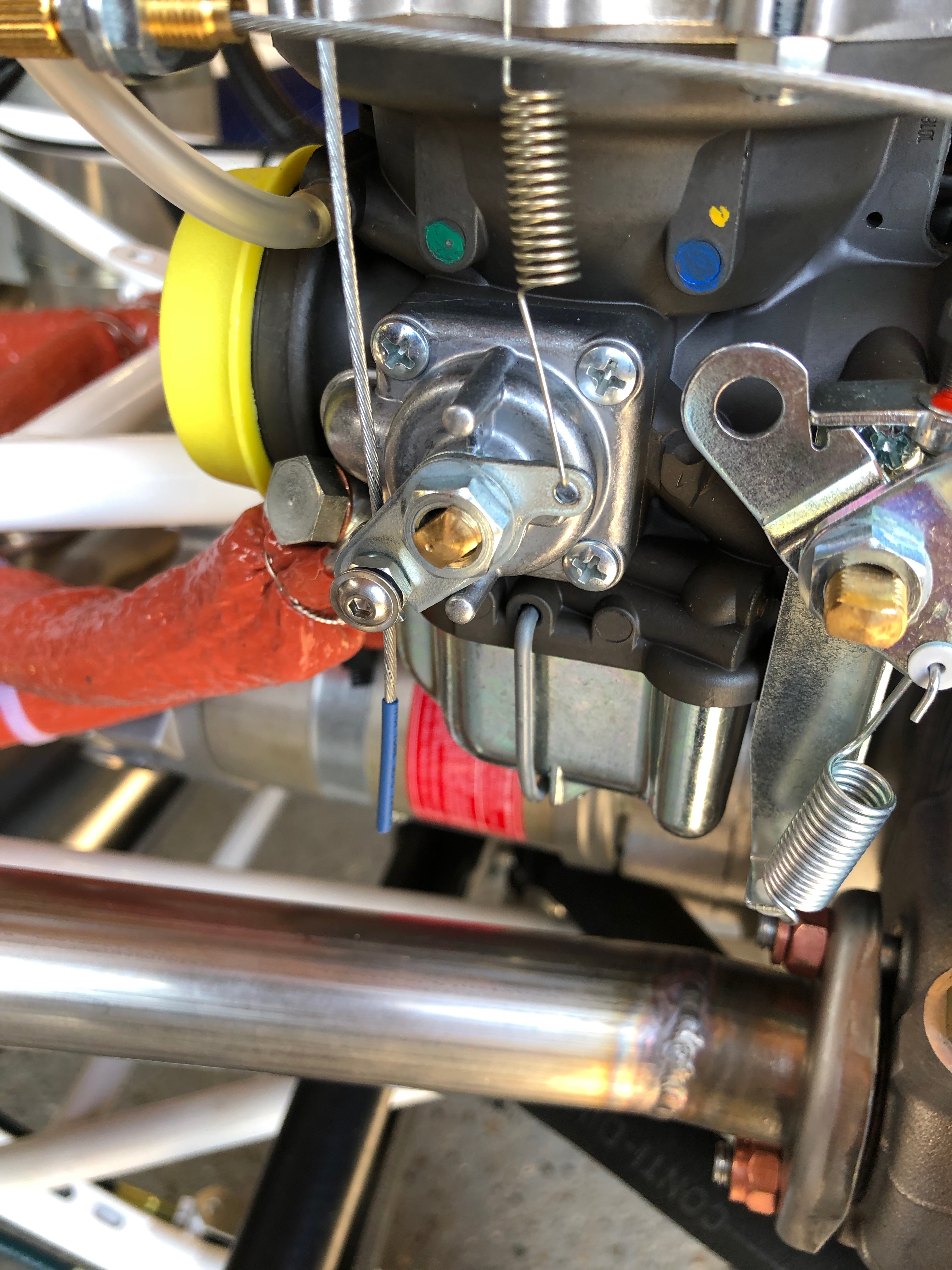
The throttle and choke cables need to be adjusted, tightened and cut to length.
A small piece of heat shrink is put on the end to stop it fraying in service before it is cut to size.
The drip trays are held in position by a bracket at one end and a piece of wire lock at the other. A small hole is drilled in the drip tray to facilitate.
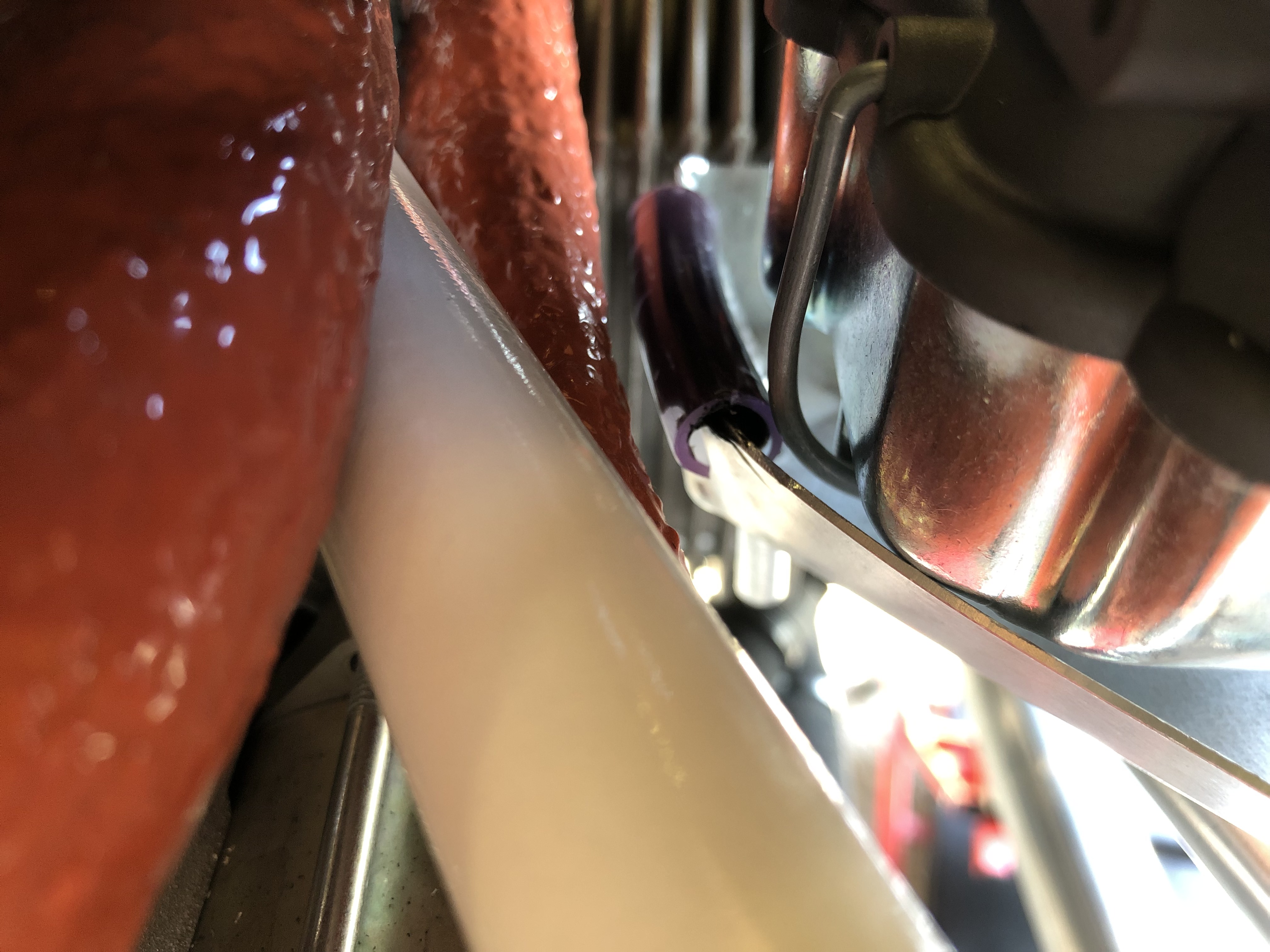
The right hand tray is quite close to the fuel line so a small modification was made to the tray itself and a small piece of plastic tubing secured on the top of the tray to stop it rubbing on the pipe.
View of the final installation.
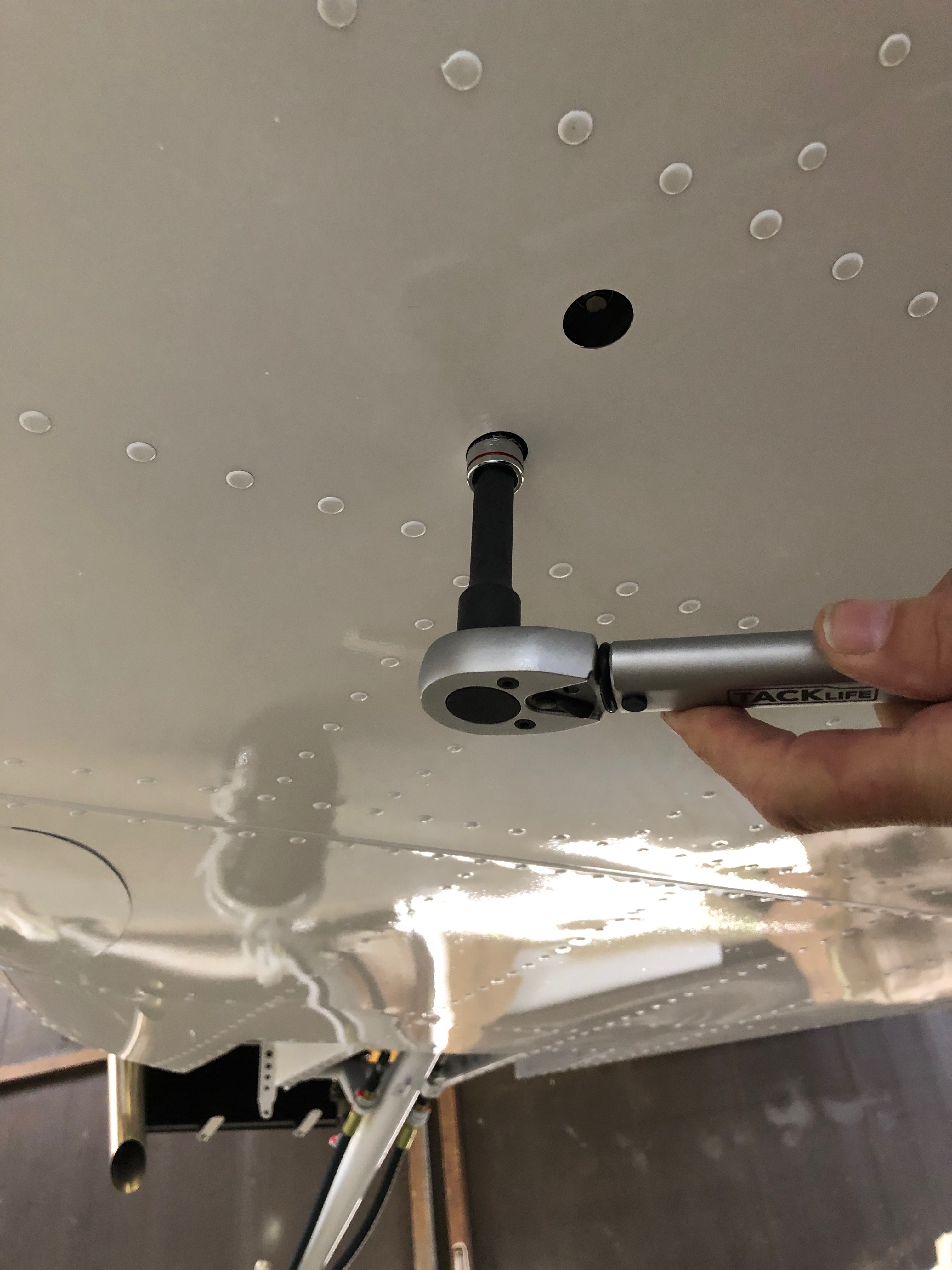
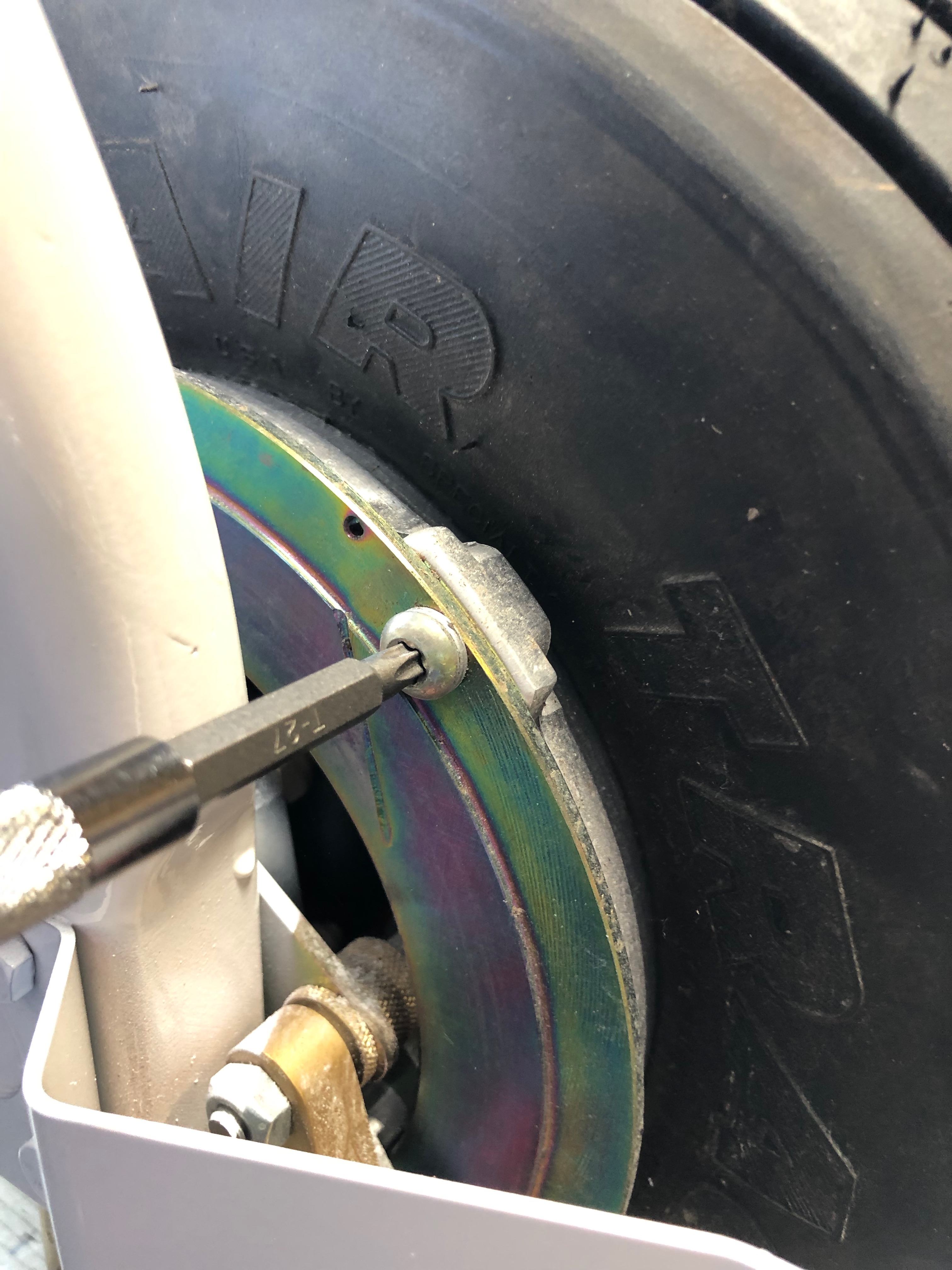
One of the jobs on my ‘todo’ list was to torque the brake disks so the wheel is jacked using a simple wooded jack.
The bolts are torqued…
and marked with torque seal. This will allow me to see if there is any movement in the bolts whilst in service.
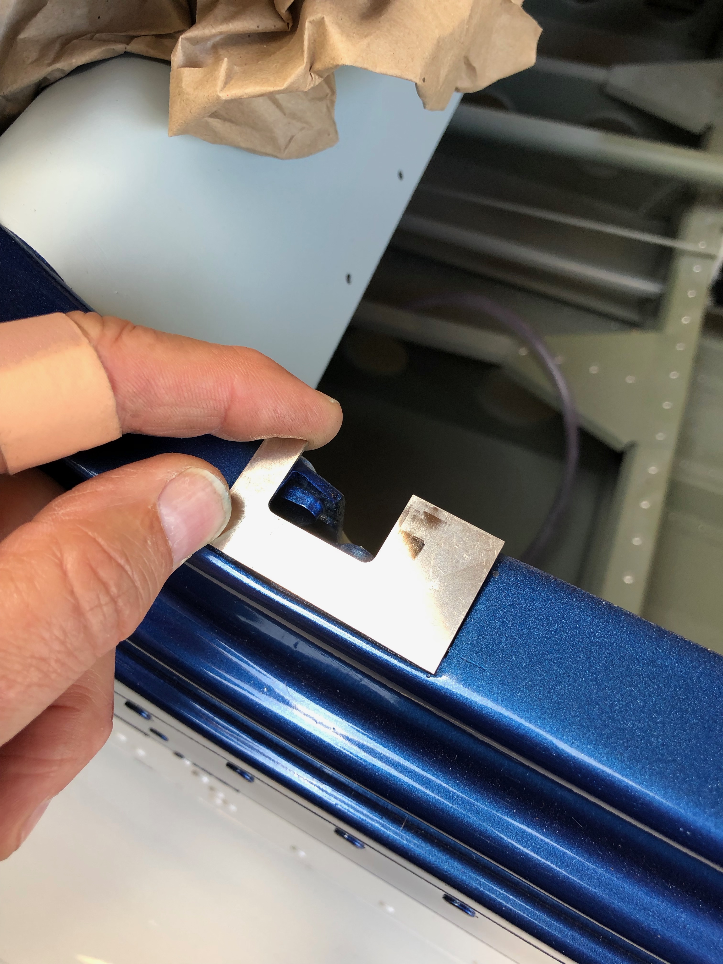
Next job to do fit the canopy locks and striker plates.
Once cut to size, holes countersunk and smoothed off they can be painted.
The striker plate in place ready to be riveted into place tomorrow.
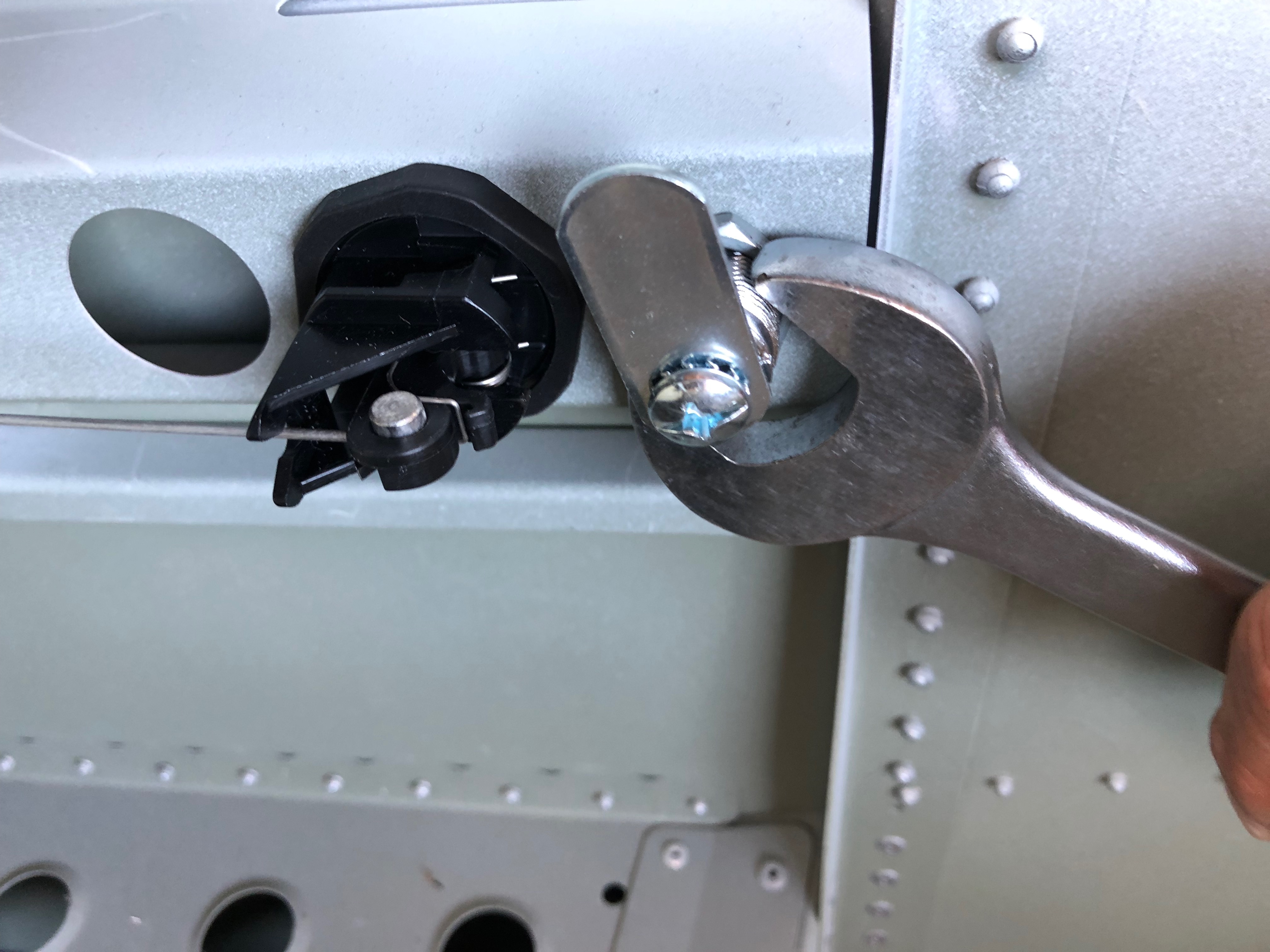
The canopy lock and release are installed and tightened.
The actuating wire is cut to size and fed through the operating arm and finally the installation is sealed with silicone sealer.
Following the build of my Bristell NG5 Kit No. 382 Registration G-MLSY