Category Archives: Engine

Wednesday 11th March 2020 – Transducer Testing

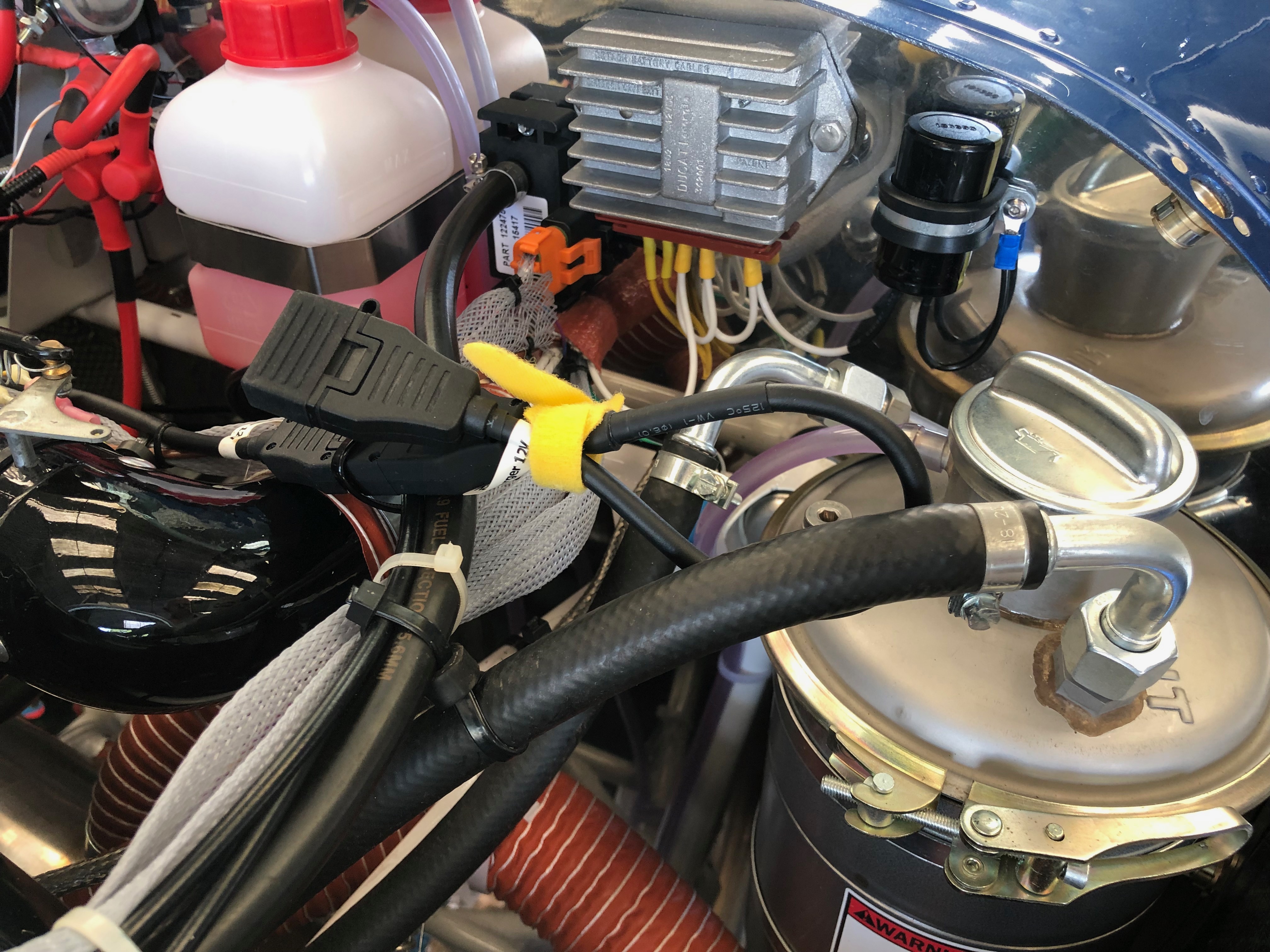
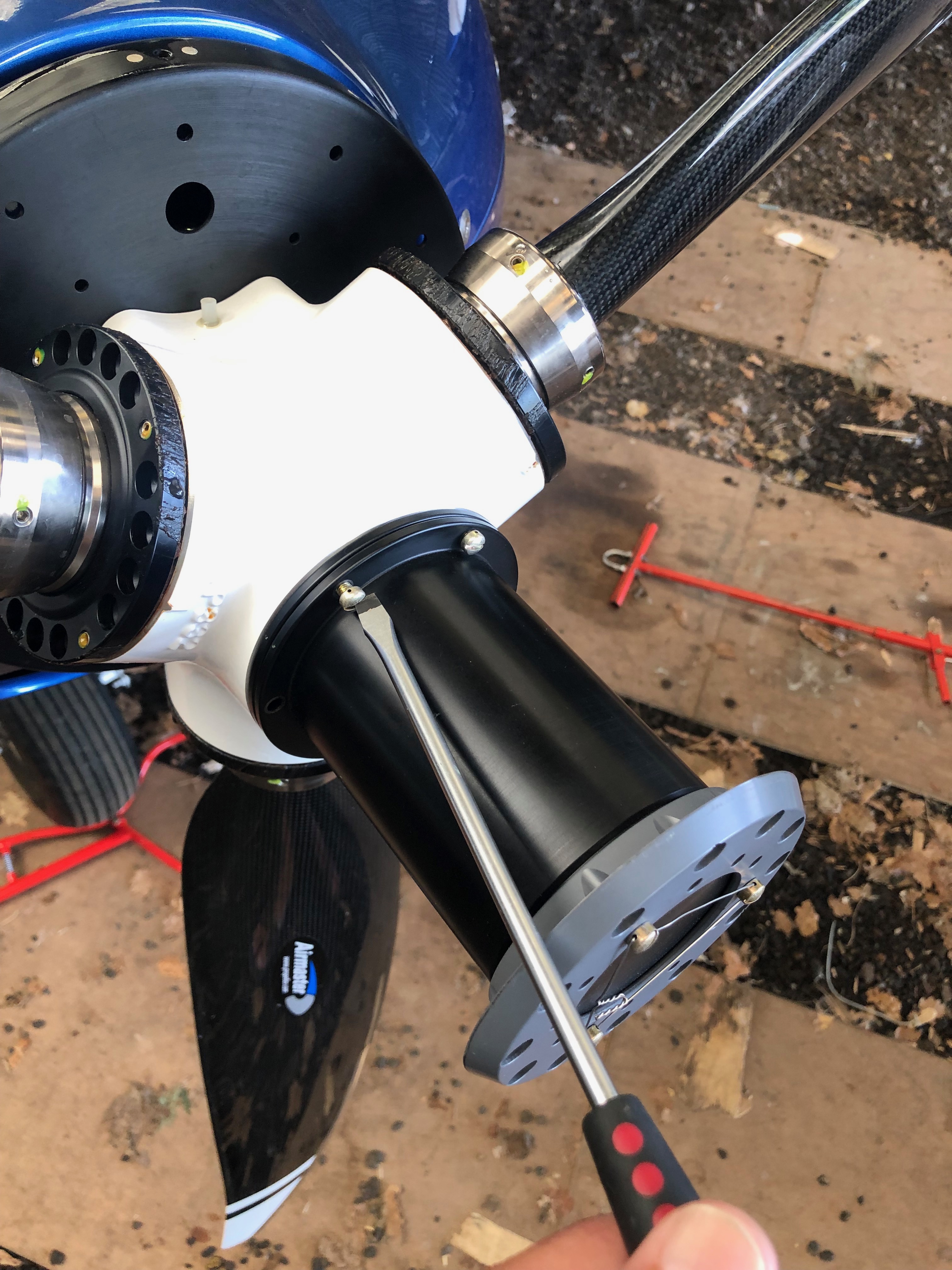
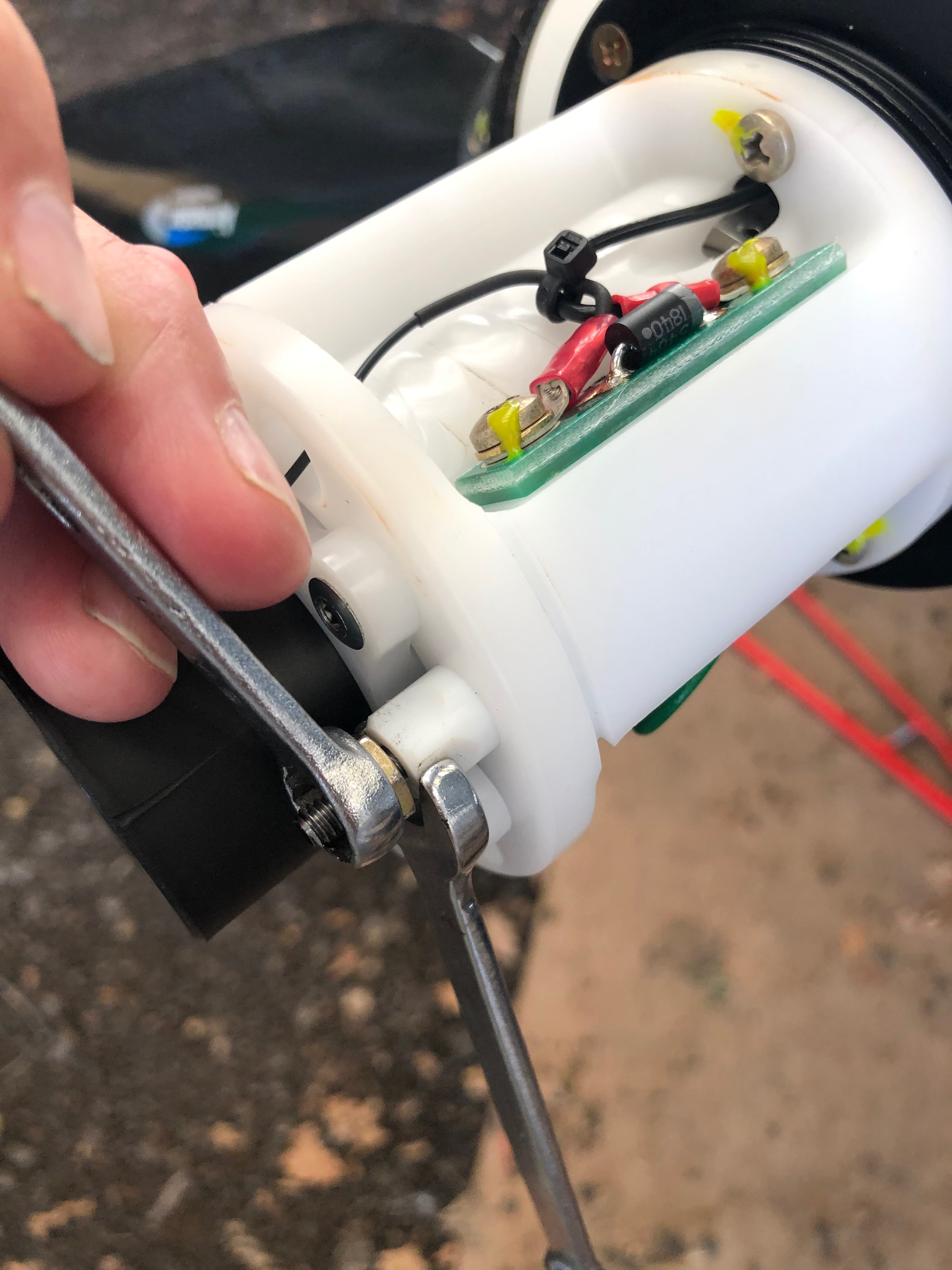
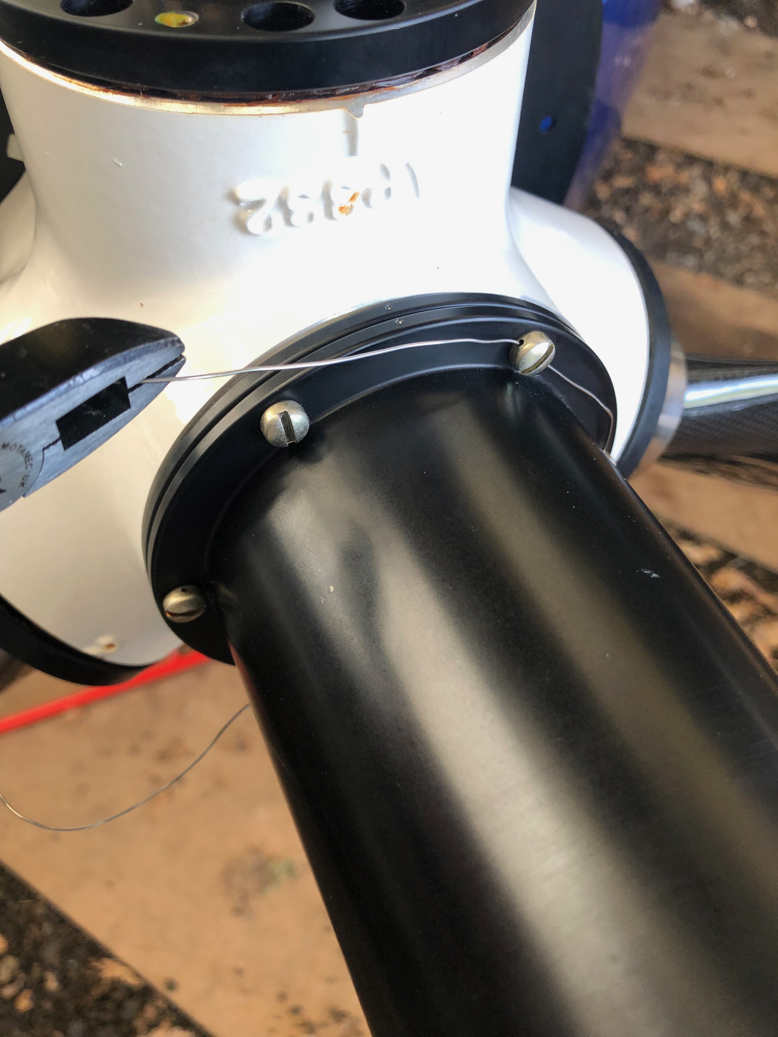
Back from Vienna just before Corona Virus closed all borders! With the transducer installed before I went away I rechecked the installation and carried out pressure testing to ensure there’s no leaks and all seems to be secure.

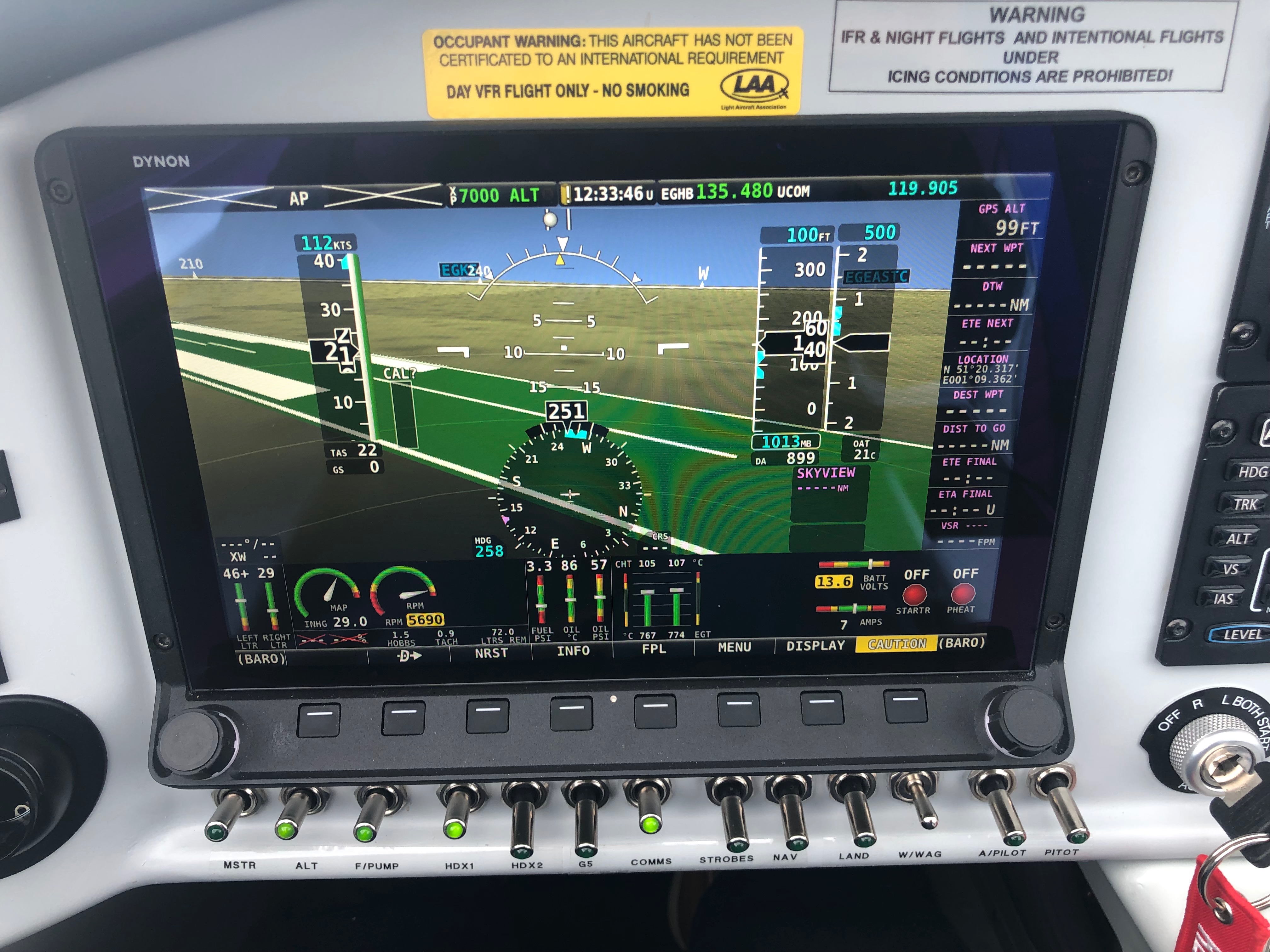
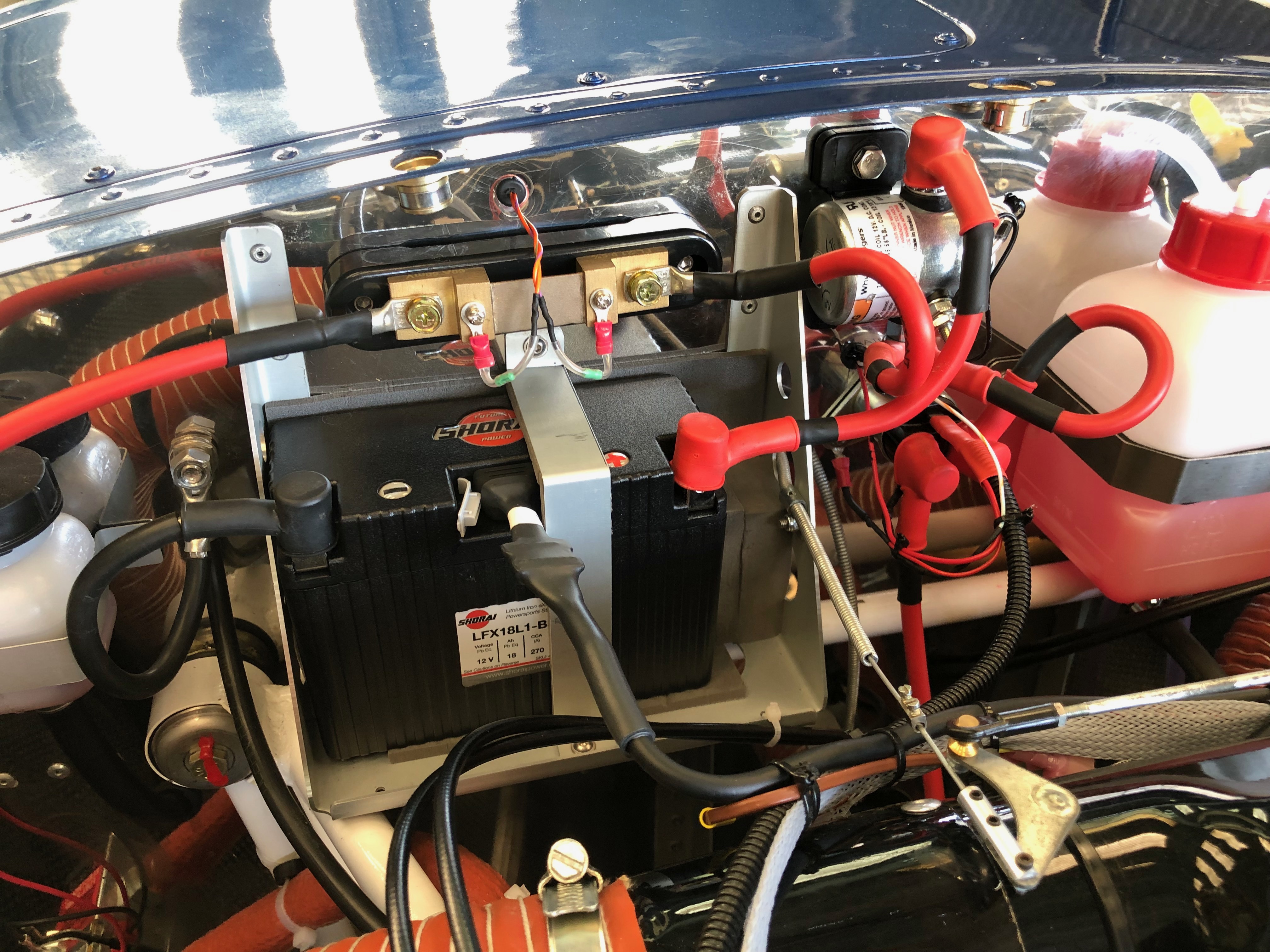
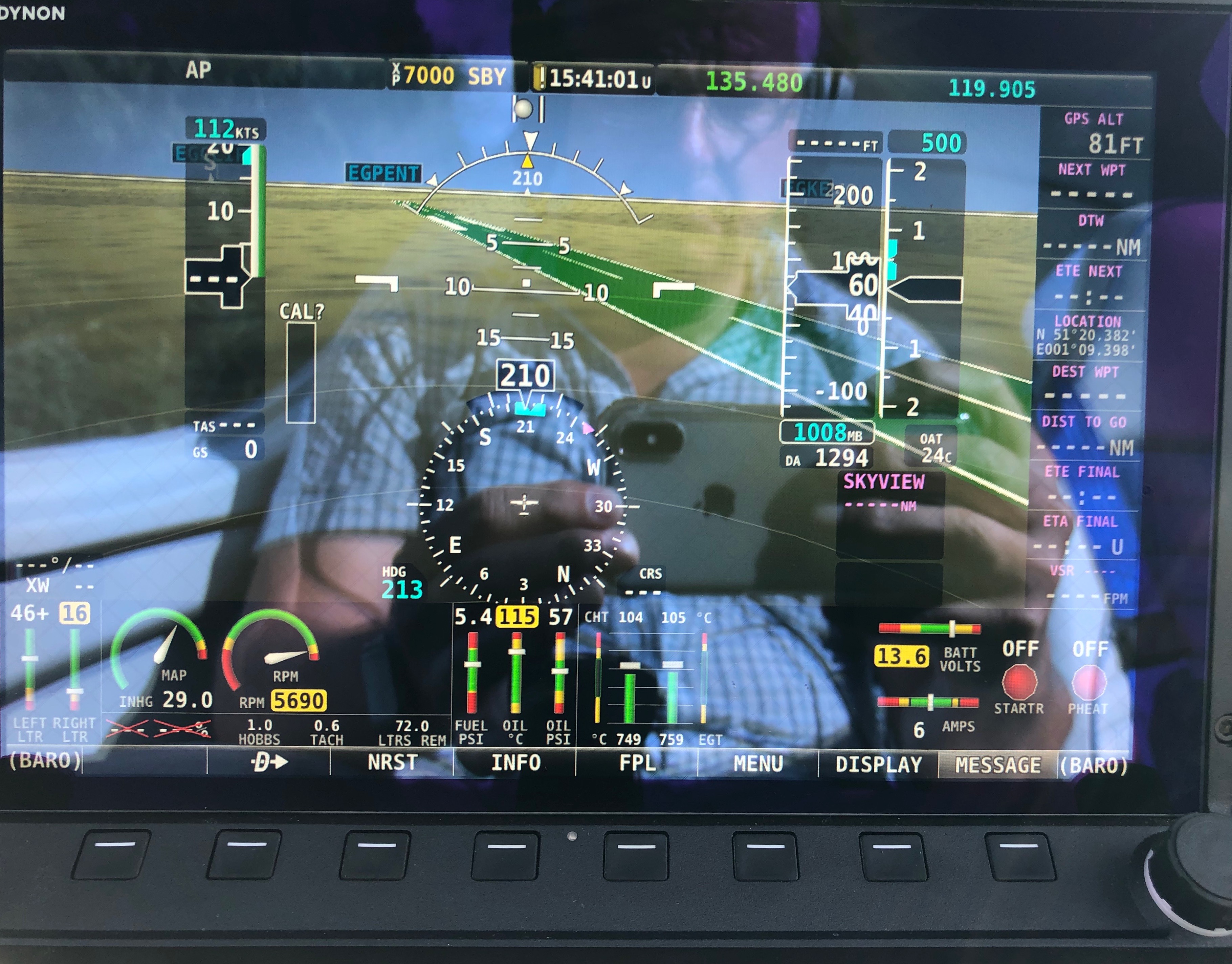
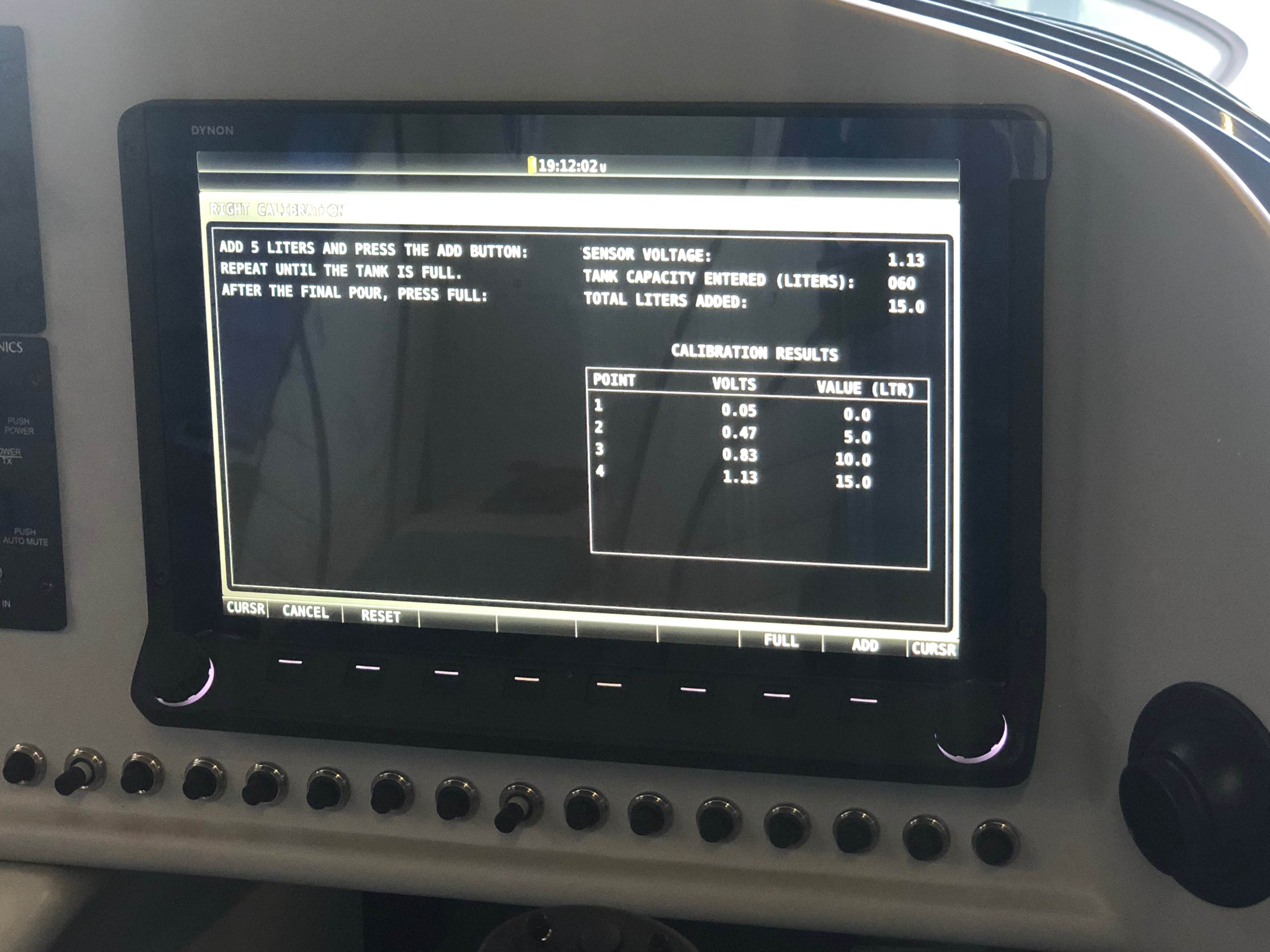
Wiring up the transducer into the EMS220 is straightforward using 3 wires, a 12v supply, signal and ground. The SkyView panels need to be configured with the ‘K’ factor of the FT60 unit. This is the number of rotations per US Gallon. Entering the config screen I found that the SkyView had already detected the unit and configured itself which was handy.

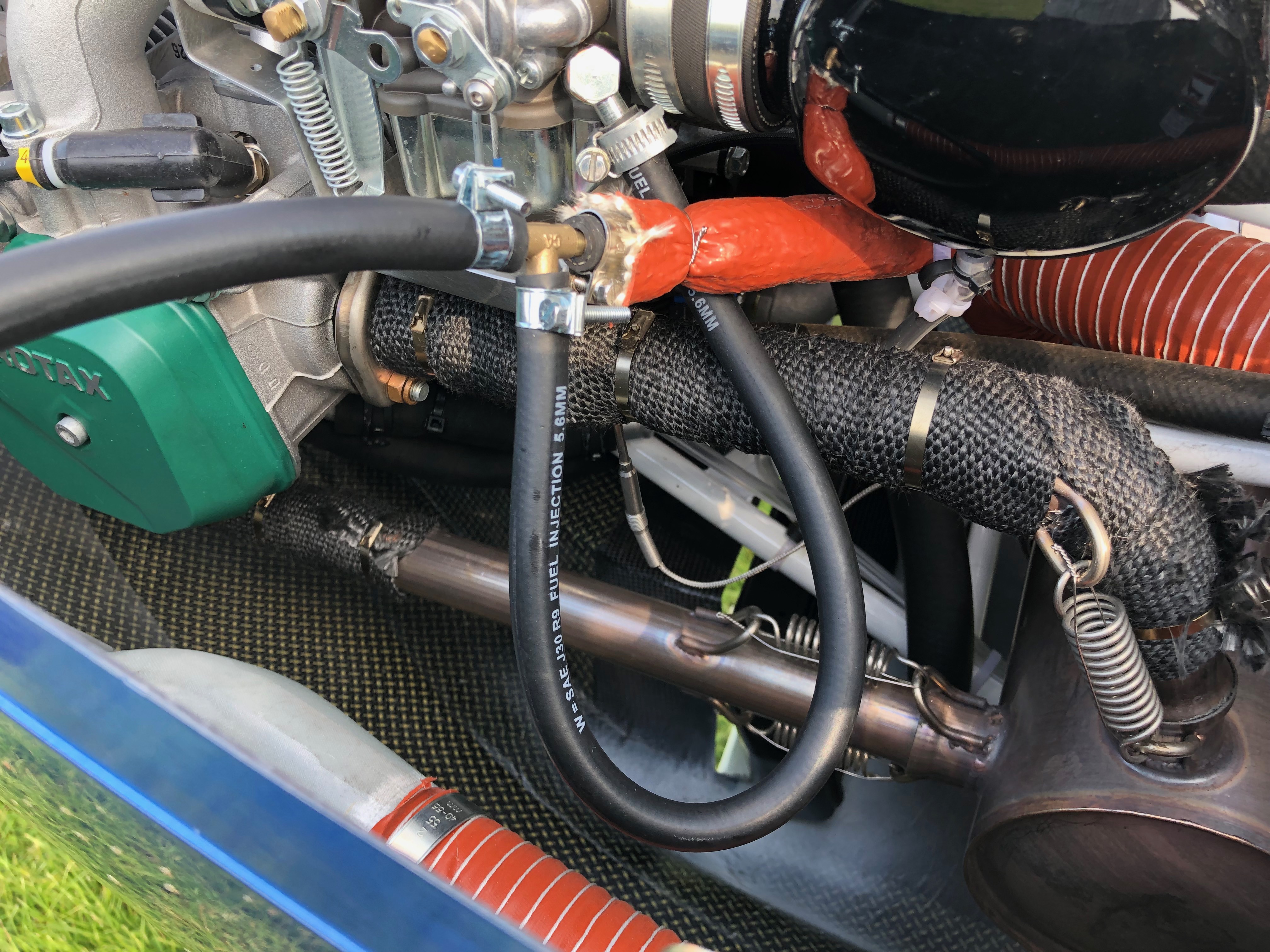
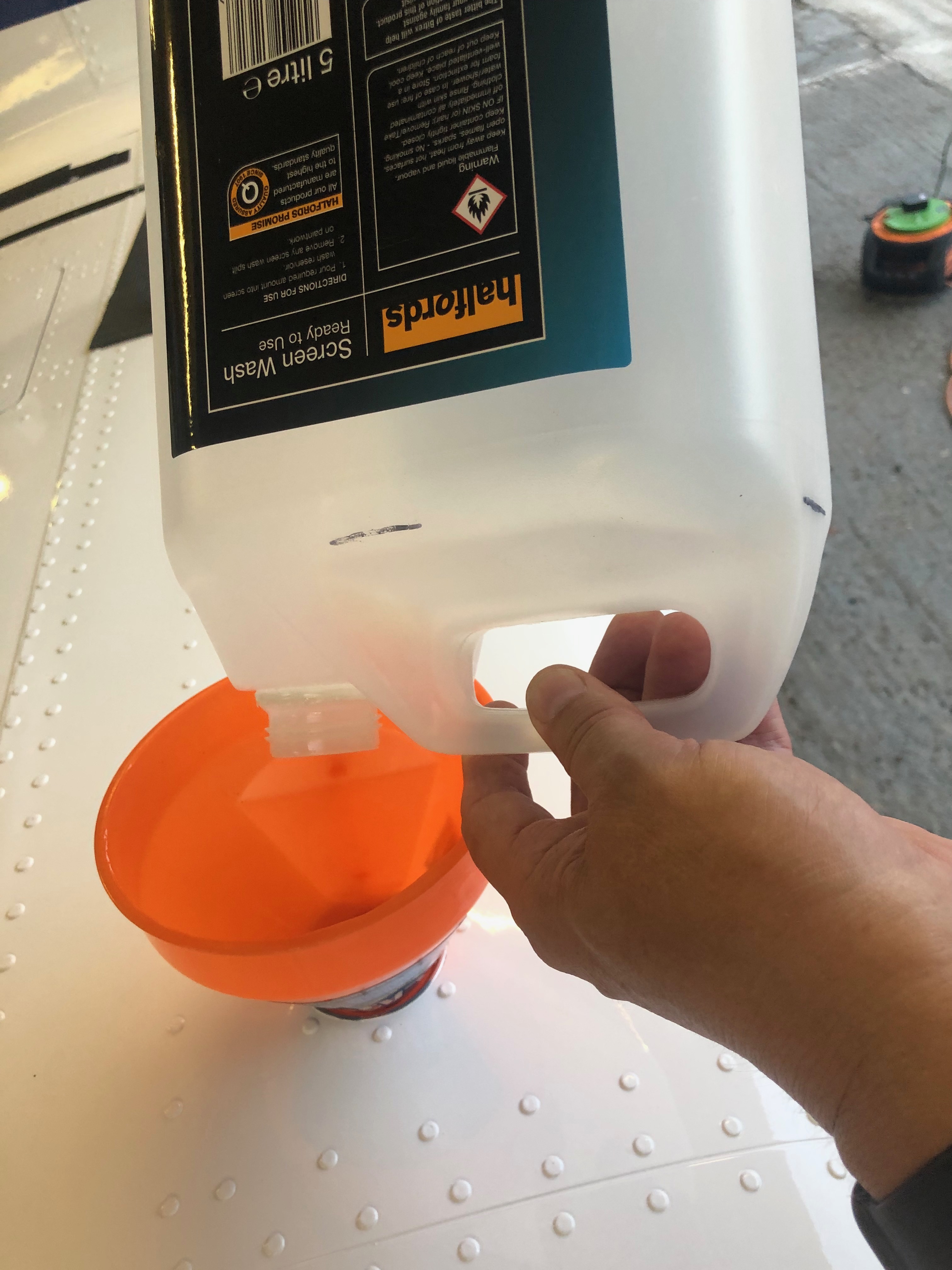
Once configured a check needs to be carried out between measured and actual fuel flow. I removed one of the banjos from the carb and captured the flow in a measuring jug to carry this out. With no restriction the electric fuel pump delivered 66 litres per minute and when restricted to give 3 psi within the fuel system the flow rate was 44 litres per minute. This is significantly more than the 27 rpm that the engine needs at full throttle.

Testing throughout the RPM range was carried out switching between left and right tanks and using the engine pump and engine and electric pumps options to ensure there were no issues with fuel supply.
After the engine runs a thorough check of the installation was made to ensure there were no leaks or issues.
All’s fine so now for the paperwork for the LAA.
Worksheets covering the work carried out and a fuel flow check form needs to be completed. A suitable entry needs to be entered in the Airframe logbook signed by myself and a permit maintenance release needs to be signed off by and LAA inspector with the appropriate authority, in this case Ian Daniels.

Wednesday 4th March 2020 – Fuel Flow Transducer

Now the transducer is mounted the fuel lines are run from the 4-way connector to the unit and the output line is run to the ‘T’. At each stage of the installation the fuel line is purged with fuel to ensure no debris is present that could block the fuel flow to and from the unit. Once the fuel hose is connected and secured with pipe clips, fire resistant sleeving is added and secured into place with wire lock.
The 4-way and ‘T’ connectors can be positioned adjacent to each other allowing for a neater installation.
And the fuel lines are covered with fire and heat resistant sleeving and wire locked into position.
The finished installation with the fuel pressure switch just visible at the bottom of the photo.

So just enough time in the day to re-assemble everything before departing for Vienna leaving the wiring to the EMS and test runs for when I return. No rush to finish as the runway is still sopping wet at Maypole and there’s more rain to come!

Tuesday 3rd March 2020 – Fuel Flow Transducer

Due to Maypole’s runway and taxiways being waterlogged, it’s not been possible to fly since before Christmas. I decided to use the time to do some more work on the plane. I had originally made the decision not to fit a fuel flow transducer but after flying the aircraft a few times I realised that the addition of a transducer would help me understand how much fuel I’m using more accurately than I have been using a spreadsheet. It would also help me on some of the longer flights allowing me to balance fuel use against speed.

So on the 4th Feb I talked to the LAA and asked what was the best approach to carry out the mod. I didn’t want to start the mod only to wait ages for the approval to come through. They said that the best thing to do is send the paperwork in and await their approval as it could take a while to be approved. To my surprise I received an email from the LAA on Friday 28th to say that I could go ahead with the work.

First thing to do is make a bracket to mount the transducer on. I used a piece of aluminium angle which would be screwed to the firewall using M6 screws and thick rubber washers to absorb any vibration.
The transducer requires 1/4 NPT 27TPI fittings to connect to the fuel pipes. These are sealed with Loctite 577.
Part of me thought ‘if it ain’t broke don’t fix it’ but I think the work needed to fit the transducer will be worth it in the end. So it’s time to start removing parts…
With the parts removed I can try different positions to check the fuel fuel pipe runs and clearances. Despite quite a bit of space on the firewall there are very few places the transducer can be mounted as it has to be mounted with the wires at the top and with straight runs of fuel pipe each side to reduce any turbulence in the fuel flow as this may cause erratic readings.
The existing and proposed fuel feed schematic. Essentially the 3 way and 4 way connectors are swapped and the transducer is inserted in the line leading to the 2 carbs so only one transducer is required. Other installation options require two transducers, one on the feed and one on the return line but this is a much simpler method.
In the ‘as built’ scheme, the 4 way connector takes the fuel from the mechanical pump, splits to the carbs either side and the forth connection is restricted and returns any unused fuel to the left tank. In the new scheme the outlet of the transducer is fed into the 3 way connector which supplies the carbs. The 4 way will be inserted in the line between the mechanical pump and the transducer. The third spur will be connected to the fuel pressure sender and the forth, which is restricted, will be connected to the return line to the tank.
The mounted transducer with the fuel pipes connected but without the fire sleeving. Quite pleased with today’s progress but ran out of time so will hopefully finish the installation and wiring tomorrow and perhaps even carry out some test runs.

Friday 3rd January 2020 – Rotax Mandatory SB-912-073

Rotax issue Service Bulletins alerting owners of known issues or defects that need addressing. The first was to replace the carbruettor floats that have been found to be soaking up fuel and sinking. This could cause rough running or even engine failure. I changed these before the first flight to ensure my test pilot wasn’t at risk.

The latest one applies to my engine and relates to a circlip that holds the jet needle in place. The reason stated was ‘Due to deviations in the manufacturing process a partial fracture of the circlip may occur. This fracture might lead to a crack/ total fracture of the circlip which in consequence may lead to a malfunction of the carburettor. Possible effects might be rough engine running or an unusual engine operating behaviour.’ The replacement needed to be done within 25 hours of the notice issue date but in any event no later than 31st July 2020. Replacement circlips and the ‘O’ rings were supplied under warranty from CFS

As the engine is just coming up to 25 hours and with Maypole’s runway waterlogged it was an ideal time to carry out the change.

The circlips…
and ‘O’ rings supplied under warranty.
The first thing to do is to remove the carburettor tops which requires the choke spring and …
throttle and choke cables to be removed.
The two screws retaining the top are removed…
which allows the top, spring and …
…the slide to be removed.
The needle retaining screw is removed next but Loctite has been applied to the thread so it’s quite tight to remove. Luckily it unscrewed without too much force.
Once the retaining screw is removed the needle can be withdrawn the circlip removed and replaced making sure to note which of the 4 grooves it was located in first!
The ‘O’ ring that stops the needle moving in situ is recessed in the retaining screw and is also replaced.
The needle is reinserted and Loctite 243 is applied to the retaining screw.
The carburettor can now be reassembled…
and the choke and retaining springs reattached. The last thing to be done is to reconnect the throttle and choke cables.
The carburettor reassembled.

Overall the process was very straightforward. The first carb took 45 minutes to do but the second was much quicker at 30 minutes. The engine logbook has been updated and the engine will be test run to check for correct operation before the next flight.

Let’s hope there’s not too many more of these mandatory service bulletins affecting my engine!

Friday 25th October 2019 – Removing the Thermostat

Yesterday we received an instruction from Bristell UK to remove the coolant thermostat if you had fitted one. They state that two Rotax 912 ULS engines have had to have cylinder no. 1 replaced due to overheating and they claim that the thermostat caused. With no other information it seemed sensible to remove it although now I effectively have a €250 aluminium 90 degree connector. Quite frustrating.

The Silent Hectik thermostat. Very well made with a 80 deg C thermostat hosed within it.
To remove the stat required the casing to be heated with a hot air gun. That softened the Loctite holding the screws. Once removed a little bit of Wellseal is used to help seal the ‘O’ ring, Loctite applied to the screws and then reassembled. As I was going to use the housing as an expensive 90 degree connector I thought it was a good idea to mark the casing with “Thermostat Removed’.
Reinstalled and ready for the system to be refilled with coolant. Job done in just over an hour.

Thursday 15th August 2019 – The Fuel Flow Test

One of the jobs that I’ve not looked forward to is the fuel flow test. Not because it’s difficult or complicated but more that it seems dangerous. It involves taking a feed off of the carb line and running a long pipe away from the engine and prop. Several timed measurements take place using the electric pump on it’s own with the engine stopped, one with the engine running at full bore using just the mechanical pump and one with the mechanical and electric pumps working together. The aircraft has to be choked and Ian offered to do the work outside the cockpit. We used radios to signal the start and stop of each engine run.

The run off from the carb fuel line using a ‘Tee’
Ian hiding under the wing carrying out the fuel & time measurements. For the electric pump only run the amount that needs to flow is 125% of the maximum litres per hour for the Rotax. For the measurements where the engine is running at full bore, 27 litres will be used by the engine before any excess is collected so the excess should be 25% of the maximum per hour fuel amount so were expecting 6.75 litres as a minimum.
The T&Ps at full chat look ok and the fuel flow results are far in excess of what’s required. Poor Ian need a new set of ears now though!

Friday 9th August 2019 – Adjusting the Prop

With the aircraft substantially complete and awaiting Ian to return to carry out some sign-offs I’m finishing off some smaller jobs that I can do whilst I wait. This includes adding a few more placards and labels, some more taxiing to check nose wheel alignment and brake operation, a couple of engine runs to check its operation and allow me to run to maximum RPM so I can set the fine pitch stop on the Airmaster prop. I’ve also purchased a battery charger for for the Shorai Lithium Iron Phosphate battery that I’ve fitted that balances the cells and ensures a better operation. The upside to this is that it comes with a special lead that fits to the centre port of the battery and not the usual batter terminal. This allows it to be permanently fitted.

The Bristell kit comes with G405 stick grips but I wanted to put the autopilot disconnect and autopilot level buttons on the grip. so I have installed G407 grips instead. It comes with a variety of labels to identify the button function.
The Rotax 912 ULS can run on a variety of fuels but unless you placard them a refuelled may not fill with the option you request. I got the MOGAS sticker from the LAA and Chris Knight from Maypole had a few of the AVGAS UL91 and 100LL stickers.
As the special battery charge lead plugs into the centre port I had to move the battery slightly off centre by moving the packing but was an easier option than re-siting the battery retaining strap.
I’ve run the charge lead to the oil inspection hatch which will allow me to charge the battery or keep it in maintenance mode without taking the top engine cowl off. Quite a neat solution.
One of the things I needed to do was set the Airmaster fine pitch. This involves putting the prop in manual mode and throttling up to just under maximum RPM at 5700. Once this is done then the engine can be shut down and the adjustment made.
Took this just to record some sensor readings at max RPM. Oil temp is a little high which may be because I’ve been stationary whilst running the engine at high RPM. I will be checking that…
Now I’ve set the prop pitch so the engine peaks at 5700 I can set the fine pitch cam. The pitch motor cover is removed to reveal the microswitches and cam adjusters…
The locking nut is undone and the cam adjuster is turned until you hear the microswitch operate and that’s it – very simple.
All that’s required is to reassemble the pitch motor cover and now the fine pitch has been set I can wire lock the screws to make sure that it doesn’t loosen whilst in operation.

I must admit the more I work with the Airmaster prop the more I’m impressed with the quality and engineering. It’s brilliantly simple and well worth the extra I paid. It will be good to see what the performance when it finally flies but from what I’ve seen so far has impressed me. I can virtually guarantee maximum RPM for takeoff and tune the prop for climb and cruise. The fact that it has a 2000 hour TBO to match the Rotax and it’s user maintainable at 100 hours intervals means it will be very cost effective over the coming years.

Friday 26th July 2019

Music: My Rotax bursting into life on the first turn.

Video of first engine start: https://1drv.ms/v/s!Au02Zz1cs6-RgbAhlIeJQiX5mrKNxA

With only a few things left to do one of them is to set the control surface deflections. On the face of it, it’s an easy job but it requires a differential movement from fully up to fully down. Due to that specification there’s more than one place to adjust. It requires a bit of juggling to get it right and in the heat of Thursday it wasn’t the day to do it.

One of the adjustment points in in the rear of the aircraft with a very small inspection panel to undo nuts and make the adjustment. It was very tricky and time-consuming but got there in the end. I used an iPhone inbuilt app for the level that was then checked by Ian who has a digital protractor. Amazingly the iPhone reading match Ian’s readings +30 deg -15 deg.
Ian came round to ask if I wanted to run the engine today as he’s away Monday and Tuesday. With the temperatures very much lower today it seemed a good idea so we got on with checking everything was ok before taking it out of the workshop.
The workshop ceiling was far too low to fit the canopy so needed to do it once it was out. It took a lot of jiggling to get it out of the workshop and now it’s out it won’t be going back in!
Out on the grass away from all the stones and Pete Sharpe recording the event on my iPhone it’s time to do a final check before the first start. The electric fuel pump was switched on to check for leaks from the fuel system, all seems ok.
First time in the cockpit for real so another good check to make sure every thing is working as expected. Ian is standing by just in case anything goes wrong with a radio and fire extinguisher!
Canopy down, calling “CLEAR PROP” as I turn the ignition key and my baby burst into life on the very first turn – I can only shake my head in disbelief – Amazing!
Watching the Ts&Ps as the engine is running Ian does a walk round to check for any obvious problems but there aren’t any. It’s running as sweet as a nut.
After being told to smile I look up as one happy chappy…
Ian prompted me to taxy the aircraft to spread the noise about a bit so I did a few runs up and down the runway checking brakes, steering, instruments, pitot system and then power checks. All very good apart from the flys on the firewall. Ian carried out a further check once the engine had stopped but all was ok and there were no problems.
A very empty workshop. It seemed big enough when I first started but as time went on it proved to be too small to house the aircraft on a permanent basis.
So this is where G-MLSY will be for the weekend before being moved to its new position in the main hanger.

Tuesday 23rd July 2019

Music: Easy 90’s

Well the best laid plans as they say… however with the weight and balance carried out yesterday meant my downfall today. Everything needed to be on the aircraft for it to be weighed however I forgot to ask Ian and Pete to help me take the canopy off. So I arrived to realise that I couldn’t do any of the things I had planned for today as I couldn’t get into the cockpit 😦 Usually people come and go during the day but no one turned up until around 3! So a very short day today.

Up first was the calibration of the fuel tank sensors. This took longer than it should have done as I didn’t finish the process quite right on the first pass so needed to drain the tank and start again.

The calibration screen…
I used a screen wash container that I had filled to the 5 litre mark and then filled that for each calibration point. The process was quite straightforward. Press start, pour in 5 litres of fuel, press ‘Add’ and repeat 12 times on the last fill press ‘Full’ except on the last fill you need to press ‘Add’ then press ‘Full’ Silly me got that wrong so…
I had to drain out the tanks and start again! Eventually I finished it. The port wing will have to wait for tomorrow.

Monday 22nd July 2019

Music: None today – Concentrating!!

Weighing day today! Pete Thomas a good friend from the London Gliding Club offered to come down to weigh G-MLSY and today’s the day!

Everything needs to be fitted for the weighing. So the spinner is first and the canopy is lifted on but is won’t be secured yet.
Ian as my LAA inspector is overseeing the process to make sure it’s down to the LAA standard.
Pete starts the process of laying out the pressure pads.
The aircraft has to be exactly level for this so a spirit level is placed across the cockpit and on the cockpit edge and adjustments are made as appropriate.
With the aircraft sitting on the pads and levelled both lat and lon weighing can begin.
The datum marks have to be calculated so a plumb line is dropped from the reference points and a position marked on the floor. These marks will be used later in the calculations.
Pete in action marking the front datum.
All done now but a quick pic with everything on before we start to take it off again for the final set of inspections.
I’ve done the wing and starboard side registrations but didn’t get chance to go the port side. It’s amazing how quick I did this side compared with the other. At least twice as quick no I know what I’m doing!
Now a pick from the left. Looks quite nice.
The end of another day. Please with the process so far and not long now to the first engine runs and flight.