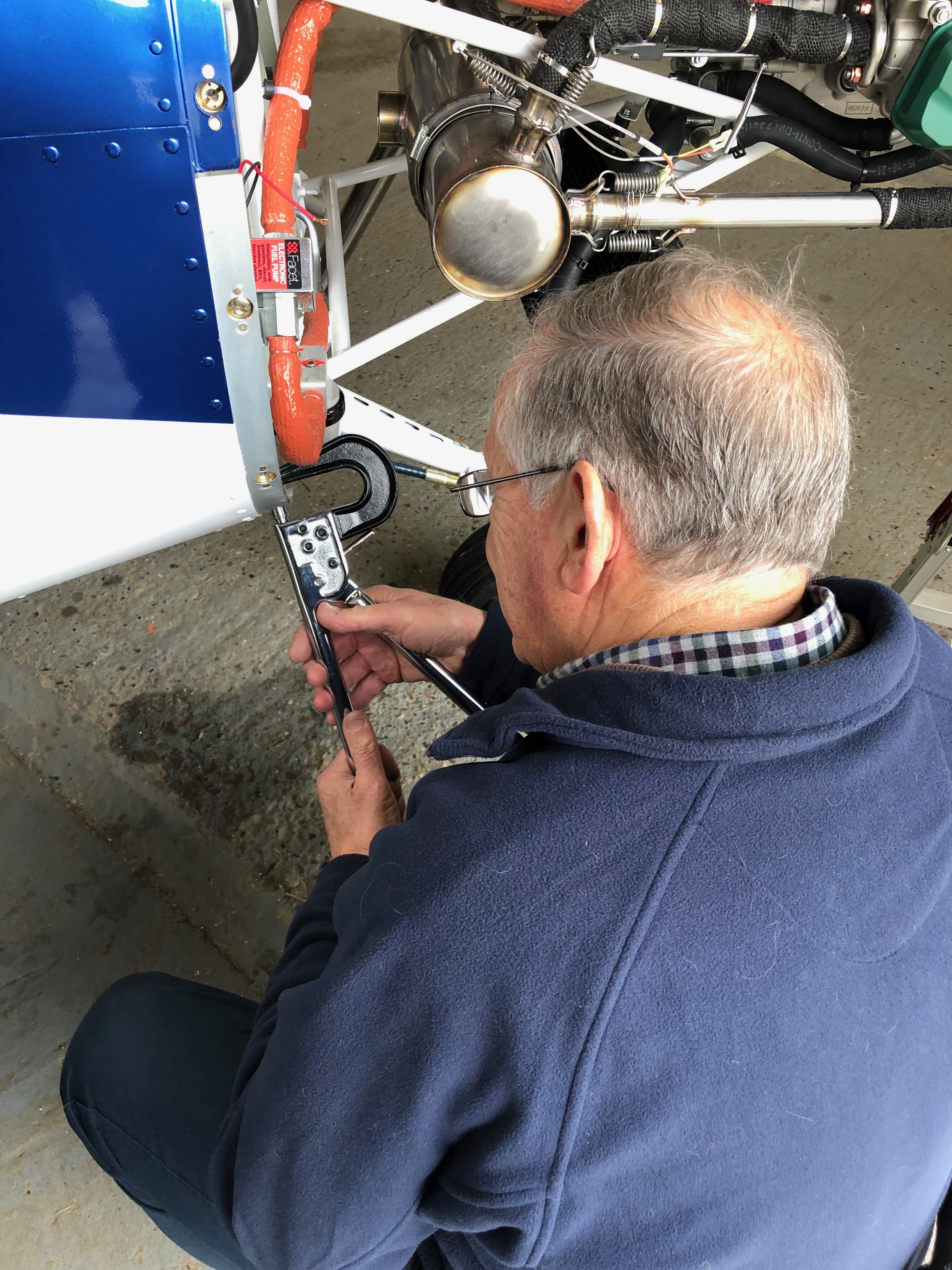
When the aircraft was painted the cowls fasteners were fitted however they weren’t fitted very well. I decided to remove all of them and start again. Having spoken to Ian Daniels my LAA inspector he agreed and said that he would refit them with solid rivets.
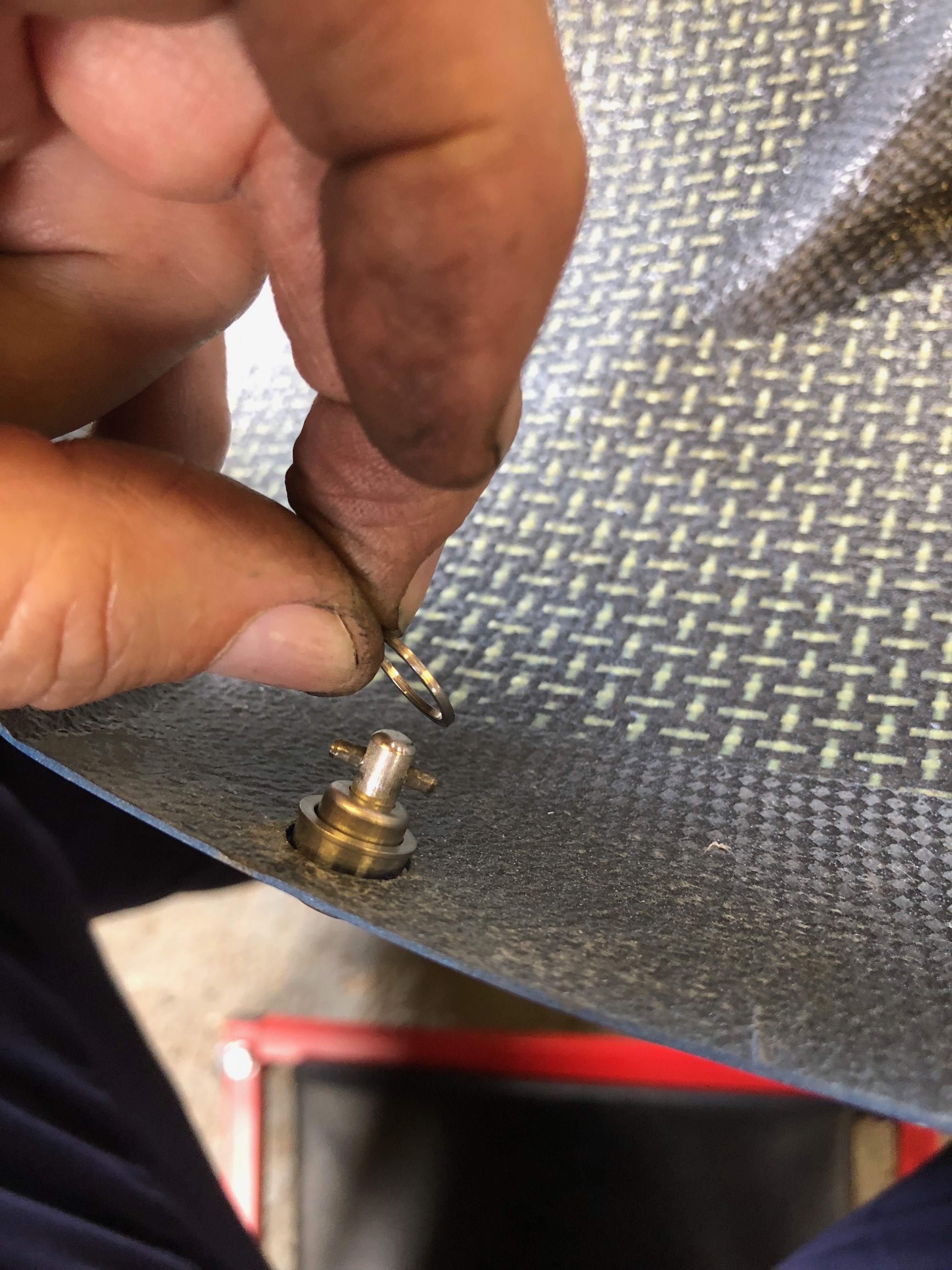
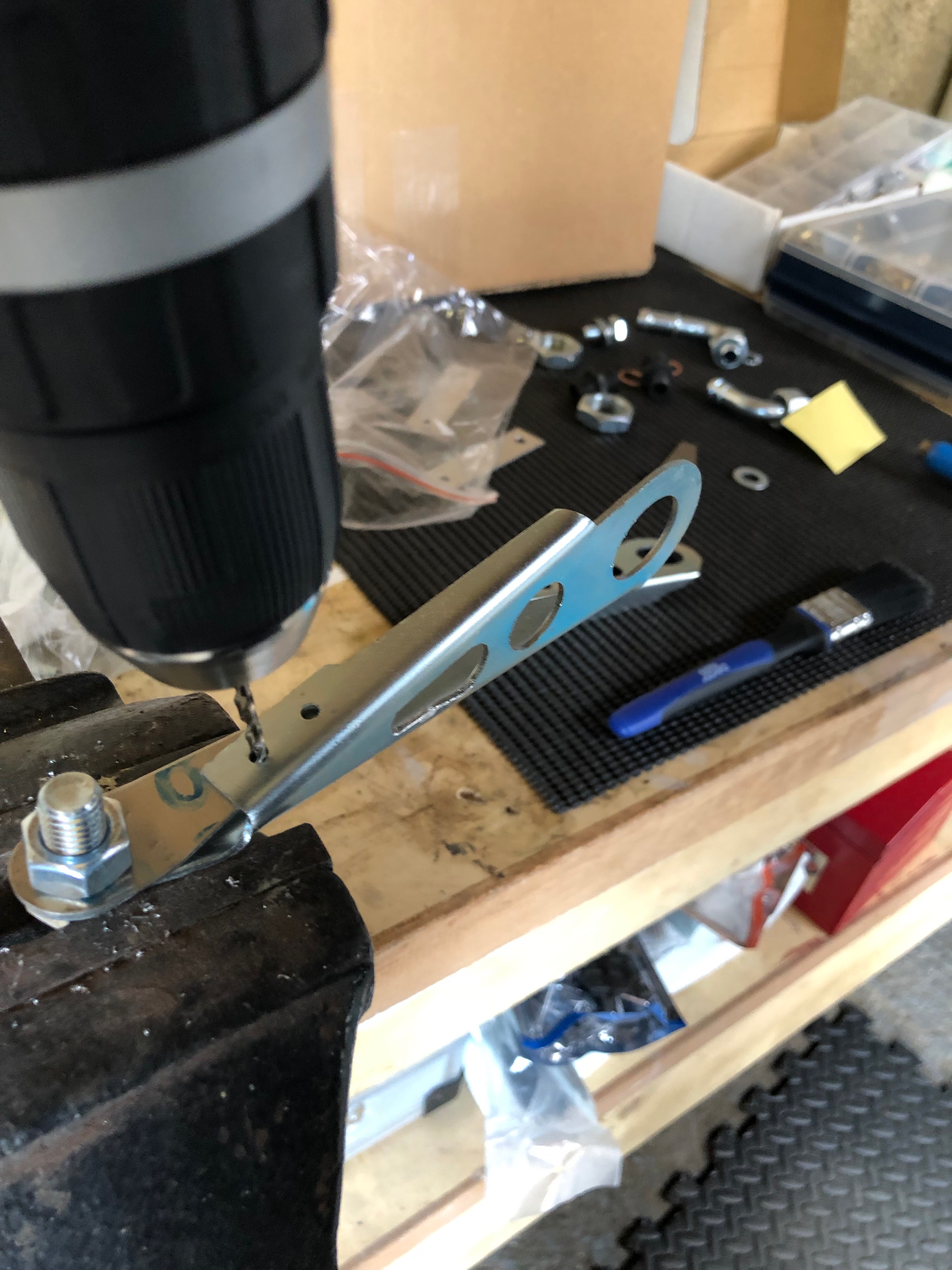
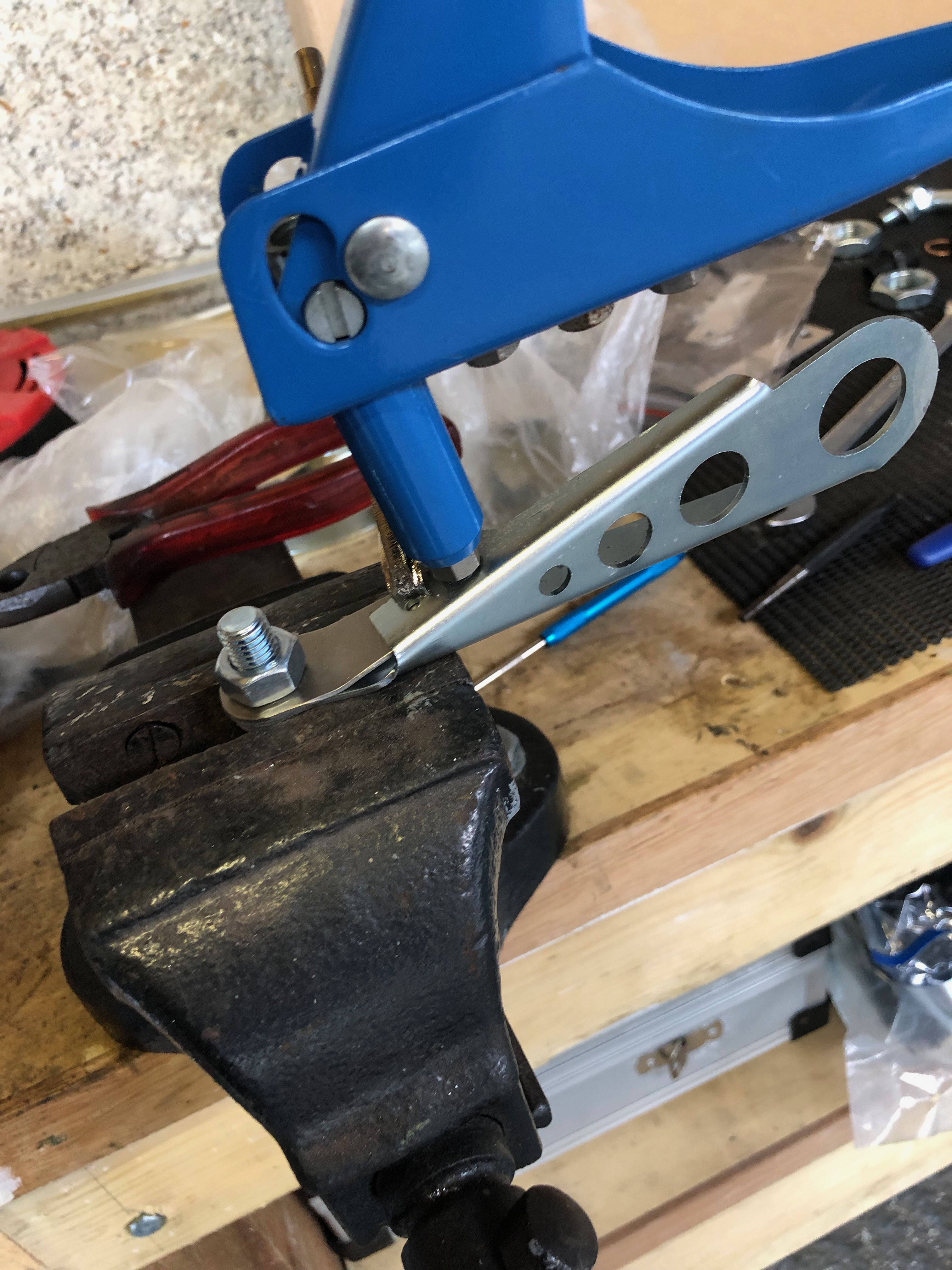
First thing was to use a parallel drift to punch out the hardened pin from the rivet.
Then the head needs to be removed with a large drill bit. Need to be very careful here as there is a chance that the hole could be enlarged which would cause problems when re riveting.
The fitting is removed and the old rivets are punched out.
Ian doesn’t lend his rivet squeezer out so did the job for me – saved me a job.
The result is much better, they are completely flush now and won’t rub on the underside of the cowling.
Ian in action squeezing one of many solid rivets.
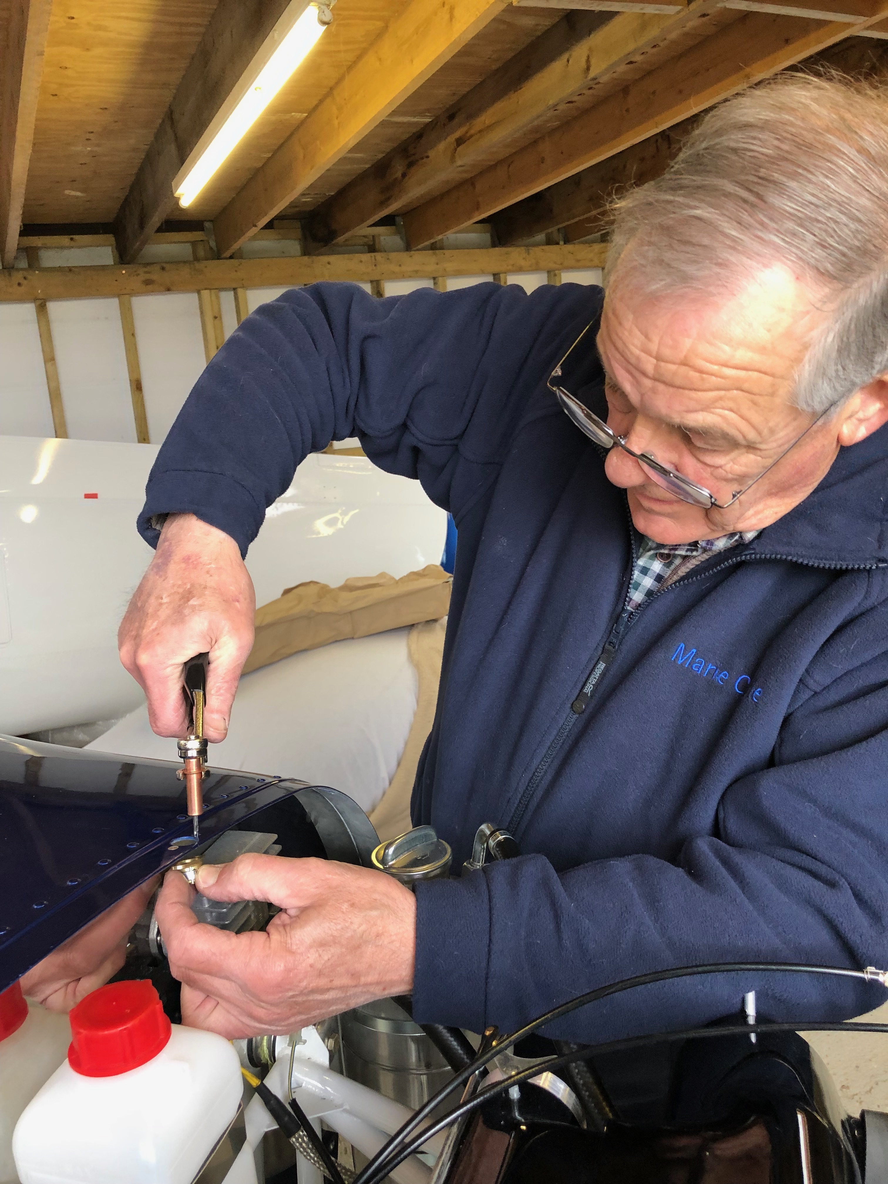
The cowl is secured by quick twist screws which are held in position by spring washers. These are installed in the top cowl.
A little fiddly to install when you first start out but they are quite easy to install with the help of a small screwdriver.
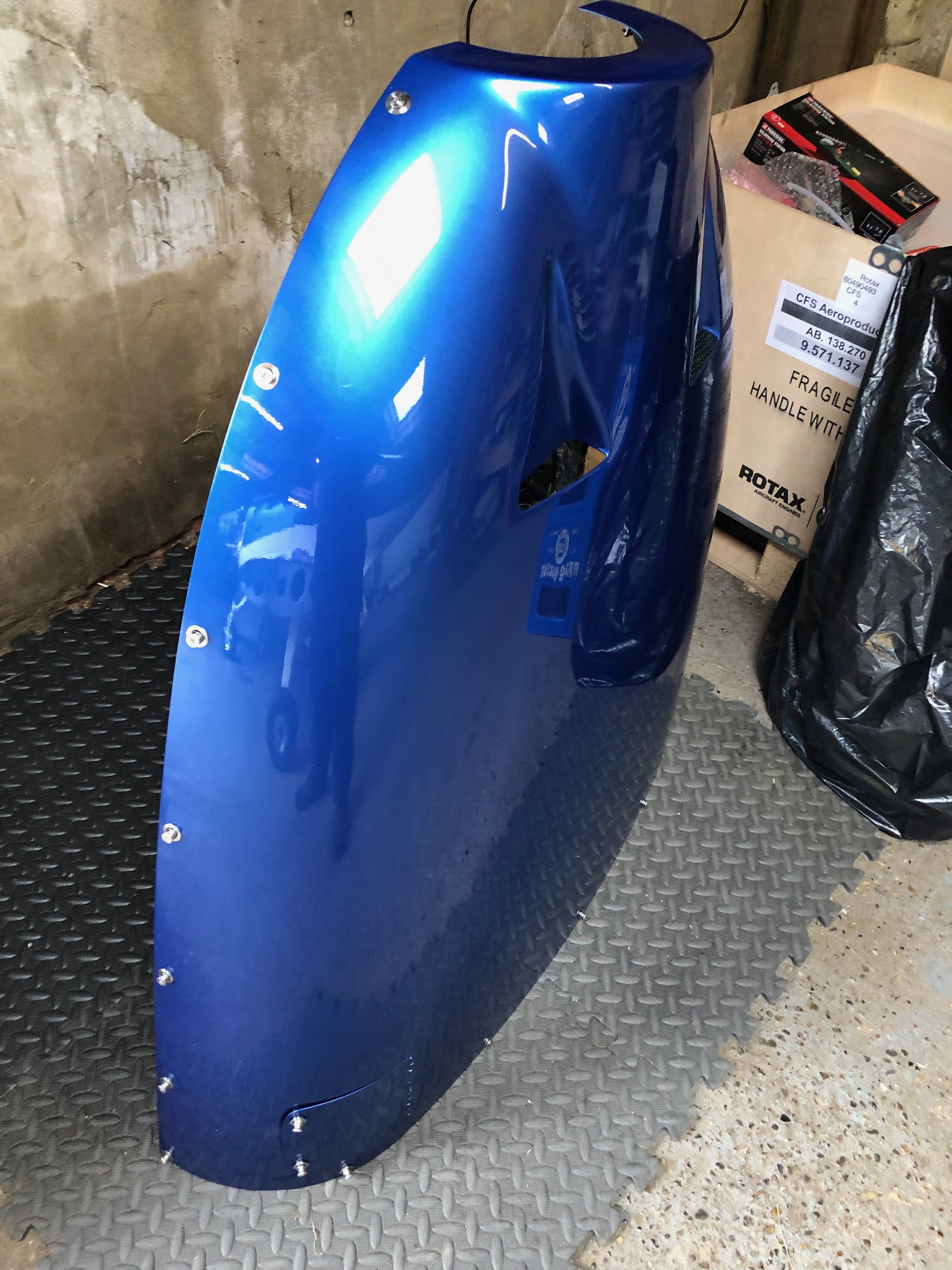
The top cowl with the quick twist screws in place including the ones for the oil inspection cover.
The bottom cowl quick release fasteners are fitted, the ill fitting fasteners will be removed, re countersunk and the fitting secure with solid rivets as described before.
One final job was to replace the exhaust system spring wire locking I had applied as I wasn’t quite happy with the way I had done it. The wire should prevent debris being dropped from the plane and create FOD should the spring fail in service.
Now I’ve received the water thermostat I can finish the water system, install the EGT sensors and complete the exhaust system.
Thermostat, hoses & clips for install.
The thermostat is fitted behind the expansion tank.
The hoses are attached…
and the radiator bottom support bracket is installed…
Once the radiator is fully installed I can check the cowls fit properly.
As you can see there is some trimming that needs to be carried out to make sure the cowl doesn’t foul the radiator.
Looks ok from the front.
The exhaust seems to clear the cowl however another check will be made before final assembly. The gascolator is located on the opposite side to the exhaust pipe and requires a hole to be drilled which will enable fuel checks to be carried out before flight.
The installed thermostat with just a ‘stand off’ to be fitted to make sure it doesn’t rub against the adjacent engine mount.
Now the cowl fitting has proven All the clips are fitted – job done.
I purchased a Kavlico EMS kit so the EGT sensors need to be installed.
A 3.2mm hole needs to be drilled in the rear exhaust downpipes 4″ from the flange.
Once the hole is drilled and sensor fitted it is held in place with the supplied, modified jubilee clip. The sensor has a ‘collar’ that ensures that the hole is sealed.
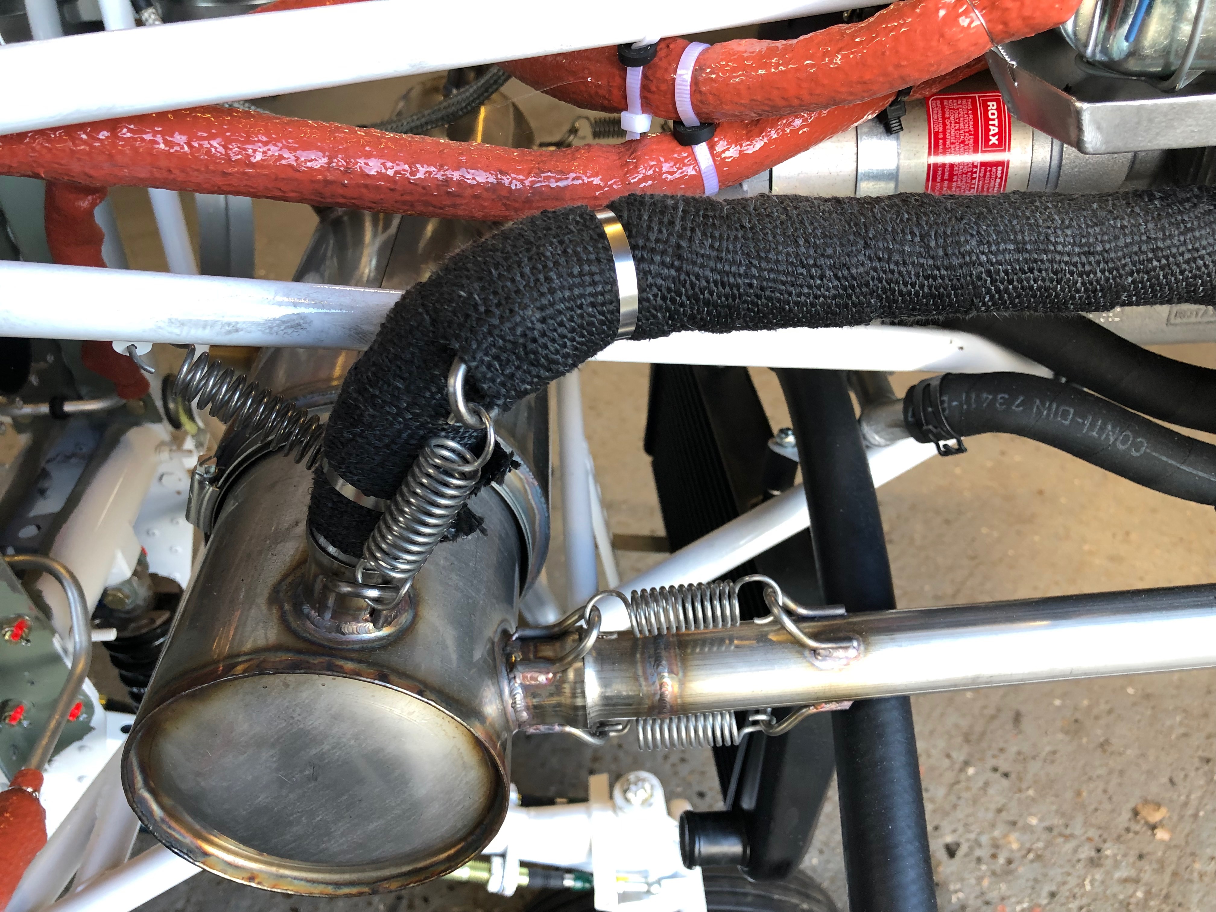
The downpipes are re-fitted and re-wrapped, securing in place with stainless steel ties.
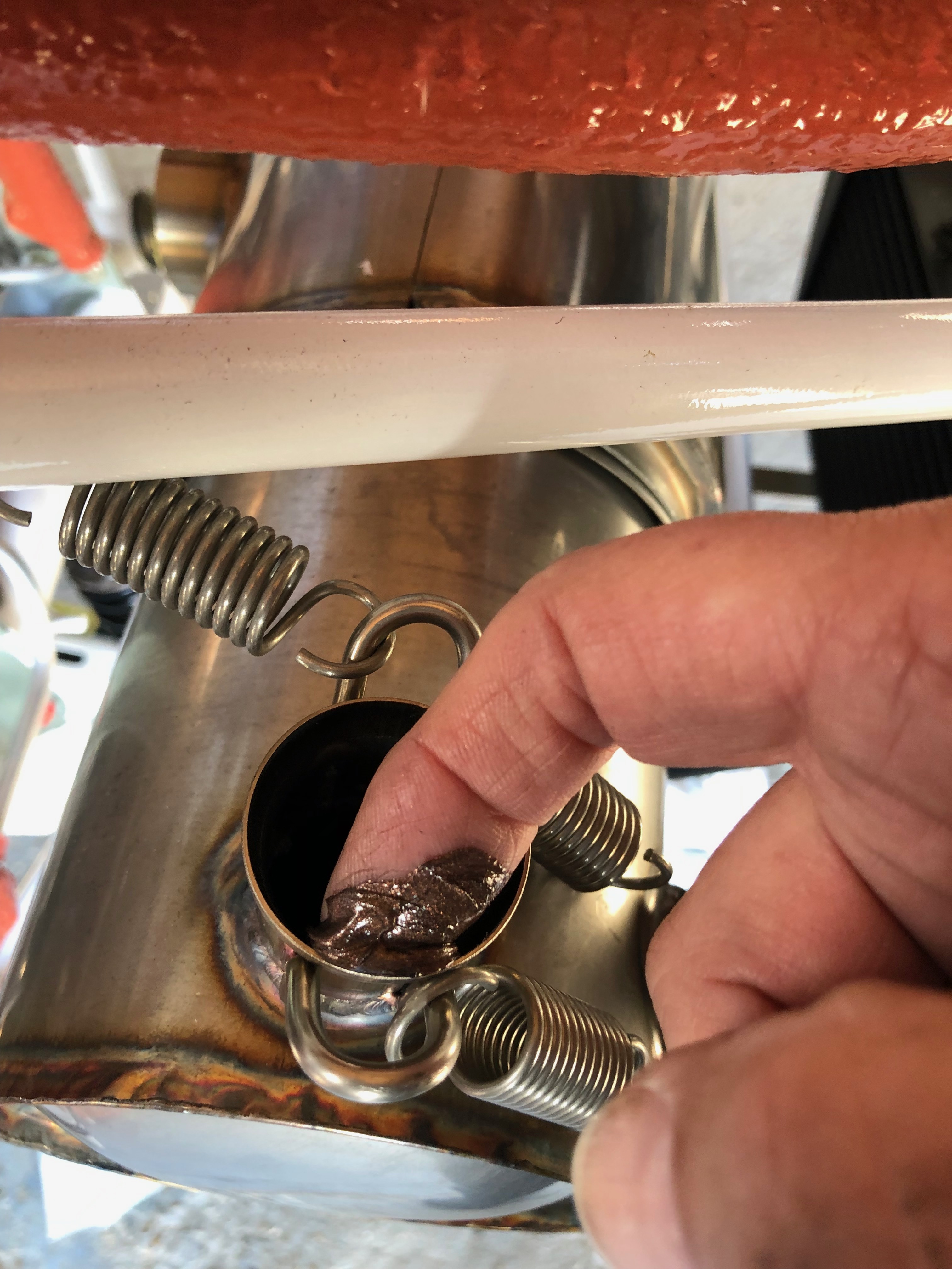
To ensure the springs don’t fall and cause a runway hazard if they fail in service they are wire locked. Tomorrow I will fill the centres of the springs with heat resistant silicone which reduces any resonance from the springs.
A few smaller jobs, including exhaust wrapping, sensor fitting and cable oiling ahead of fitting the water thermostat that I finally received today.
The landing lights come with a couple of spade connectors that need to be crimped on…
and then slipped into the connector block. I’ll need to do the same thing when I come to install the LEDs into the wing.
The MAP sensor is fitted to the firewall in a suitable position making sure that the plug don’t foul one another.
The space between the water bottle and regulator seems to work well.
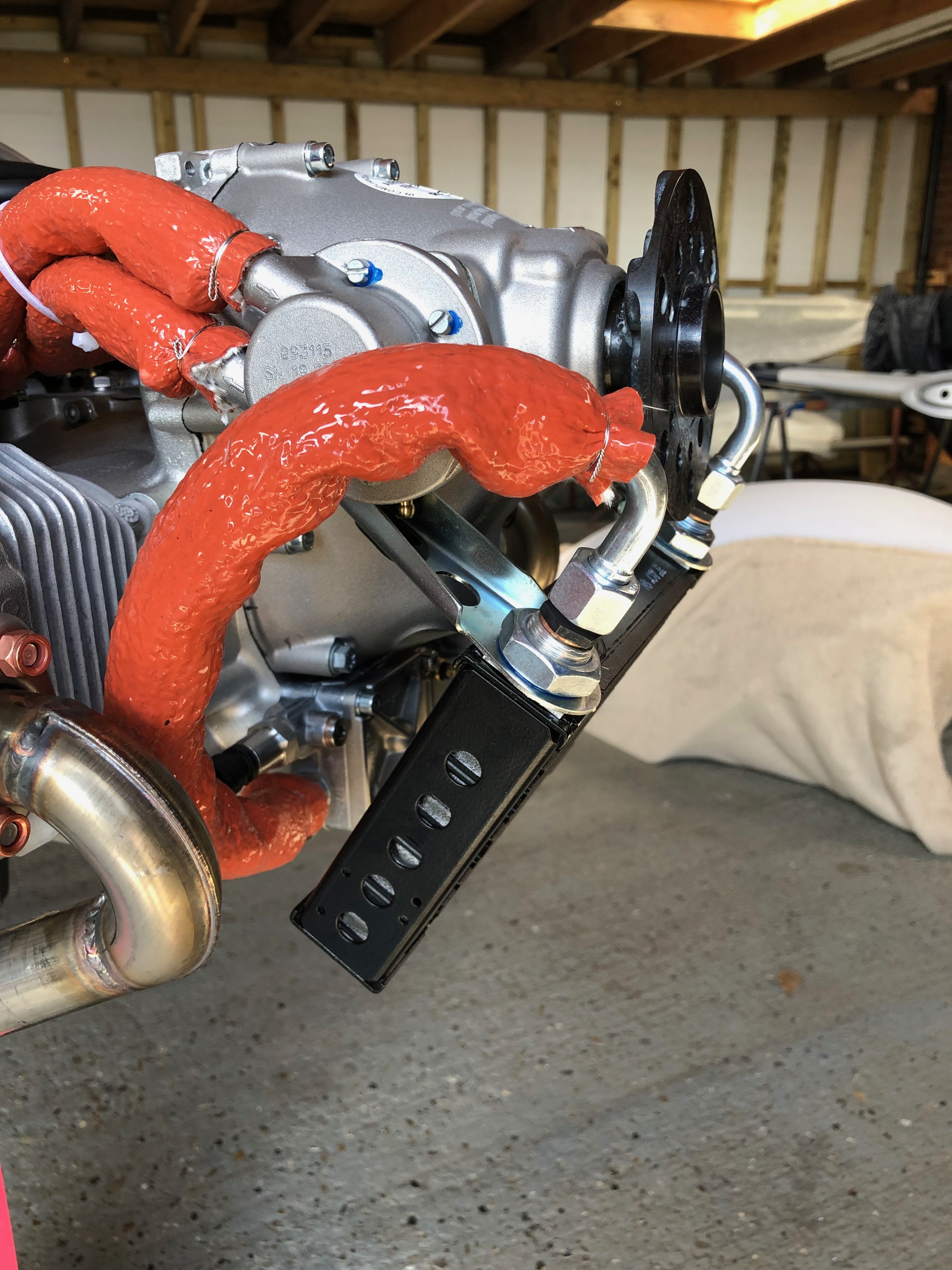
The front exhaust pipes covered in exhaust wrap and secured in place with stainless steel ties.
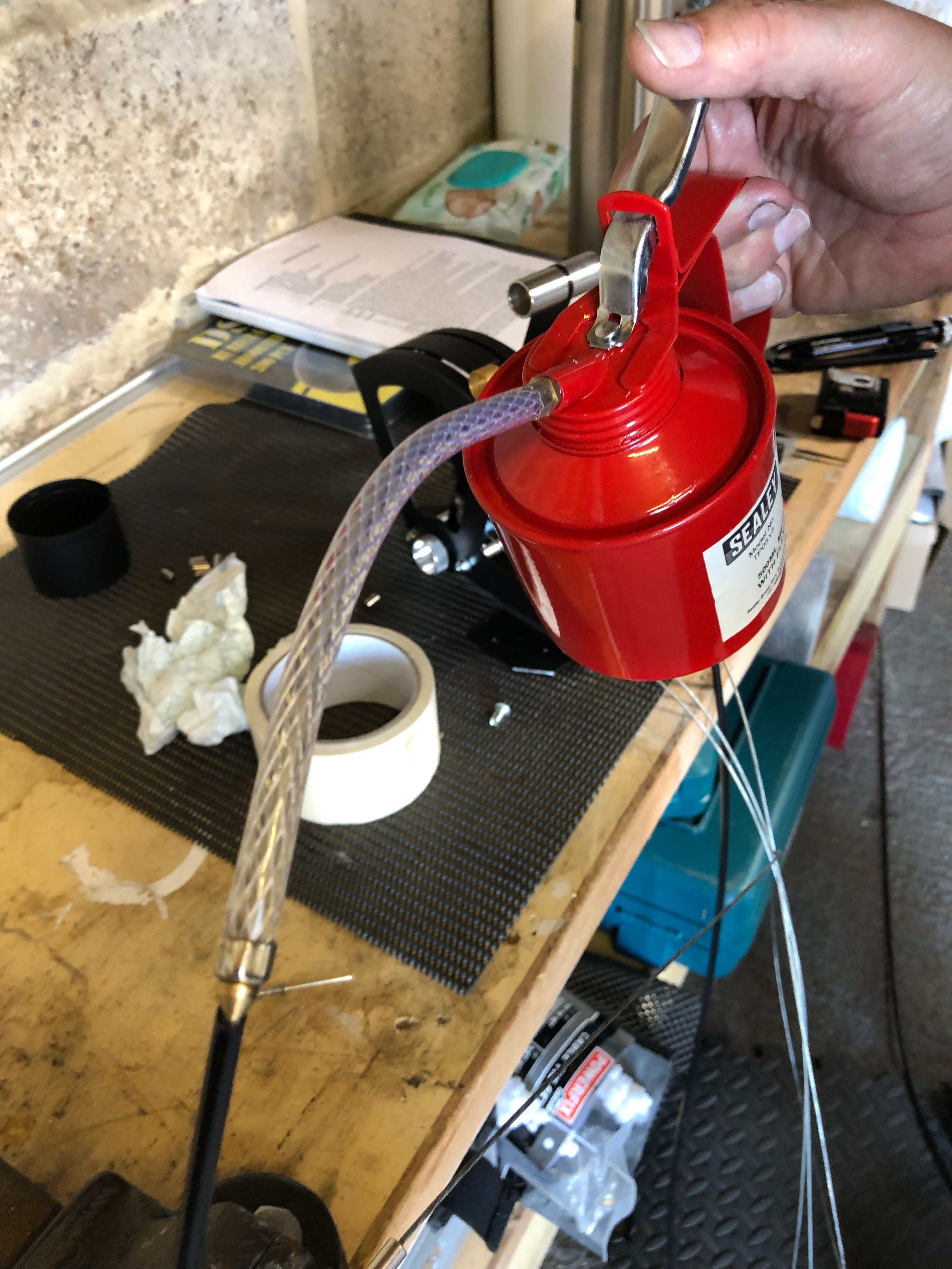
There’s several cables that need to be installed later in the build. Unlike the throttle cables these aren’t lined so require some lubrication.
Received at last! Good ol’ Parcel Force have had this since the 5th March but never left a card. It’s lucky I asked for an update on delivery from Silent Hektik otherwise I’d still be waiting. This is the 3rd time Parcel Force have completely screwed up on a delivery to me – I will never use them again!
Today was dedicated to completing the brake installation and starting on the exhaust wrap.
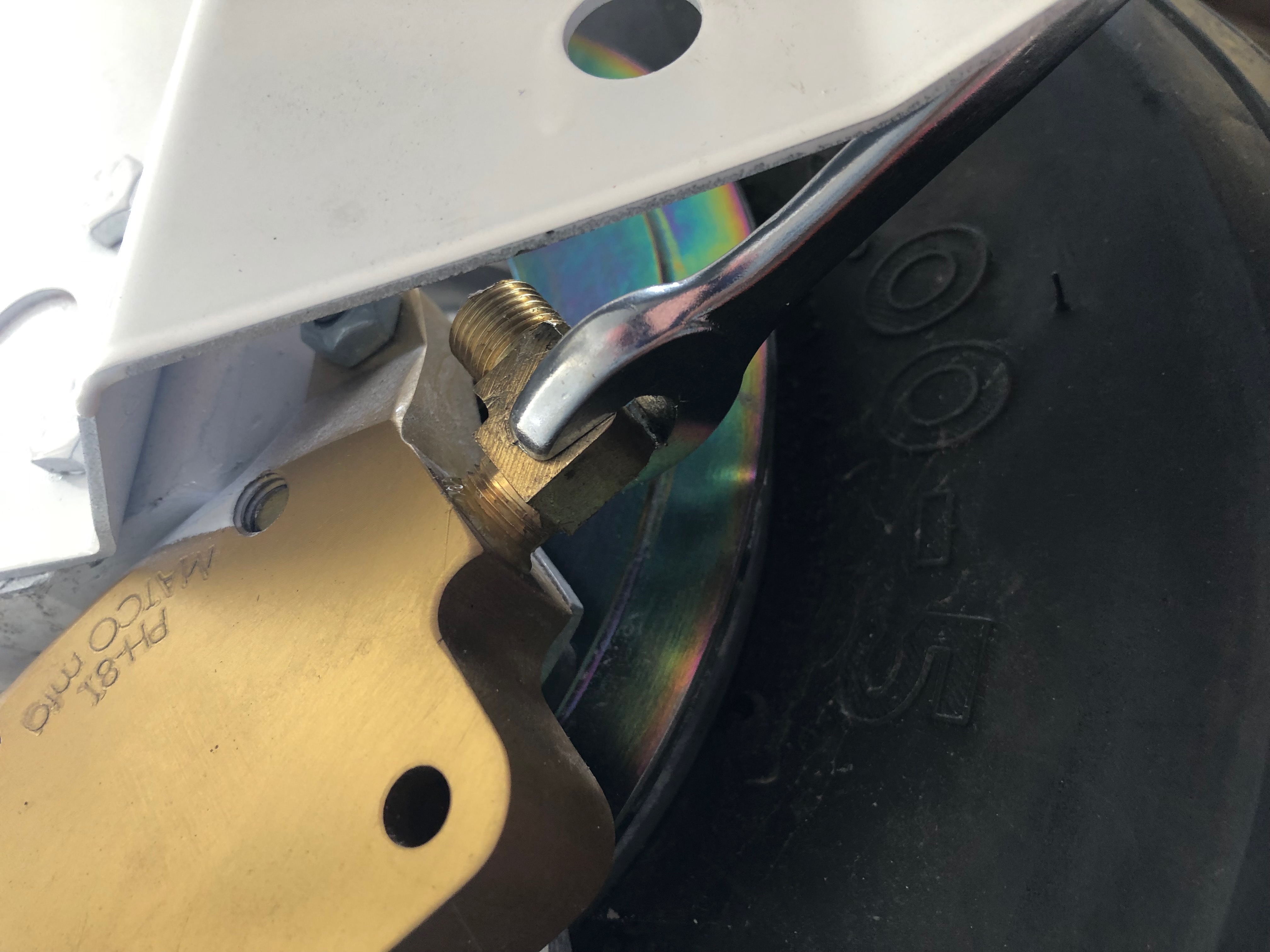
First up is to add Loctite 577 to the last two hydraulic elbows and fit them to the brake callipers.
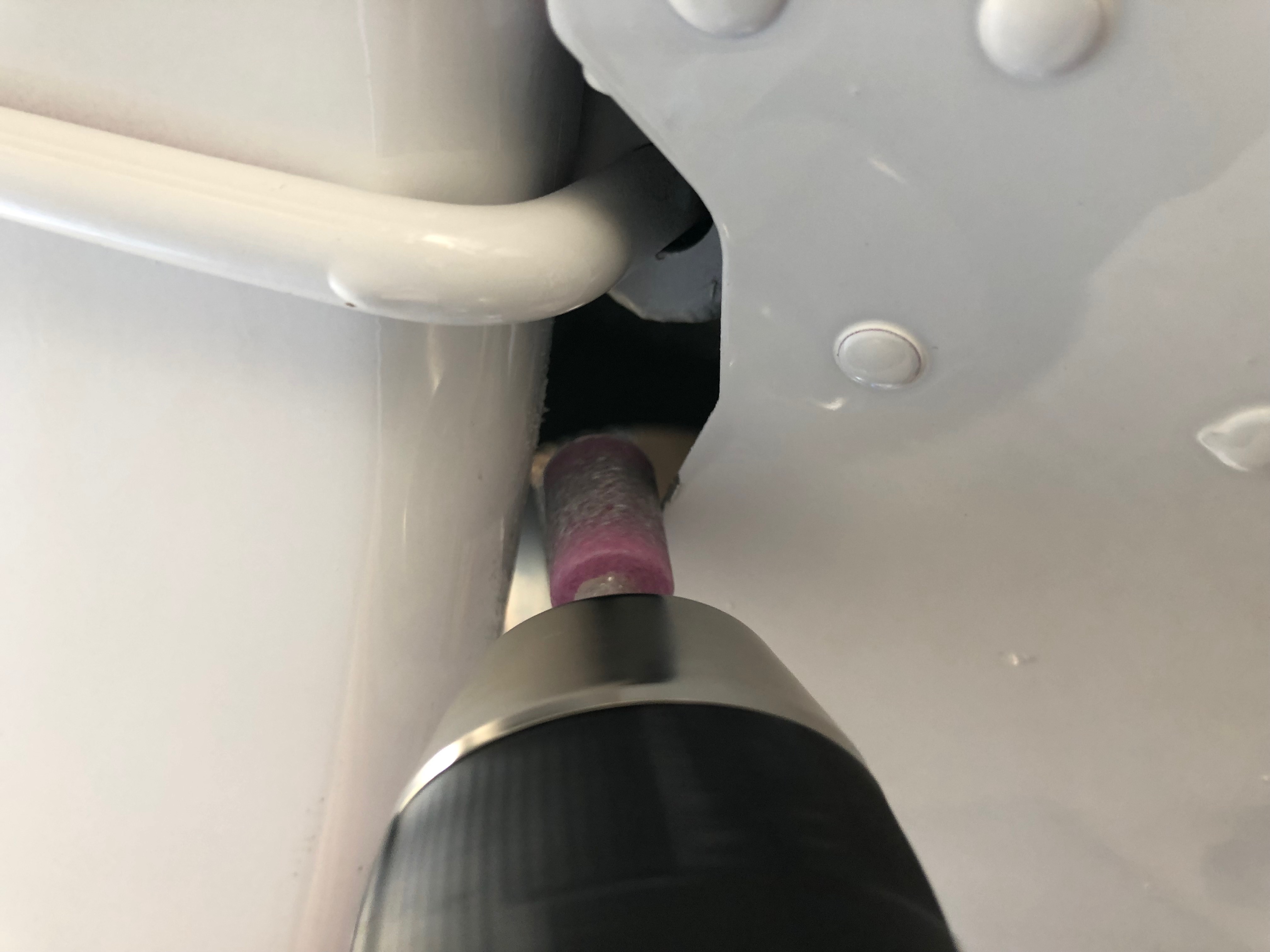
I thought it would be a good idea to cover the spiral wrap with some heat shrink tubing to protect the hydraulic pipes as it emerges from the fuselage and runs down the first part of the landing gear leg.
A slight change to the opening needed to be made to accommodate the extra width of the covered pipe.
The cover is slid over the pipe and secured in place with a tie wrap.
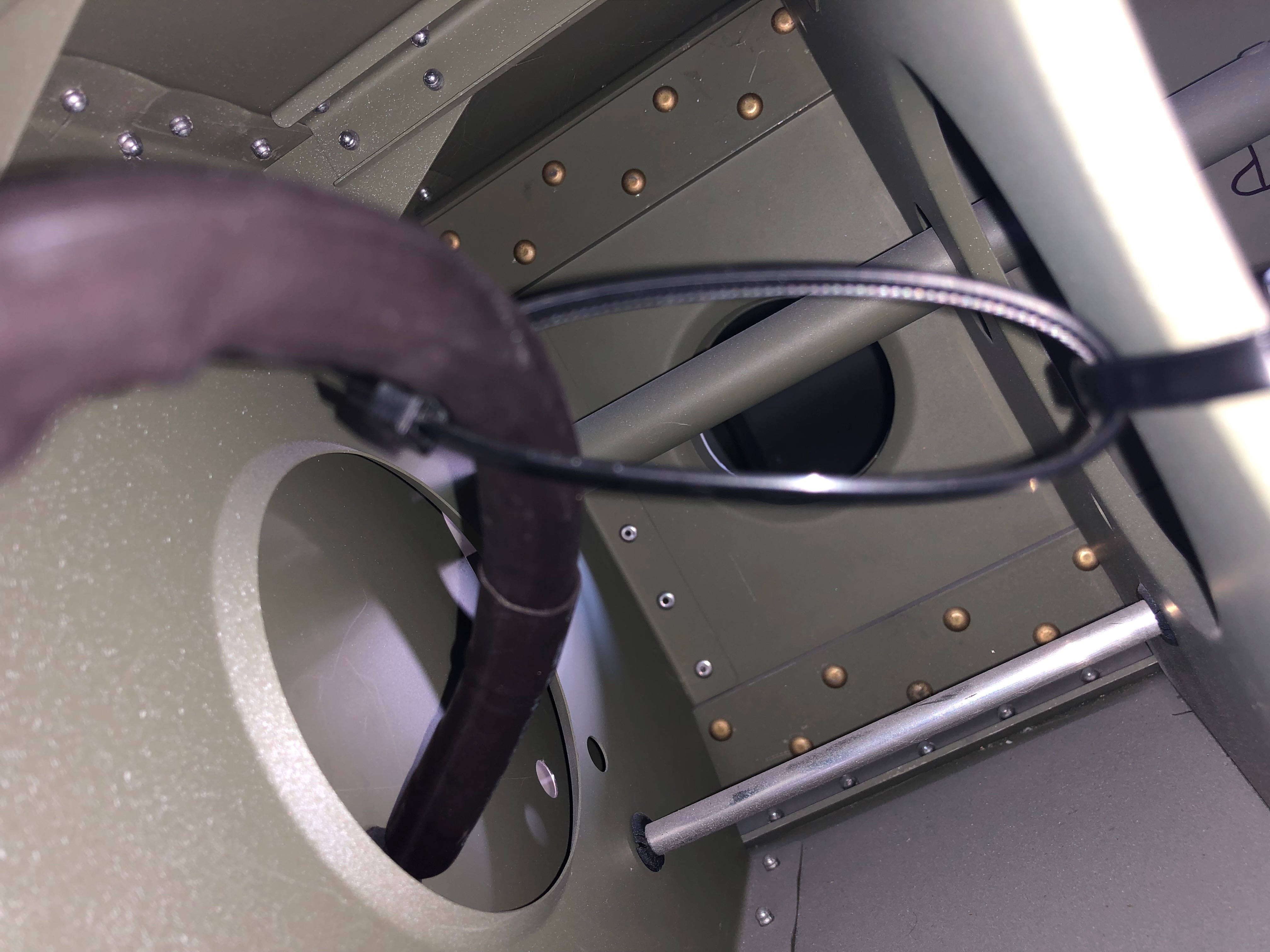
The pipe will be subject to movement when taking off and landing so the pipe is cut long to provide a loop to accommodate the movement.
The pipe run from the the master cylinder fitting to the park brake unit looked to be under stress so I removed it, cleaned it up and refitted using a different angle which allowed the pipe to ‘flow’ better.
Before tightening the compression fittings a metal anti-crush ferrule is inserted.
The pipe run runs over a ‘sharp’ edge so I added some protection to avoid chaffing.
The pipe is held lightly in place with some cable ties.
Took much longer than I expected but the brake system is complete – at last!
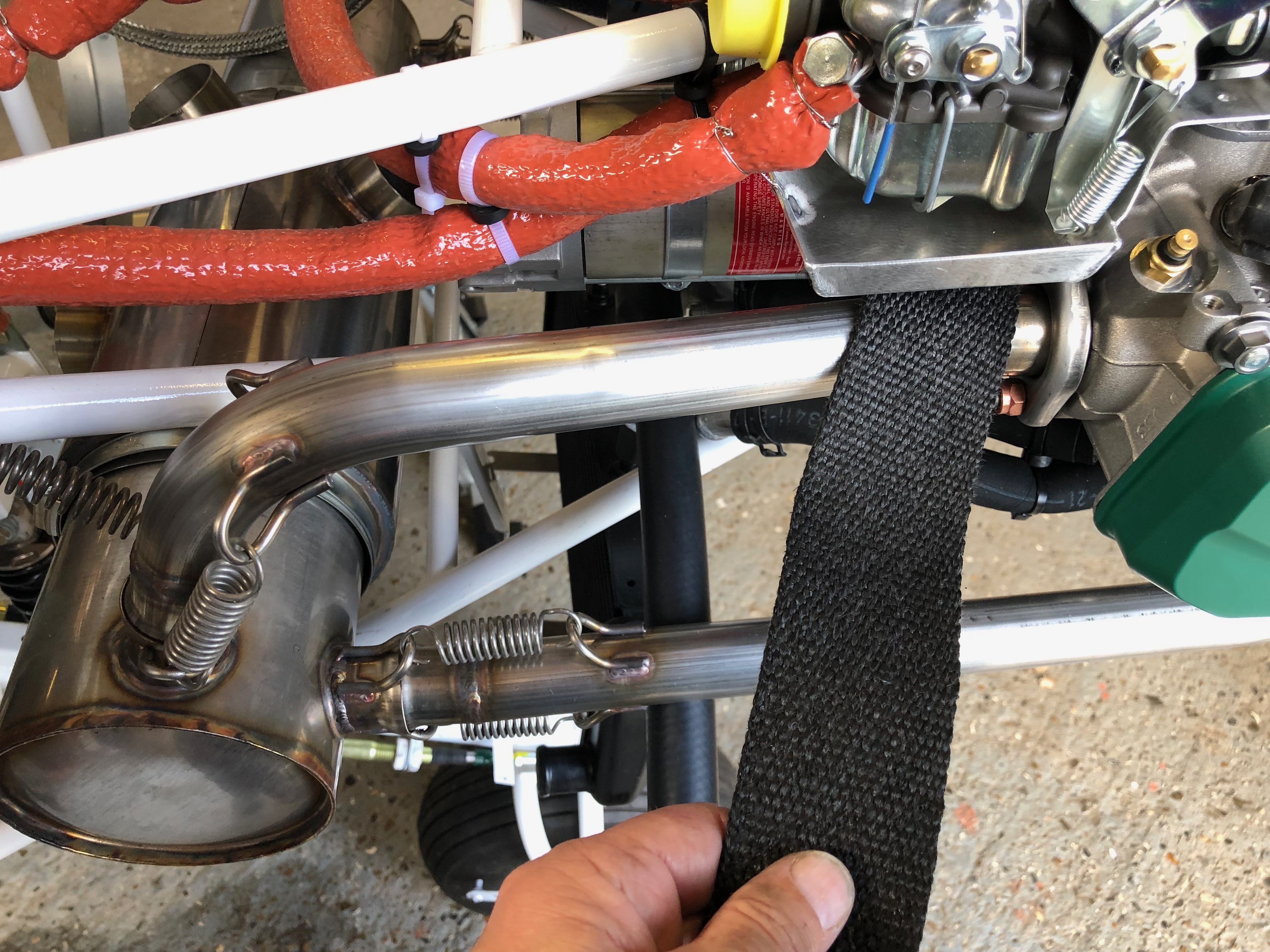
To protect the adjacent pipes from the heat of the exhaust I decided to cover the downpipes with exhaust wrap.
The starboard rear downpipes completed.
Run out of time but will take the landing lights home and fit the spade connectors as it’s a small job that can be done at home.
Today plan is to finish off some tasks that will see the completion of the oil system, exhaust system, NACA duct, and installing the rest of throttle cables ready for the throttle quadrant install.
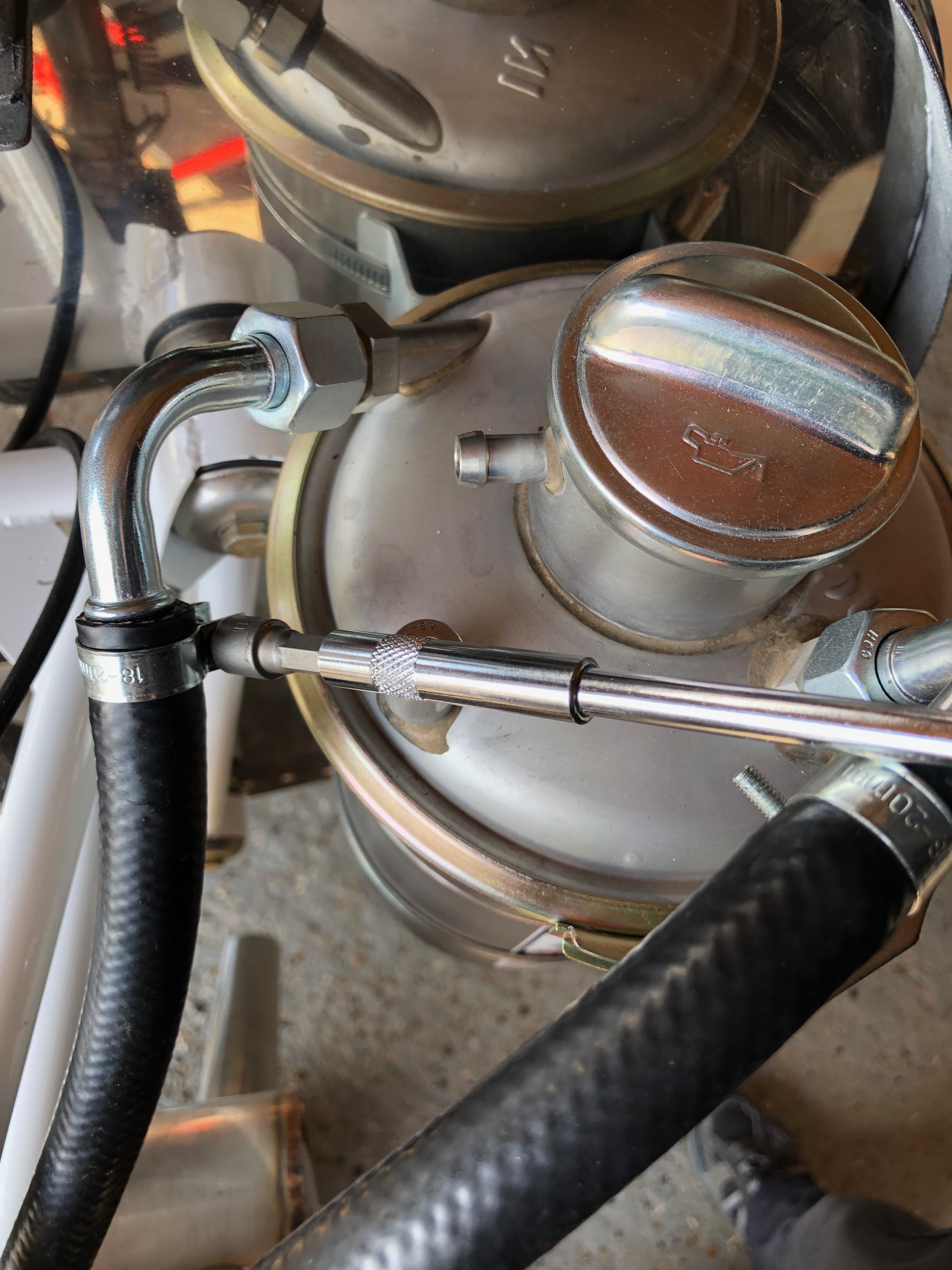
The hose clamp are added to the oil return line…
and the oil bottle. I’ve tried to position the clamps to make sure they are easier to get to for maintenance but out the way so someone working on in the engine bay won’t snag their hands or clothing on them.
The oil pump to oil radiator pipe is clamped and fire sleeving is added as the pipe runs very close to the exhaust down pipe.
Fire sleeving should protect the oil hose but I will be adding some exhaust wrap to further protect the pipe. The oil system is now complete.
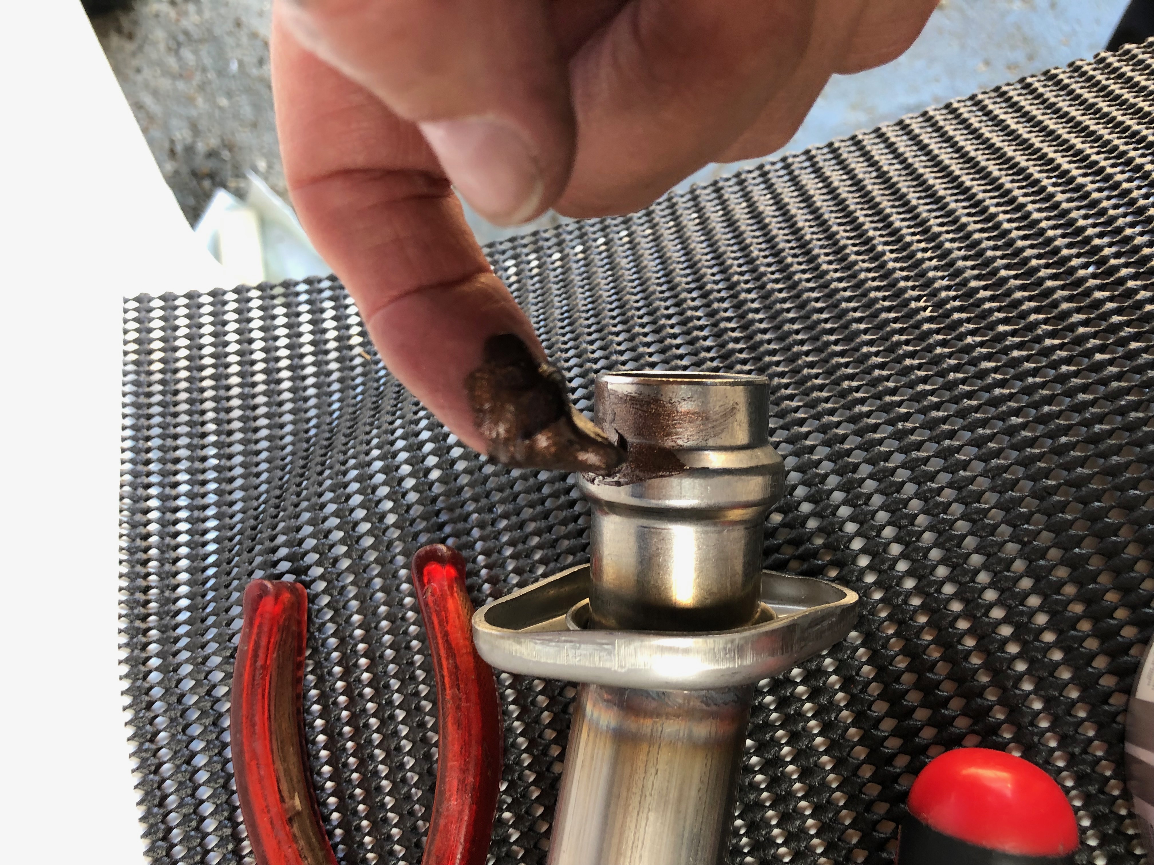
To finish the exhaust system install I need to apply some copper ease to the pipes to enable them to move slightly in service.
and also on the exhaust connection pipe.
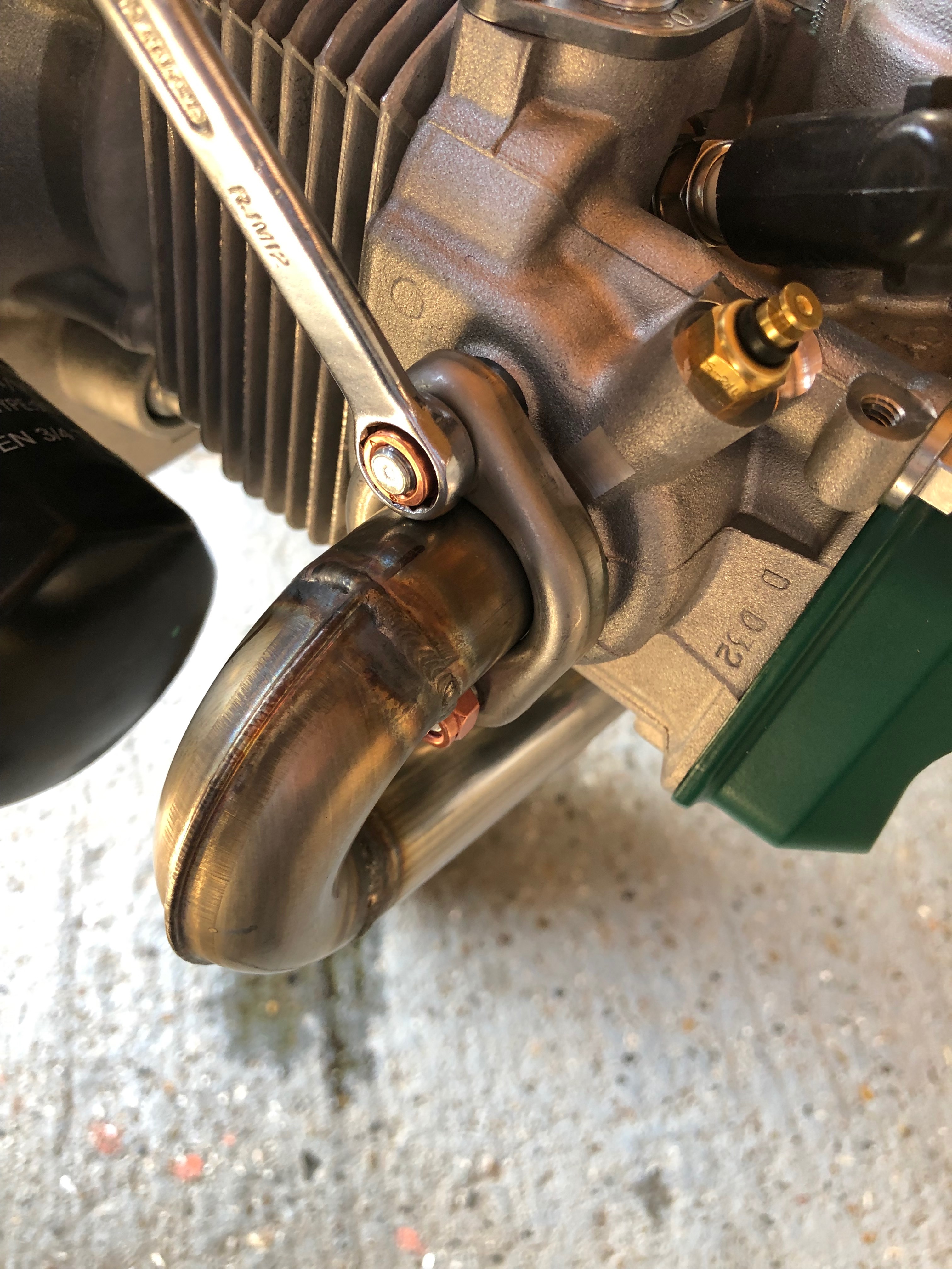
After checking the run of the pipes the nuts are tightened to complete the exhaust install.
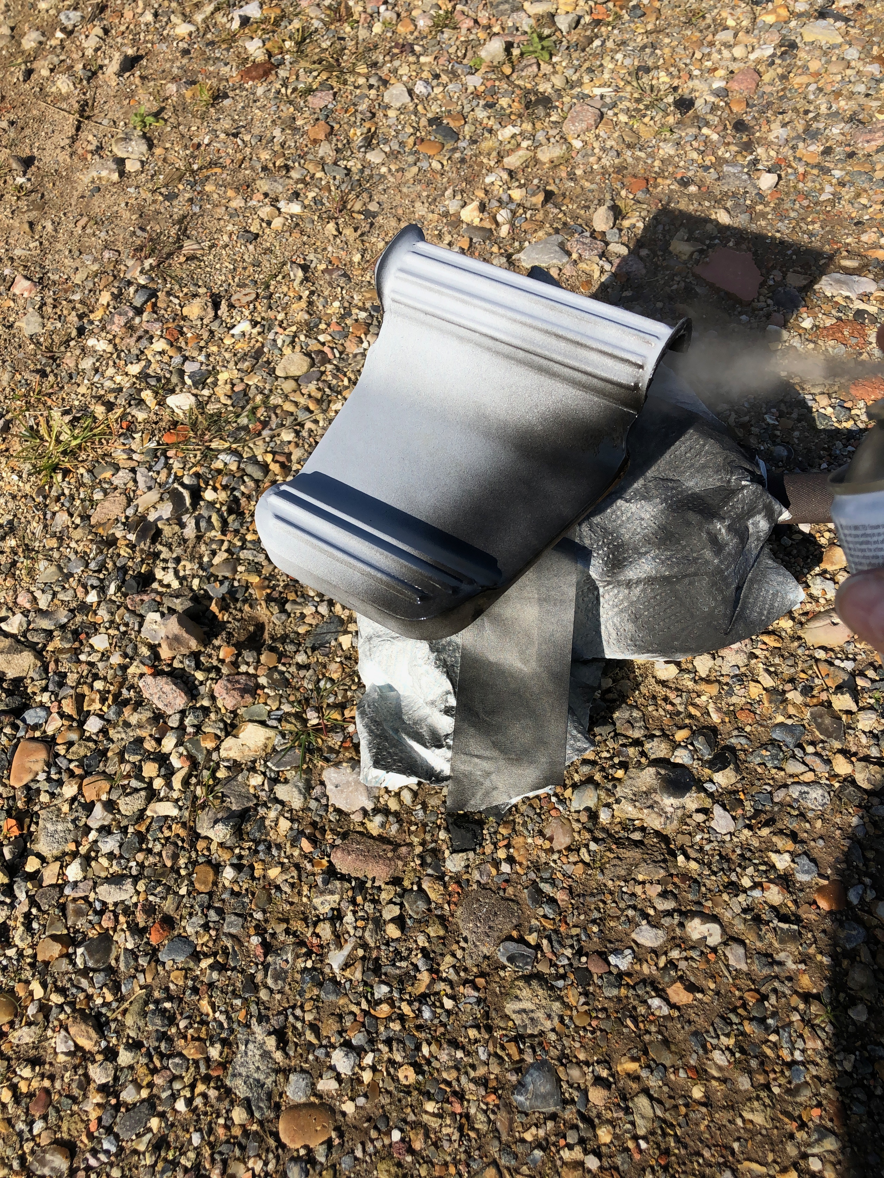
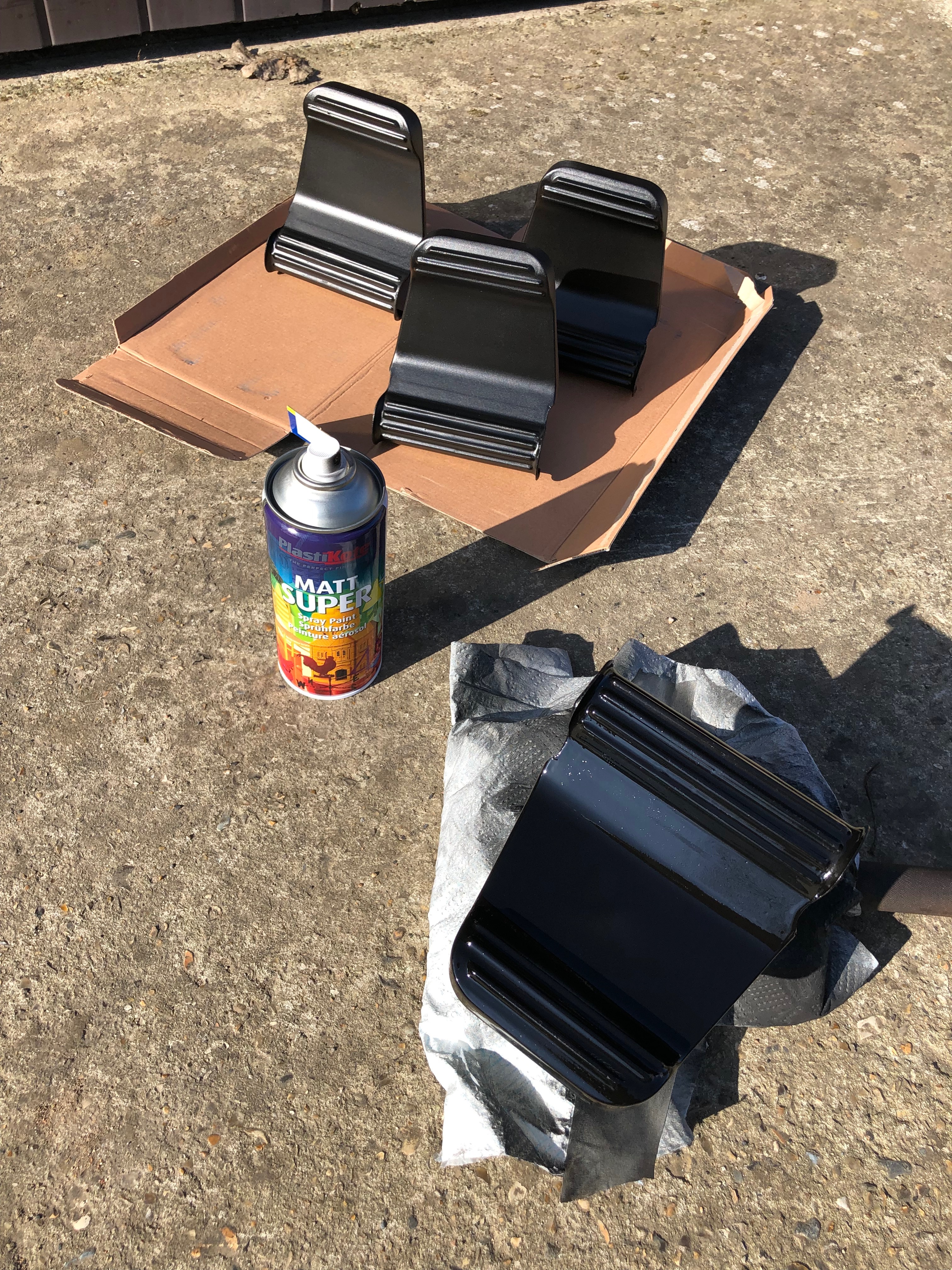
One of the jobs I can do between other jobs is to paint the rudder pedals. Two coats are needed leaving then to dry for about an hour between coats.
Last coat applied and drying off in the sun.
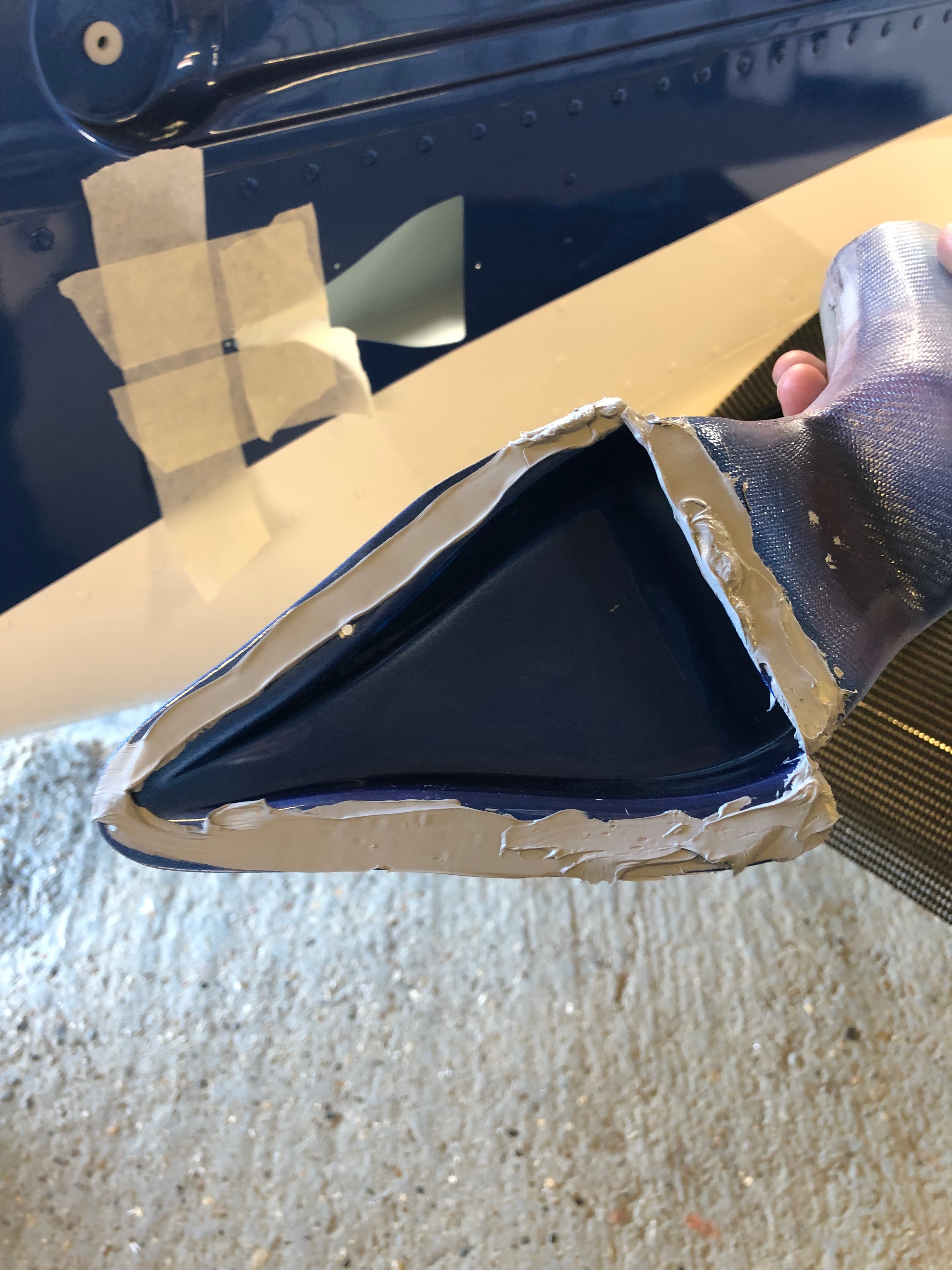
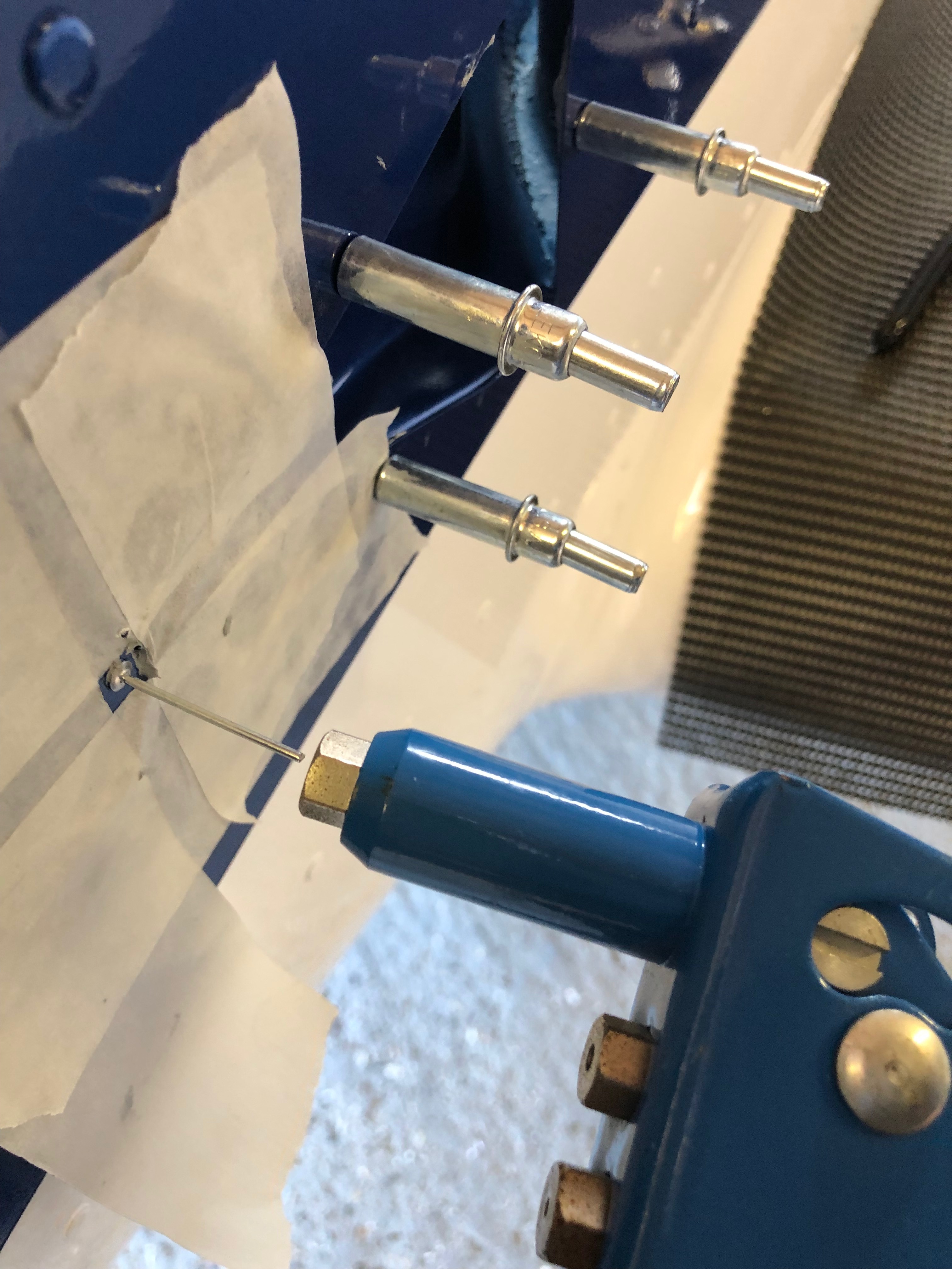
I had already drilled the NACA ducts but the mastic to seal them was too cold to apply so I had to warm it up slightly to apply it.
When I riveted the right side NACA duct I slipped twice and scratched the paintwork slightly which will need touching up and polishing out at some point. To stop this happening again I applied some asking tape around the rivet.
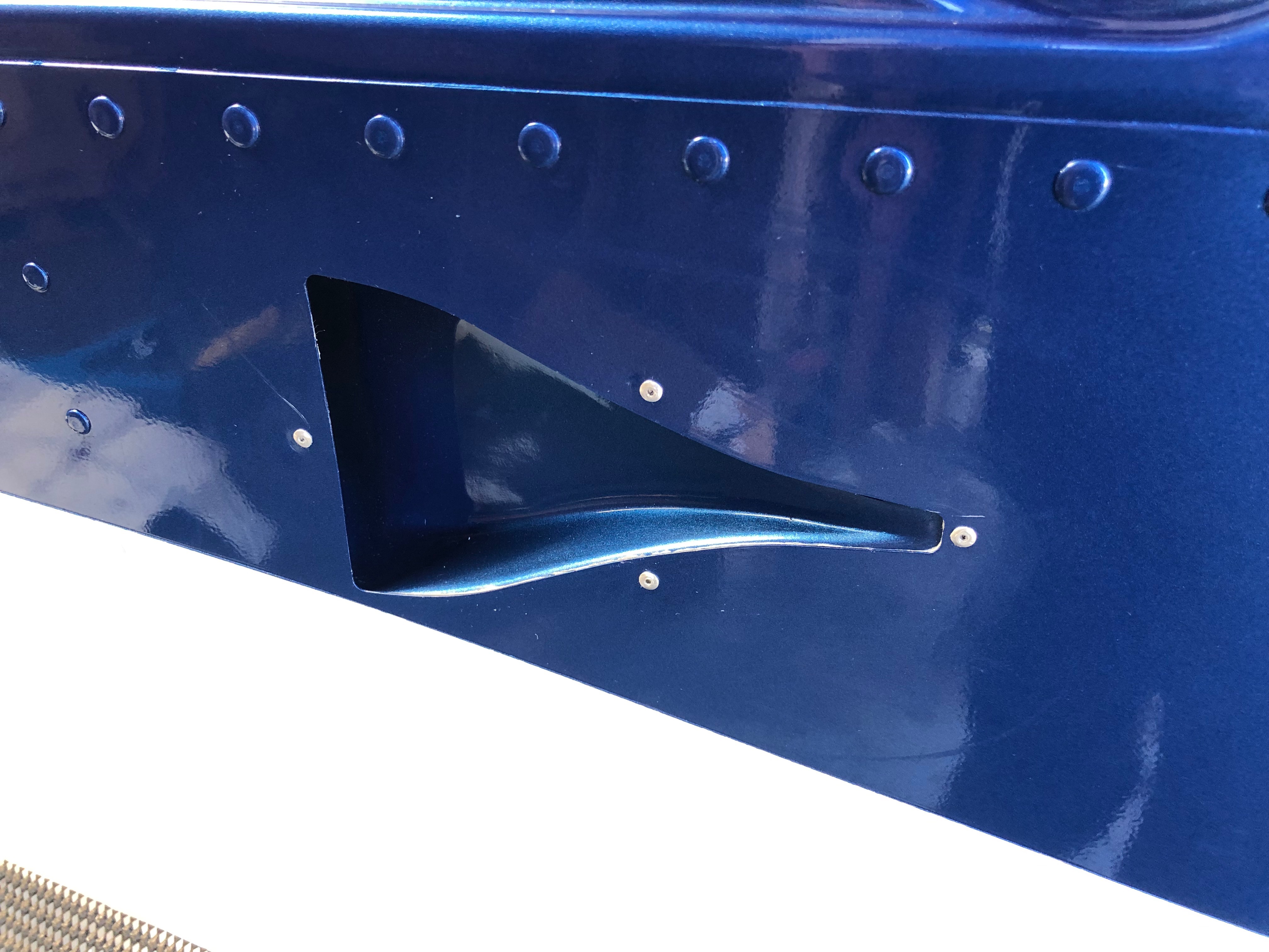
Right side duct. As you can see a slight scratch on the left rivet.
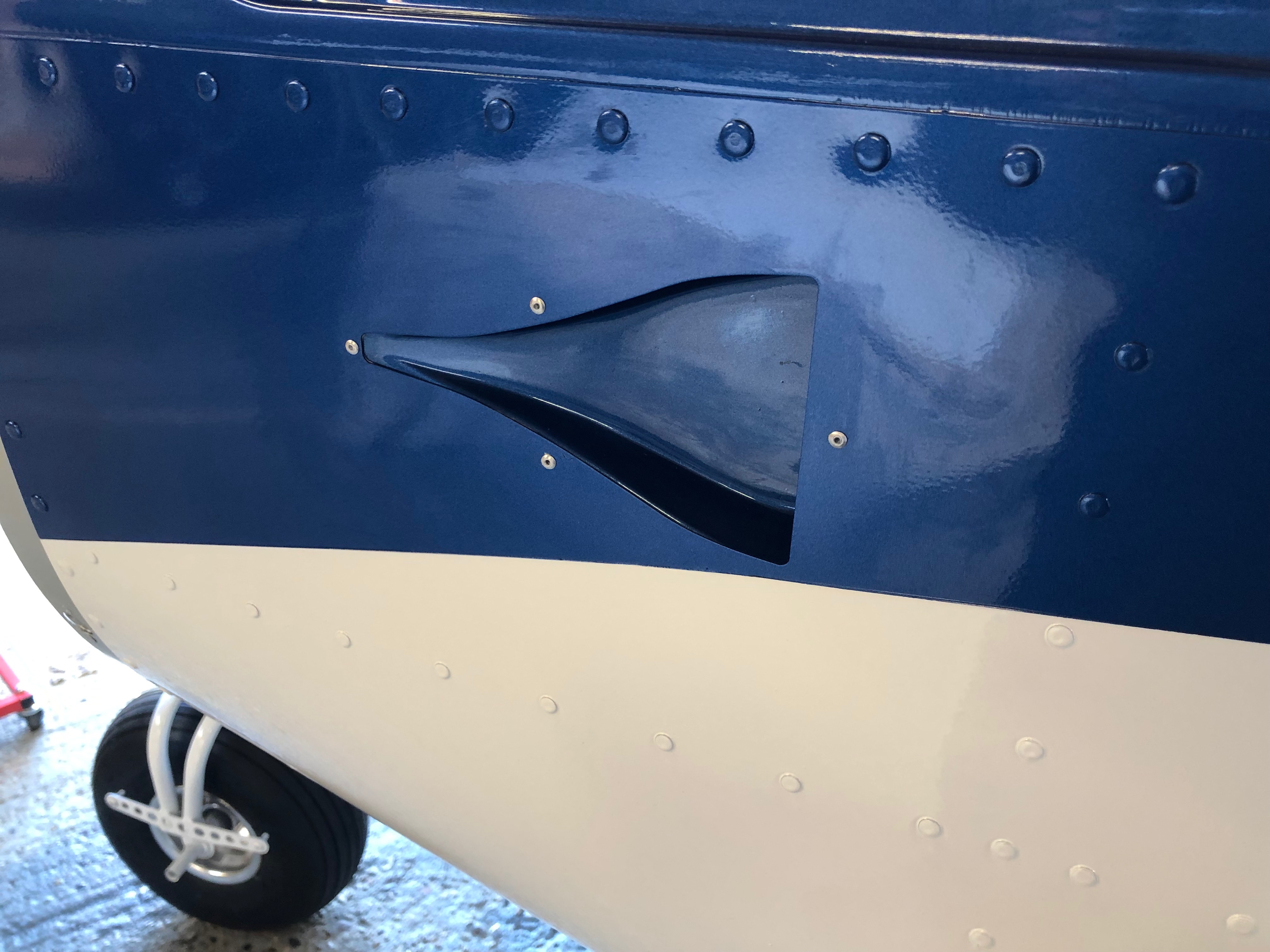
and the lefthand duct. A better job on this side. The duct install is now complete but still needs the Scat hose to be added for the cabin air vents.
The throttle cables have to be cut and made up. A few drops of oil down the outer will allow the cable to run smoothly and operate better in service.
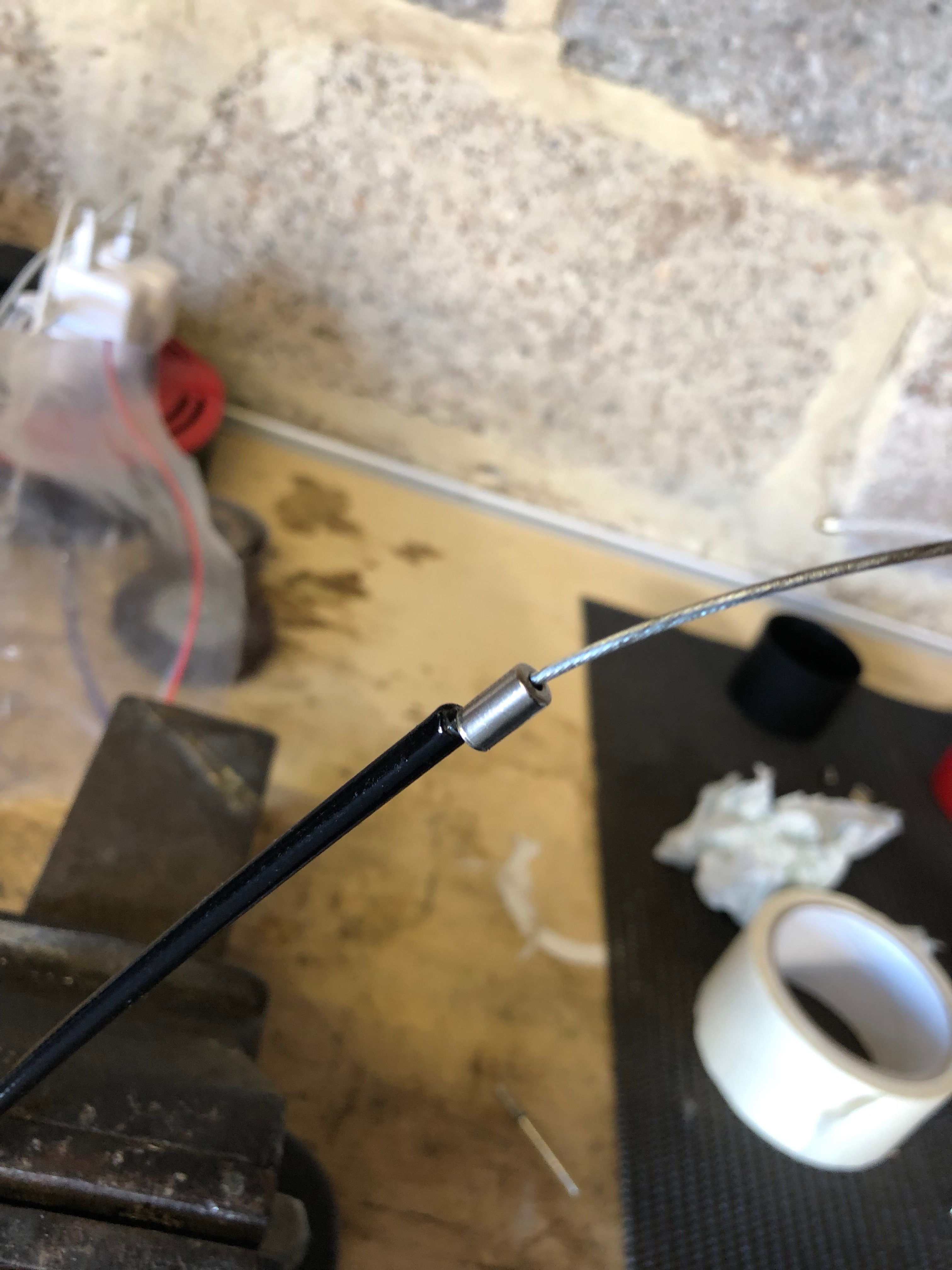
Ferrules are added to the outers before fitting.
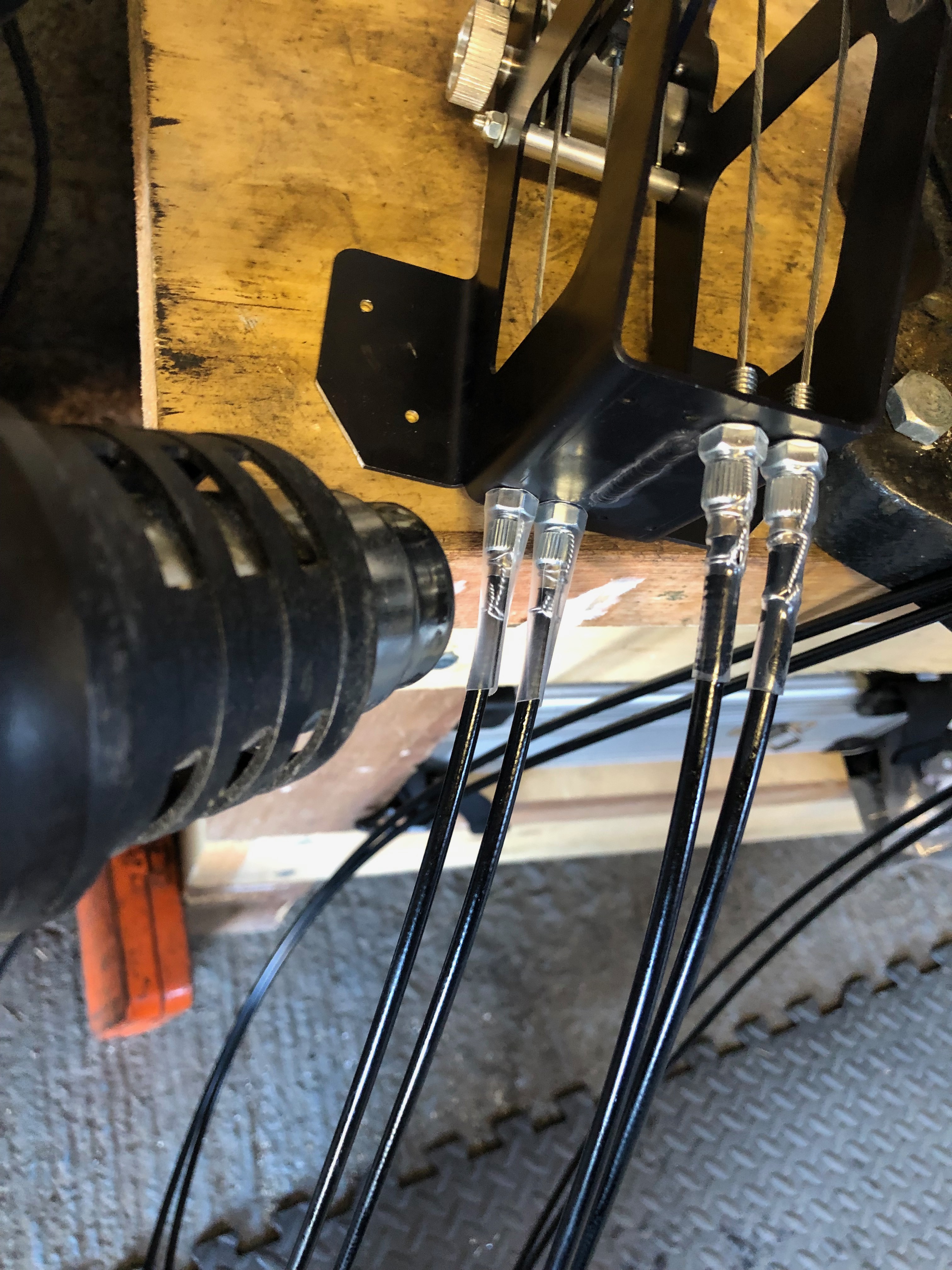
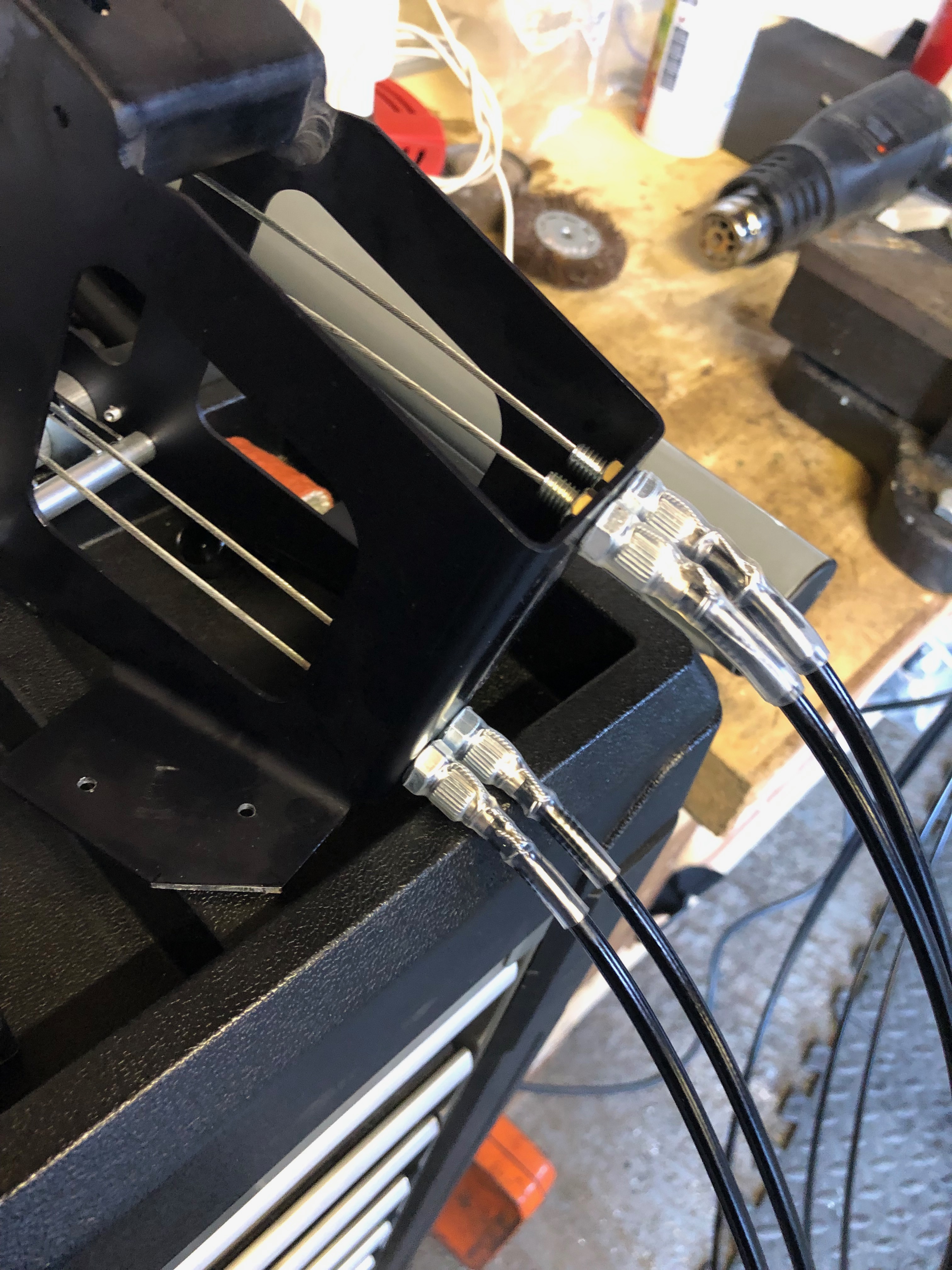
Wire locking is added and a piece of heat shrink tubing is slipped over the assembly to ensure is doesn’t undo.
The throttle quadrant is complete and will be installed when I come back this evening.
The missing parts arrived in the post today so I was able to get on with some of the tasks that have been stalled.
First job today is to add strengthening to the oil coolers bracket. The strip of metal is bolted to the bracket and holes are drilled to accept 2 rivets.
Rivets are installed.
The finished brackets ready for install.
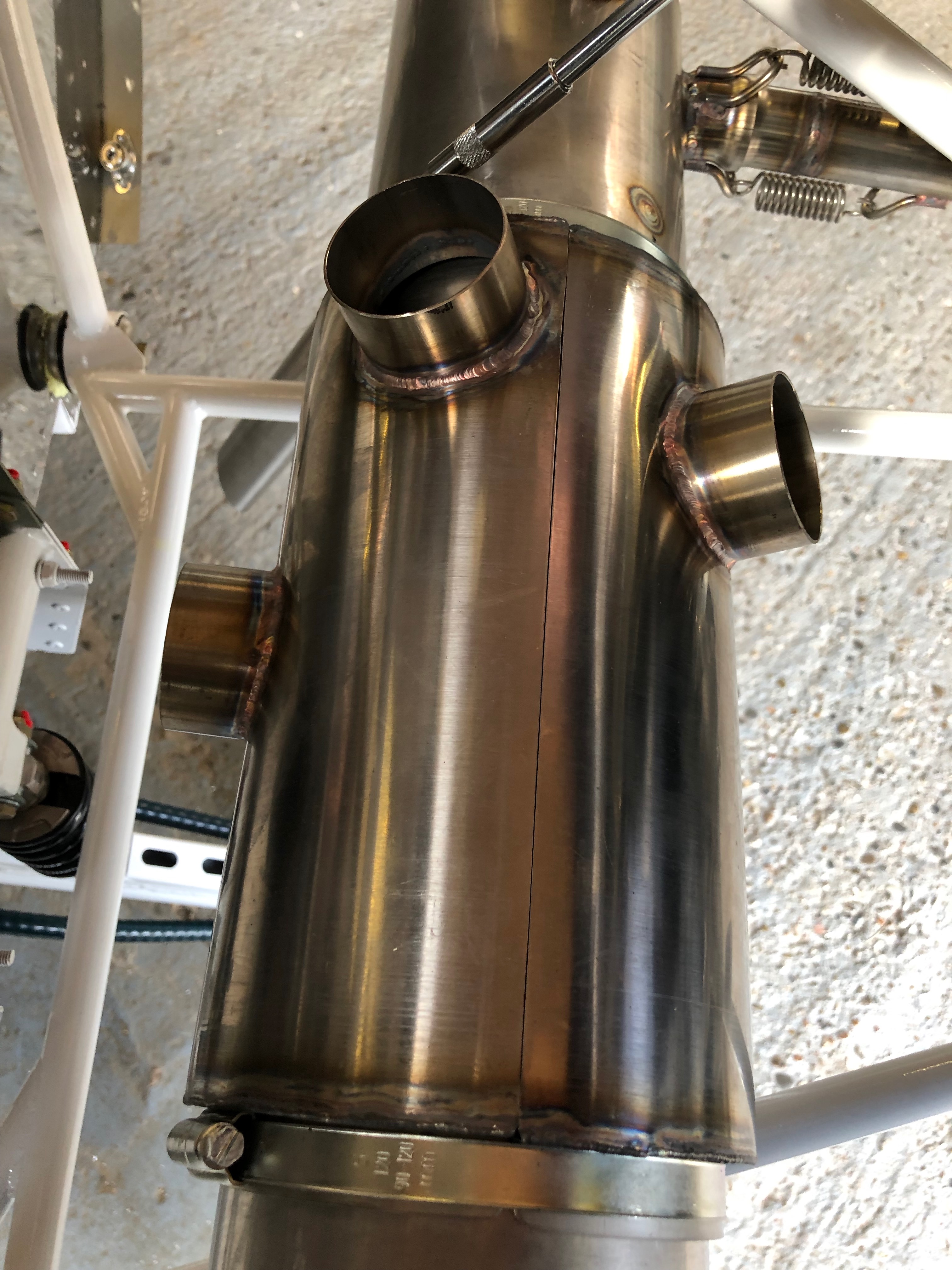
Next is to clamp the heat exchanger, for cabin and carb heat, onto the exhaust with large jubilee clips. They are no tightened at this point as it may need to be rotated later.
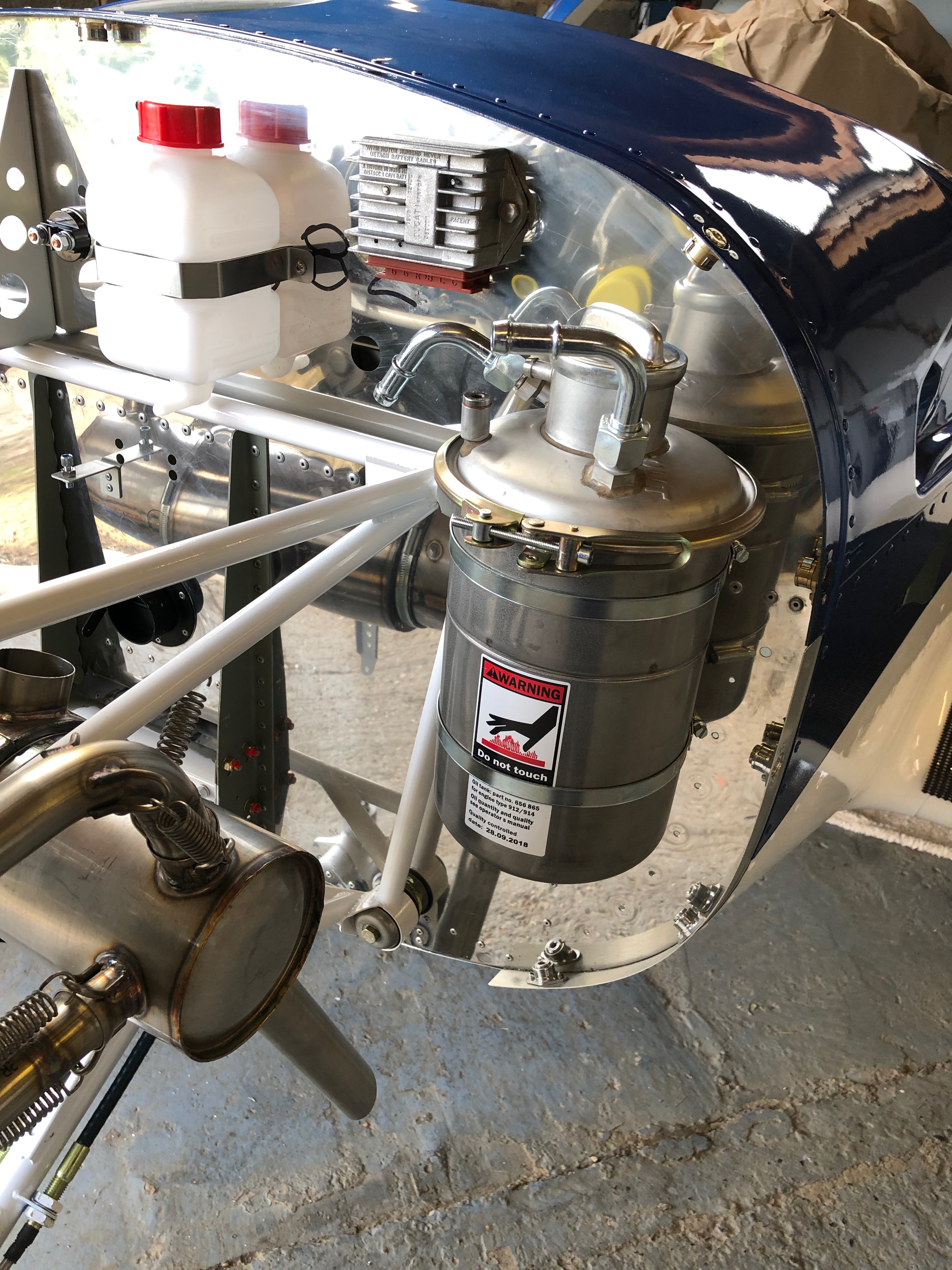
The oil tank is secured with large jubilee clips. Thinking about the location of the screw clamps I decided to turn them round.
Tank now install and the screw clamps are now ‘hidden’ at the rear of the tank. I’ve also turned the tank clamp around which makes it easier to undo for servicing.
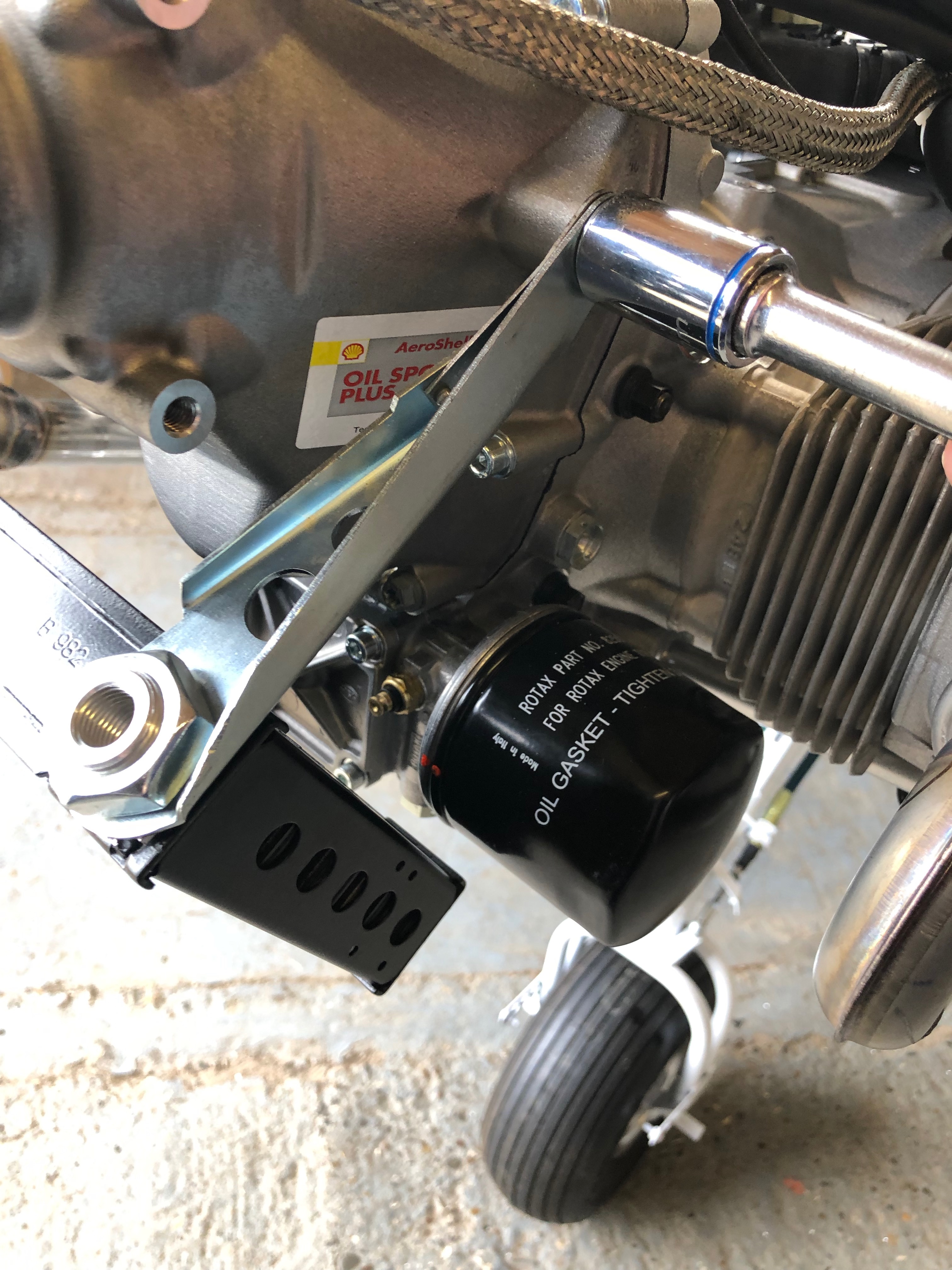
Now the oil cooler brackets have been strengthened it’s time to install the oil cooler.
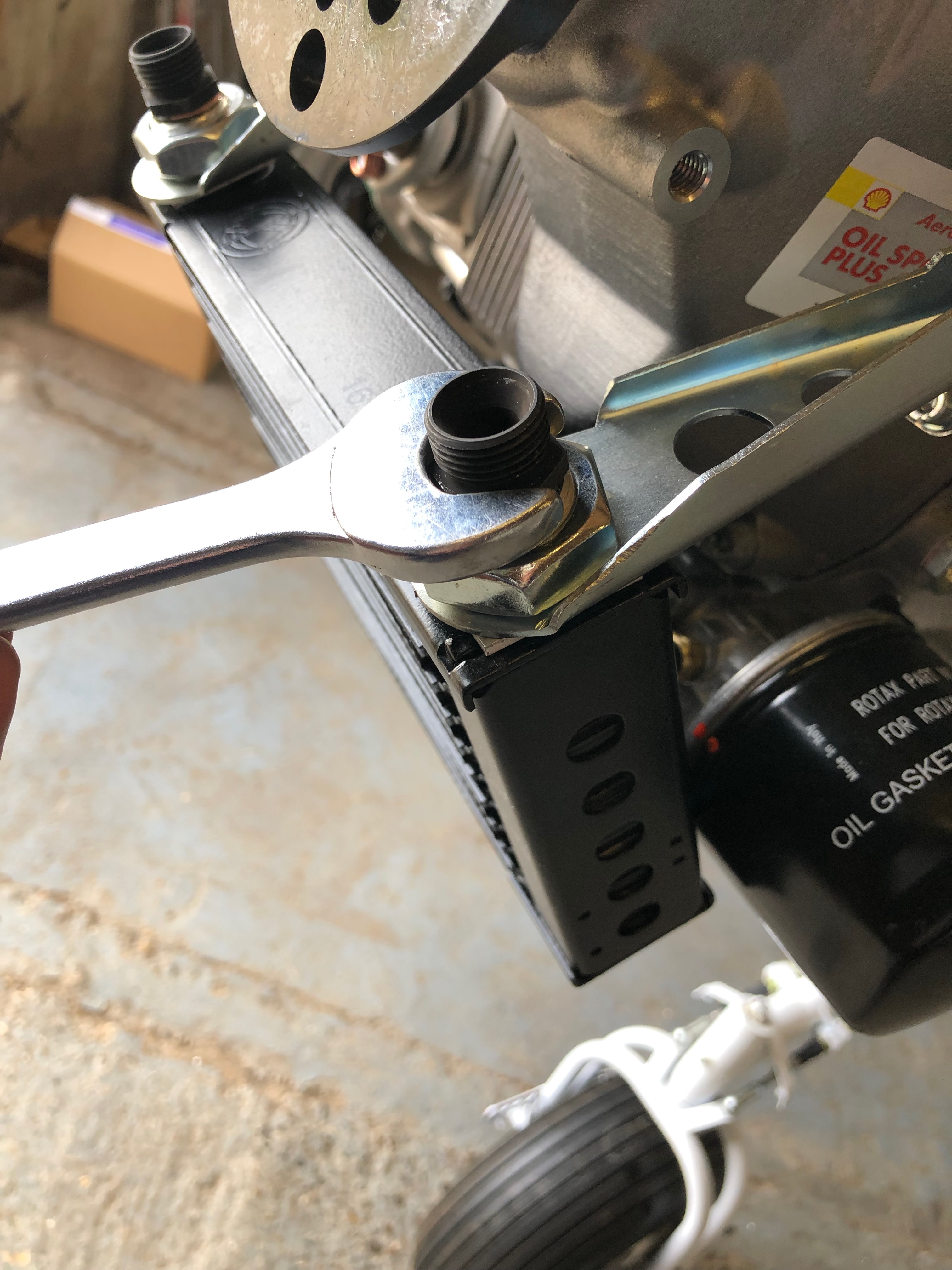
A reducer is installed to for the oil hose connectors.
Oil pipe connectors installed.
2 bolts are installed and locked with Loctite 243 to stop dirt and muck filling the lifting bracket mounts.
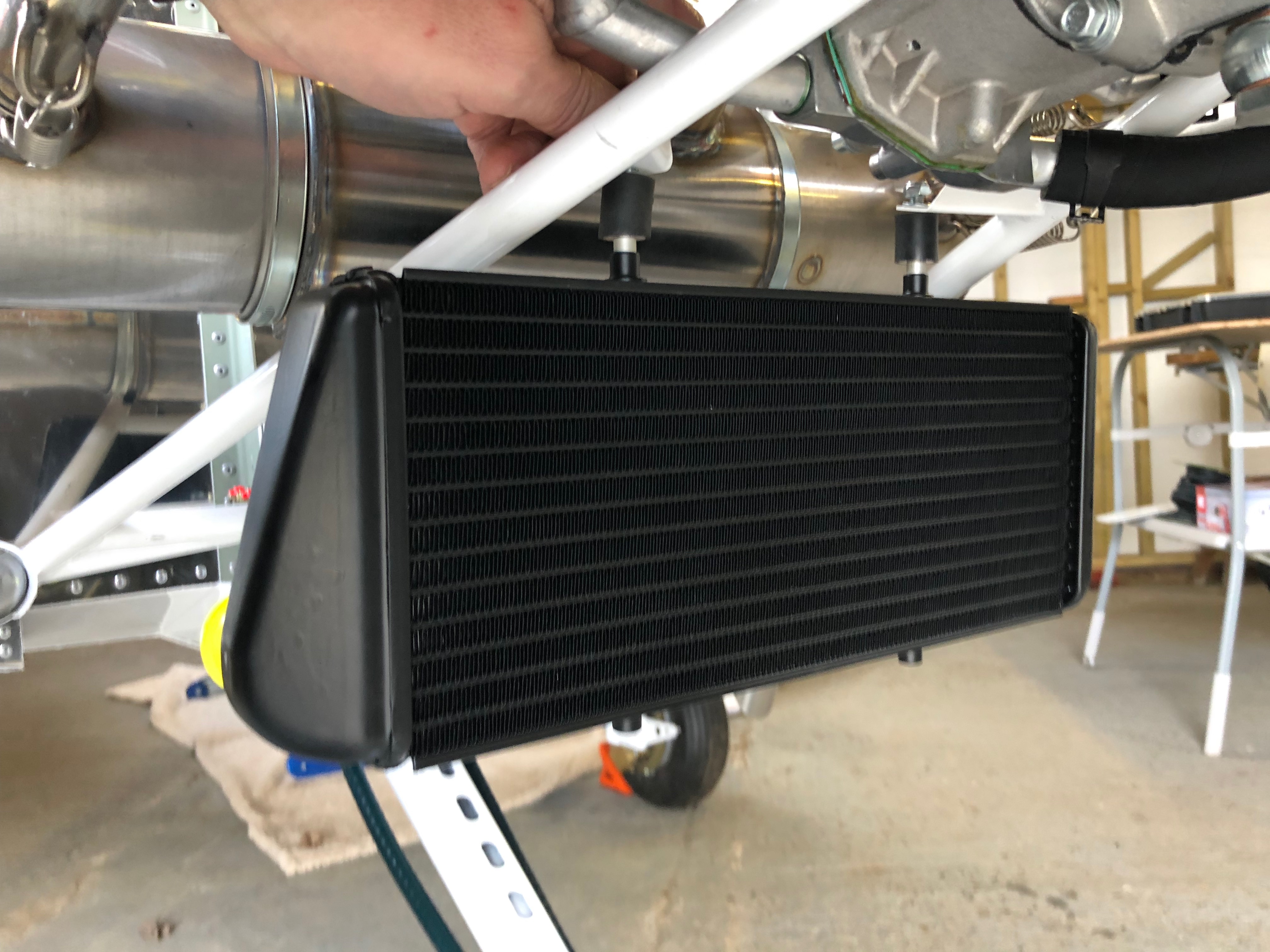
The water cooler is installed next and requires a couple of brackets and 5mm spacers to be made.
I think that’s close enough…
The 2 spacers are fitted on the rubber vibration isolators, screwed into the top of the water radiator and secured with 2 M6 nyloc nuts.
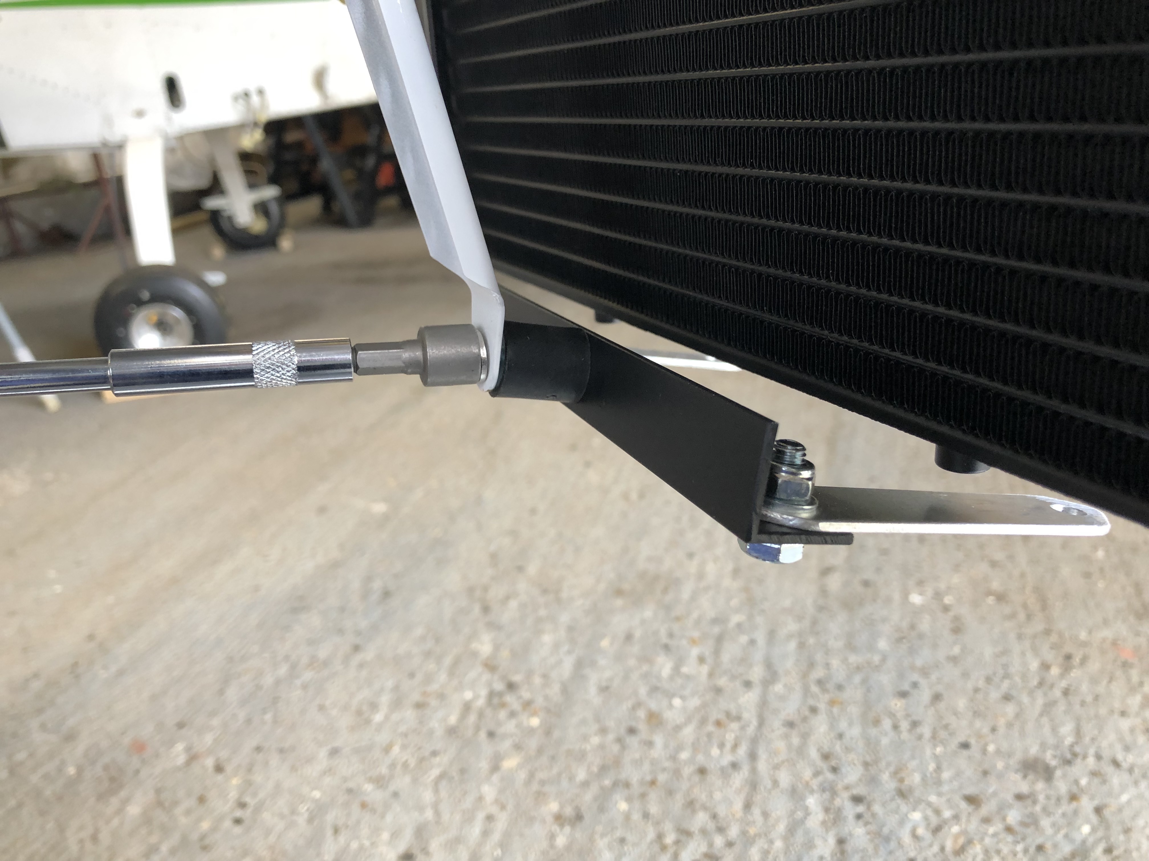
The aluminium brackets are fitted to the lower support…
and secured under the water radiator. I need to finish the final securing tomorrow.
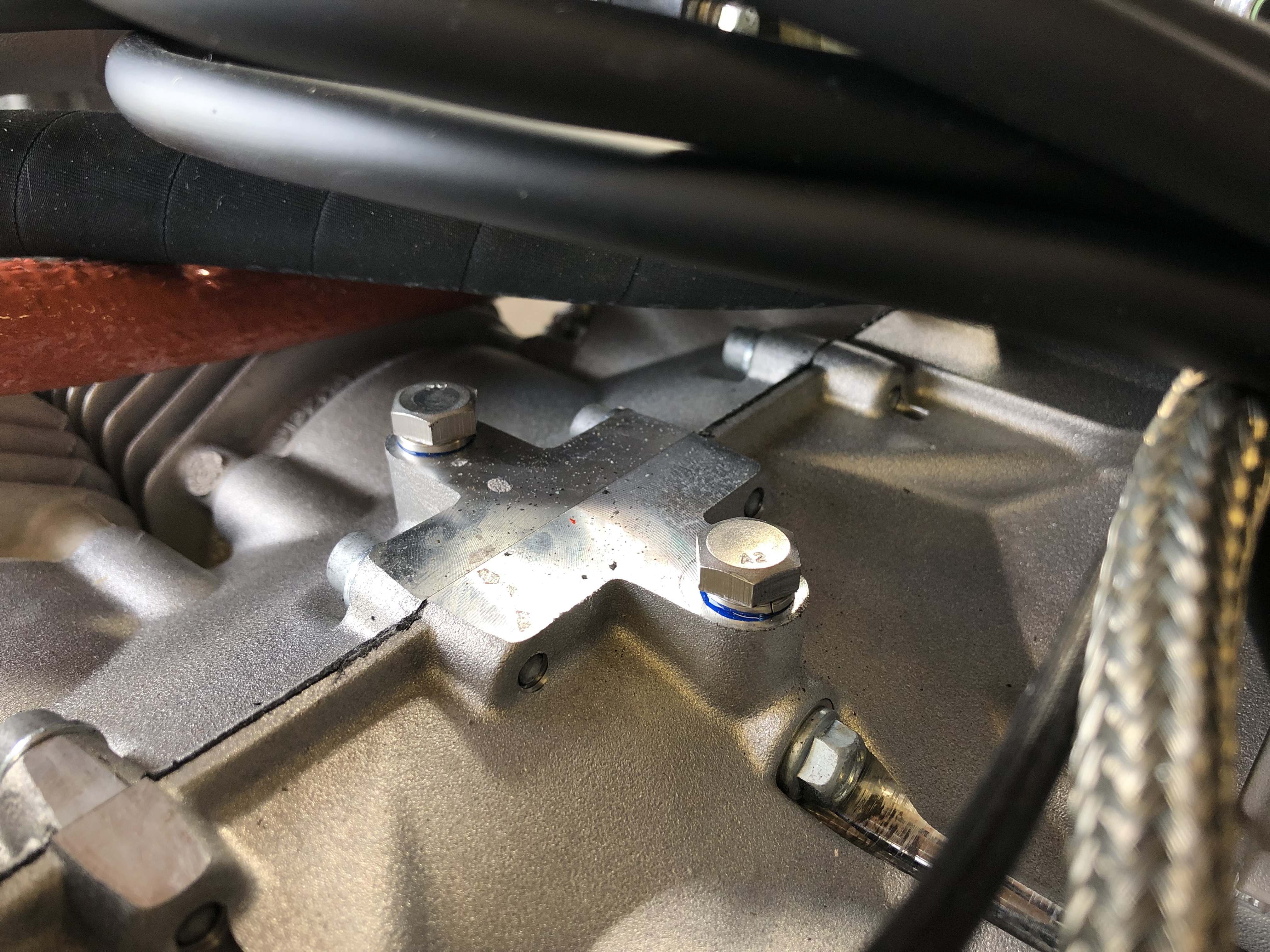
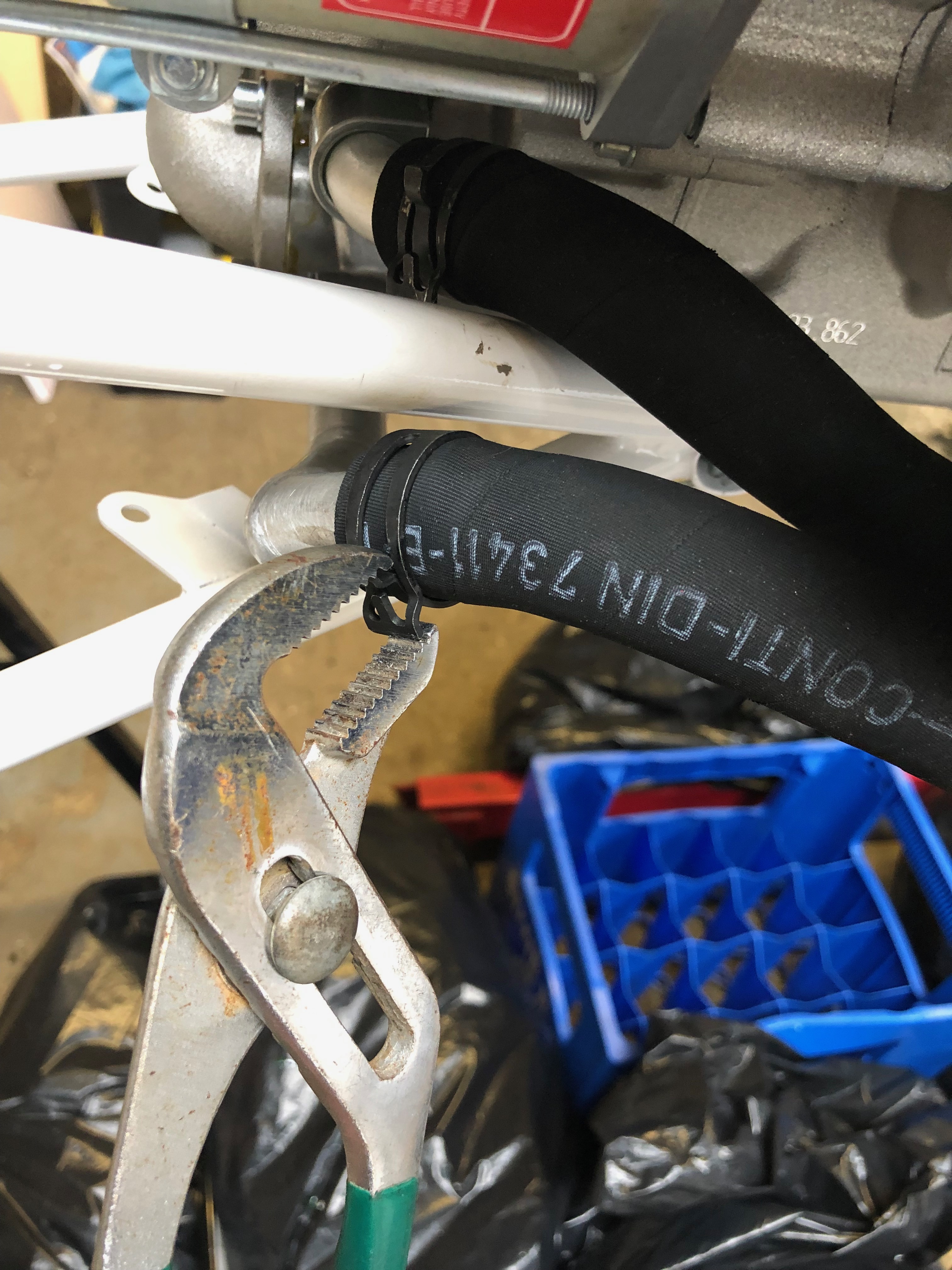
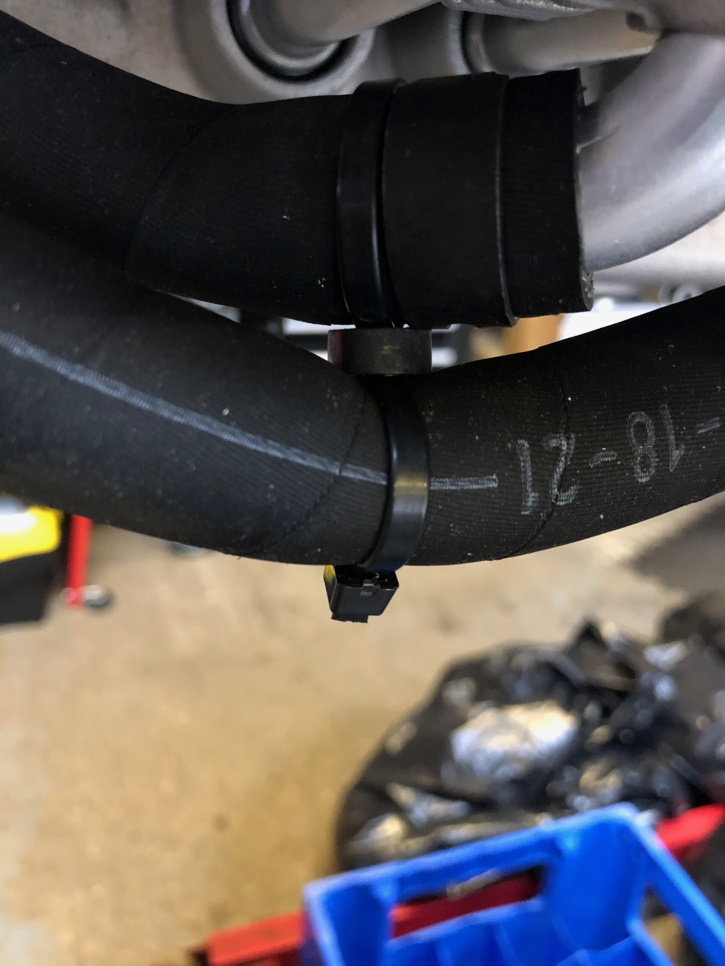
Now the Loctite is set the water pump pipes can be refitted.
A ‘stand off’ is required to stop these 2 pipes from rubbing.
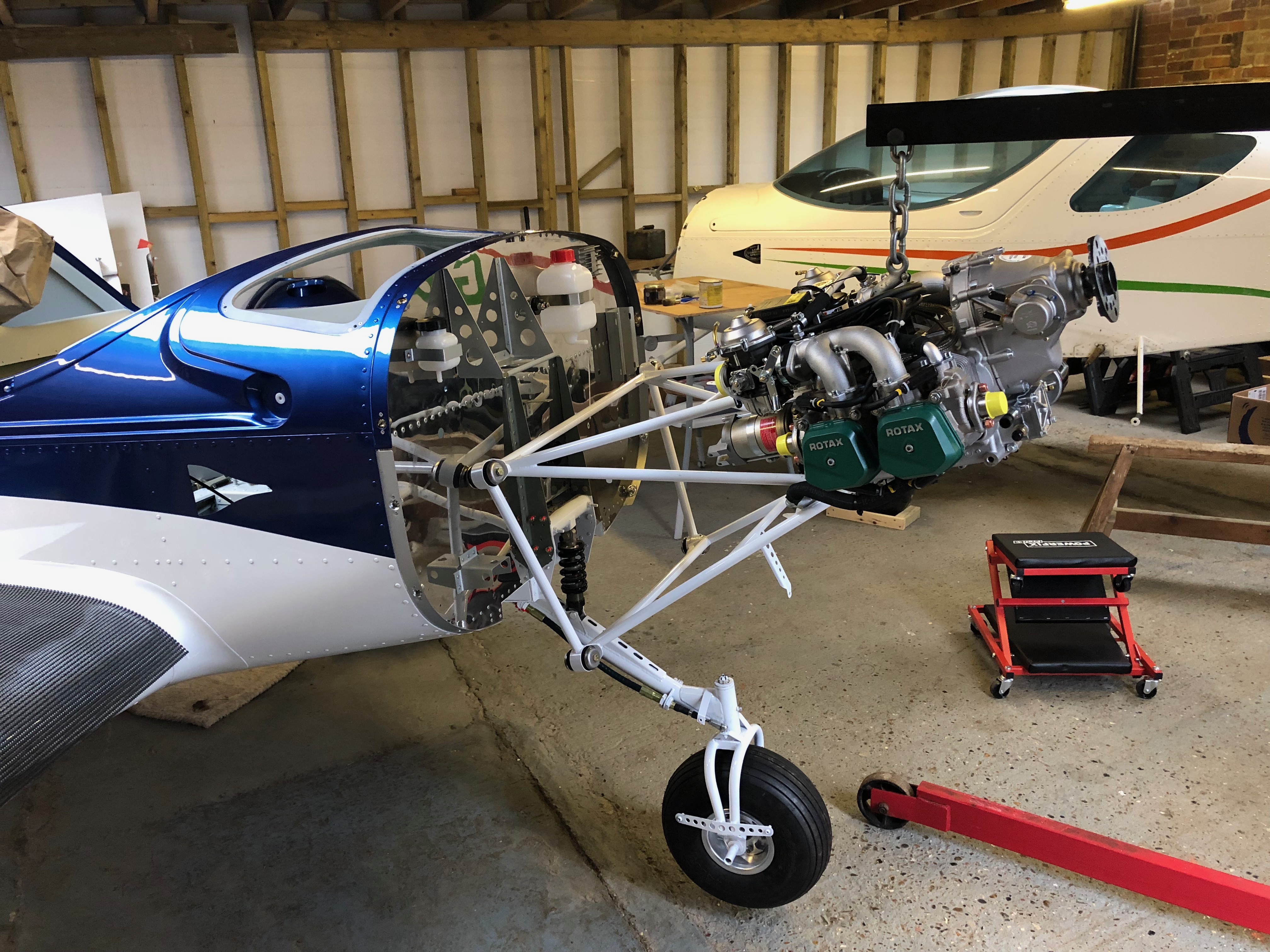
Time to hang the engine. The engine hoist and engine is positioned just in front of the fuselage and hoisted to roughly the correct height.
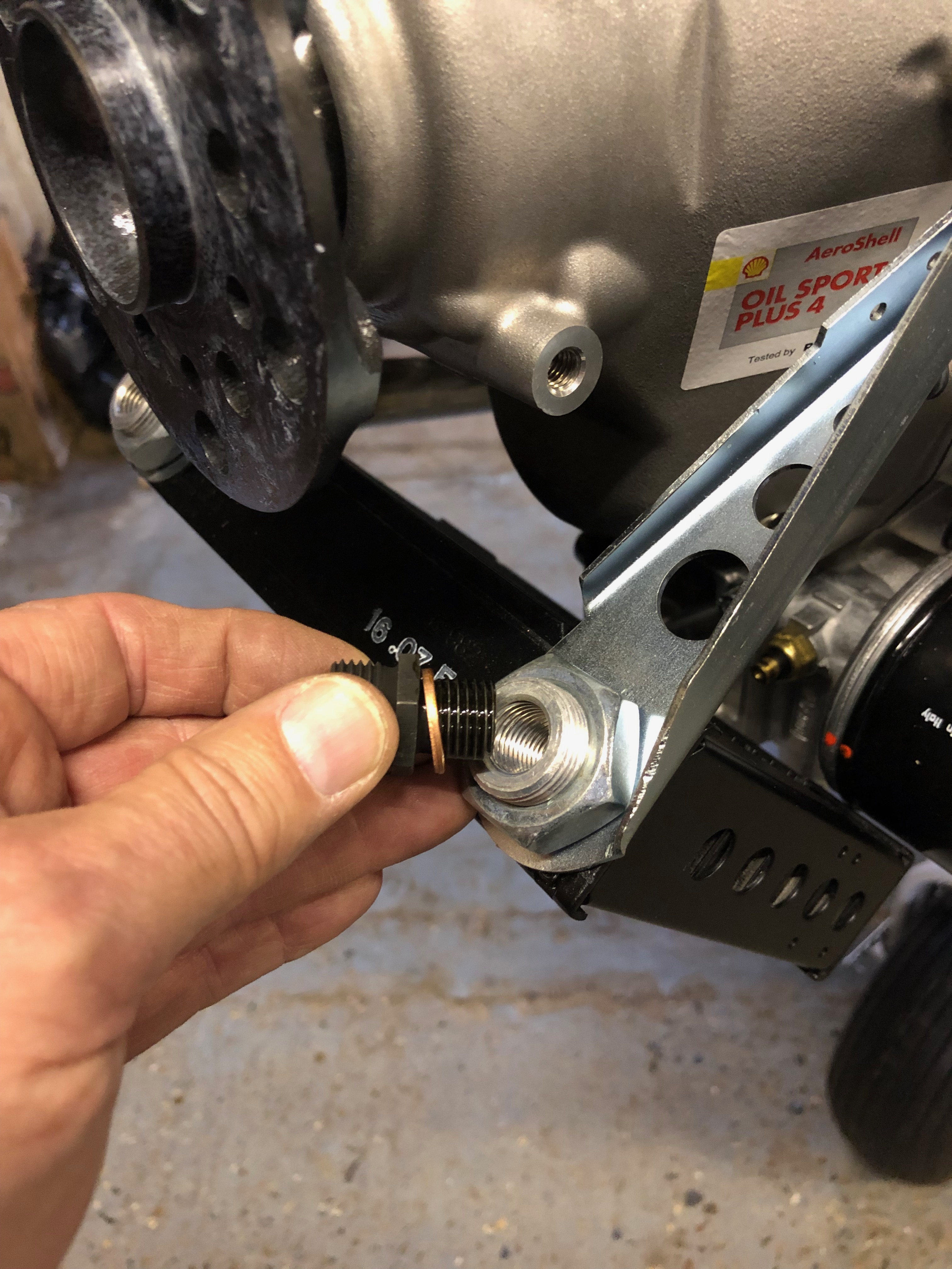
The engine mount steel cup washers are covered in jointing compound to stop them rusting once fitted.
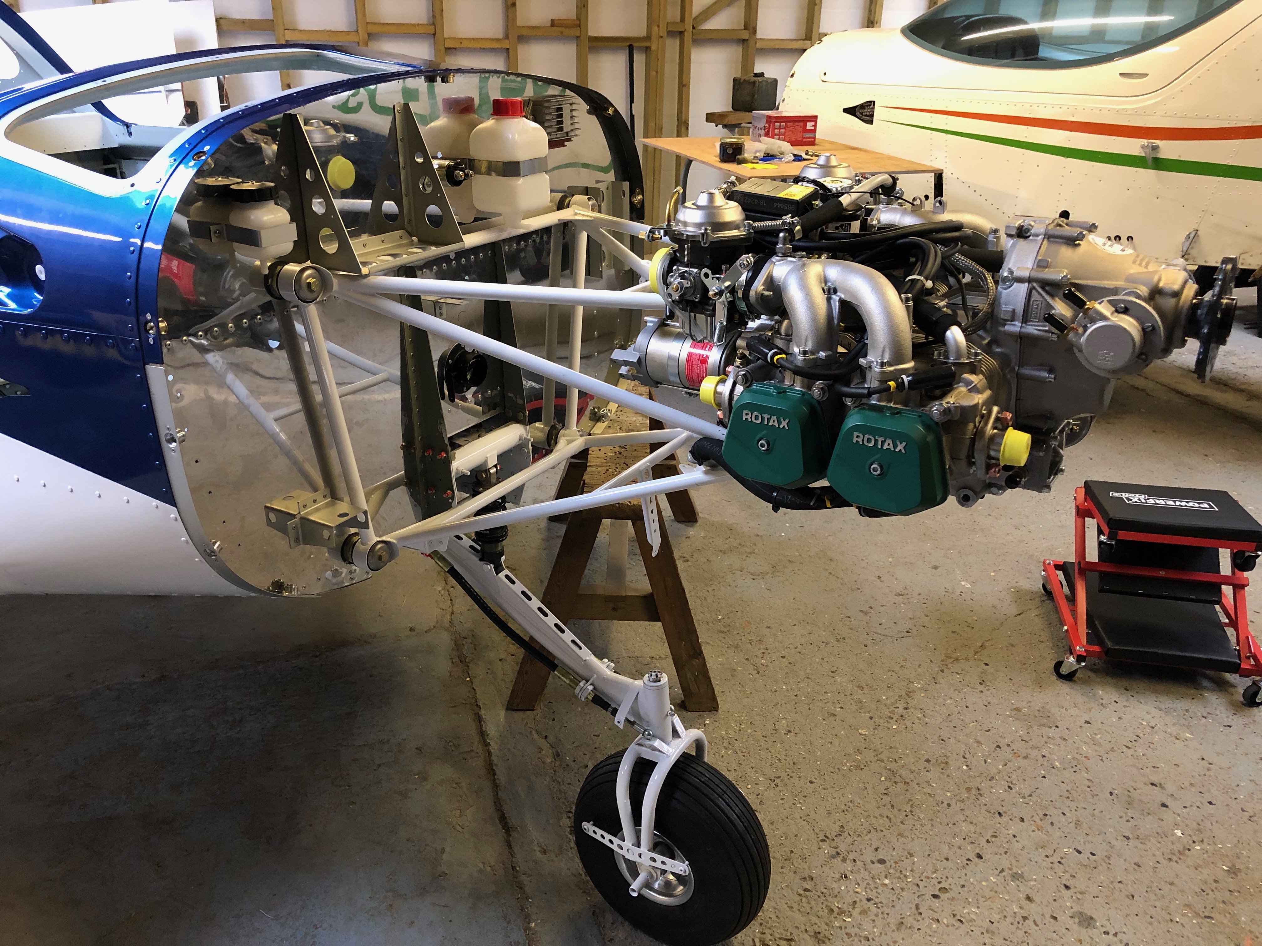
First of 4 bolts to be fitted. 3 were quite easy to fit with the forth taking about 10 minutes to position properly as the rubber mount had turned slightly.
With the engine mounted and bolts tightened it’s time to fit the exhaust system.
The bespoke Bristell exhaust downpipes are fitted first.
The exhaust box is hung using springs and flexible couplings to provide a leak free system.
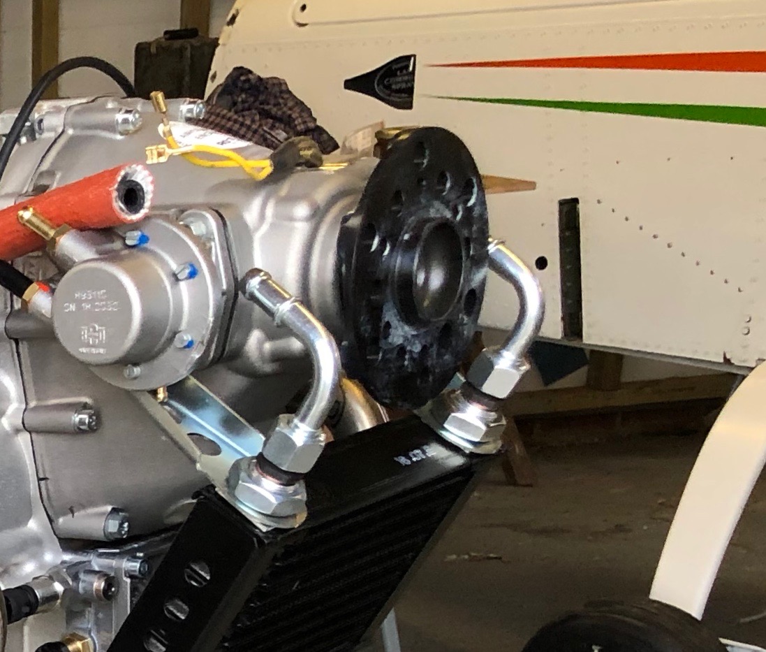
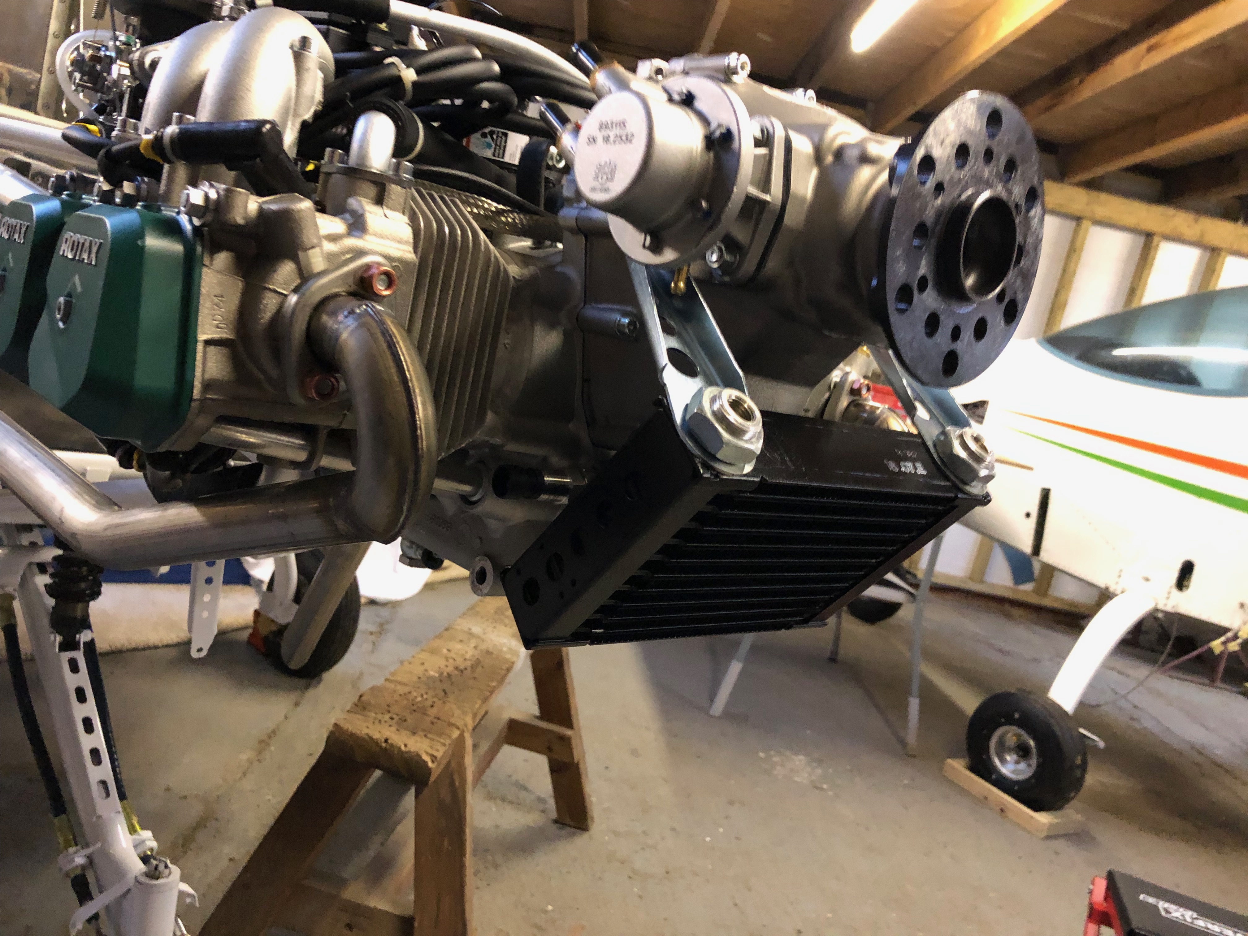
Next the oil cooler is fitted using the brackets provided.
and adapters are fitted to accept the aluminium connector pipes.
Good progress for the day. A tidy up of the workshop in readiness for tomorrow.
Following the build of my Bristell NG5 Kit No. 382 Registration G-MLSY