Back from Vienna just before Corona Virus closed all borders! With the transducer installed before I went away I rechecked the installation and carried out pressure testing to ensure there’s no leaks and all seems to be secure.
Wiring up the transducer into the EMS220 is straightforward using 3 wires, a 12v supply, signal and ground. The SkyView panels need to be configured with the ‘K’ factor of the FT60 unit. This is the number of rotations per US Gallon. Entering the config screen I found that the SkyView had already detected the unit and configured itself which was handy.
Once configured a check needs to be carried out between measured and actual fuel flow. I removed one of the banjos from the carb and captured the flow in a measuring jug to carry this out. With no restriction the electric fuel pump delivered 66 litres per minute and when restricted to give 3 psi within the fuel system the flow rate was 44 litres per minute. This is significantly more than the 27 rpm that the engine needs at full throttle.
Testing throughout the RPM range was carried out switching between left and right tanks and using the engine pump and engine and electric pumps options to ensure there were no issues with fuel supply. After the engine runs a thorough check of the installation was made to ensure there were no leaks or issues.All’s fine so now for the paperwork for the LAA. Worksheets covering the work carried out and a fuel flow check form needs to be completed. A suitable entry needs to be entered in the Airframe logbook signed by myself and a permit maintenance release needs to be signed off by and LAA inspector with the appropriate authority, in this case Ian Daniels.
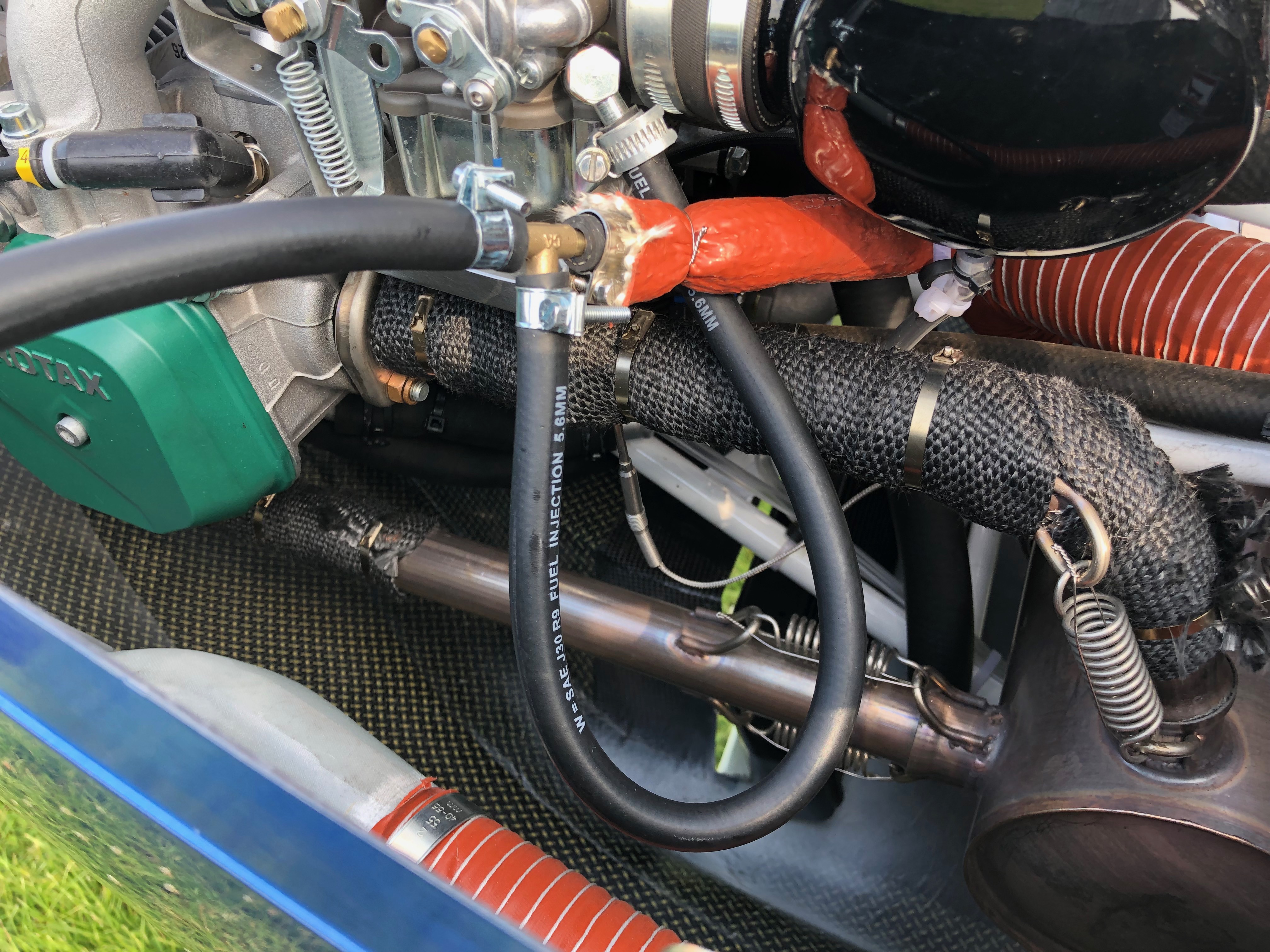
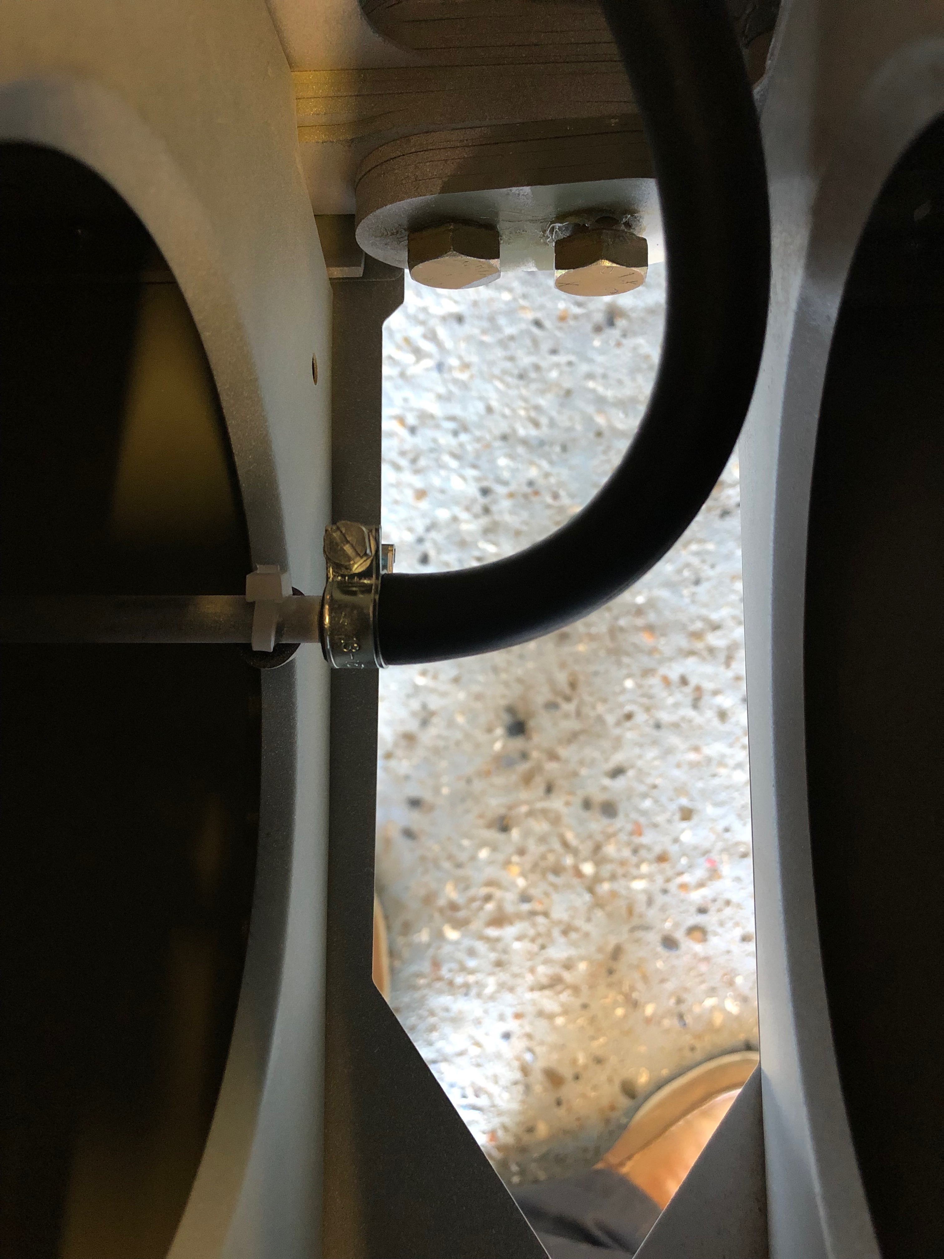
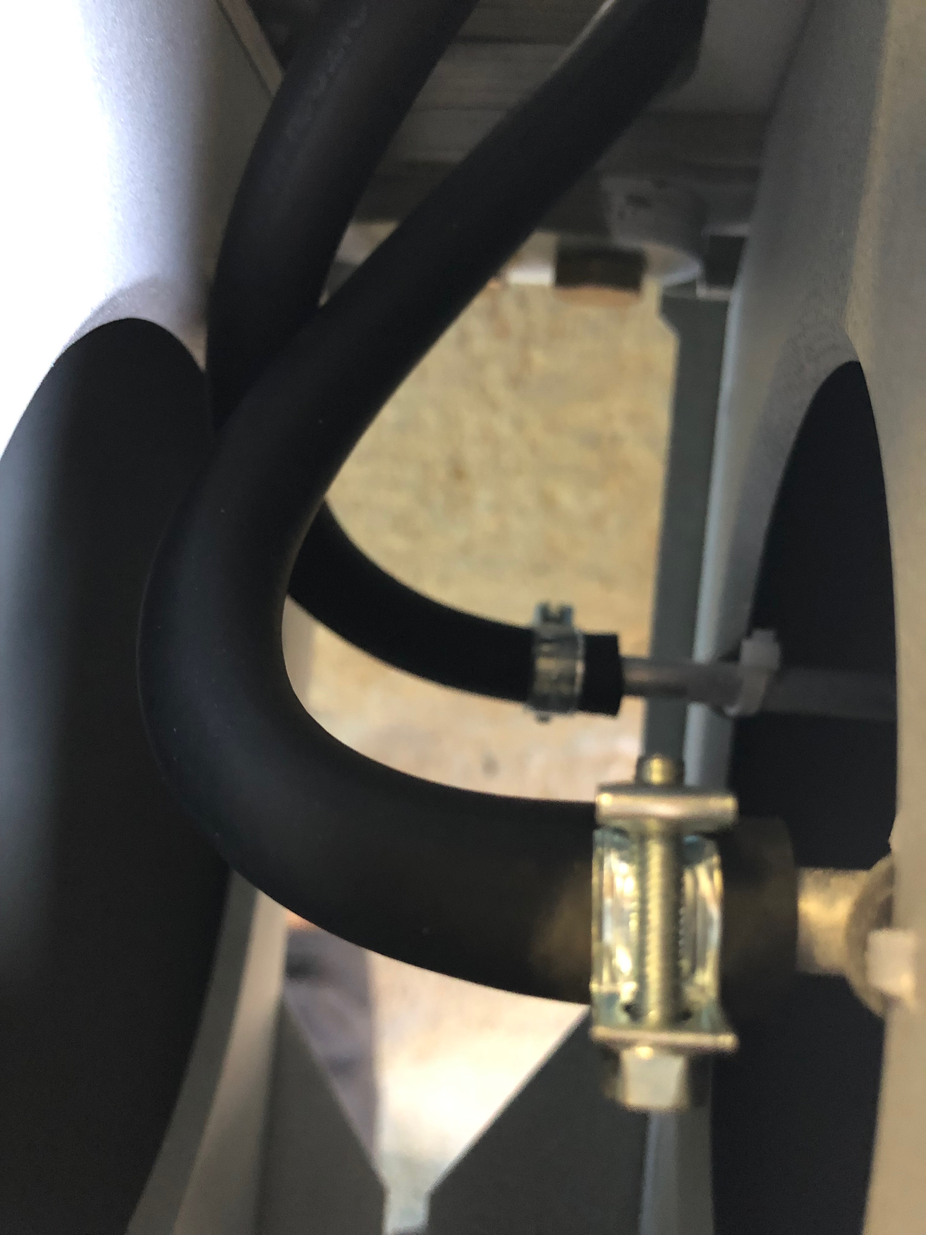
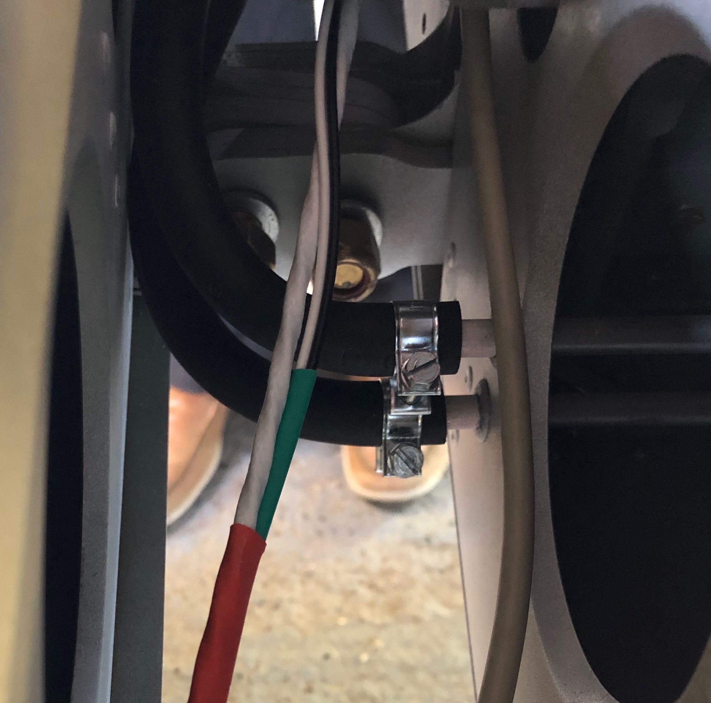
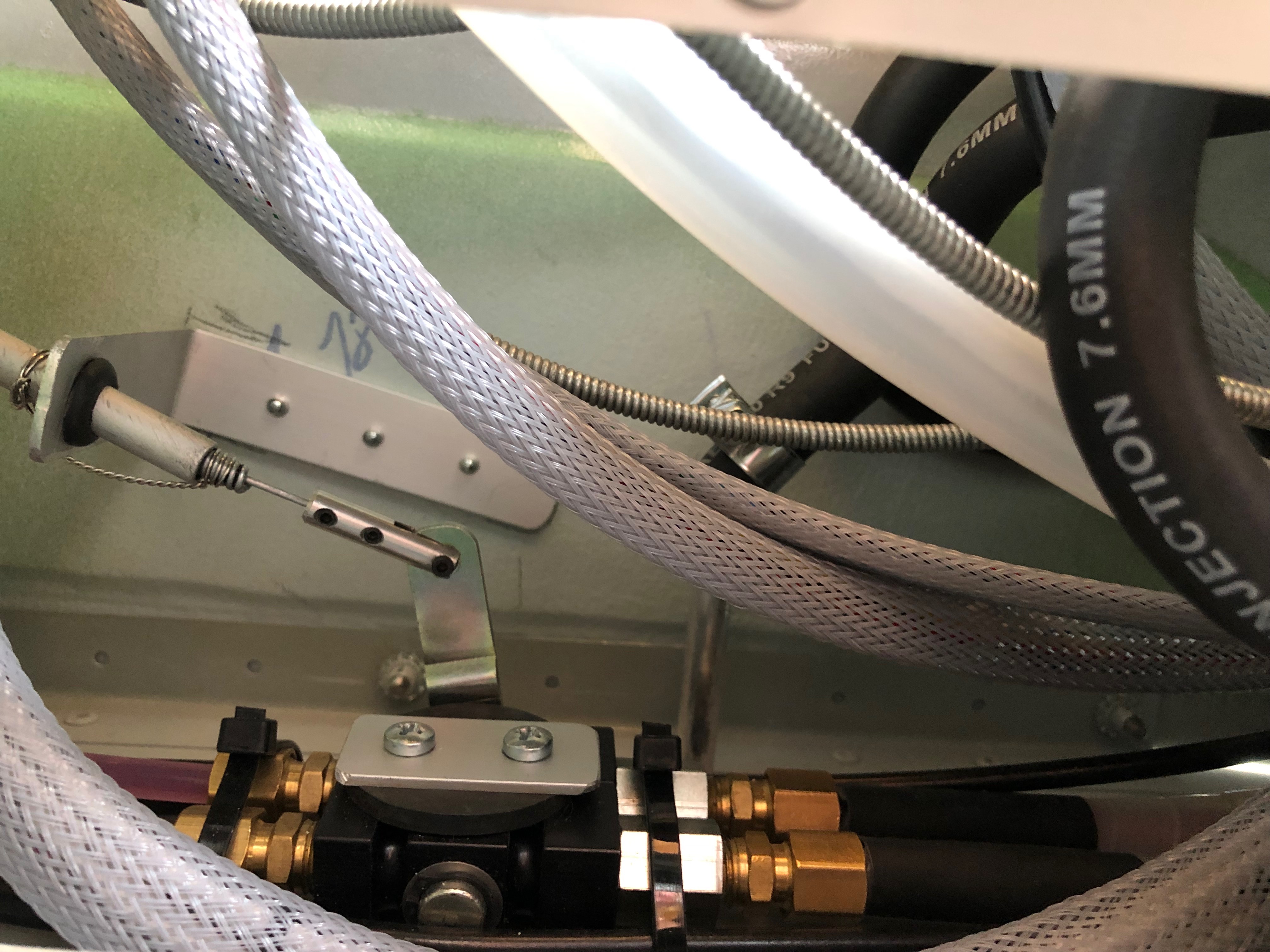
Now the transducer is mounted the fuel lines are run from the 4-way connector to the unit and the output line is run to the ‘T’. At each stage of the installation the fuel line is purged with fuel to ensure no debris is present that could block the fuel flow to and from the unit. Once the fuel hose is connected and secured with pipe clips, fire resistant sleeving is added and secured into place with wire lock.The 4-way and ‘T’ connectors can be positioned adjacent to each other allowing for a neater installation.And the fuel lines are covered with fire and heat resistant sleeving and wire locked into position.The finished installation with the fuel pressure switch just visible at the bottom of the photo.
So just enough time in the day to re-assemble everything before departing for Vienna leaving the wiring to the EMS and test runs for when I return. No rush to finish as the runway is still sopping wet at Maypole and there’s more rain to come!
Due to Maypole’s runway and taxiways being waterlogged, it’s not been possible to fly since before Christmas. I decided to use the time to do some more work on the plane. I had originally made the decision not to fit a fuel flow transducer but after flying the aircraft a few times I realised that the addition of a transducer would help me understand how much fuel I’m using more accurately than I have been using a spreadsheet. It would also help me on some of the longer flights allowing me to balance fuel use against speed.
So on the 4th Feb I talked to the LAA and asked what was the best approach to carry out the mod. I didn’t want to start the mod only to wait ages for the approval to come through. They said that the best thing to do is send the paperwork in and await their approval as it could take a while to be approved. To my surprise I received an email from the LAA on Friday 28th to say that I could go ahead with the work.
First thing to do is make a bracket to mount the transducer on. I used a piece of aluminium angle which would be screwed to the firewall using M6 screws and thick rubber washers to absorb any vibration.The transducer requires 1/4 NPT 27TPI fittings to connect to the fuel pipes. These are sealed with Loctite 577.Part of me thought ‘if it ain’t broke don’t fix it’ but I think the work needed to fit the transducer will be worth it in the end. So it’s time to start removing parts… With the parts removed I can try different positions to check the fuel fuel pipe runs and clearances. Despite quite a bit of space on the firewall there are very few places the transducer can be mounted as it has to be mounted with the wires at the top and with straight runs of fuel pipe each side to reduce any turbulence in the fuel flow as this may cause erratic readings. The existing and proposed fuel feed schematic. Essentially the 3 way and 4 way connectors are swapped and the transducer is inserted in the line leading to the 2 carbs so only one transducer is required. Other installation options require two transducers, one on the feed and one on the return line but this is a much simpler method.In the ‘as built’ scheme, the 4 way connector takes the fuel from the mechanical pump, splits to the carbs either side and the forth connection is restricted and returns any unused fuel to the left tank. In the new scheme the outlet of the transducer is fed into the 3 way connector which supplies the carbs. The 4 way will be inserted in the line between the mechanical pump and the transducer. The third spur will be connected to the fuel pressure sender and the forth, which is restricted, will be connected to the return line to the tank.The mounted transducer with the fuel pipes connected but without the fire sleeving. Quite pleased with today’s progress but ran out of time so will hopefully finish the installation and wiring tomorrow and perhaps even carry out some test runs.
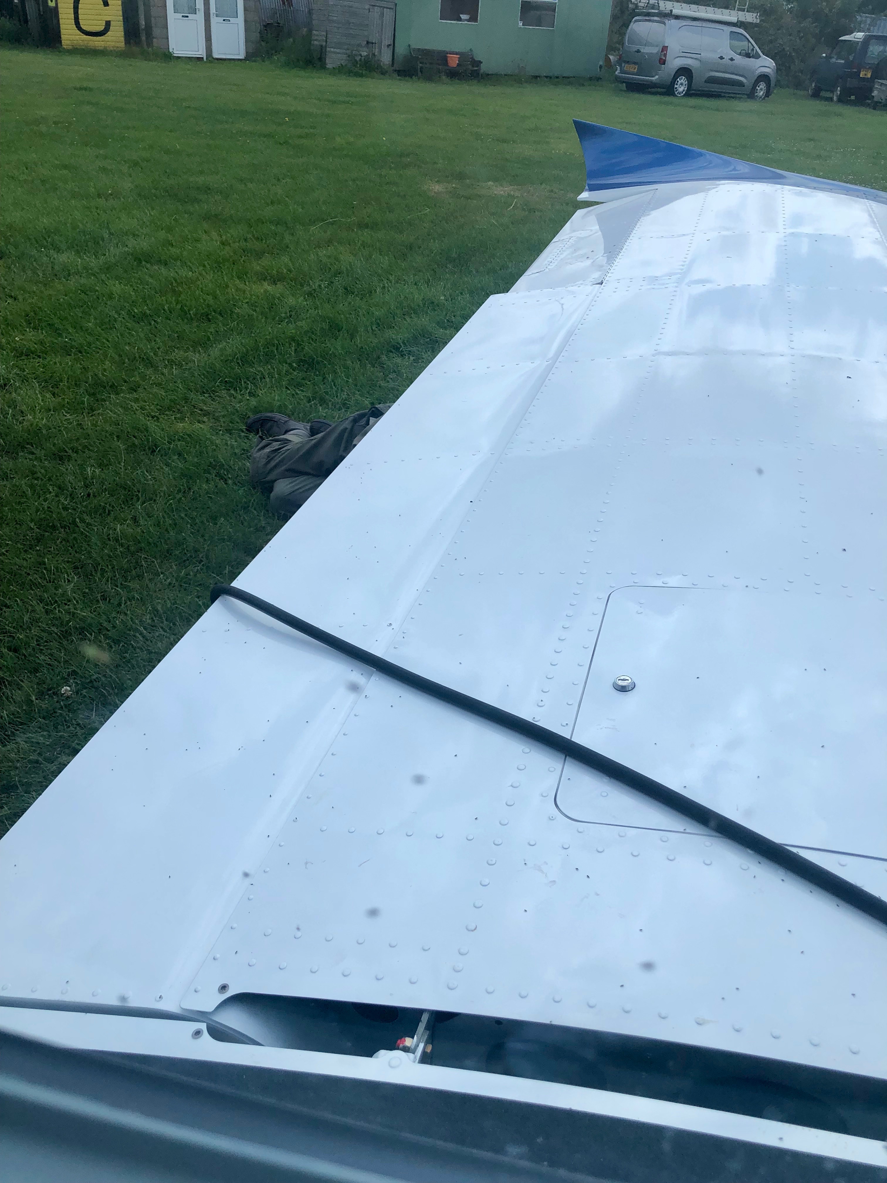
One of the jobs that I’ve not looked forward to is the fuel flow test. Not because it’s difficult or complicated but more that it seems dangerous. It involves taking a feed off of the carb line and running a long pipe away from the engine and prop. Several timed measurements take place using the electric pump on it’s own with the engine stopped, one with the engine running at full bore using just the mechanical pump and one with the mechanical and electric pumps working together. The aircraft has to be choked and Ian offered to do the work outside the cockpit. We used radios to signal the start and stop of each engine run.
The run off from the carb fuel line using a ‘Tee’Ian hiding under the wing carrying out the fuel & time measurements. For the electric pump only run the amount that needs to flow is 125% of the maximum litres per hour for the Rotax. For the measurements where the engine is running at full bore, 27 litres will be used by the engine before any excess is collected so the excess should be 25% of the maximum per hour fuel amount so were expecting 6.75 litres as a minimum.The T&Ps at full chat look ok and the fuel flow results are far in excess of what’s required. Poor Ian need a new set of ears now though!
Well the best laid plans as they say… however with the weight and balance carried out yesterday meant my downfall today. Everything needed to be on the aircraft for it to be weighed however I forgot to ask Ian and Pete to help me take the canopy off. So I arrived to realise that I couldn’t do any of the things I had planned for today as I couldn’t get into the cockpit 😦 Usually people come and go during the day but no one turned up until around 3! So a very short day today.
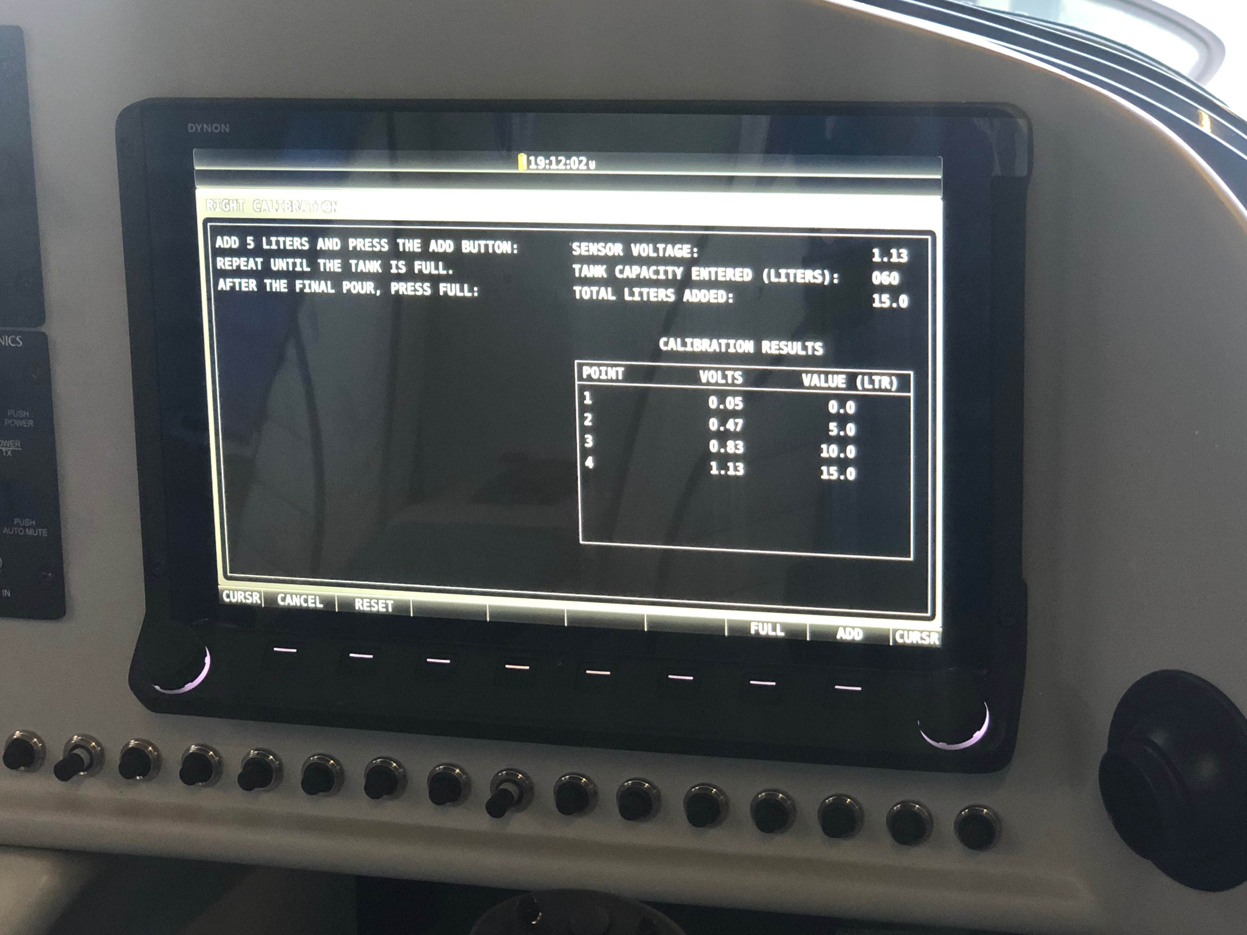
Up first was the calibration of the fuel tank sensors. This took longer than it should have done as I didn’t finish the process quite right on the first pass so needed to drain the tank and start again.
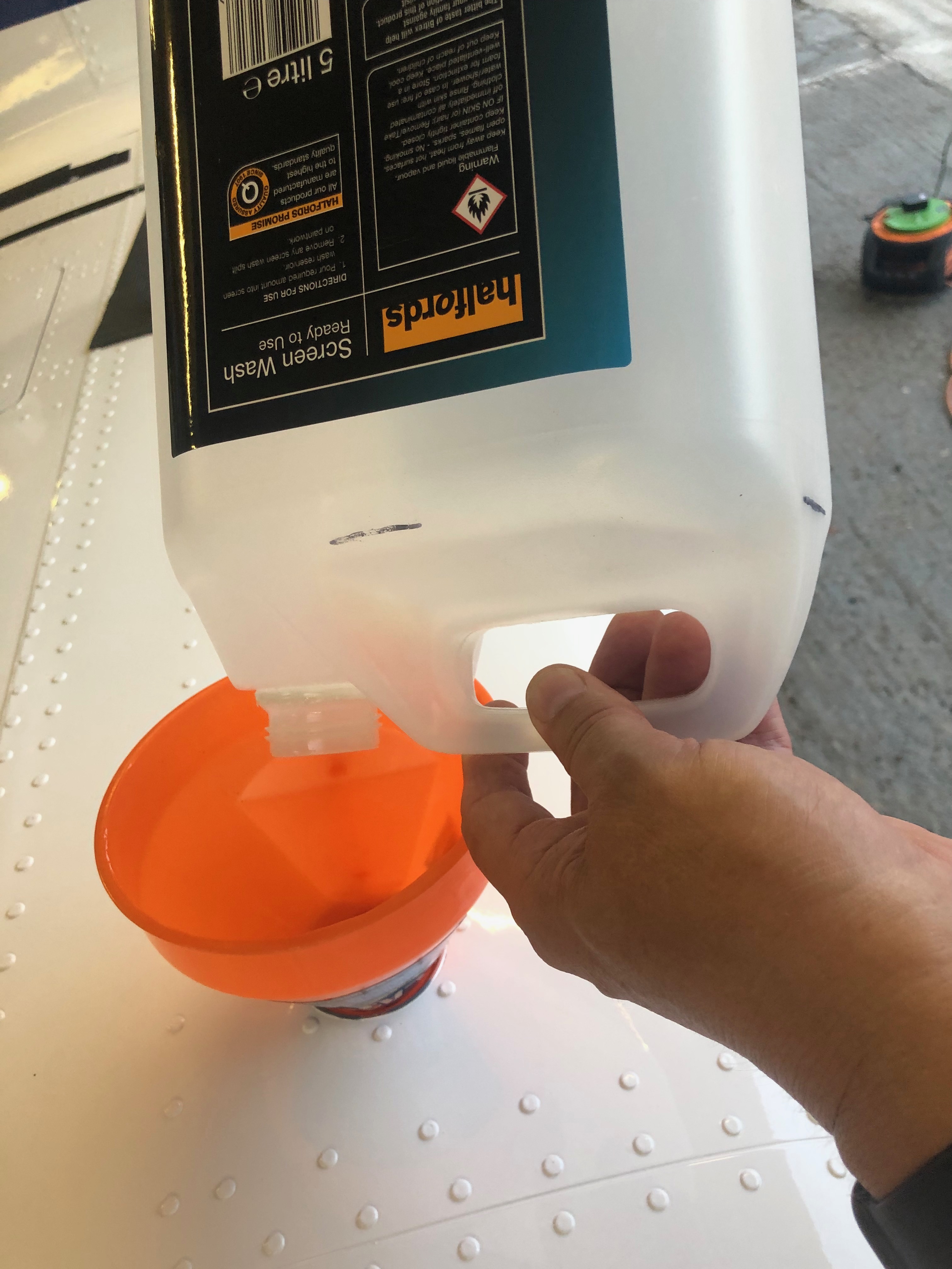
The calibration screen…I used a screen wash container that I had filled to the 5 litre mark and then filled that for each calibration point. The process was quite straightforward. Press start, pour in 5 litres of fuel, press ‘Add’ and repeat 12 times on the last fill press ‘Full’ except on the last fill you need to press ‘Add’ then press ‘Full’ Silly me got that wrong so…I had to drain out the tanks and start again! Eventually I finished it. The port wing will have to wait for tomorrow.
Short day today so just a couple of items. The first thing for today was setting the trim speed so it falls within the acceptable stop to stop time limits for the LAA followed by fitting the fuel pipe between the wing tanks and fuselage and finishing off by driving the holes for the LEMO plugs for the Bose headsets and fitting the rear trim panel. Also called CFS to see if my floats for the Rotax engine need changing as there has been a fault that’s been affecting them for 5 years now. You’d think they’d have sorted it out by now eh?
The starboard wing has a single pipe that runs from the fuel tank in the wing to the fuselage. It’s quite a tight fit so need to make sure it doesn’t kink and it’ll need protecting with some sheathing.The Port wing fuel tank has two pipes one for supply and one for return. When starting the engine it’s important to select the Port fuel tank as any surplus fuel is returned to that tank. If it’s already full it will overflow. Must make sure you don’t get the supply and return mixed up!The feed and return pipes from the fuselage. The bottom one is the return.I’ve already fitted the centre canopy release mechanism so all that is required is to drill and shape the two holes for the LEMO headset sockets. They fit from underneath so they can be fitted with the sockets already attached.Last job of the day is to fit the rear trim panel. I decided to make the panel removable so Rivnuts and screws are used to secure.
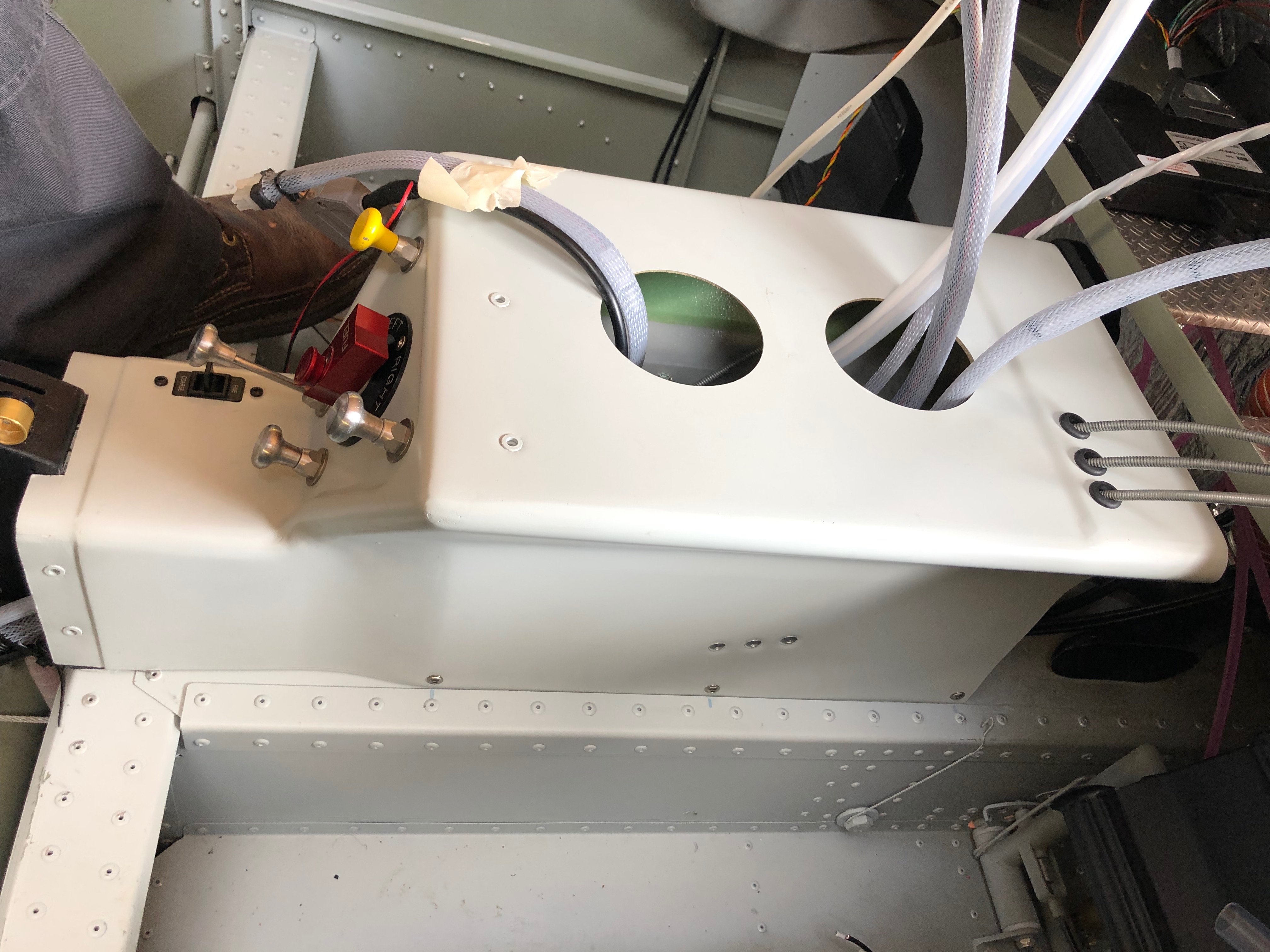
With all the prep to fit the centre console, today’s the day to fit it for the final time. All the control cable outers have been routed and cut, the connections worked out, the pipe runs decided on and checked. Now it’s just a case of carrying out the fit.
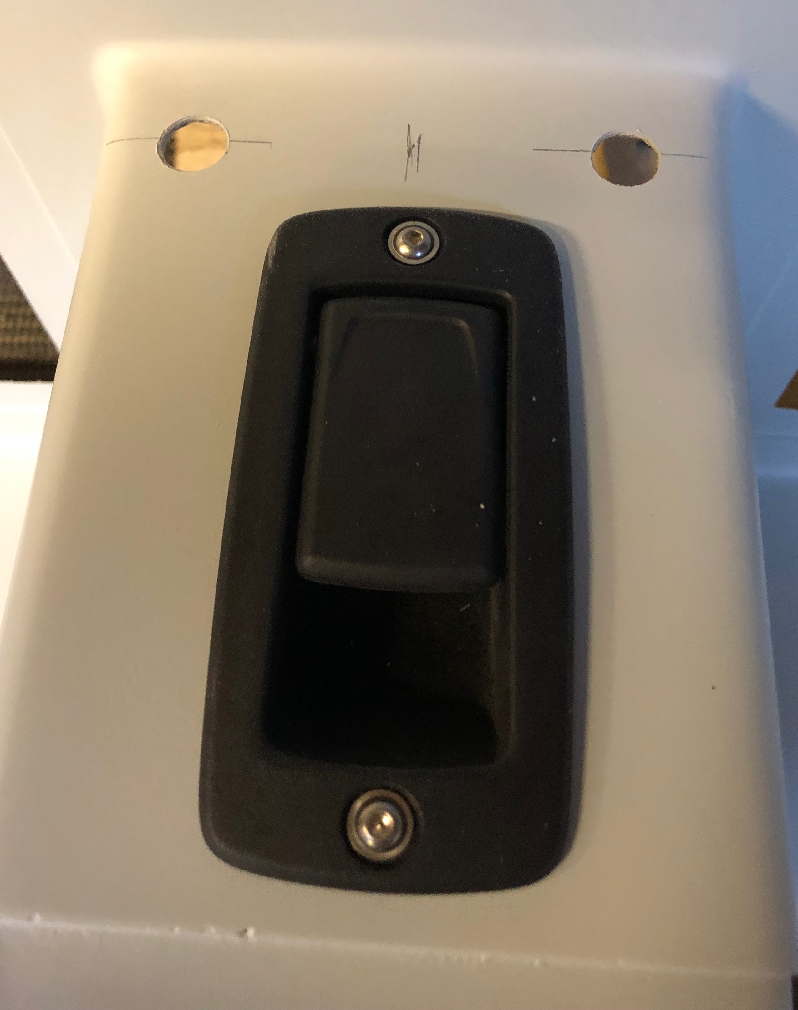
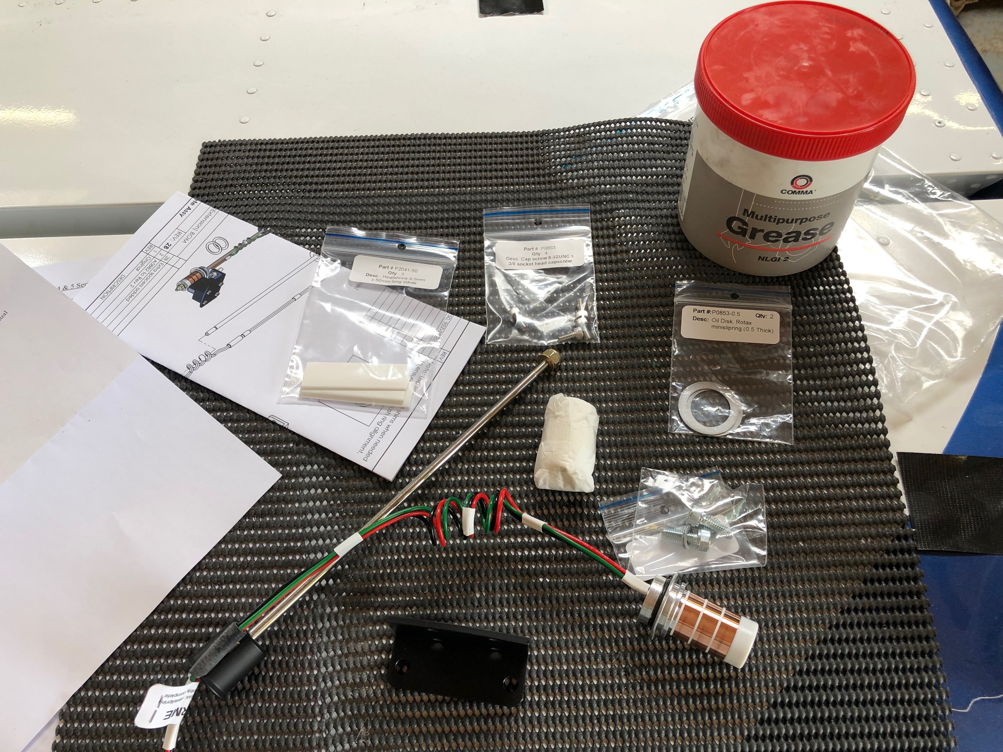
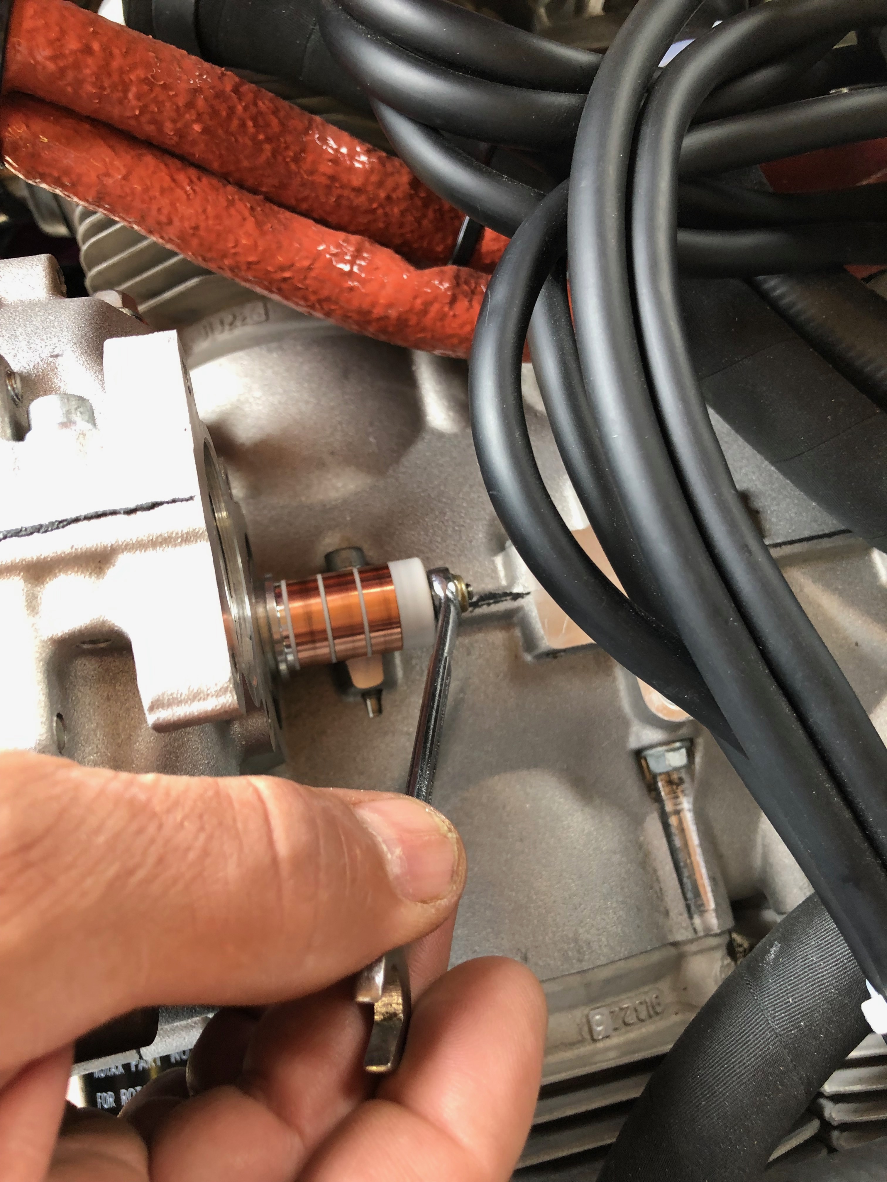
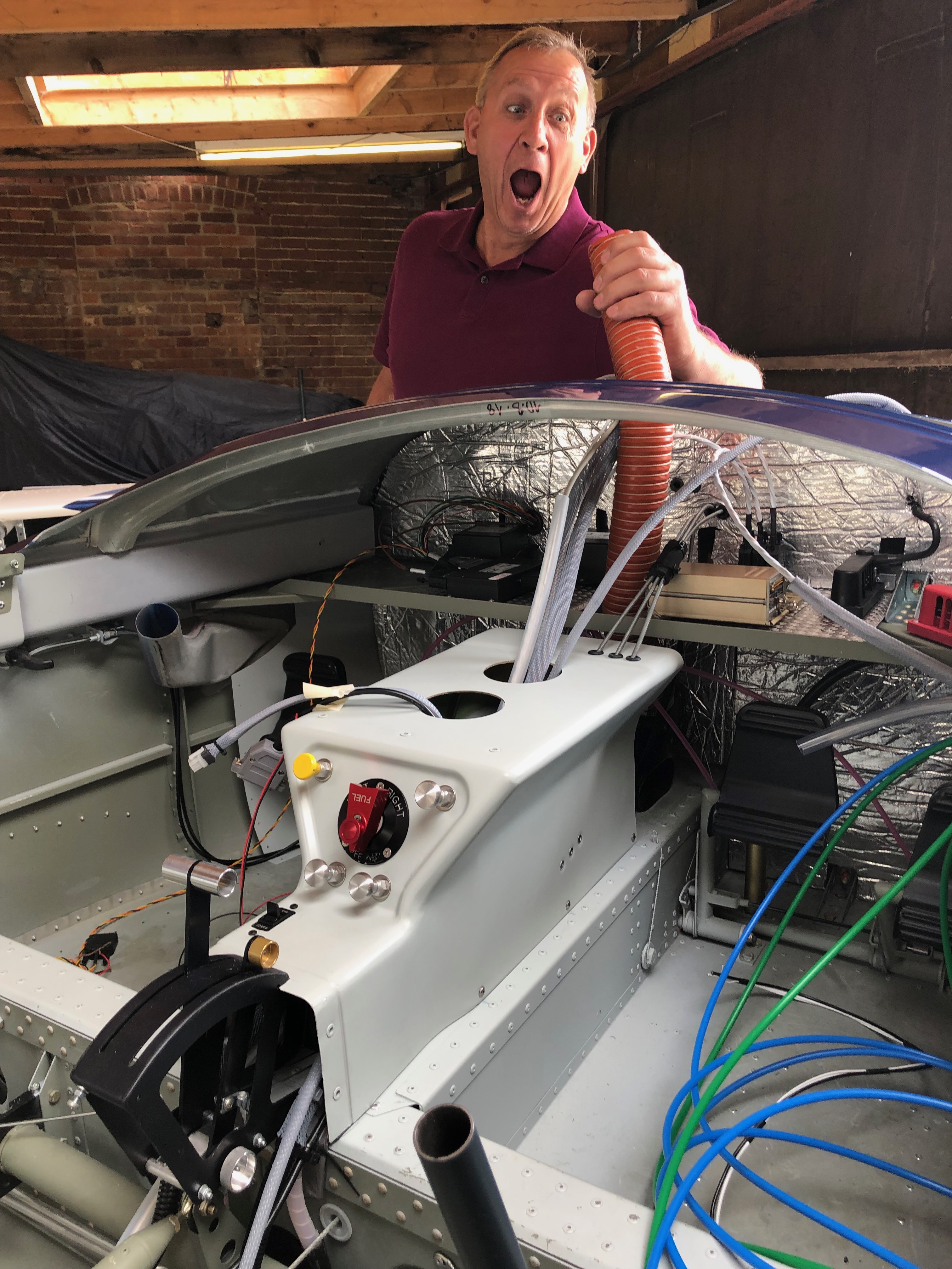
The fuel pipe from the selector to the tanks and engine need to be routed so they don’t kink and cut the supply whilst also being kept away from anything that may chaff them.This shows the support bracket for the park brake cable. It works well.The outer cables are wire locked to the adjusters so they can’t move once fitted.The demist control with the connector we made up. It looks a very good solution.At last the centre console’s complete with all the controls fitted, cables run and fuel pipes fitted. Having received the prop on Monday I can start to install the various bits. This is the mini slip ring available for Rotax 912ULS type 2 engines. It’s fitted to the rear of the gearbox.and then secured in place with a rod hat runs through the hollow gearbox shaft. The control wires spiral round the rod… and exit the front of the engine ready for connection to the pitch motor wires in the spinner.Once the slip ring is fitted the pick up bushes are installed. The bushes need run centrally on the slip ring. That’s all for the prop today, more tomorrow.Moving on to the panel again. I will fit as much as possible before fitting to the aircraft as it’s a lot easier than fitting the components when the instrument panel has been fitted to the aircraft. I’m not sure what Tom is doing here? Perhaps he’s going to start to sing? Captions please! He’s going home today so I’m solo again tomorrow!
Some time ago I had assembled the Andair fuel selector but hadn’t installed it as it wasn’t needed at the time. Today was the day to mount the selector and various controls into the centre console.
On a lot of centre consoles I’ve seen, the fuel selector and the flap control are positioned side by side in this recess. Personally I thought it would be better to keep the fuel away from any electrics, so have decided to mount the flap selector on the instrument panel.
The centre console which is made from glass fibre and re-enforced with carbon fibre panels. I marked the centres and positioned the selector where I thought it would look good.
After measuring and remeasuring the position to drill the mounting hole I used a step drill to cut a 26mm hole. It was only after doing this I found that Andair actually provide a template to help do this. Note to self: RTFM!
No problem with my measurements though and the selector cover goes on ok. I can now mark up where the Carb heat, Park Brake, Heater, and Screen De-mist controls go.
Although there are strengthening panels build in to the console I thought it would be good to further strengthen where the push/pull controls are mounted so made a couple of brackets…
and use a piece of glass fibre to secure them in place. This further supports fuel selector and controls.
This is what it looks like after the glass fibre has set.
Re-drill the holes
and the finished console ready for the the selector and controls to be mounted.
The cables are secured in place with nuts and I’ve put another washer on the back to spread the load even more. Taking no chances!
The inners are inserted to finish off. I will be able to mount the console and work out the runs for all the cables and make sure they work in the correct sense i.e. Pull for on, push for off.
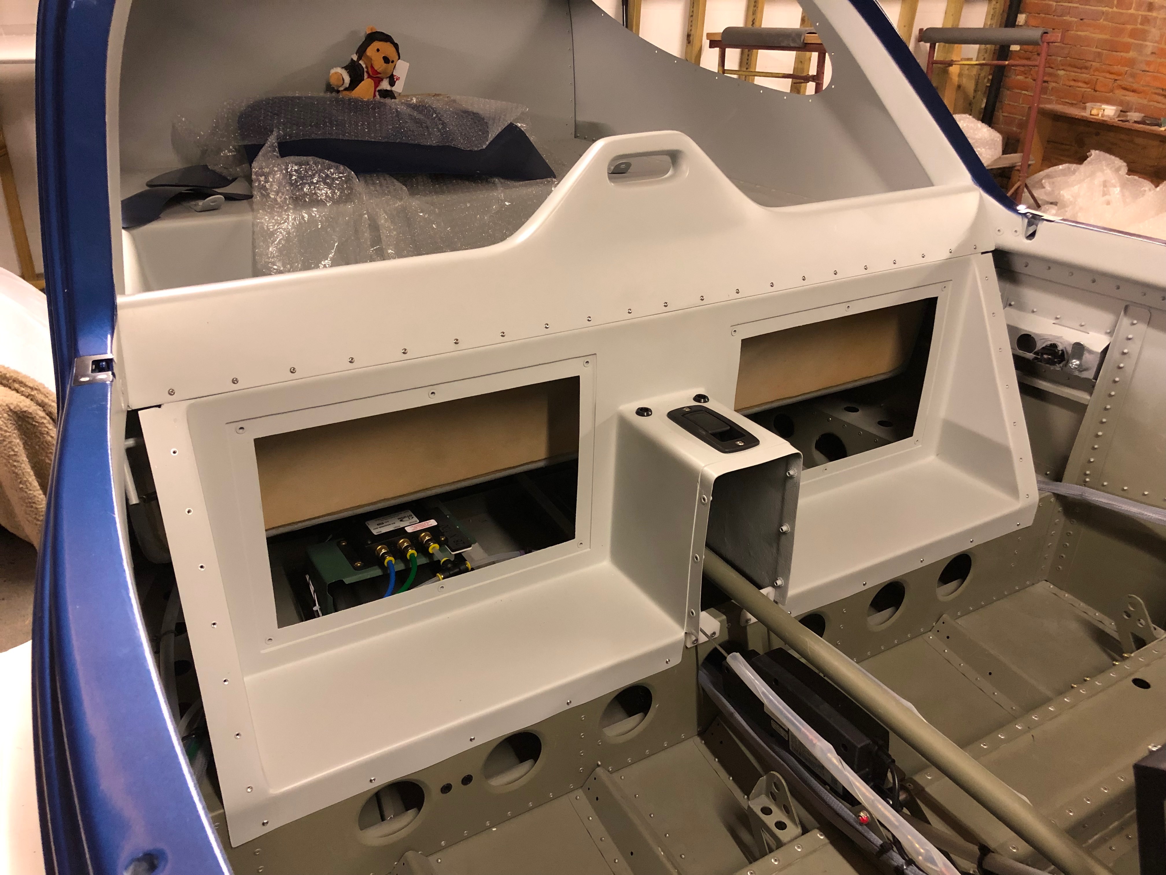
There are 2 brackets that secure the instrument panel and the centre of the panel is supported by the console.
The console and instrument panel temporarily installed to see how it looks/works. I can now prep for the install of the screens and various switches, circuit breakers and warning lights once I’ve completed my electrical design.
A number of jobs planned for today. Complete the engine NACA ducting, install the clevis pins to the carb heat control and cabin heater, install the fuel pressure sensor, install the engine intake air box, install the MAP sensor pipe, adjust and set the cowl quick release fasteners and install the control stick torque supports.
The fuel sensor and adapter were left to set with Loctite 577 overnight so can now be fitted to the fuel hose that I had added for it.
The hose is secured with a hose clamp and fire sleeve is added which is secured in place with locking wire.
The sensor is secured against movement and vibration with a stand-off.
These are the clevis fittings that are used on the carb heat, cabin heater, screen de-mist and park brake.
Now the sealant is set, the air box is mounted on a couple of brackets off the engine mount. It’s secured with a couple of Nyloc nuts underneath. Two short pieces of sturdy rubber hose are fitted over the carburettor inlets and the air box and provide a flexible joint between them.
They are secured in place with jubilee clips.
The SCAT ducting is secured in place with jubilee clips to the air box intake and the starboard lower cowl side NACA duct.
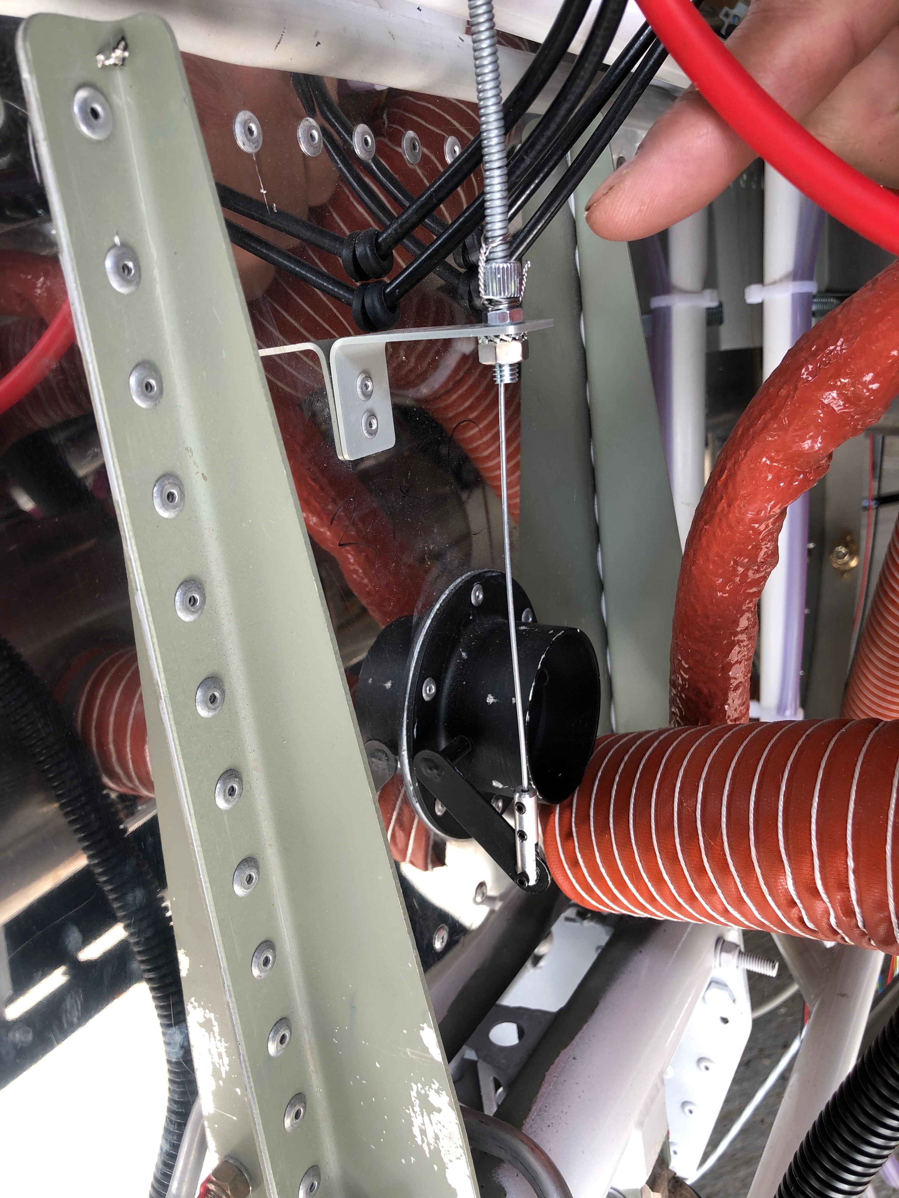
The ducting to the port NACA duct is run to the rear of the exhaust and then into the centre inlet on the heat exchanger, secured with jubilee clips and held in position with a couple of tie wraps.
Port NACA duct.
Even with all the space that the Bristell has It can get a bit tight with all the hoses that are required.
The MAP sensor has already been mounted so just needs a pipe to be run and of course some wiring at a later stage…
I’ve used 5.6mm ID R9 fuel hose between the carburettor balance pipe and the MAP sensor.
The quick release fittings on the fuselage have been riveted in place and now require them to be adjusted and set. First thing is to screw them in…
until they are flush with the cowl.
Once adjusted the pin can be pulled that sets them into position.
They are released by a quarter turn of the Philips screw and the fitting stays set in place.
I still need to repeat the process for the top cowl and the oil inspection cover. Ian will be installing the fittings during next week. Unfortunately the rivets need to be ‘squeezed’ and I don’t have the tool to do it.
Now I’ve picked up the control stick torque arms I can start work on the control sticks.
The fittings need to be checked and secured although they will need to be adjusted when the wings are fitted to centralise them, set the limit screws and check aileron deflection are correct.
The torque arm is attached at one end using the bolt from the control stick bearing.
The other end is secured with a 4 x 15mm rivet.
Both torque support arms fitted, completing a fairly productive day.
I’m still not 100% sure on the layout of the screens and associated control panels so I thought it would be good to add the pilot seat so I could check different layouts.
Once the seats were installed I could sit in the aircraft as I would normally fly it. The panel here has most of the bits I need but is missing the flap switch, some warning lights and the air vents.
I’ve stuck the pictures on using glue dots that allow me to move the pictures about. I can then do a ‘touch’ test on the layout to see what works best.
Monday was set aside to travel to Chilsford Farm to collect some of the outstanding items from the kit. So today I could get on with a lot of jobs that had stalled because of the shortages.
On Friday I sealed the canopy perspex with silicone and left it to set. The waste material was removed with a plastic scraper.
And cleaned off with some methylated spirits.
The result is good but not perfect in a couple of places so will need some attention once the canopy is mounted.
Next up is to connect the NACA ducts to the various intakes on the carburettor and cabin heater.
The SCAT ducting for the air intake is secured with a jubilee clip onto the air intake.
The ducting is cut to size and attached to the rear of the righthand NACA inlet on the lower canopy.
The heat exchanger is positioned and secured in place with large jubilee clips.
A short piece of ducting is installed between the heat heat exchanger and the heater intake that runs through the firewall to provide cabin heat and a de-mist facility.
A long pice of ducting is connected to the heater control and will eventually connect to the glare shield that includes the de-mist vents.
The lefthand side ducting runs from the NACA inlet to the middle heat exchanger connection but it’s quite tight so it must be routed so it doesn’t come into contact with the exhaust system.
View from the righthand side.
A spring is cut and installed to ensure that the air intake is supplied from the cold air vent by default.
One of the items I picked up on Monday was the pitot mount. I’ve already taken delivery of the avionics so I can mount the pitot onto the mount.
Instead of drilling holes and using screws I’ve decided to secure the probe into position with silicone which will provide a neat solution.
Once filled with silicone it’s left to set overnight.
The carburettor air box has two ‘horns’ that the SCAT hose connects to. They require sealing with heat resistant silicone and secured with three rivets.
The finished air box which will be left to set overnight.
The cabin air vents are supplied with fresh air from NACA ducts in the side of the fuselage. They require installing in the instrument panel and then connecting up with some scat hose. So a temporary fit of the panel is required to get the hose length.
Two brackets are clecoed into position and the panel is secure by two screws each side.
With the panel installed it give me an idea of the space I have for the avionics and possible positioning. Tomorrow I will fit the air vents and hose.
One job left over from installing the fuel system is to fit the fuel pressure sensor. The sensor cannot be connected directly to the hose. A 1/8″ NPT female to 6mm barb adapter is required.
As it will come into contact with fuel Loctite 577 is used to seal the thread before fitting.
The pressure sensor and adapter before being screwed together. They will be left overnight to set.
The final job for today was to trim the cowl to ensure is doesn’t come into contact withe the water radiator.
Following the build of my Bristell NG5 Kit No. 382 Registration G-MLSY