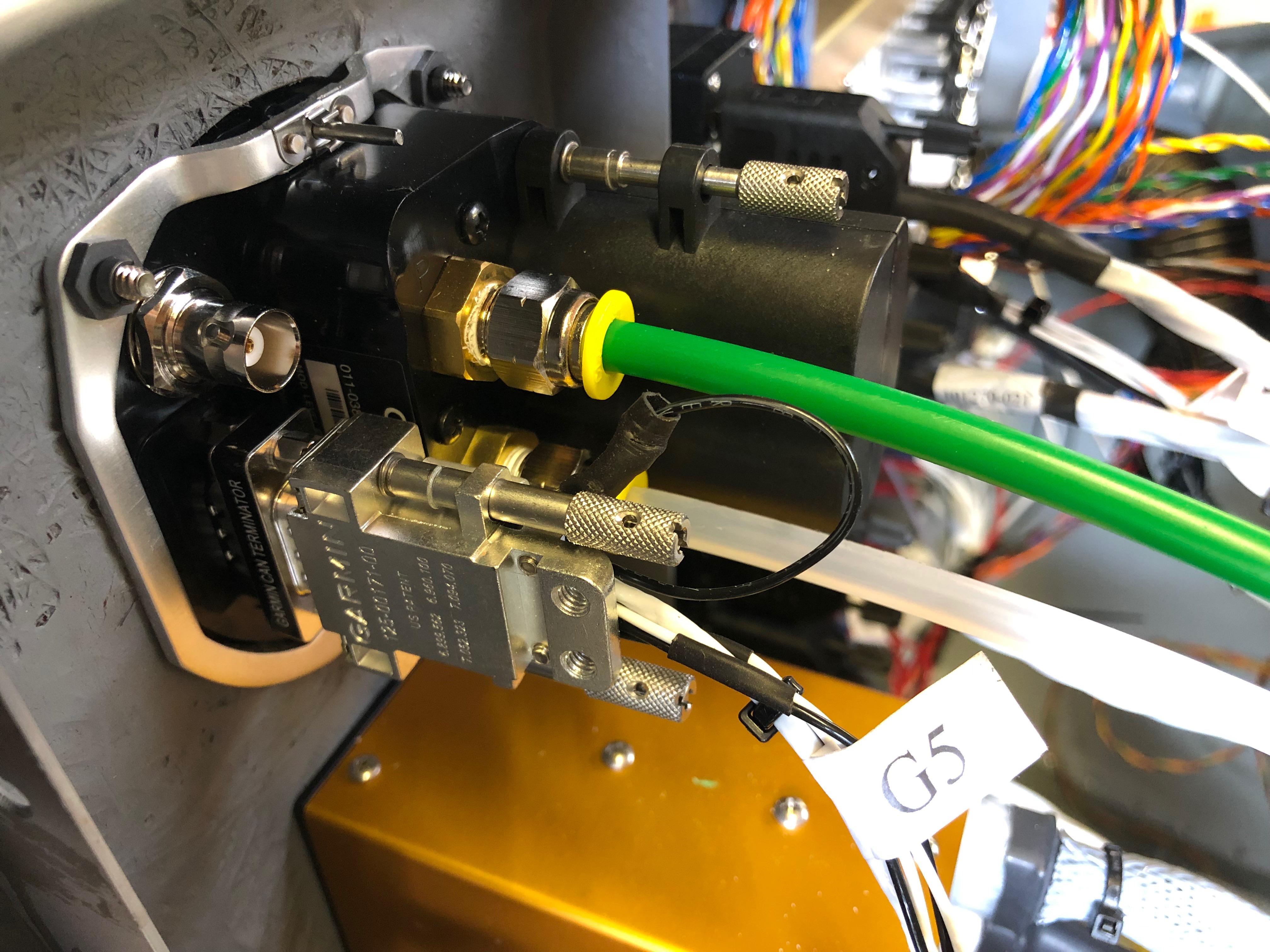
The wiring continues today with a couple of other items that I had put on the back burner. The tail strobe circuit was completed and wing strobe wiring started. One being the wiring of the extension wire for the elevator trim and the other the pressure plumbing for the G5.
After shimming the ADAHRS unit last night I replumbed the pressure system to make it tidier……allowing me complete the plumbing to the G5. I thought I’d start on the trim motor wiring but unfortunately DPD failed to deliver the wire I’d ordered so will do that another day! One of the jobs that I had been diverted from was the wiring up of the elevator trim so first thing is to solder them together and make sure that the colours match what I did for the aileron trim motor.
Music: The Pretenders – They were the support to Fleetwood Mac on Sunday at Wembley. I’d forgotten how good their music was!
Time for a short break from wiring but not for long before continuing the battle of the wires!
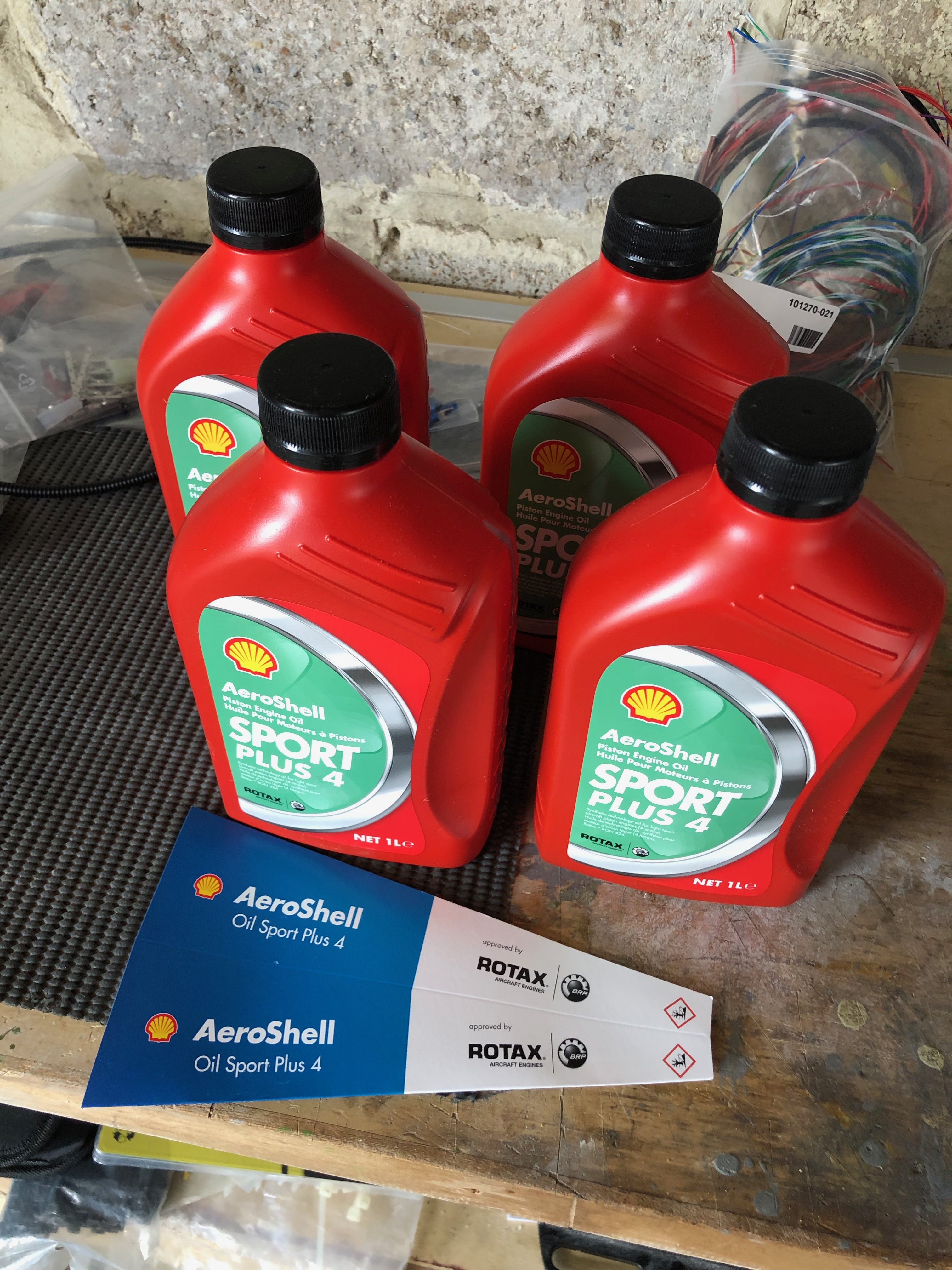
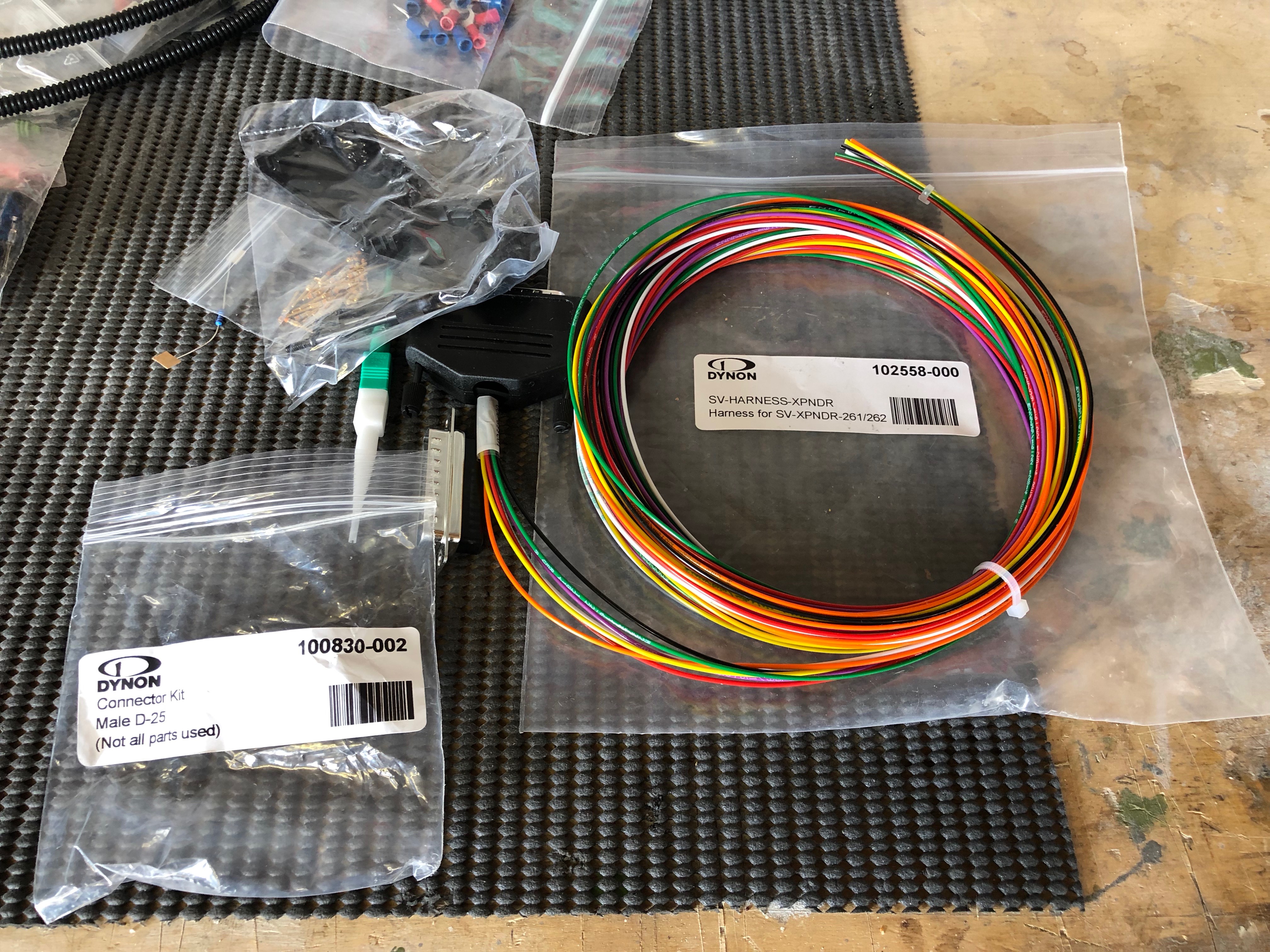
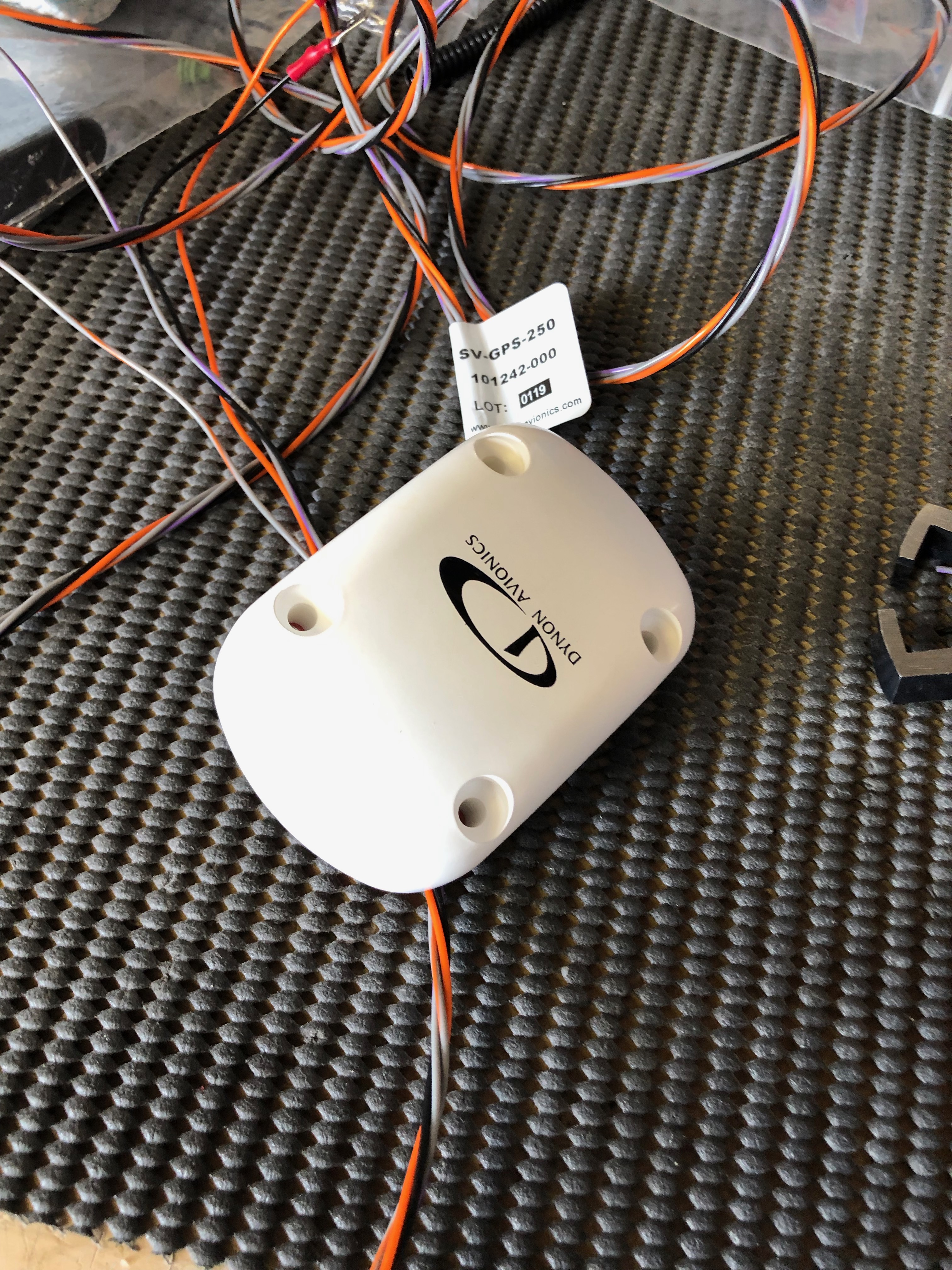
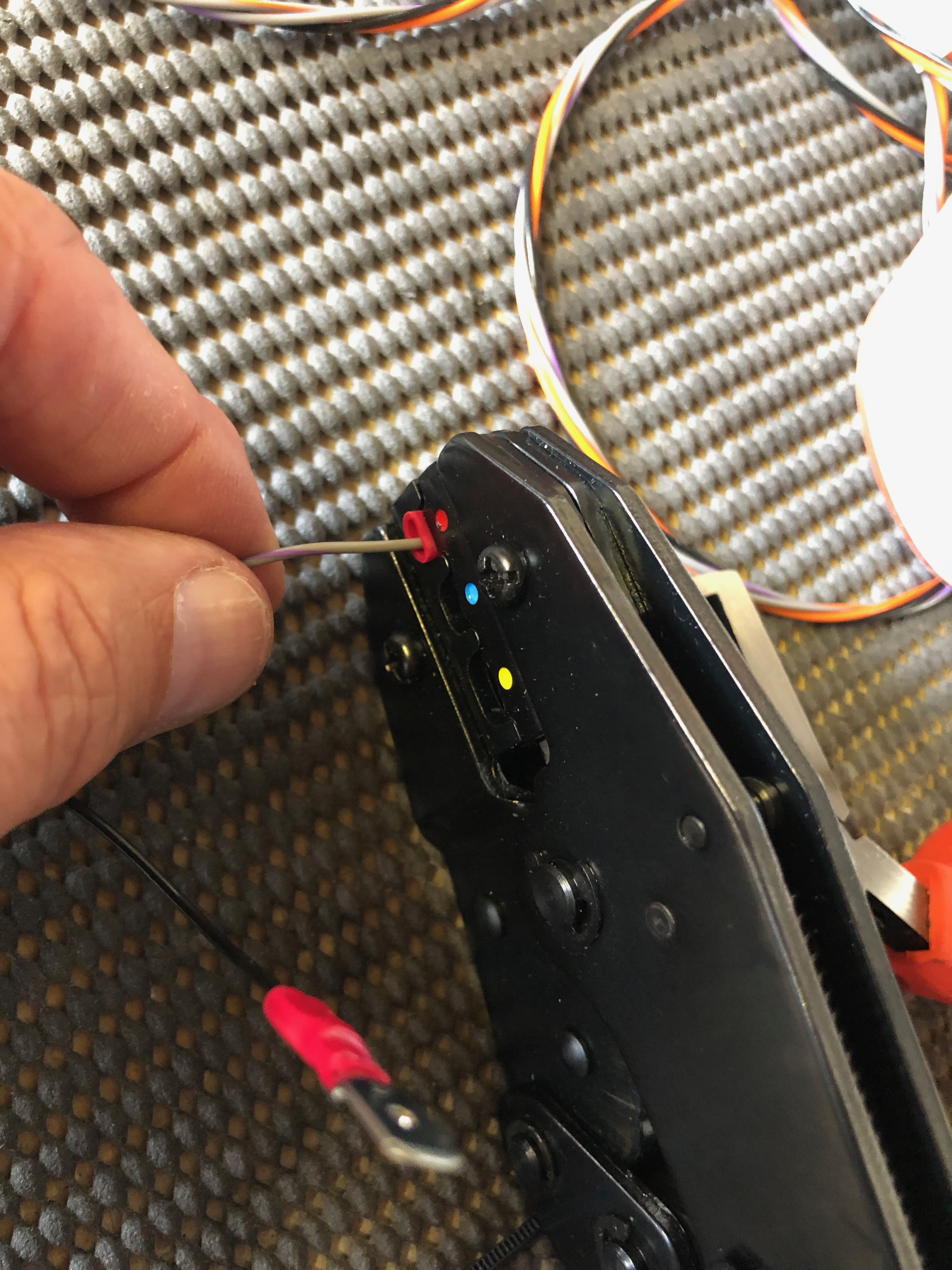
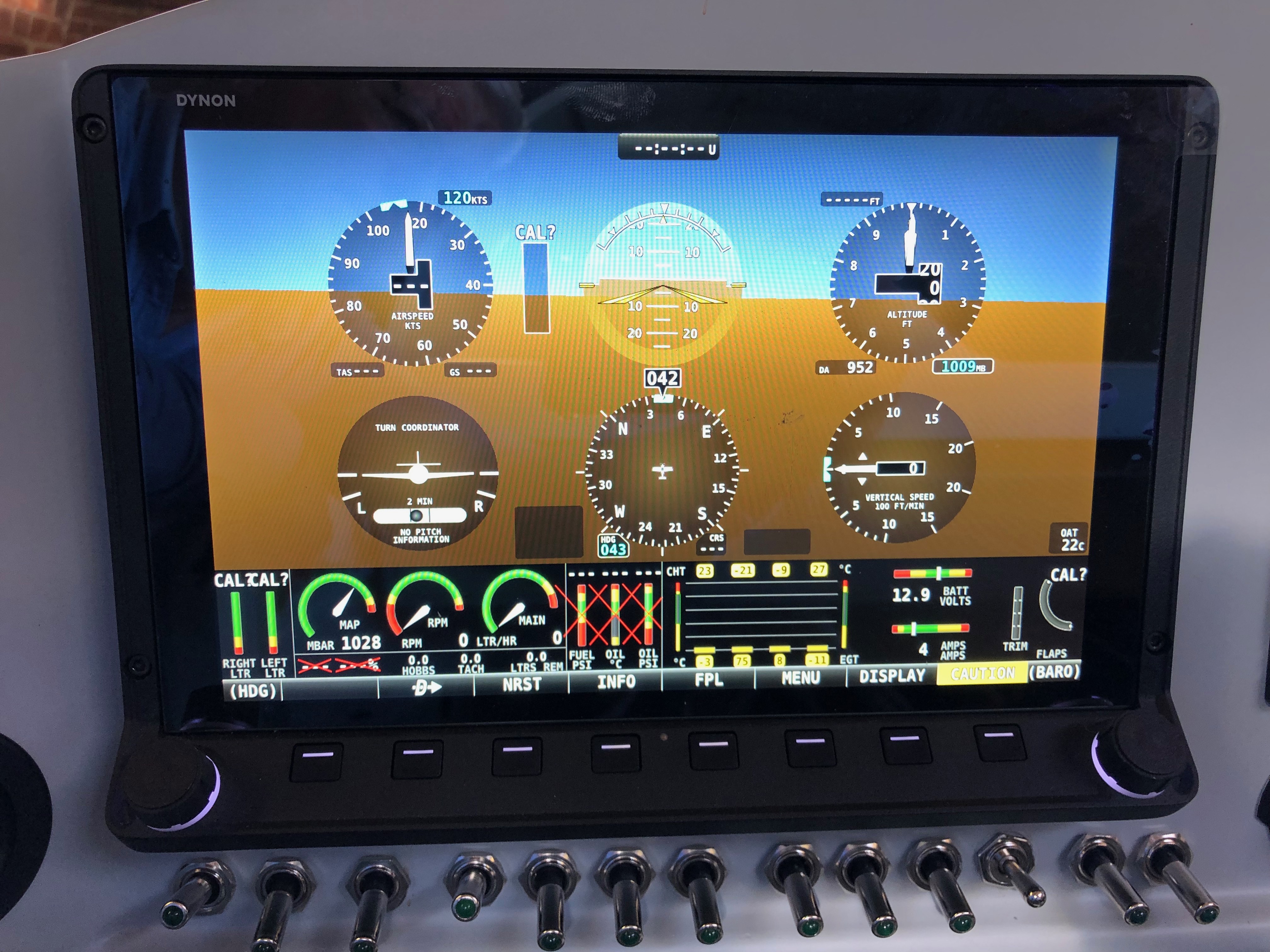
The Rotax engine comes with 4 litres of Aeroshell oil which I thought I’d add to the oil tank as a short break from wiring!I managed to get 3 litres in the tank but I will need to add more when the engine has been turned over a bit as there are a lot of empty oil pipes at the moment!After that very short break it’s back to wiring. This is the transponder loom which is a bit overkill for my needs. As you can see by the coil of wire there is a lot of unused wires but and a lot more has been trimmed from the length of the wires that are used! Once I had checked that it worked as expected I cut the unused wire off and covered the unterminated ends with heat shrink.Before adding a GPS receiver the SkyViews have no idea where they are in the UK, in fact they think they are in the USA! So I’ve taken the power and serial data leads from both SkyViews, spliced them and will connect them to the GPS. There’s a lot of cutting of wires and terminating them, mostly with fully insulated spade connectors using a special crimping tool.Once the GPS is connected a check is made on the connection to make sure it’s not reporting any errors and picking up satellite receivers ok..…and if by magic the SkyView now knows it’s in the UK! The system is reporting height and position correctly from my checks. If you look at the slip indicator you can see that its not in the middle and that’s because the ADAHRS isn’t quite level. There isn’t an adjustment that can be made to correct this so I’ll shim the unit.I’ve positioned the aircraft on a piece of level ground and I’ve shimmed the unit to make sure that it’s level and reporting correctly which it now is.
I decided to visit Air Expo at Booker yesterday but I can honestly say the show was a complete waste of my time. It was raining all day and a lot of the exhibitors had scaled down their stalls and some hadn’t turned up at all! I did buy a Sky Echo II there so I’ll see how that works when I finally get the plane flying.
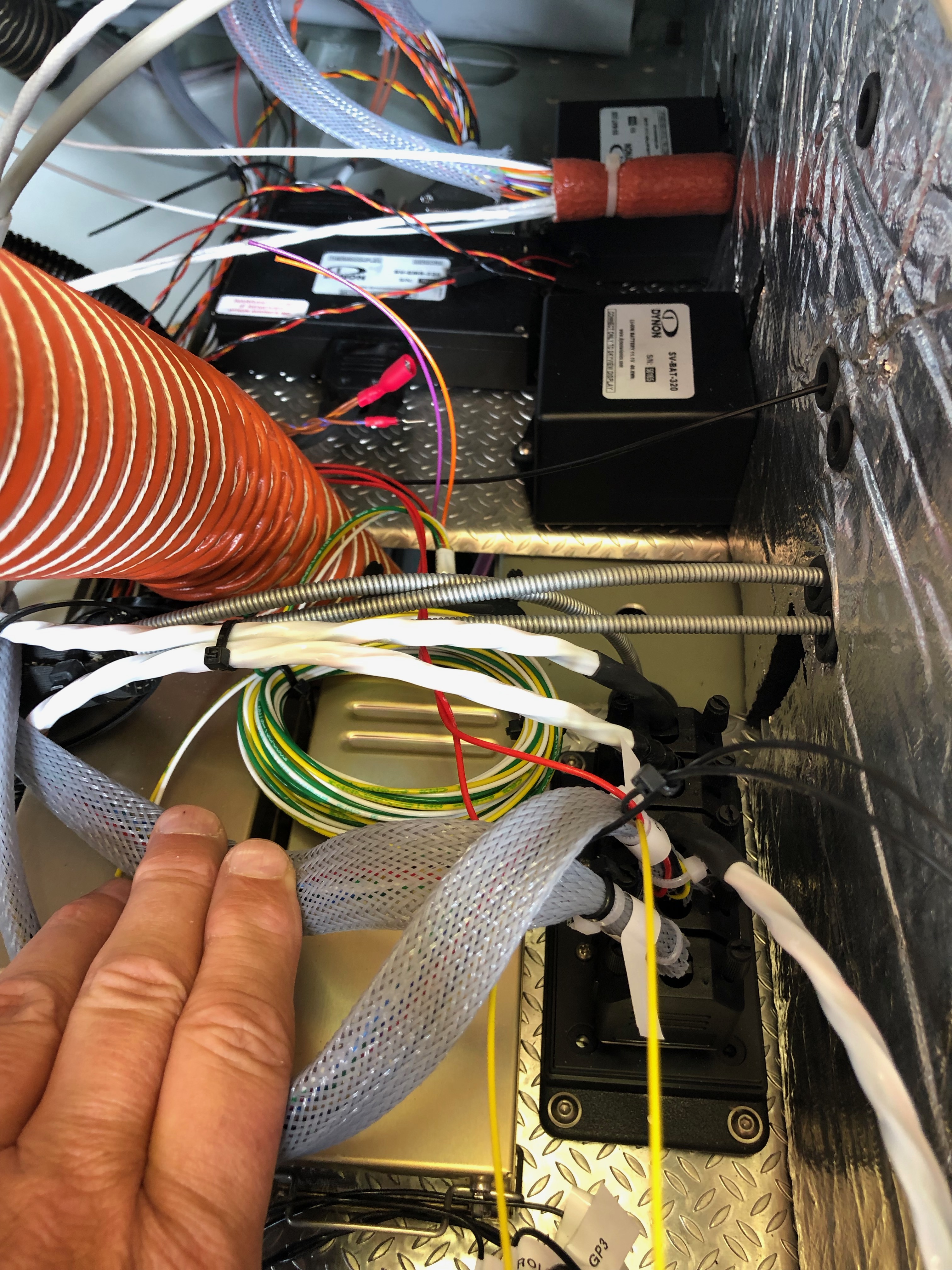
The aim for today was to continue the wiring and connect a few of the sensors.
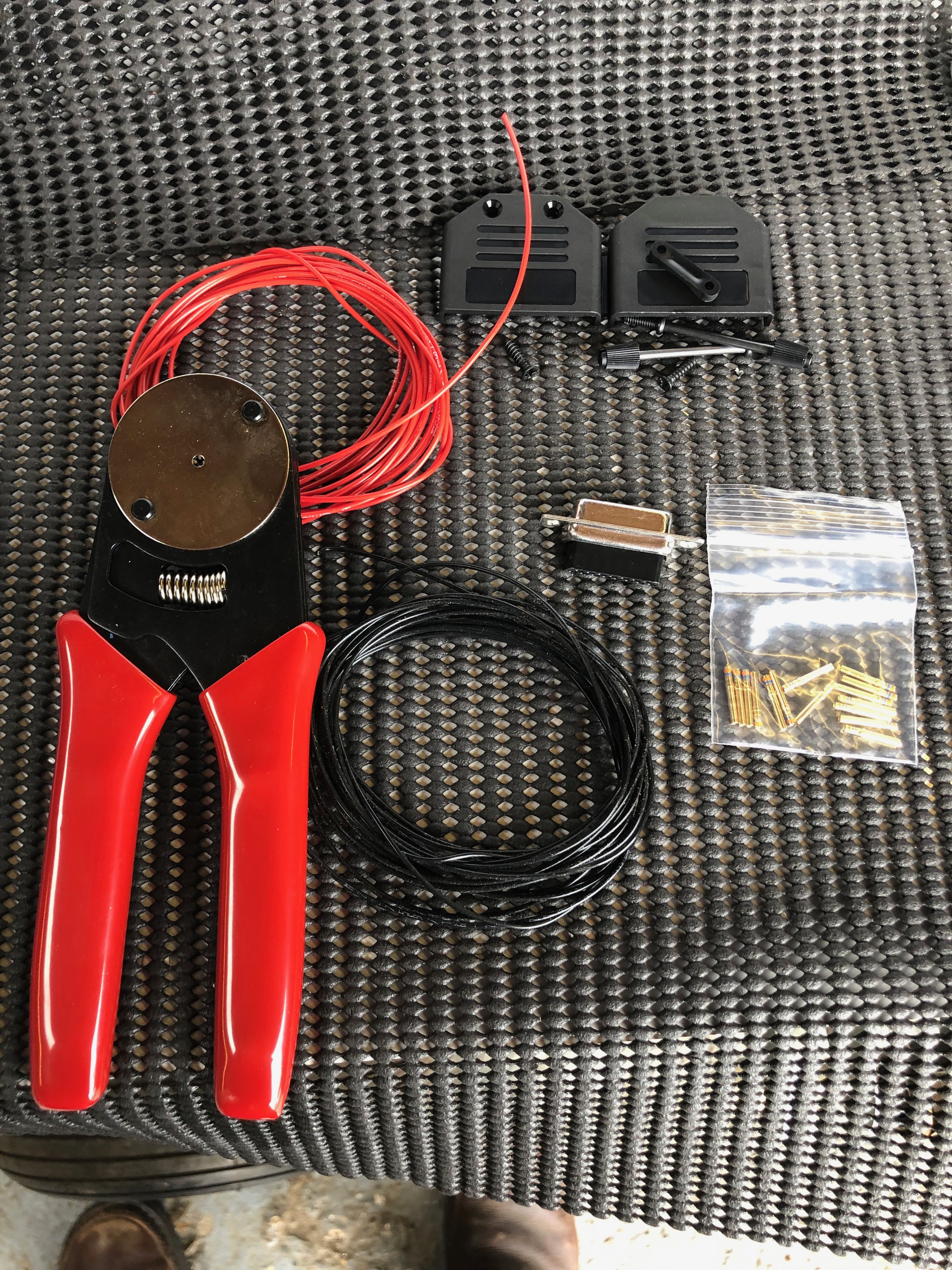
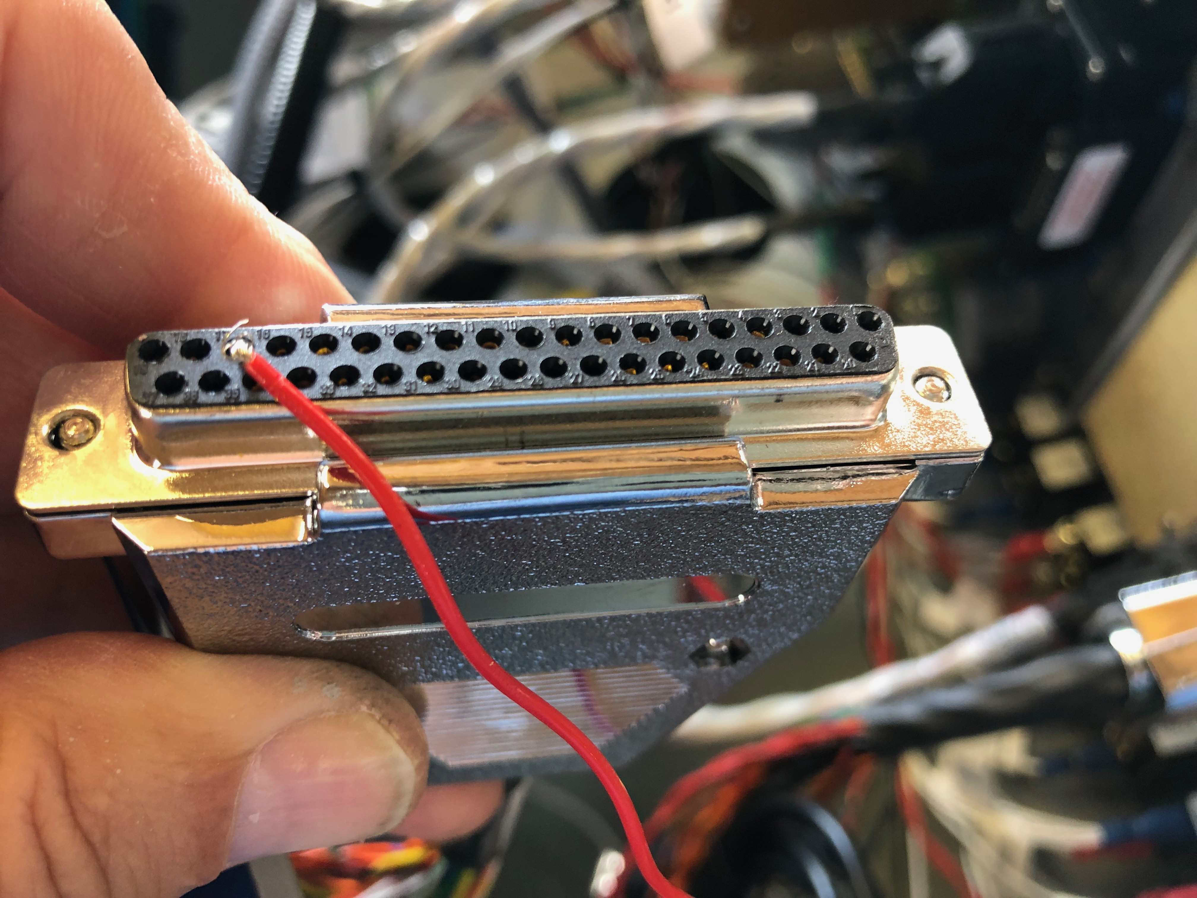
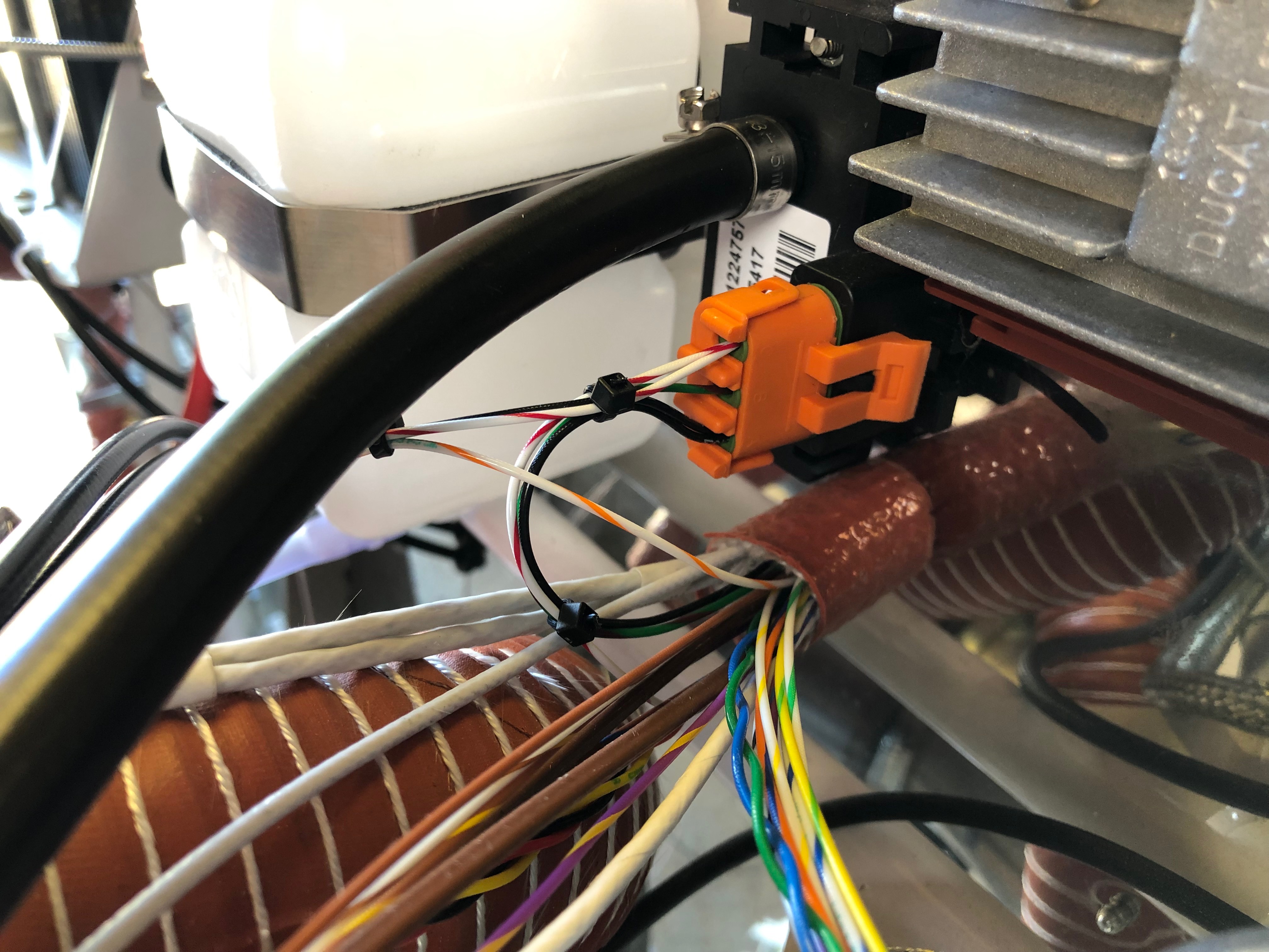
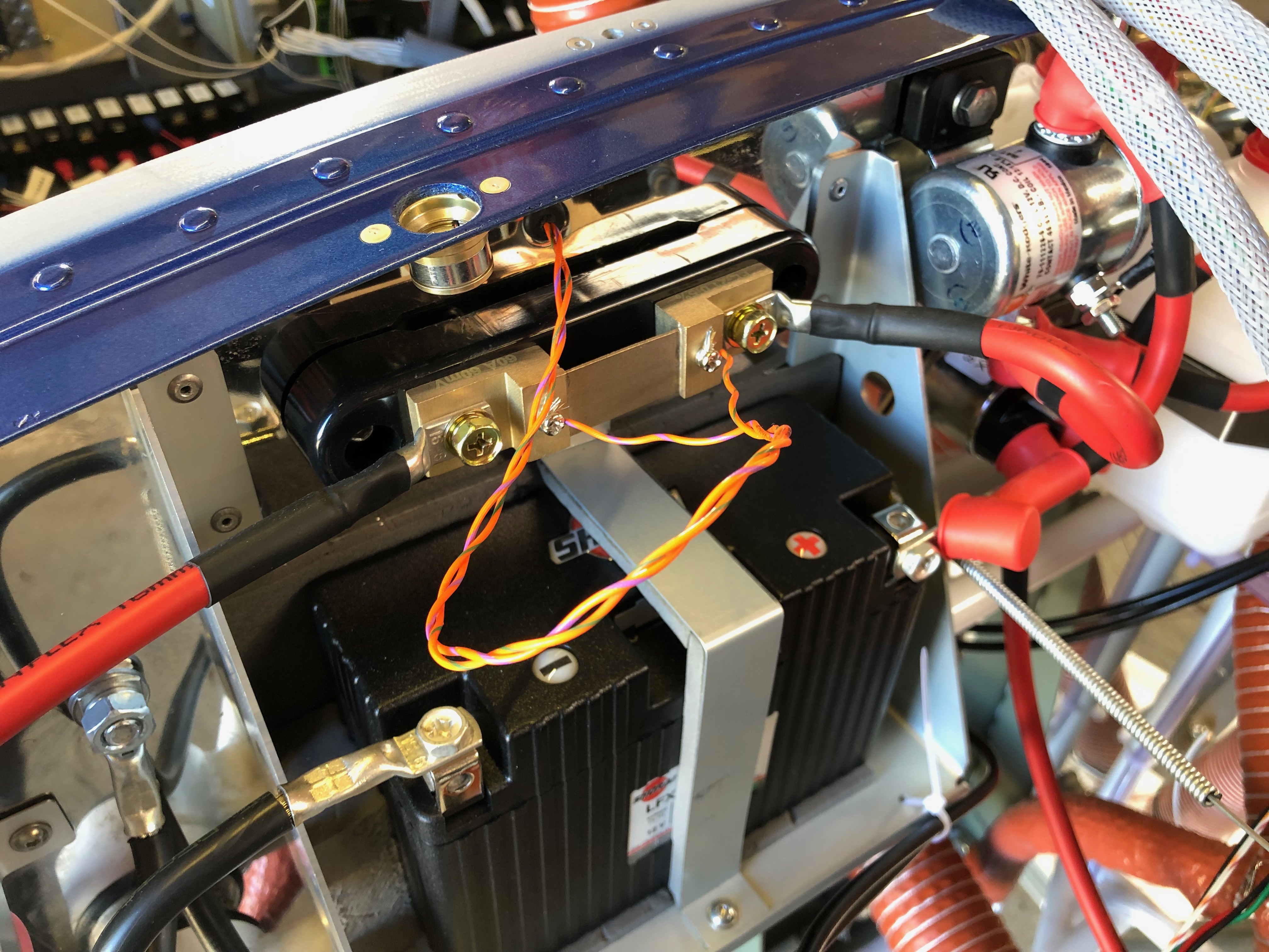
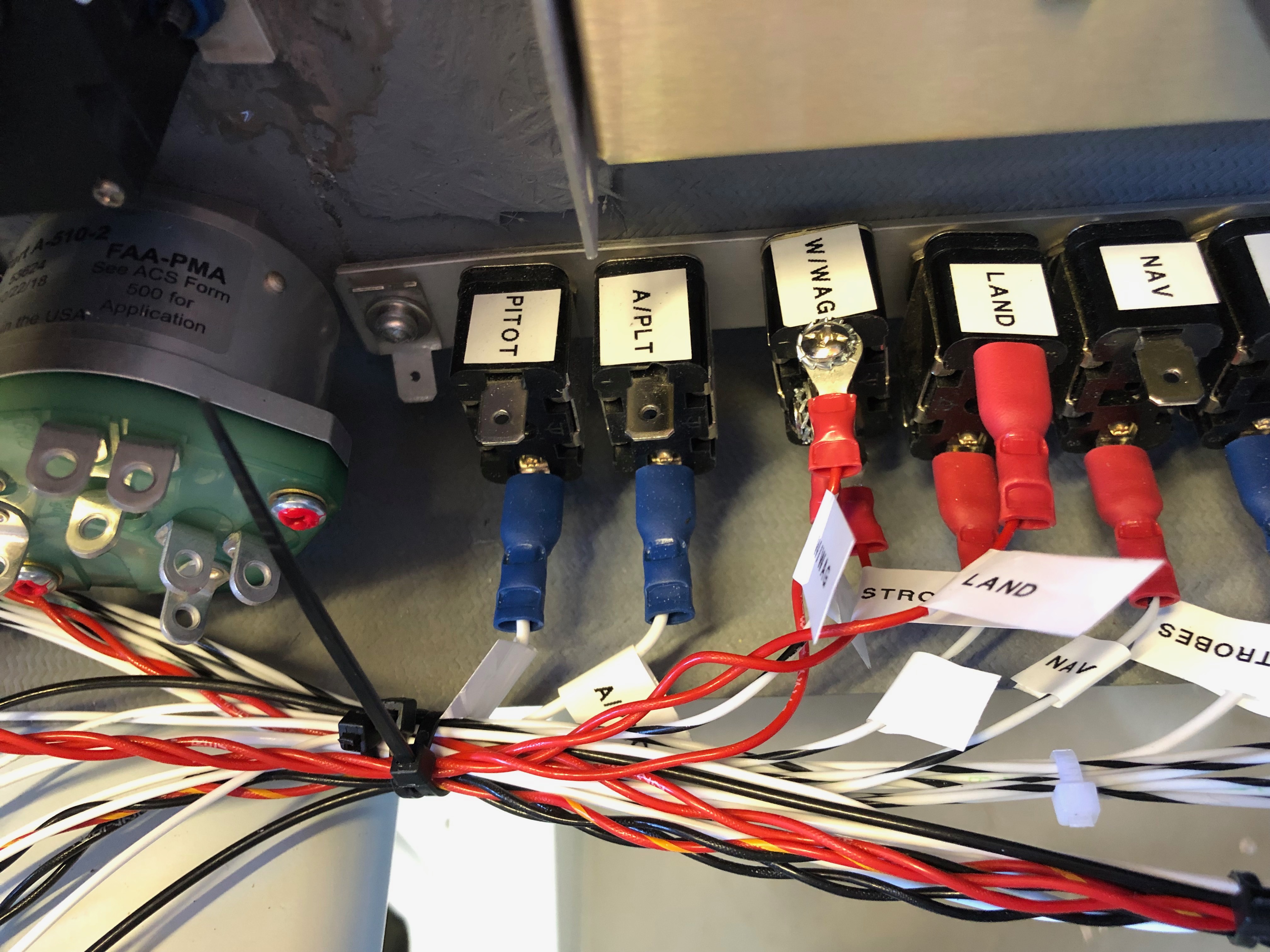
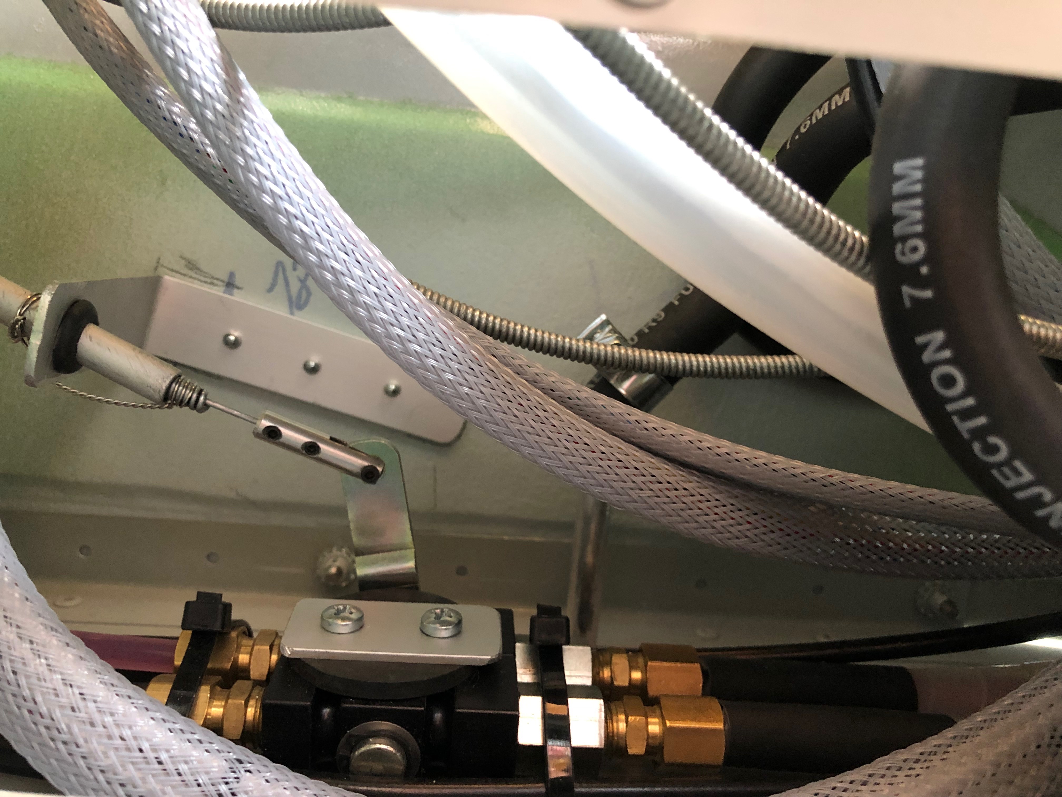
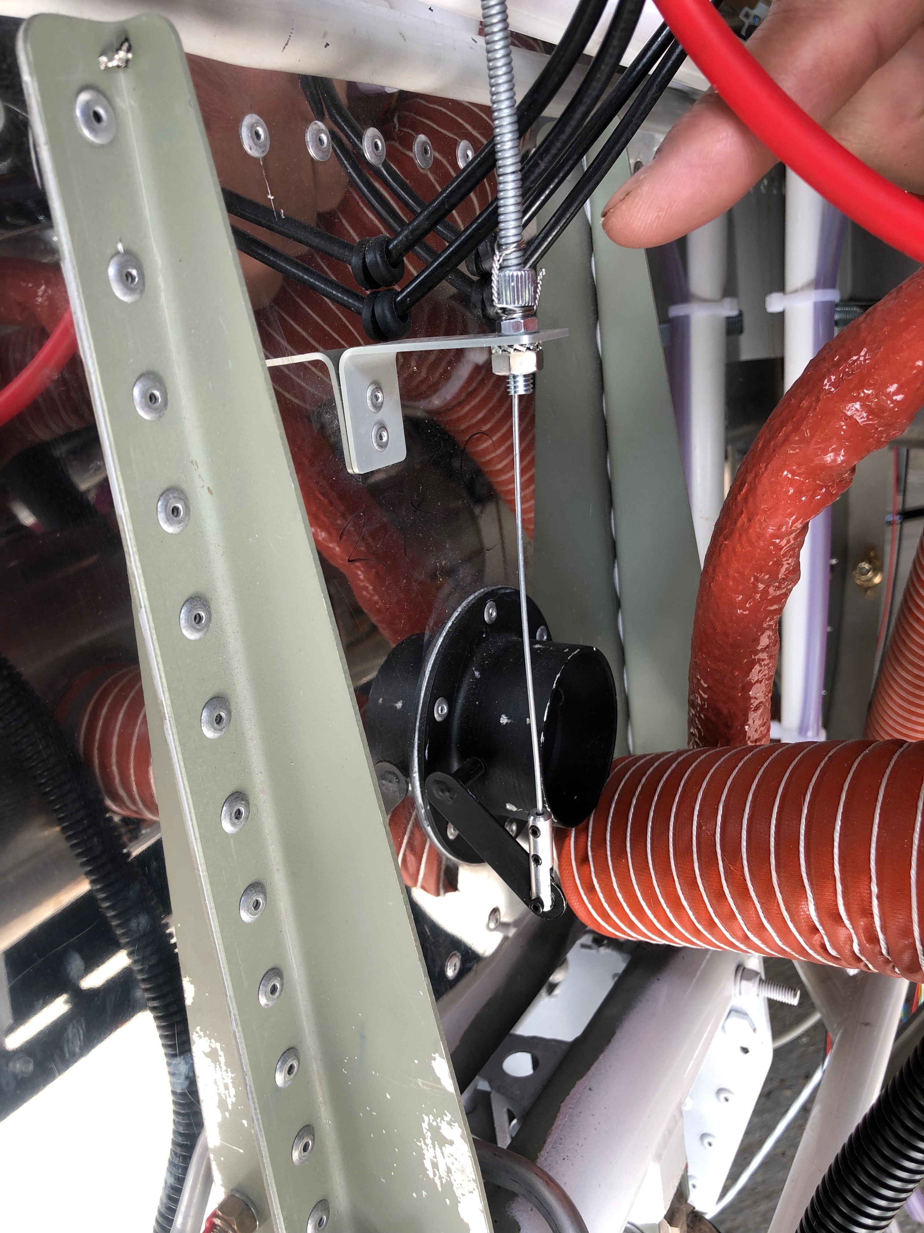
The EMS loom has a D37 that connects to all the various sensors around the aircraft. It’s good to check the pin out with a multimeter before connecting to any of the sensors. First up is the MAP sensor. The power and ground on this sensor can be shared with other sensors so I’ve broken out those pins to use for the the fuel pressure sensor.The system power load can be displayed on the SkyView by measuring the potential difference across a precise resistive load, in this case a Amp shunt. The wires connect to either side of the resister. To protect the SkyView from high currents a 1 amp fuse is connected inline which I’ve ordered and will be arriving Sunday so I’ll fit on Monday.The landing light controller that I bought from the States is wired up to a 3 position switch. I’ve designed the lights to be steady, wig wag and strobe. Hopefully it’ll work as designed.To get the light functions I need a 3 pole and 2 pole switch.The fuel pressure sensor is next but will be done on Monday now as I’ve run out of time.The HDX displaying in s ‘6 pack’ mode but you can see some of the sensors working correctly including the MAP, voltmeter and ammeter readings.
Dave came down to spend a day with me to see how the build is going so far and help me with fitting the prop hub and transponder aerial.
Forgot to attach the panel air vent ducting before I installed the panel. It’s a lot more fiddly i can tell you!Now I’ve received the drive lugs I ordered from CFS Aero I can attach the prop extension to the drive plate. The bolts to attach the extension to the drive plate are 8mm and the bolts to attache the prop back plate are AN5. So metric and imperial in the same installation – how ridiculous! The drive lugs are press fit and have a slight taper so the bolts are used to draw the lugs into the drive plate.The bolts have been lightly tightened before torquing up to 24NM.The mini slip ring control wires are adjusted so they hang just out the of the front of the prop extension.Heat shrink tubing is added to each wire and the hub offered up to allow the control wires to be connected.A heat gun is used to heat the heat shrink and the wires are pushed into the hollow shaft.Some Duralac is added to the lugs that enter the hub to ease disassembly and the bolts tightened.Time to check that I’ve got the measurements right for the prop extension so the engine cowlings are fixed in place.A good fit with an acceptable gap, so shouldn’t rub in service. I’ll fit the blades closer to finishing the plane to save them getting damaged.Next up is to install the transponder aerial. I’ve decided to mount it centrally between the main wheels. Still have to make up the coax for the radio and transponder but going to Air Expo on Thursday so will look to pick it up there.Dave checking out the pilots seat before leaving for home.So most of the main work has been completed so it’s time to start on the wiring. Not sure how long it’s going to take but need to make a tidy job of it and make sure that it’s easy to trace and maintain in the future.
With all the prep to fit the centre console, today’s the day to fit it for the final time. All the control cable outers have been routed and cut, the connections worked out, the pipe runs decided on and checked. Now it’s just a case of carrying out the fit.
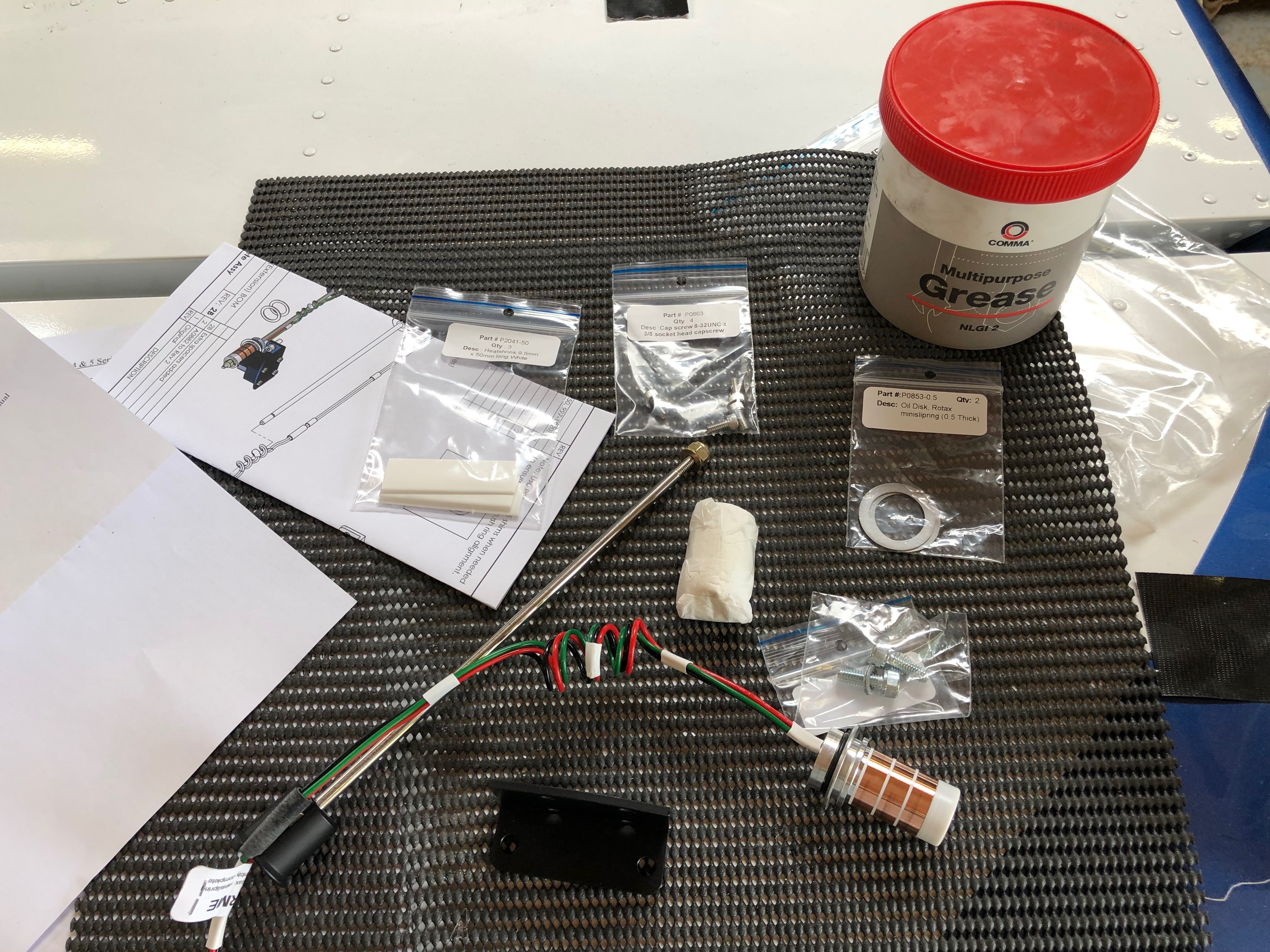
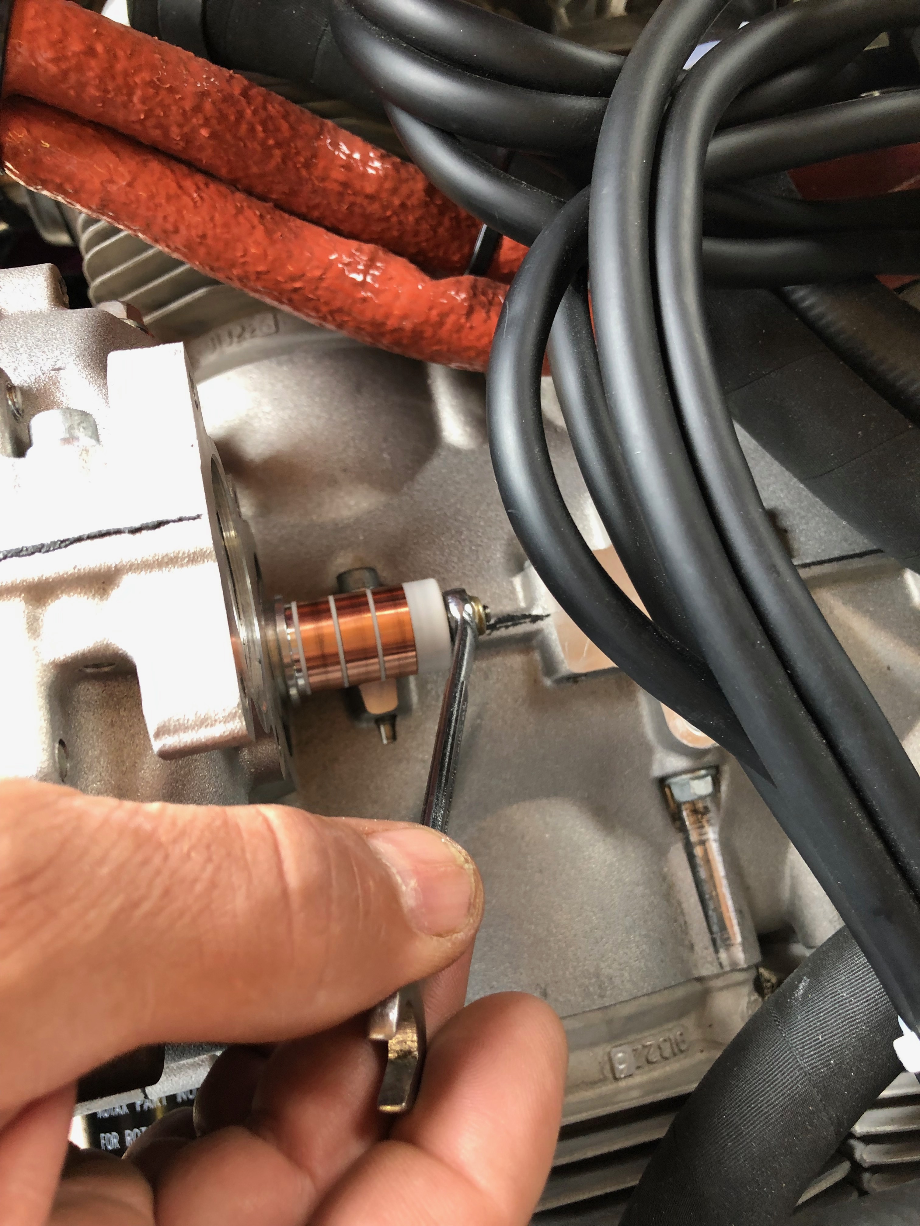
The fuel pipe from the selector to the tanks and engine need to be routed so they don’t kink and cut the supply whilst also being kept away from anything that may chaff them.This shows the support bracket for the park brake cable. It works well.The outer cables are wire locked to the adjusters so they can’t move once fitted.The demist control with the connector we made up. It looks a very good solution.At last the centre console’s complete with all the controls fitted, cables run and fuel pipes fitted. Having received the prop on Monday I can start to install the various bits. This is the mini slip ring available for Rotax 912ULS type 2 engines. It’s fitted to the rear of the gearbox.and then secured in place with a rod hat runs through the hollow gearbox shaft. The control wires spiral round the rod… and exit the front of the engine ready for connection to the pitch motor wires in the spinner.Once the slip ring is fitted the pick up bushes are installed. The bushes need run centrally on the slip ring. That’s all for the prop today, more tomorrow.Moving on to the panel again. I will fit as much as possible before fitting to the aircraft as it’s a lot easier than fitting the components when the instrument panel has been fitted to the aircraft. I’m not sure what Tom is doing here? Perhaps he’s going to start to sing? Captions please! He’s going home today so I’m solo again tomorrow!
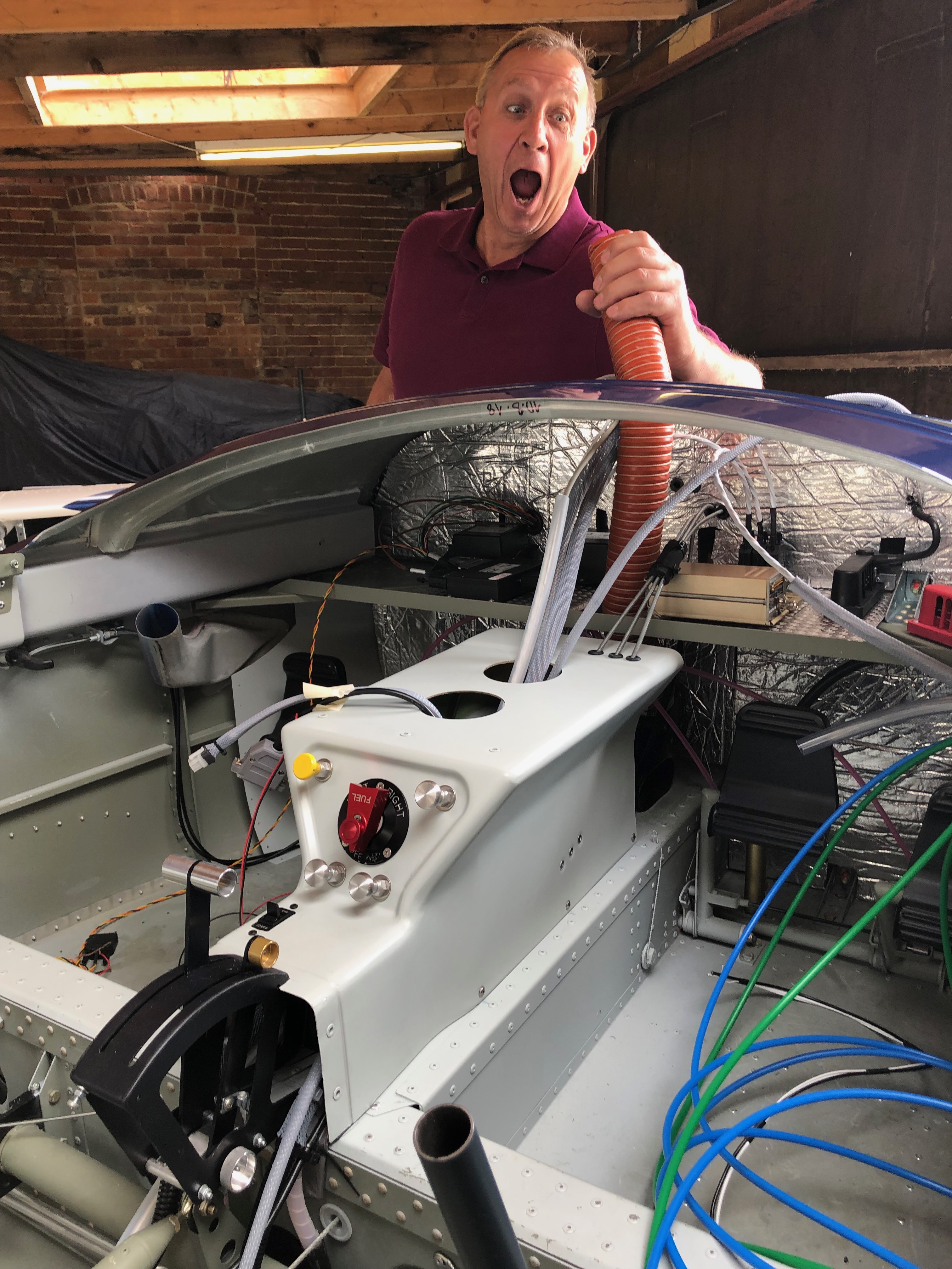
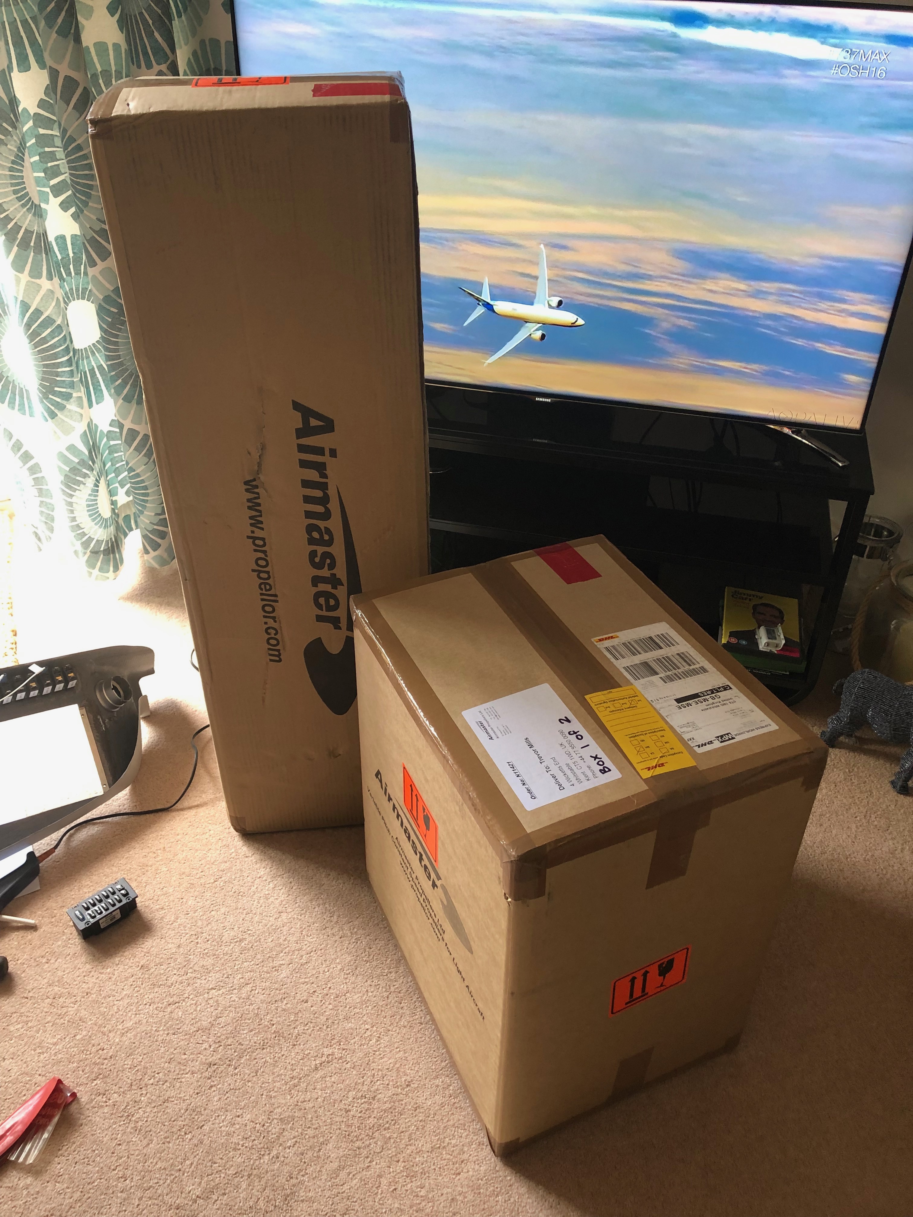
Good news – Today I’m expecting delivery of the Airmaster prop that was ordered in February. So I had brought back the switches and circuit breakers and thought that whilst waiting I would wire them up.
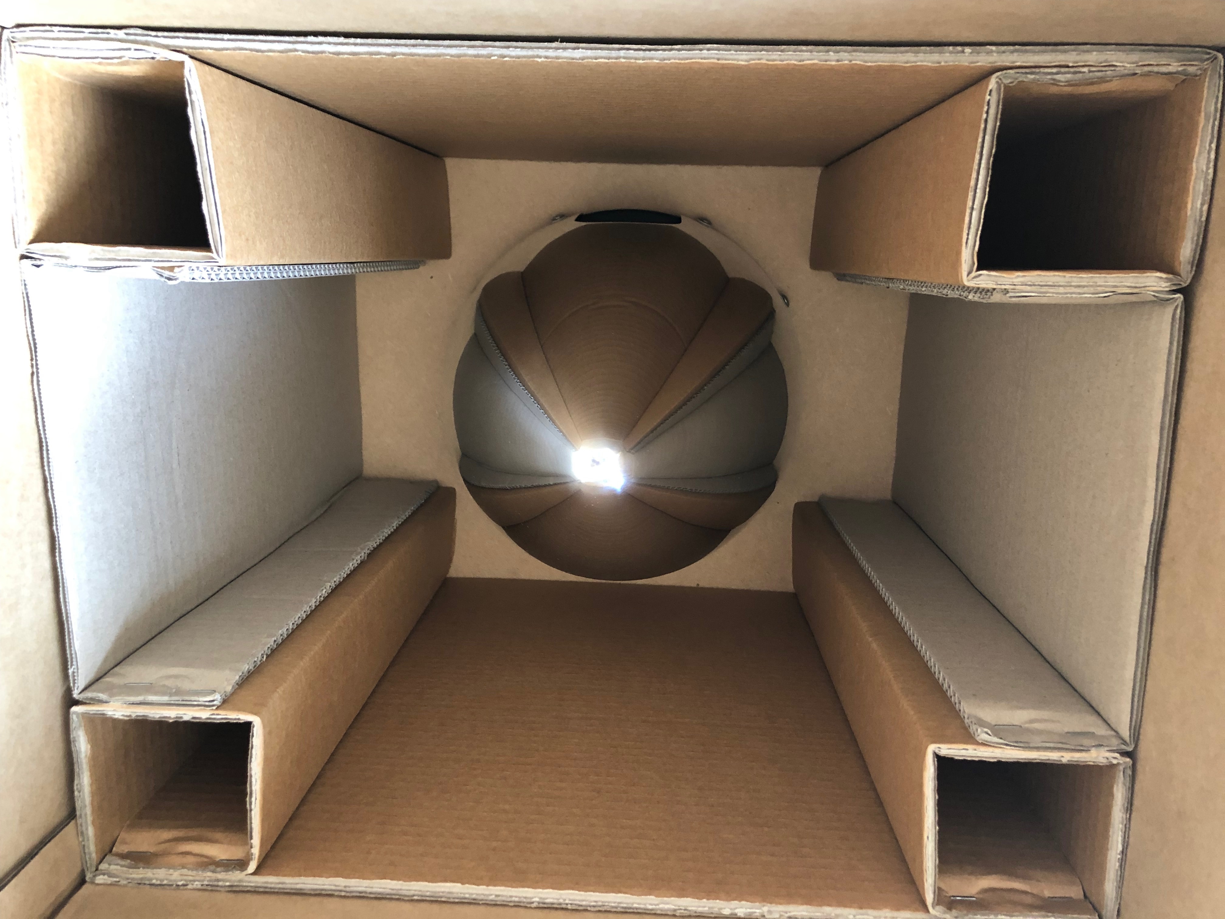
Each circuit breaker is linked to one or more switches depending on the circuit design by making a connecting wire with 22 or 18 AWG wire with a couple of crimped female spade connectors.The Aveo air vents were next and are secured by screwing the front and back components together.At last! I have finally received the Airmaster prop. On first inspection the hub and spinner box looked fine and undamaged and the inside…looks good too…However the box with the blades in had quite a substantial gash in the front. Luckily, although the cut went through both the outer and inner boxes, whatever caused it never hit the blades – Phew!One of the carbon fibre blades, looks very swish.
Finished the ADAHRS and GMU 11 mounts then primed and installed them. Spent some of the day investigating switches, circuit breakers and wiring.
Andy is coming over on Monday so we can look at getting some build stages signed off and possibly rig the aircraft to make sure every thing fits!
First thing was to drill the holes for the rivets….
and the holes for the devices that will be attached to the mounts.
The mount is sprayed with chromate primer and jointing compound is applied between the fuselage floor and the mounts to prevent corrosion.
The mounts are riveted from underneath the fuselage.
The GMU 11 mount installed and ready for the GMU unit to be added.
When I got home I got an early surprise of Airmaster. The controller and wiring loom had arrived from New Zealand. They were despatched on Tuesday so pretty quick to get here. I can install the wiring and controller in readiness for the delivery of the prop in late May.
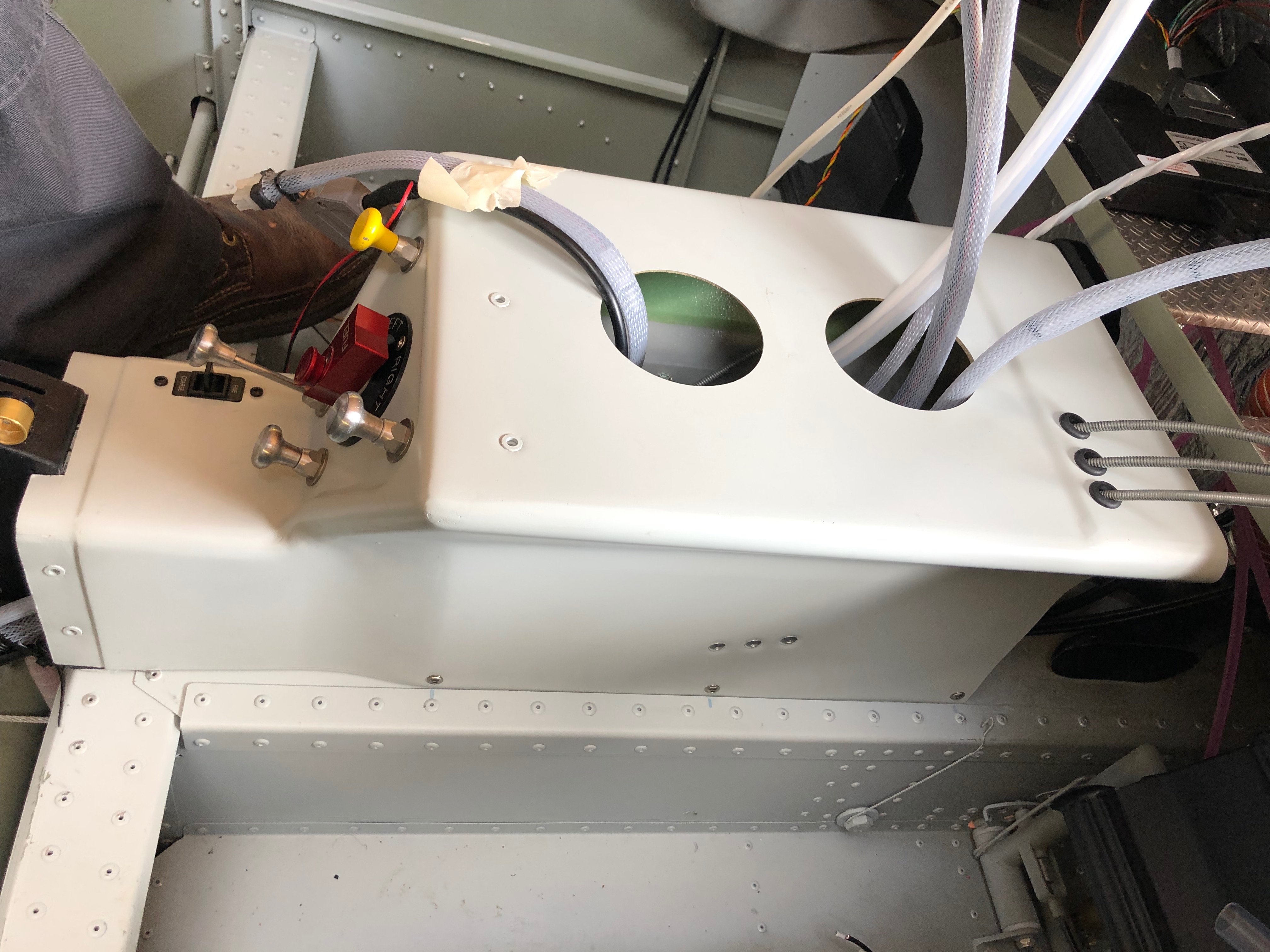
Some time ago I had assembled the Andair fuel selector but hadn’t installed it as it wasn’t needed at the time. Today was the day to mount the selector and various controls into the centre console.
On a lot of centre consoles I’ve seen, the fuel selector and the flap control are positioned side by side in this recess. Personally I thought it would be better to keep the fuel away from any electrics, so have decided to mount the flap selector on the instrument panel.
The centre console which is made from glass fibre and re-enforced with carbon fibre panels. I marked the centres and positioned the selector where I thought it would look good.
After measuring and remeasuring the position to drill the mounting hole I used a step drill to cut a 26mm hole. It was only after doing this I found that Andair actually provide a template to help do this. Note to self: RTFM!
No problem with my measurements though and the selector cover goes on ok. I can now mark up where the Carb heat, Park Brake, Heater, and Screen De-mist controls go.
Although there are strengthening panels build in to the console I thought it would be good to further strengthen where the push/pull controls are mounted so made a couple of brackets…
and use a piece of glass fibre to secure them in place. This further supports fuel selector and controls.
This is what it looks like after the glass fibre has set.
Re-drill the holes
and the finished console ready for the the selector and controls to be mounted.
The cables are secured in place with nuts and I’ve put another washer on the back to spread the load even more. Taking no chances!
The inners are inserted to finish off. I will be able to mount the console and work out the runs for all the cables and make sure they work in the correct sense i.e. Pull for on, push for off.
There are 2 brackets that secure the instrument panel and the centre of the panel is supported by the console.
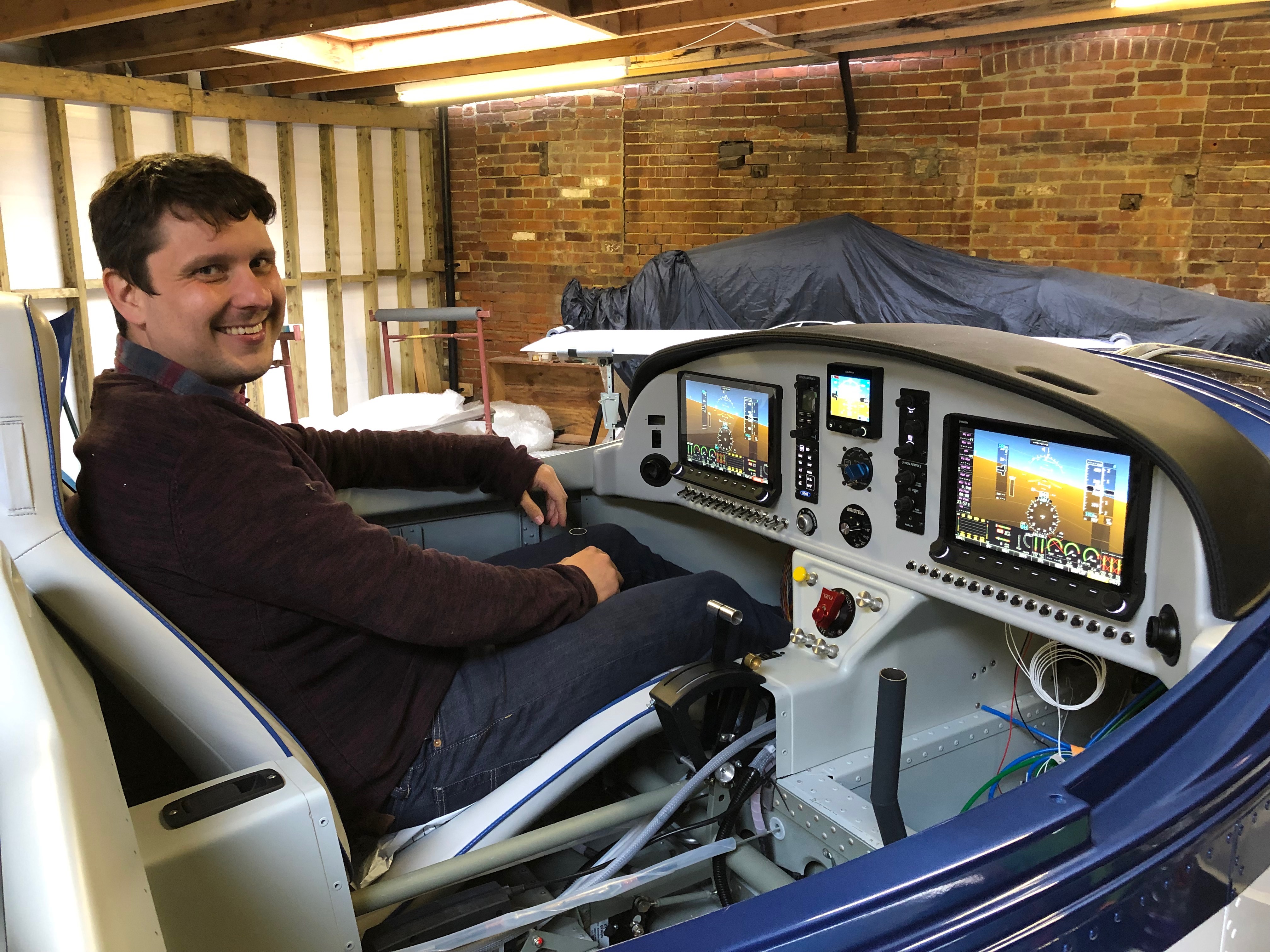
The console and instrument panel temporarily installed to see how it looks/works. I can now prep for the install of the screens and various switches, circuit breakers and warning lights once I’ve completed my electrical design.
Music: The Greatest Showman reimagined and Snow Patrol.
Finishing off the insulation installation, first fit of centre console, autopilot servo install and filling brake system with Aero Shell 41.
One quick job this morning now all the other pipes have been fitted is to run a piece of piping from the water expansion chamber to the water bottle.
I have been given templates for the insulation so I can cut them to size without too much effort.
Some notches, cuts and holes need to be made to make sure it sits properly on the firewall.
It’s a tight fit behind the rudder pedals which makes it difficult to handle once the backing paper has been removed.
The final pieces are fitted around the heated inlet.
The finished insulation, hopefully this should reduce noise from vibration of the firewall and the engine.
Now the servos brackets are in position the servos can be fitted. First the roll servo.
It’s very fiddly and would have been much easier to fit the servo to the bracket whilst it was out of the aircraft.
The pitch servo with the movement limiting bracket fitted which stops the motor running over centre. I still can’t finish the installation as there were items missing from the kit supplied to me – very frustrating as I can’t refit the controls until I fit the roll servo arm.
A first fit of the centre console in readiness for the fuel selector. Need to check with the instrument panel in place to check that the flap control cable is long enough to fit on the panel otherwise is will need to be mounted here instead which I would like to avoid.
After fitting the insulation need to reconnect and tighten the brake hoses before filling.
The brake fluid is filled from the bottom so some plastic pipe is wire locked onto the brake calliper nipple so stop it slipping off. The nipple is unscrewed to allow the fluid to flow into the calliper.
An oil can that has been thoroughly cleaned is filled with Aero Shell 41 and the plastic pipe is fitted to the nozzle.
The filling commences after releasing the park brake valve.
When the fluid reaches the brake oil bottle the brake calliper nipple is tightened and the process is repeated for the lefthand side brakes.
Filling complete but some air bubbles are present. They will need to be purged before use otherwise the brakes may not operate properly.
Due to limited space I couldn’t drill the second set of holes for the retention system. Luckily Ian had a 90 degree attachment the allowed me to drill the holes.
The holes for the rivets that will secure the bracket.
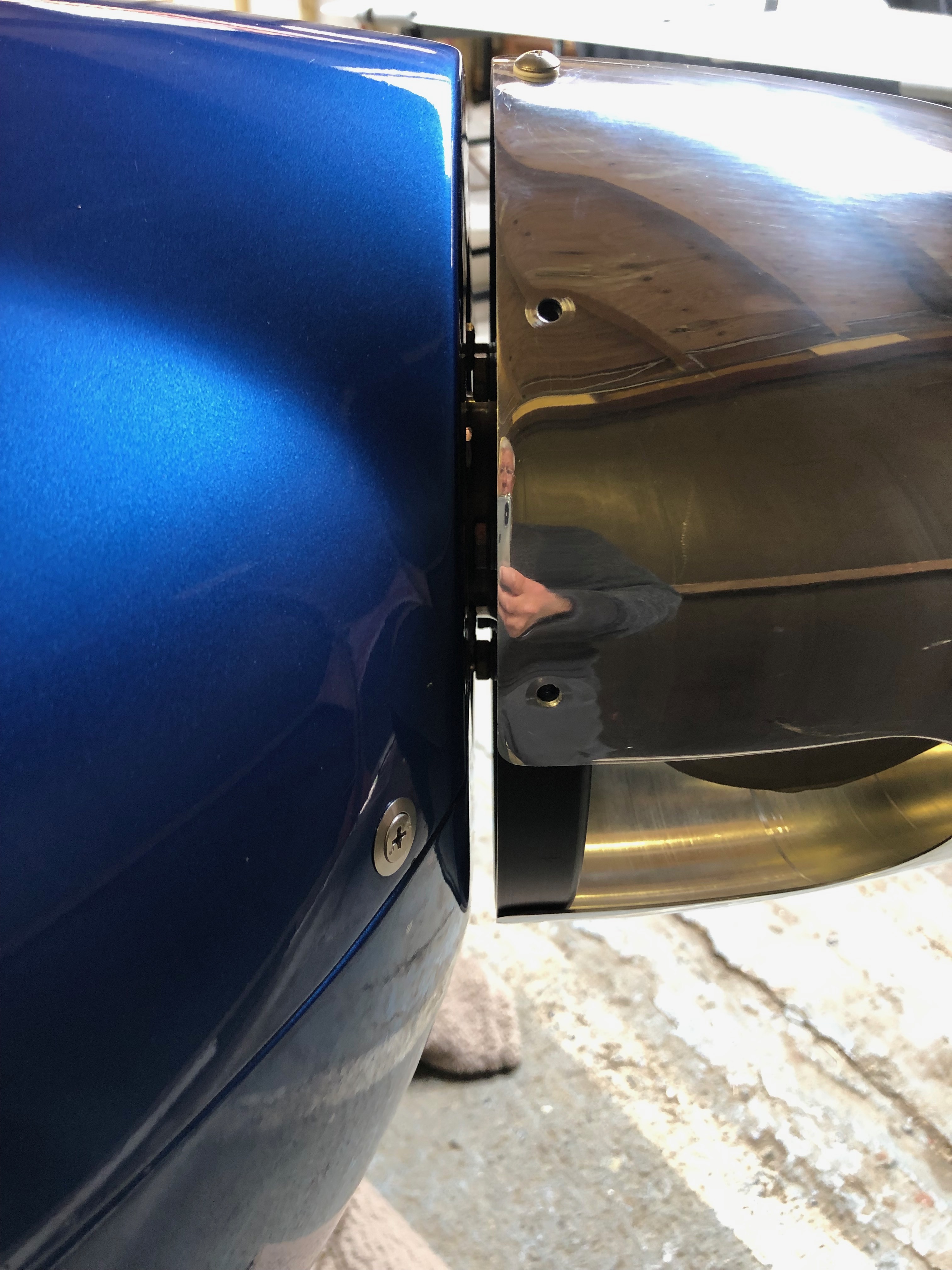
Sometimes you have to leave certain jobs because an immediate opportunity comes up for someone to help you swap wings. This is what happened when I had starboard wing up on the stand so I didn’t get chance to fit the strobe light. So today’s the day to do it.
Once the holes are drilled they need to be countersunk otherwise the strobes won’t fit flush.
Some Loctite 243 on the screws and then they are pinched up, not too tightly, otherwise they will disfigure the rubber mount.
The finished job, let’s hope it matches the other wing!
A job I kept forgetting to do is to add a breather pipe to the oil tank.
Now they can be secured with the drip tray and air intake breather tubes that Andy fitted yesterday.
I wanted to try to reduce the amount of vibration and droning from the firewall and noise from the engine. I purchased some sound & vibration deadening heat resistant foil back foam that will do the job.
After cutting to size, I’ve made the service holes to match the firewall and added grommets to make it a neater job.
I used some thinners to remove the printing on the foil before fitting. Looks a good fit.
I now need to undo some of the work I’ve done on the brakes and fit the front lower panels so I can fit sound deadening on the firewall behind the rudder pedals but run out of time today so will finish this job Monday.
Following the build of my Bristell NG5 Kit No. 382 Registration G-MLSY