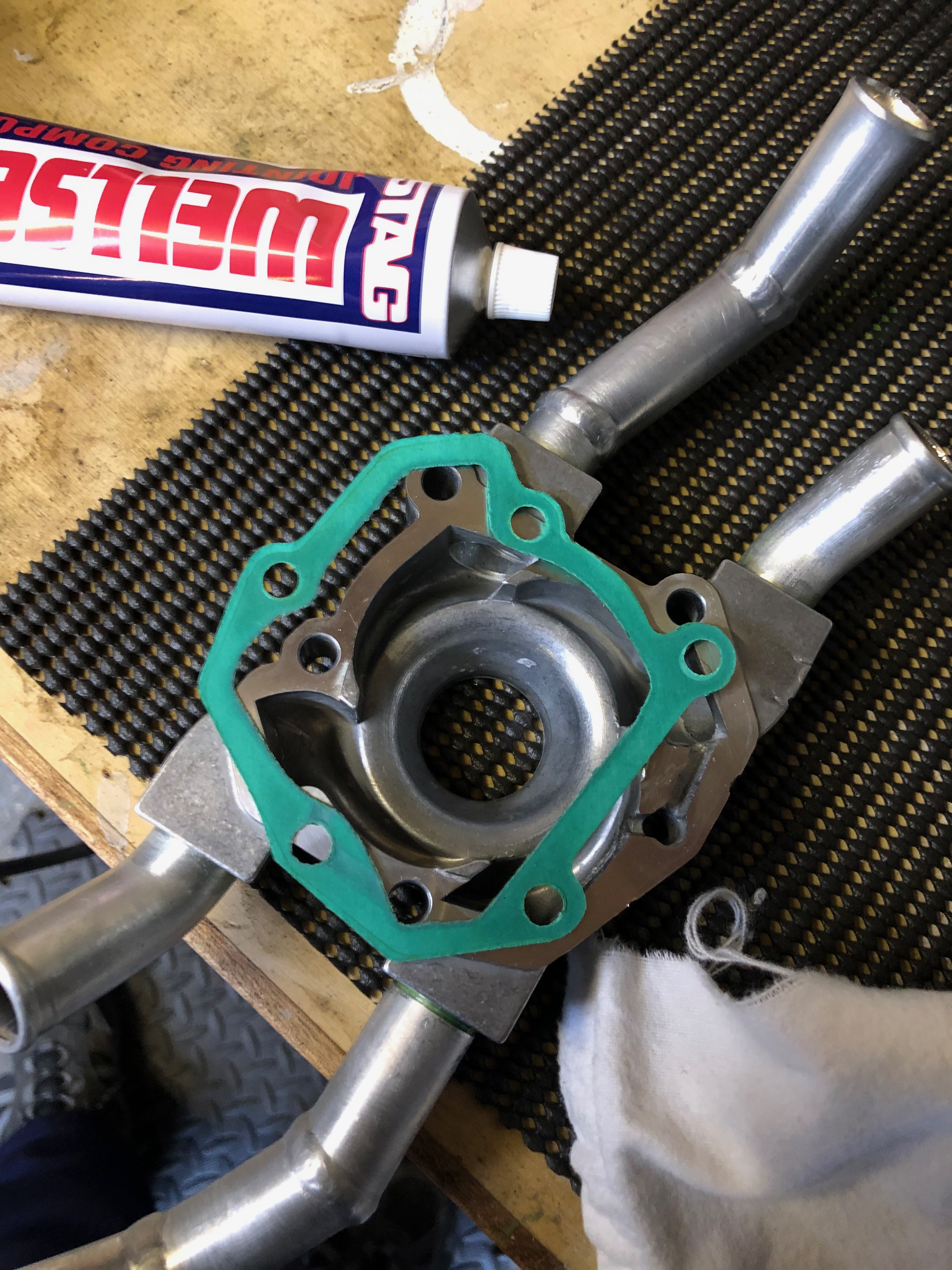
Now the Loctite has set the pump can be rebuilt, The mating faces and gasket were degreased and Wellseal applied, left to set before being reassembled.
The impeller cover seal is also refitted after a bead of Wellseal is applied. All bolts were then tightened to the correct torque.
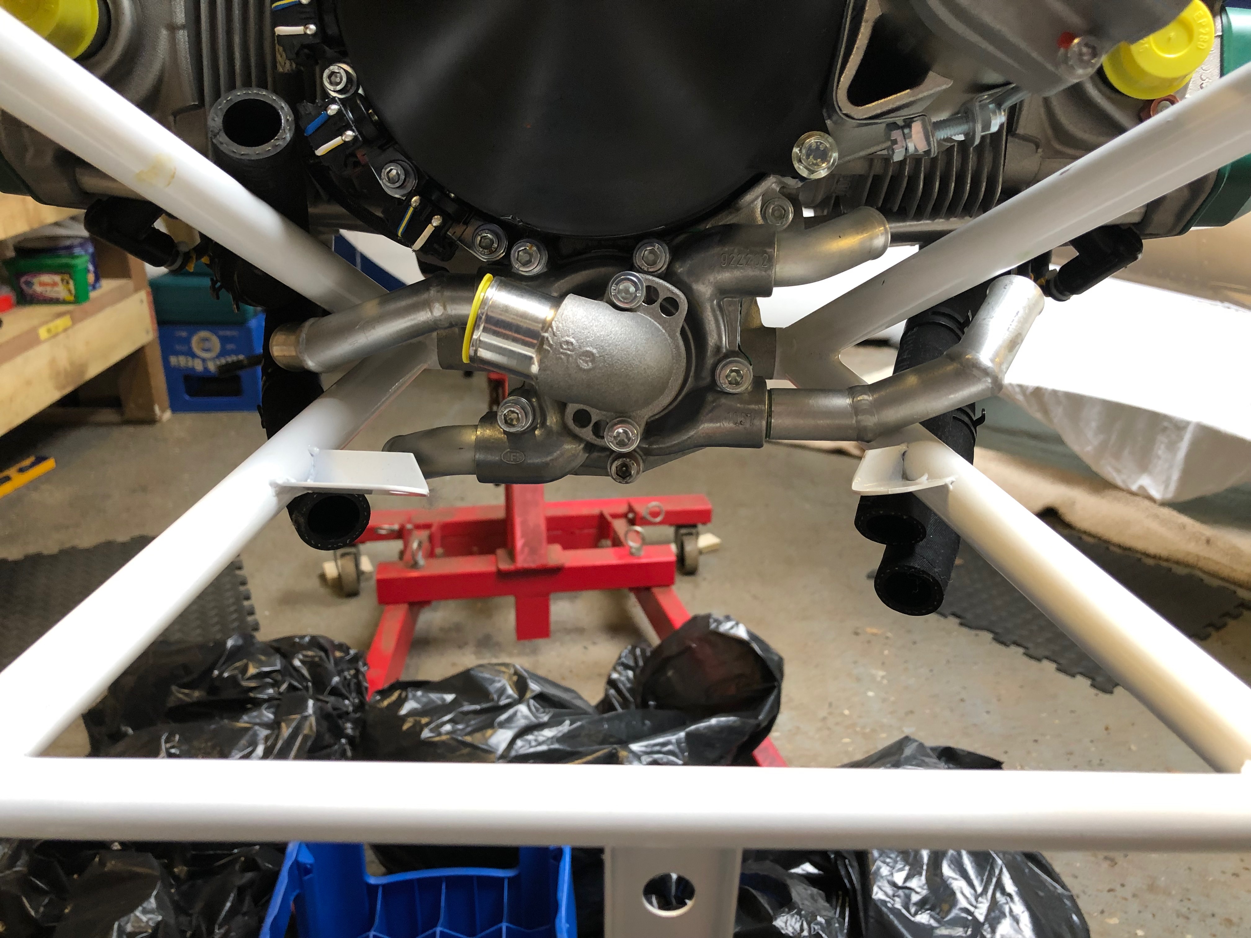
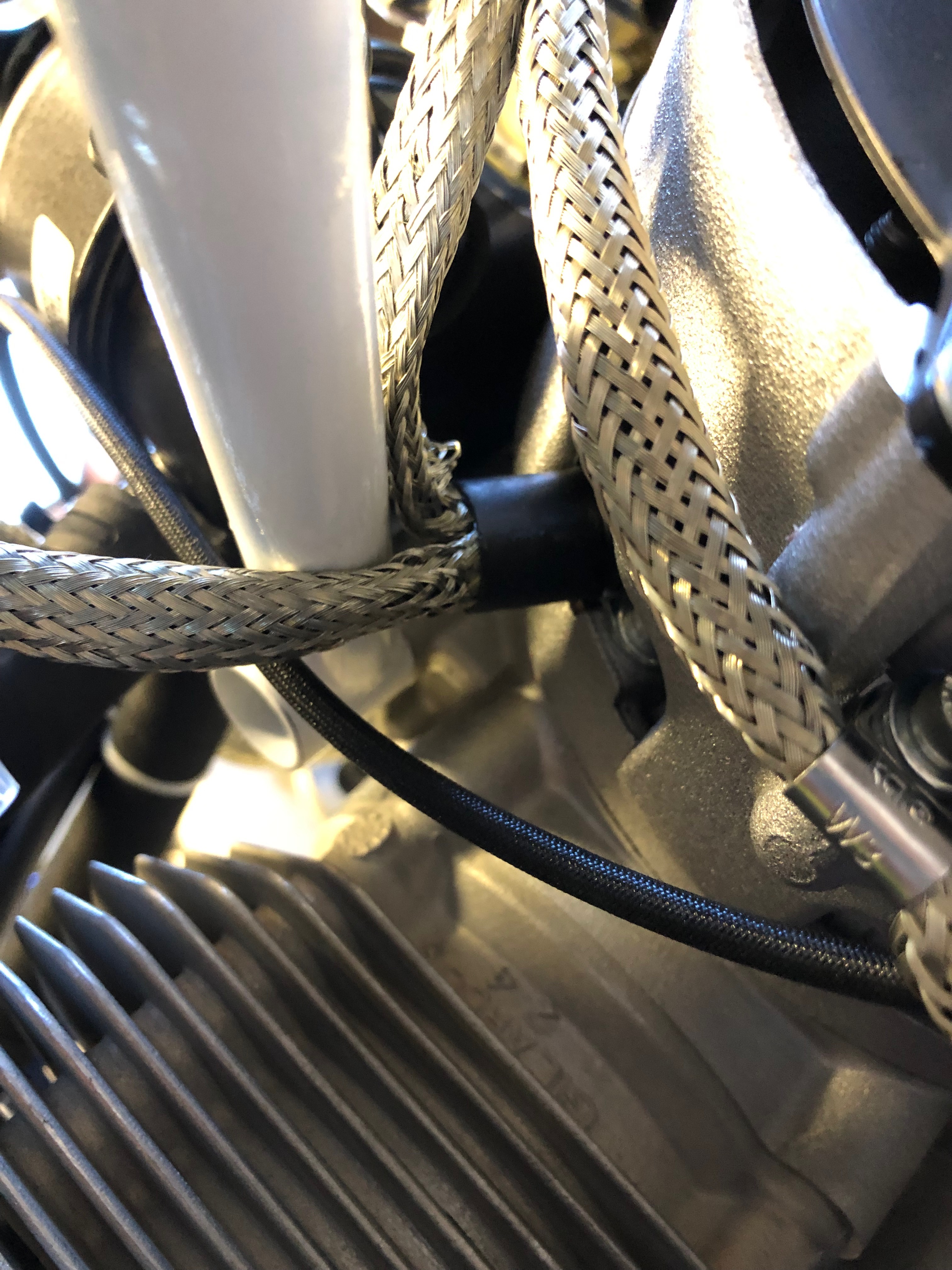
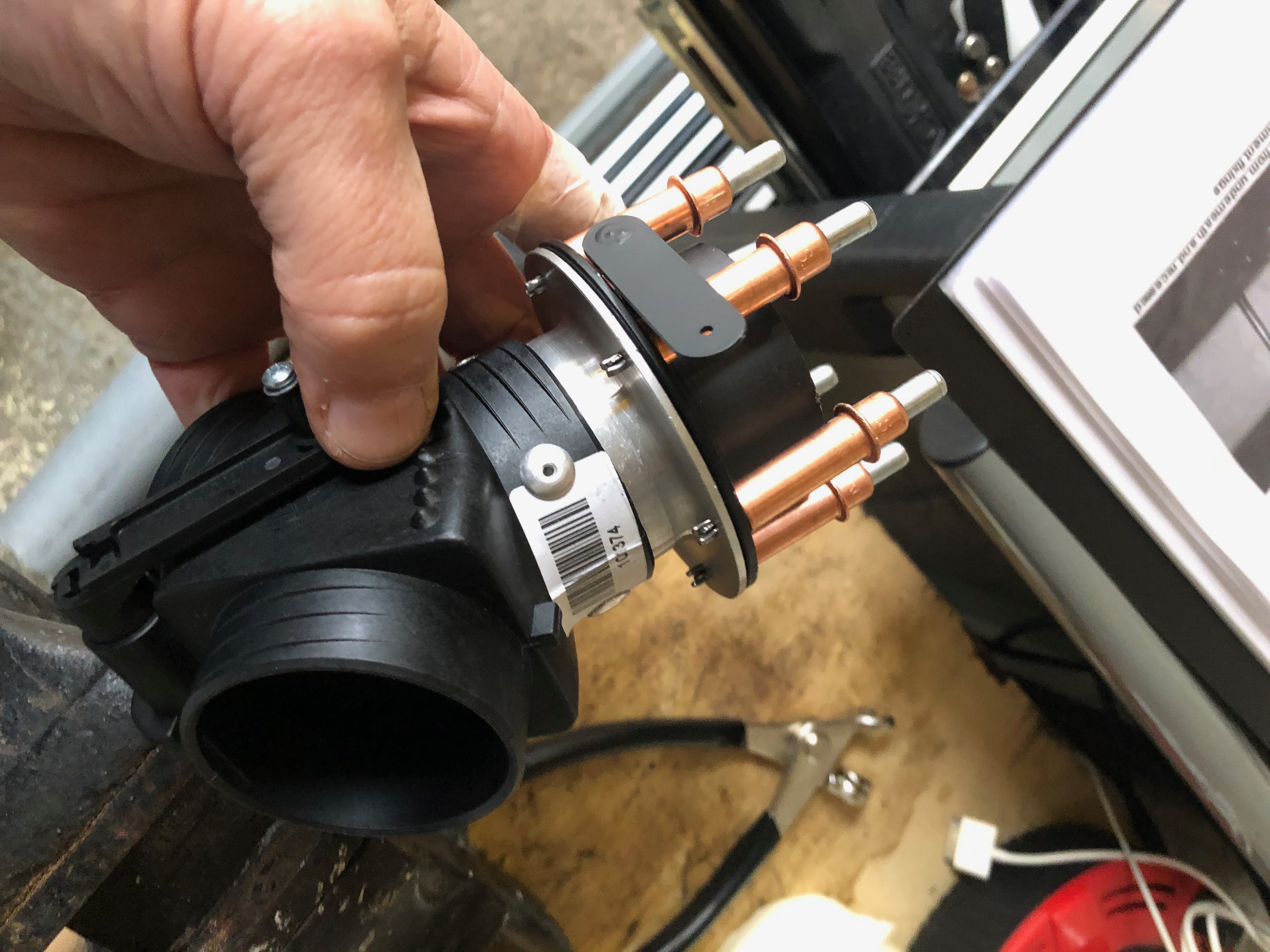
The water pump refitted clearly showing the new position of the modified pipes around the Bristell engine mount. The rubber pipes will be refitted tomorrow allowing the Loctite to further harden.
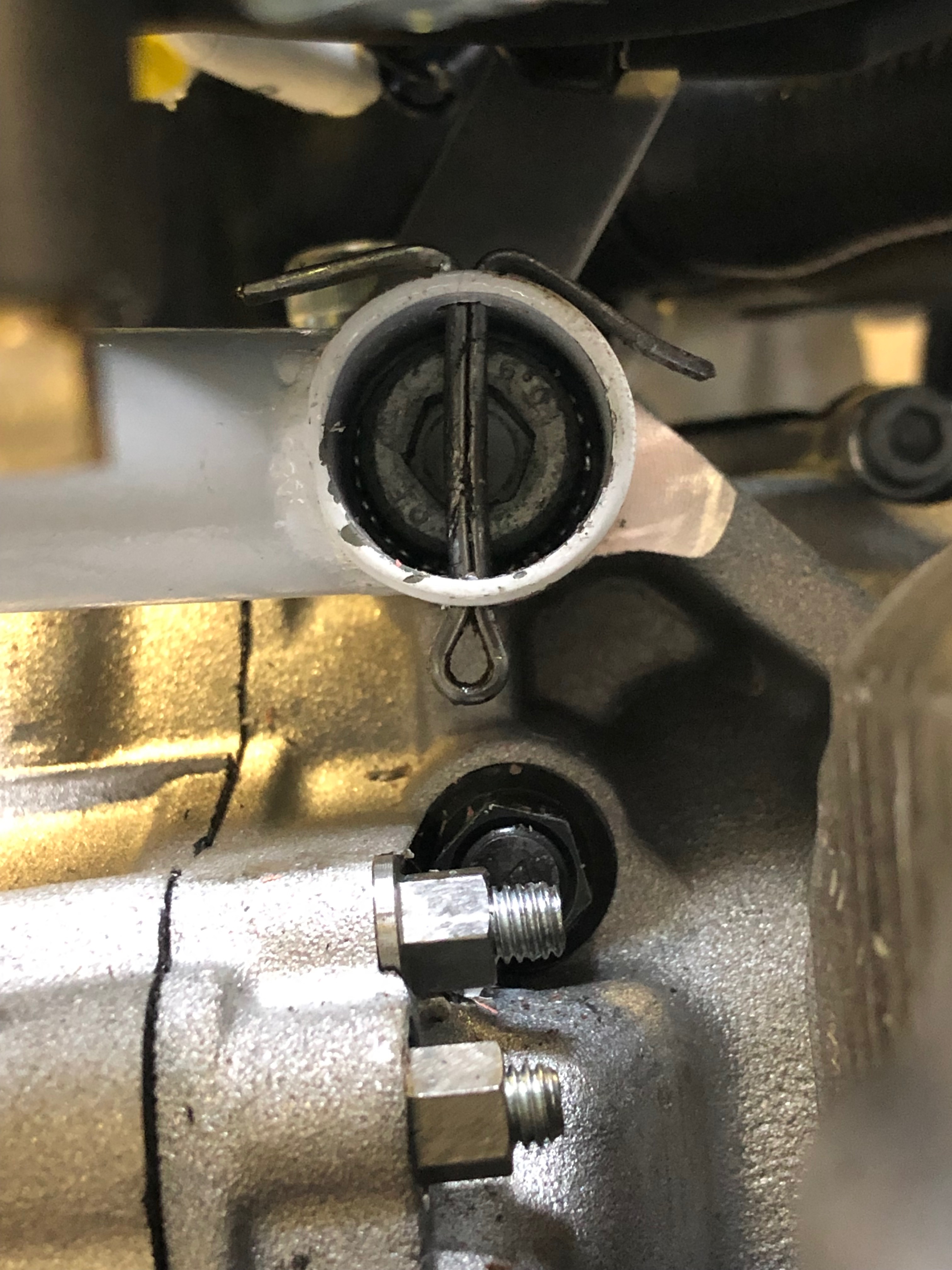
Split pins are inserted through the engine mount to retain the engine bolts should they loosen ensuring that they won’t fall out when in service.
Three of the split pins are easy to install but top right is impossible without taking the control unit off so this one was installed upside down but still does the job of retaining the bolt should it work loose.
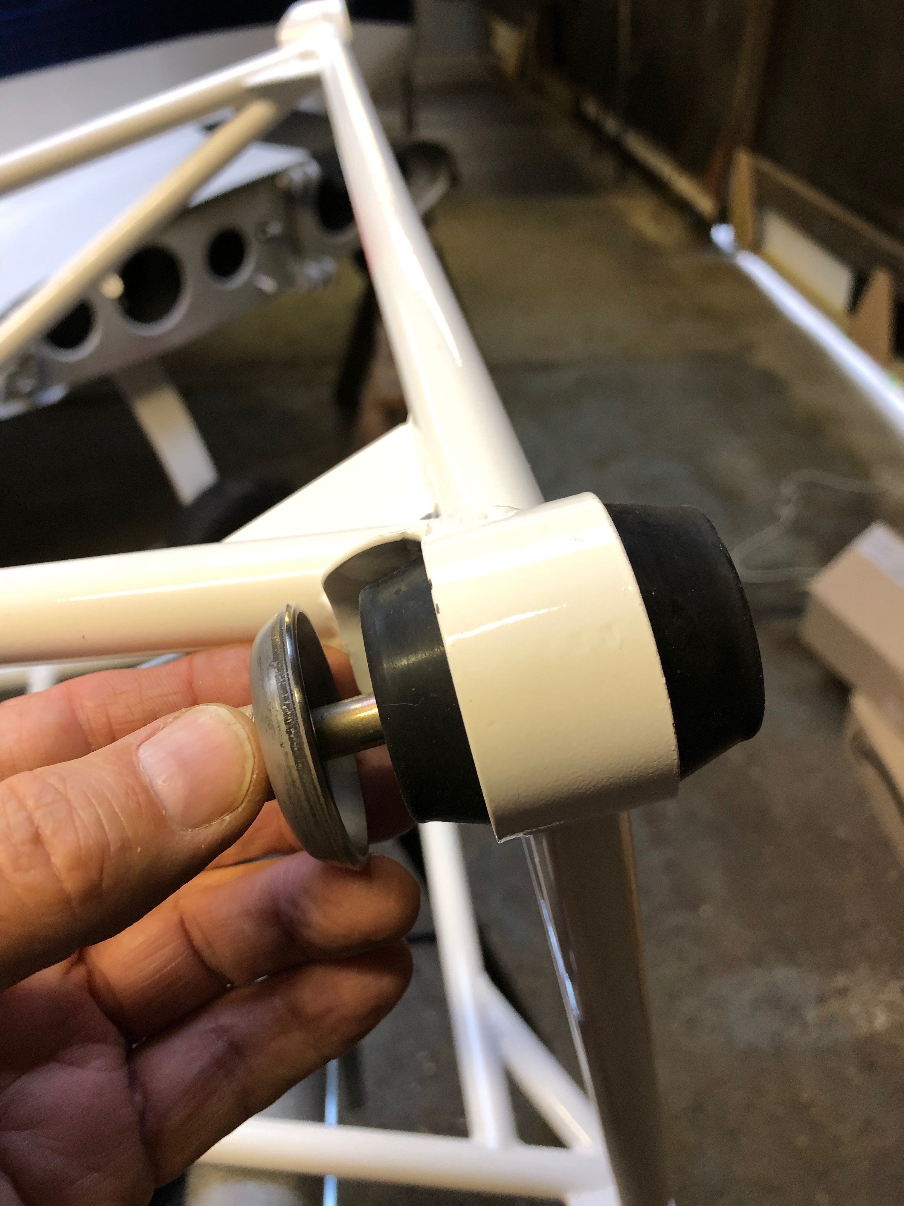
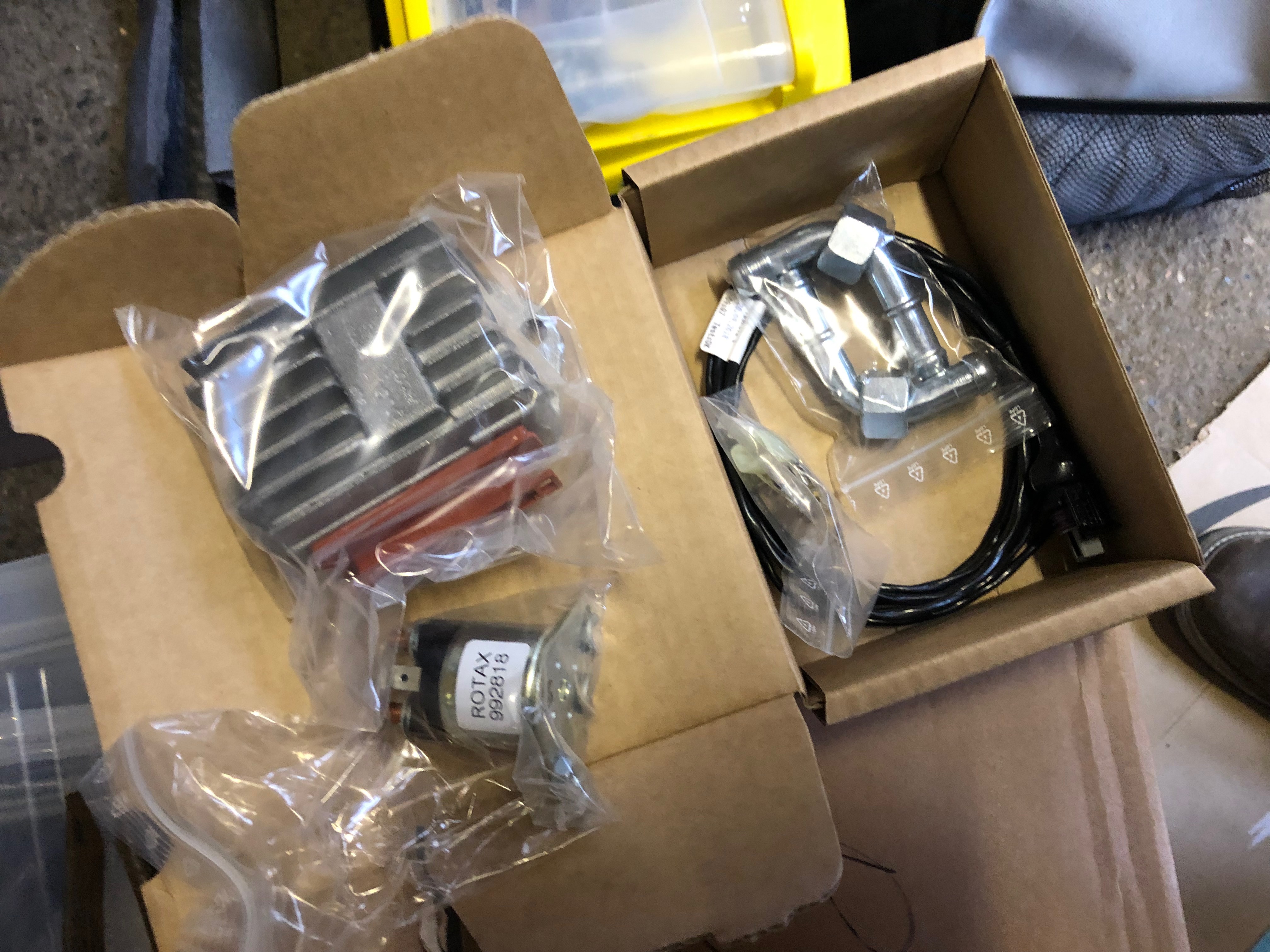
I test fitted the engine vibration bushes onto the engine mount in preparation for hanging the engine tomorrow.
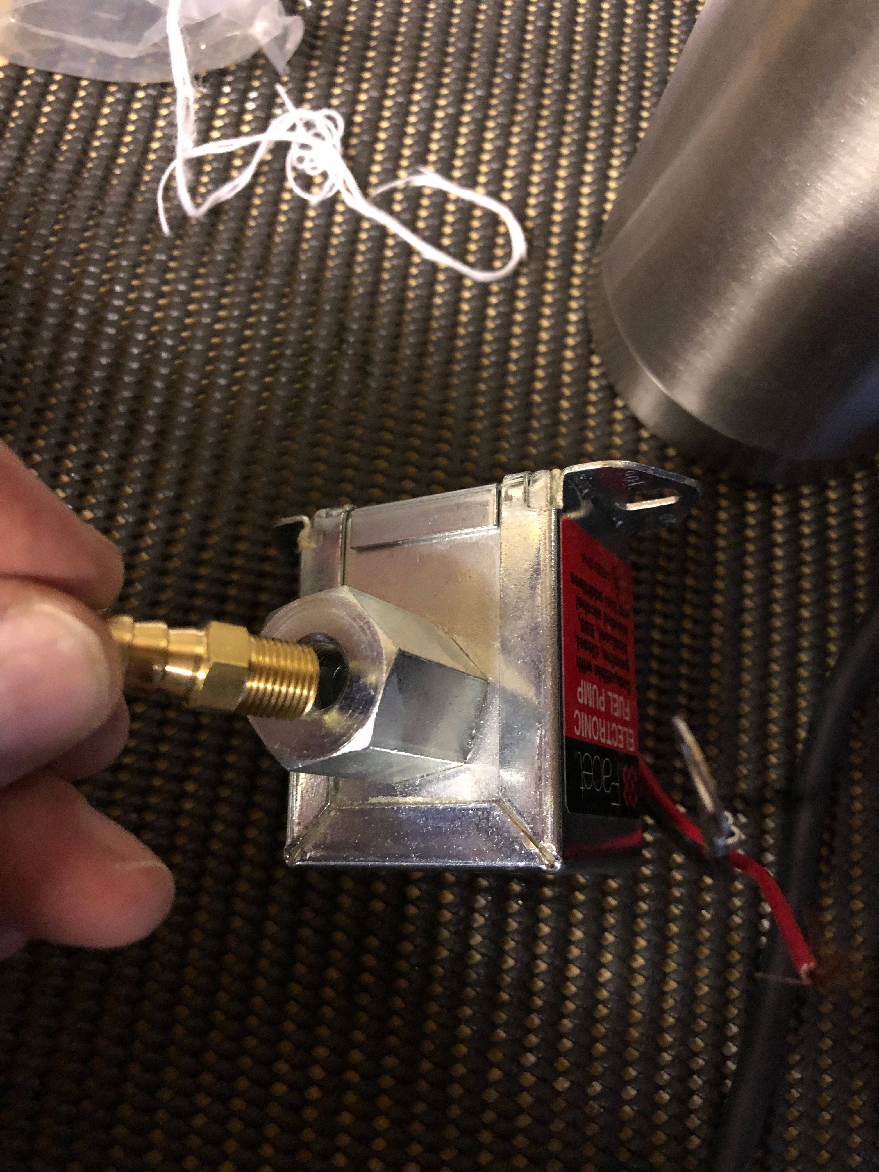
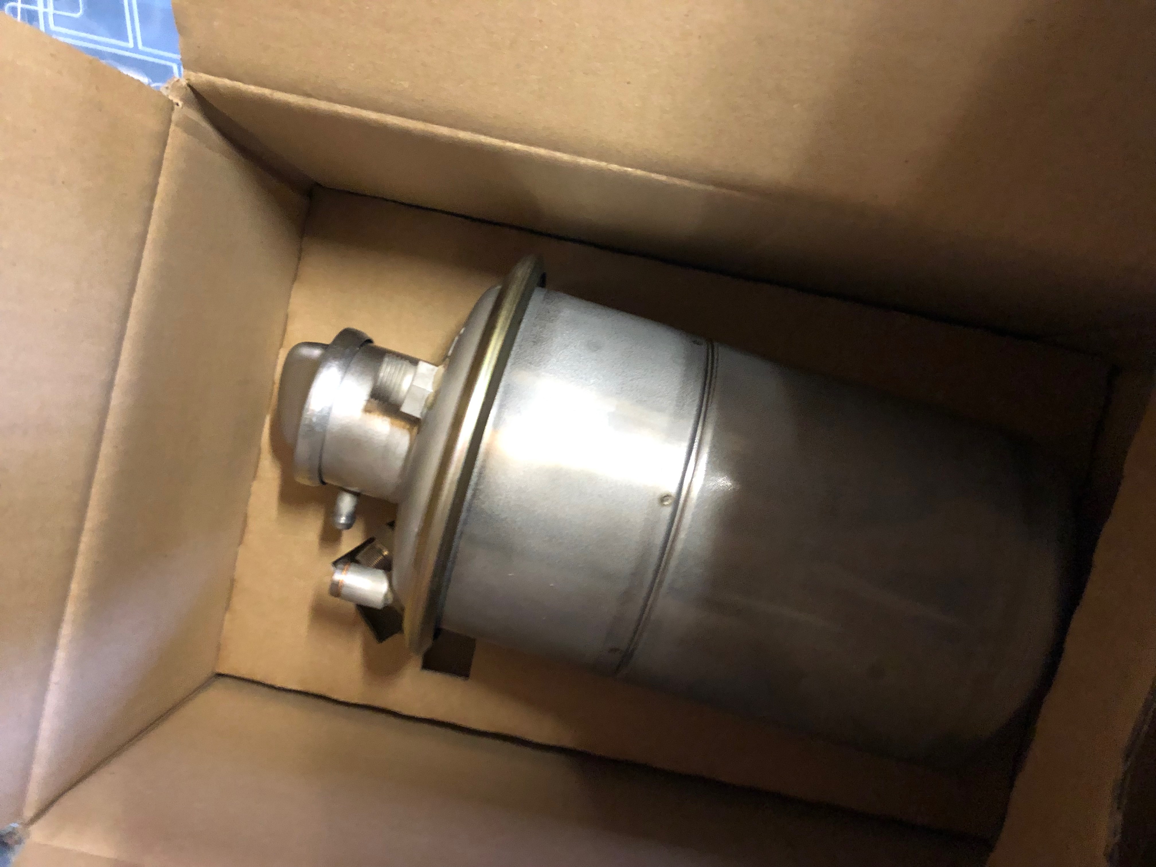
One of the miscellaneous tasks that needs to be done. The electric fuel pump fittings are screwed in after applying Wellseal around the thread ensuring the ‘water tight’ seal.
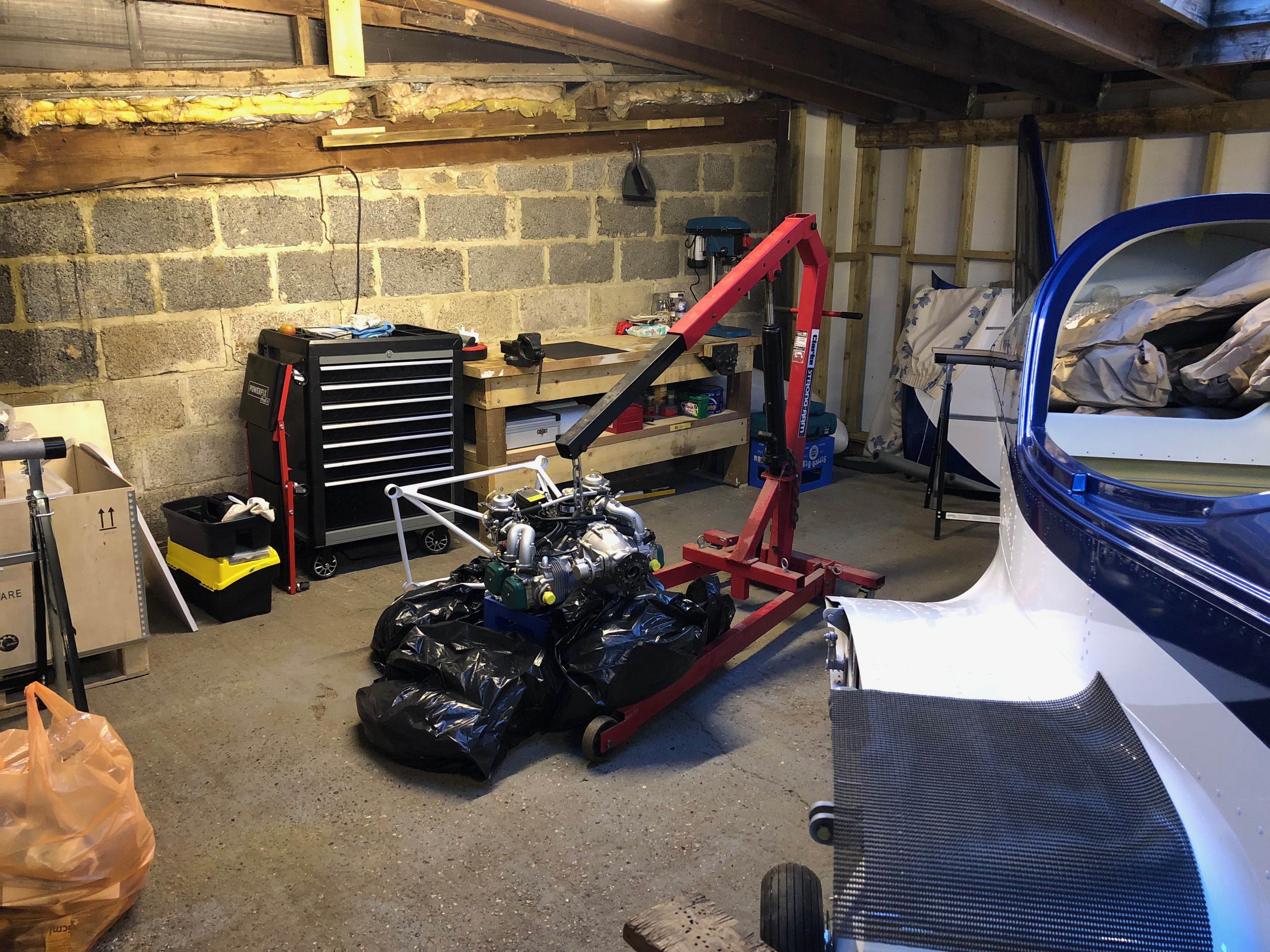
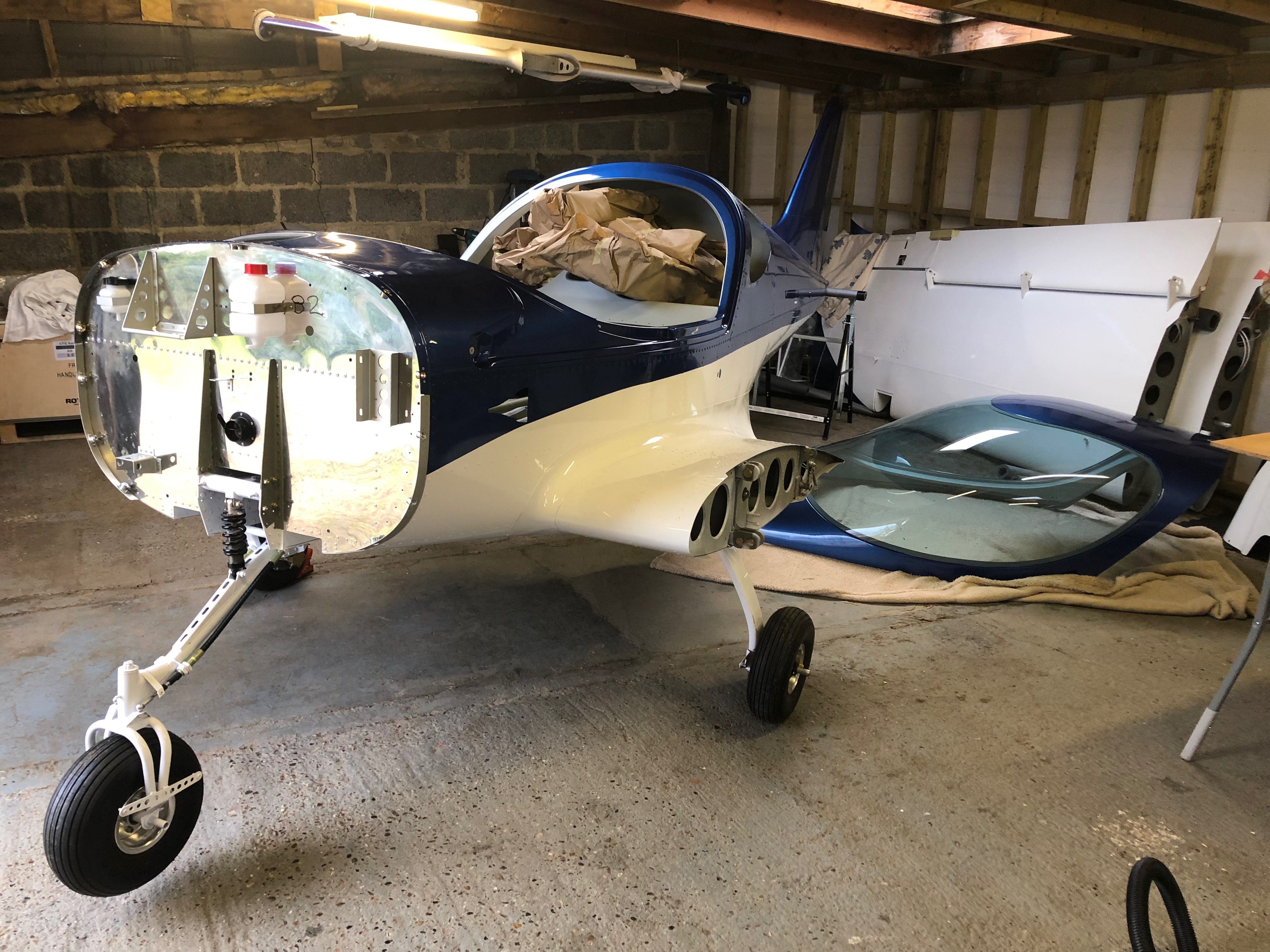
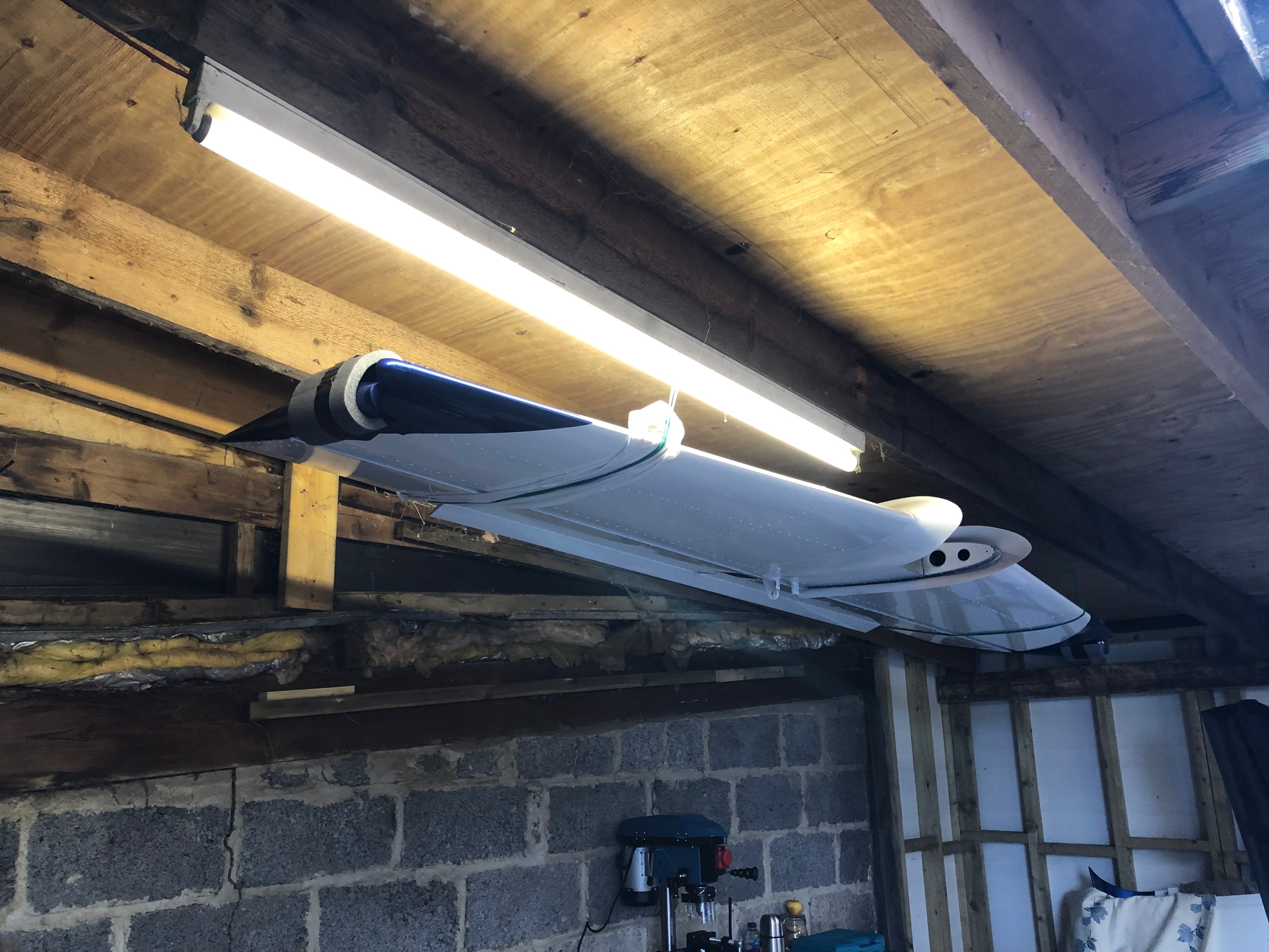
The usual resting place overnight. Hopefully the last time I’ll have to do this!
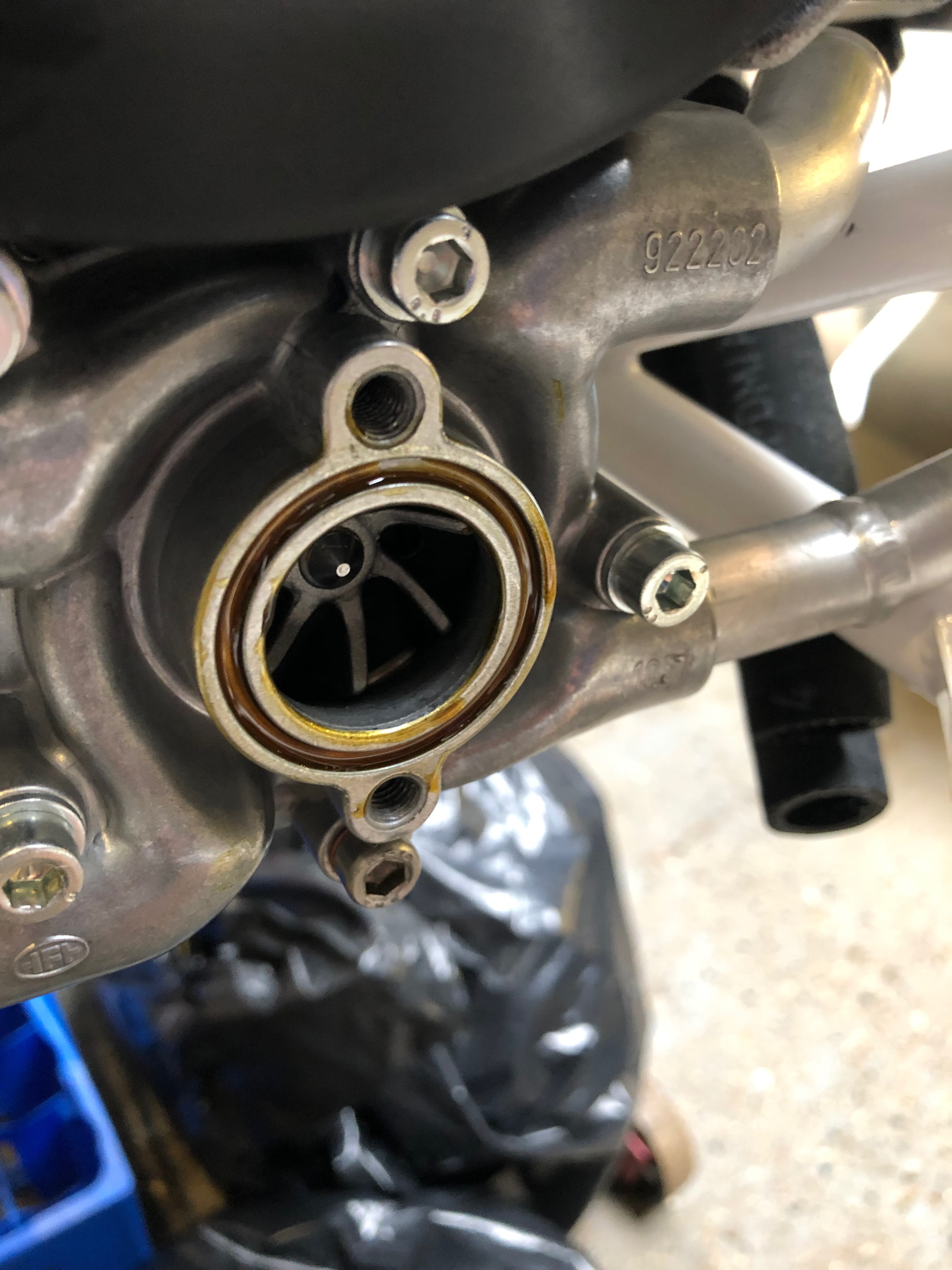
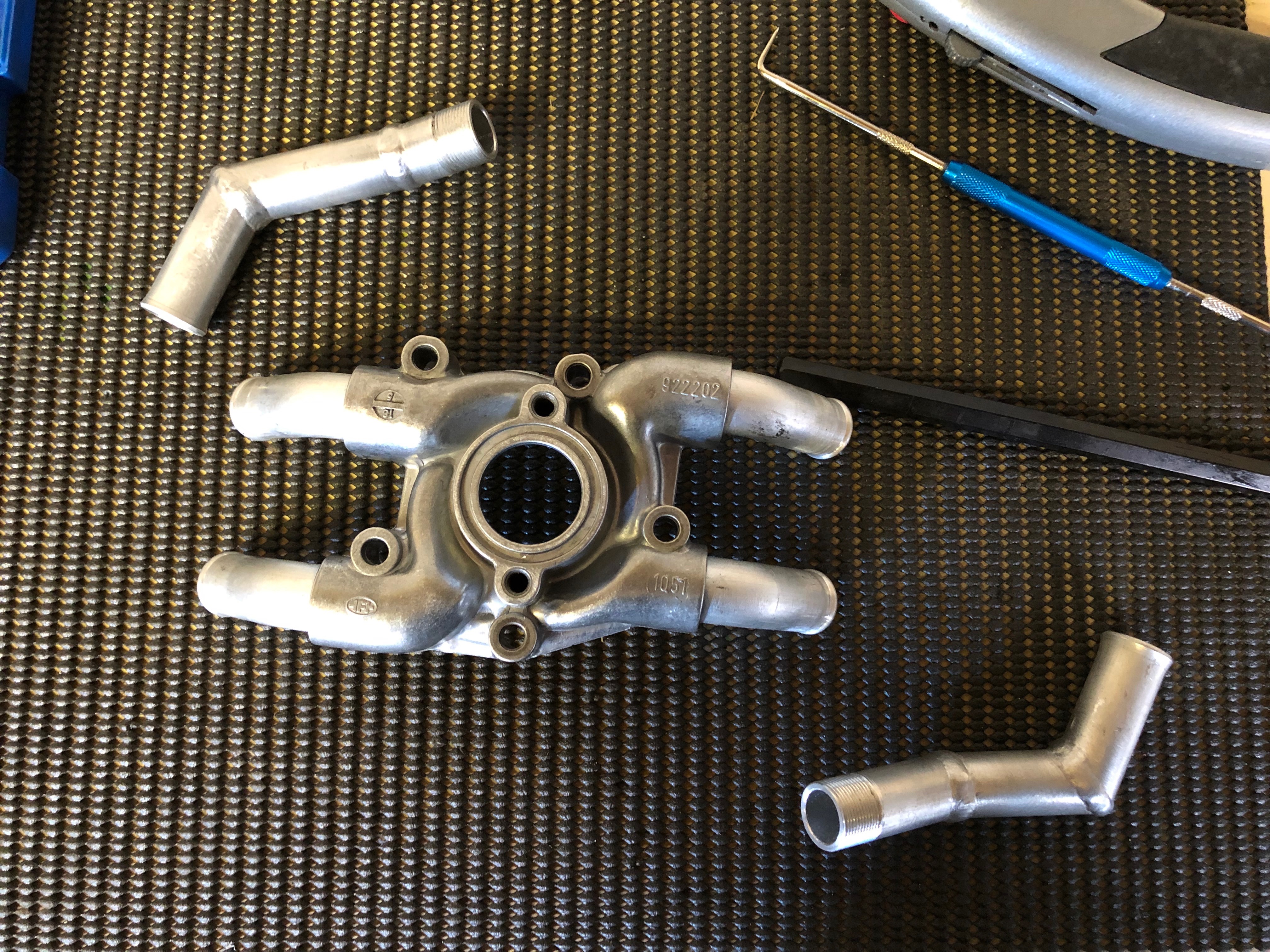
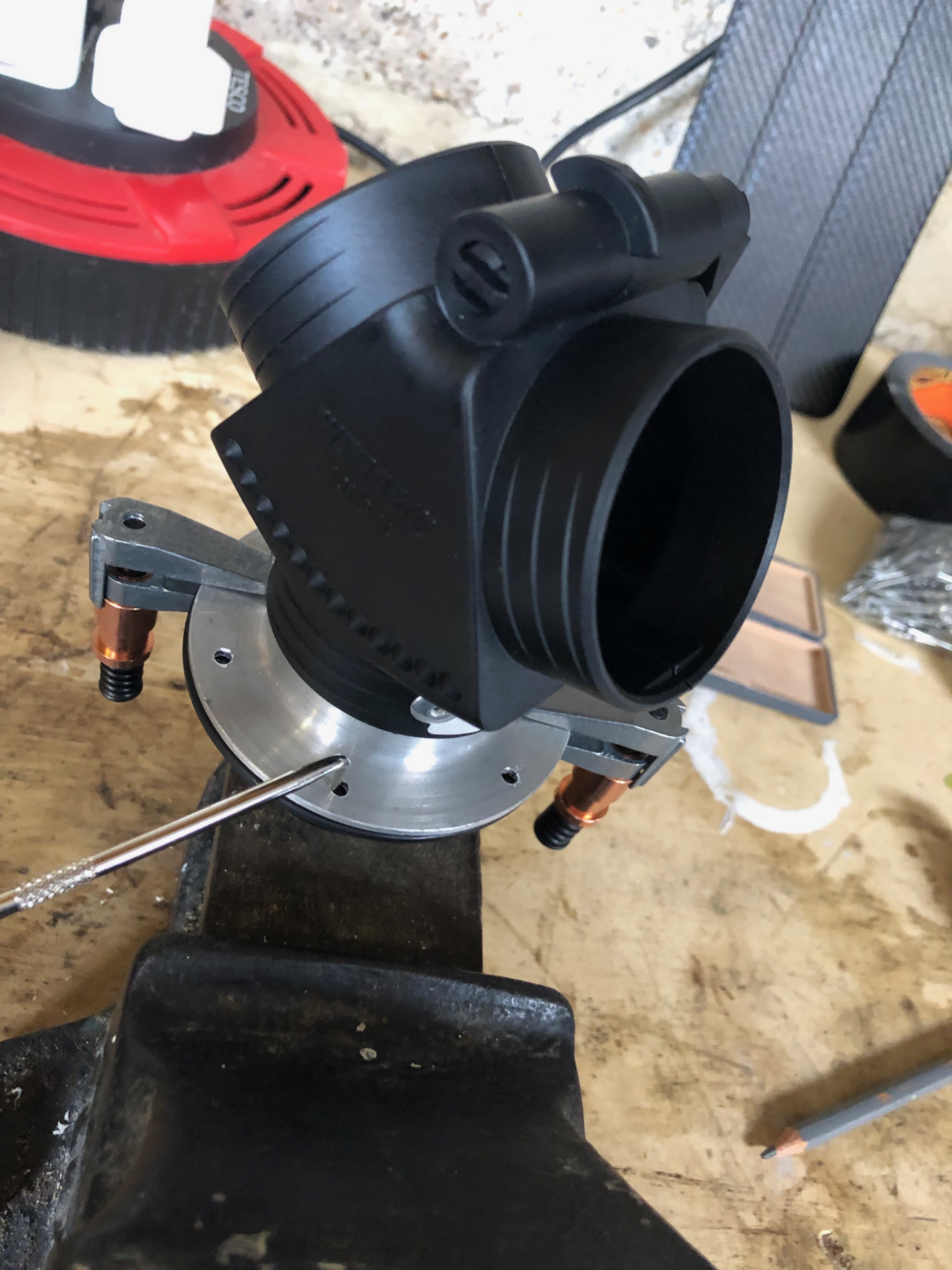
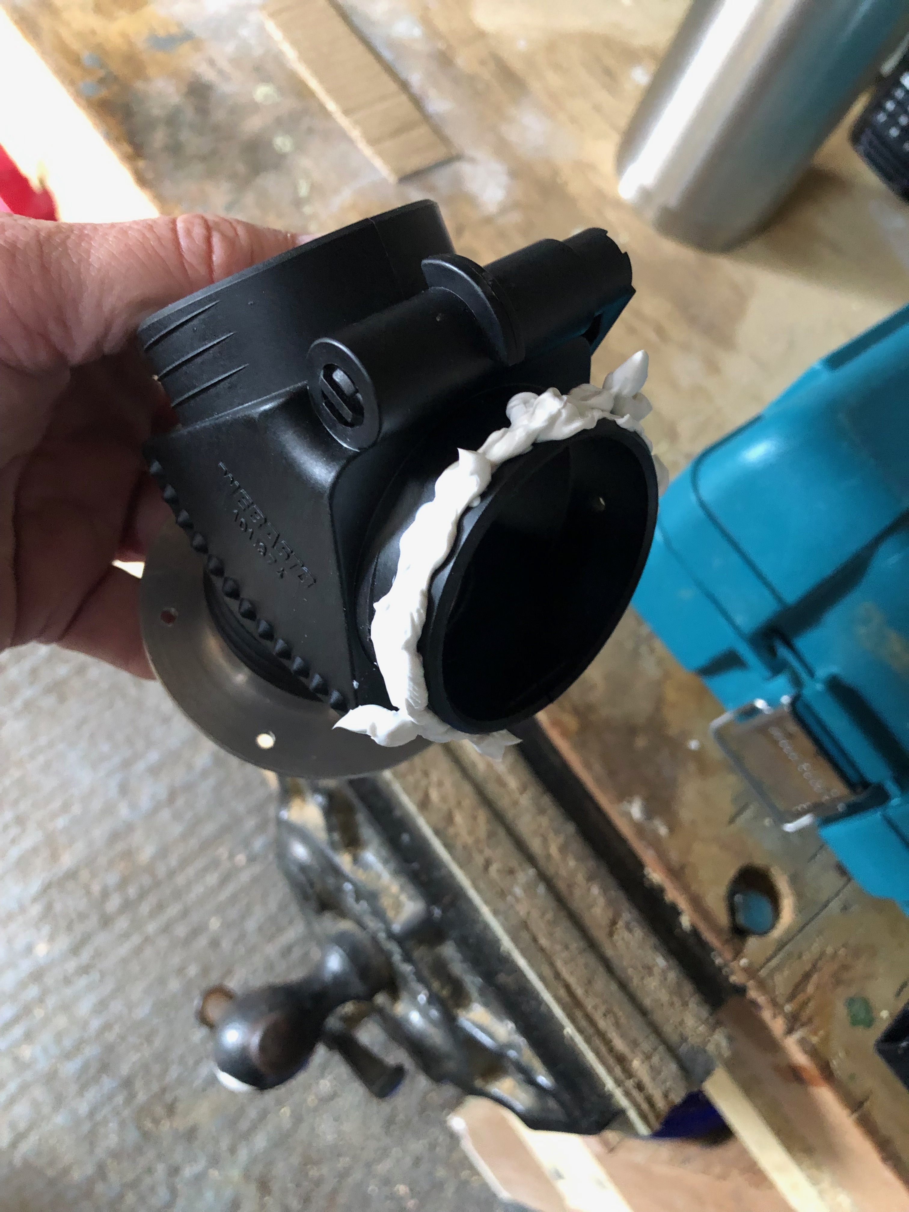
Time to modify the pump. The top left and bottom right pipes will be changed and the other two will be removed and refitted at a different angle to suit the Bristell engine mount.
The pump and pipes are heated until the existing Loctite bubbles and then a long bar is used to unscrew the pipe. This is repeated for all four pipes.
The old Loctite is removed by using a scribe and some thinners ready for reuse.
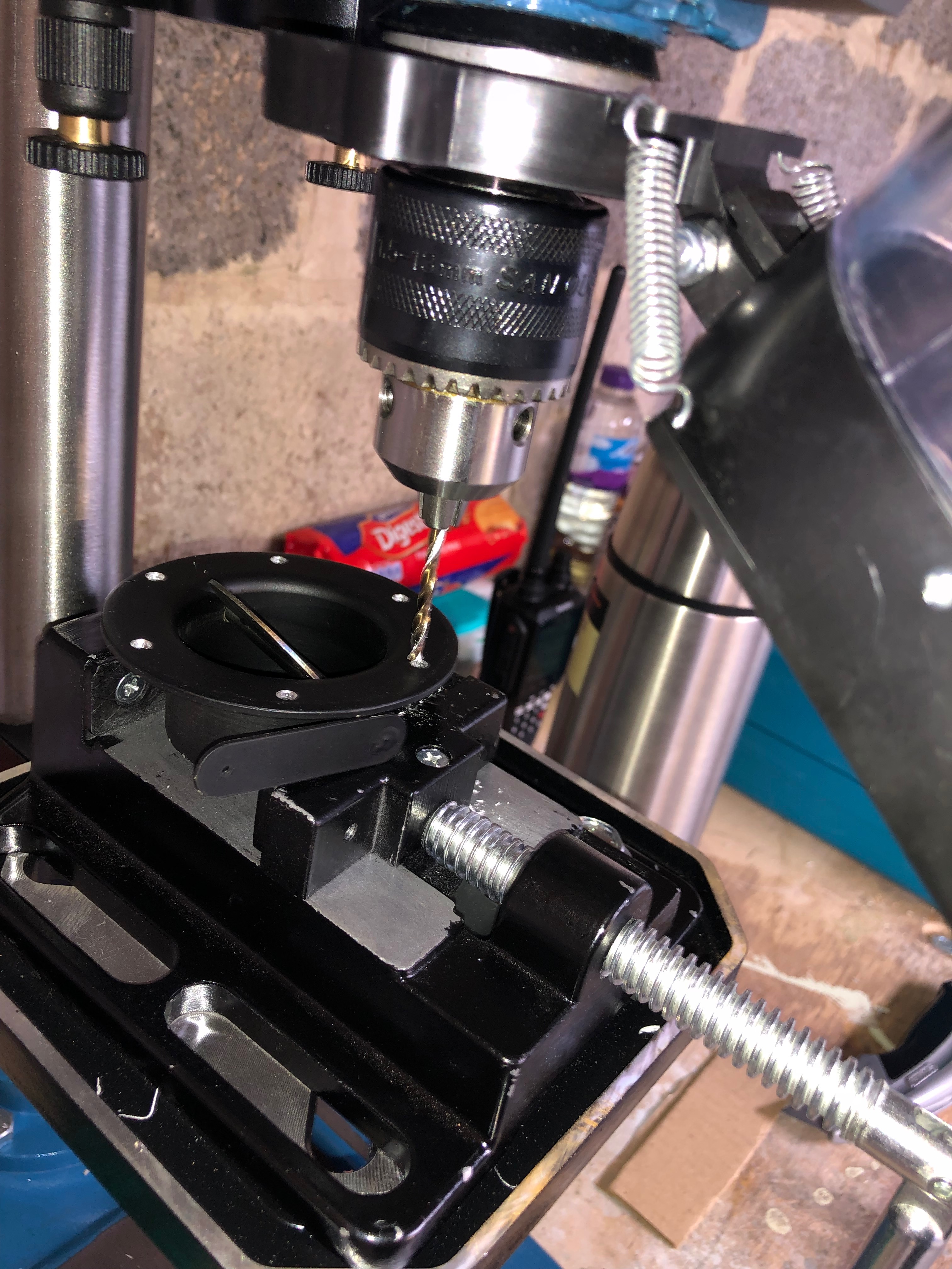
As the new pipes are manufactured by cutting and welding the insides should be checked for weld debris and cleaned.
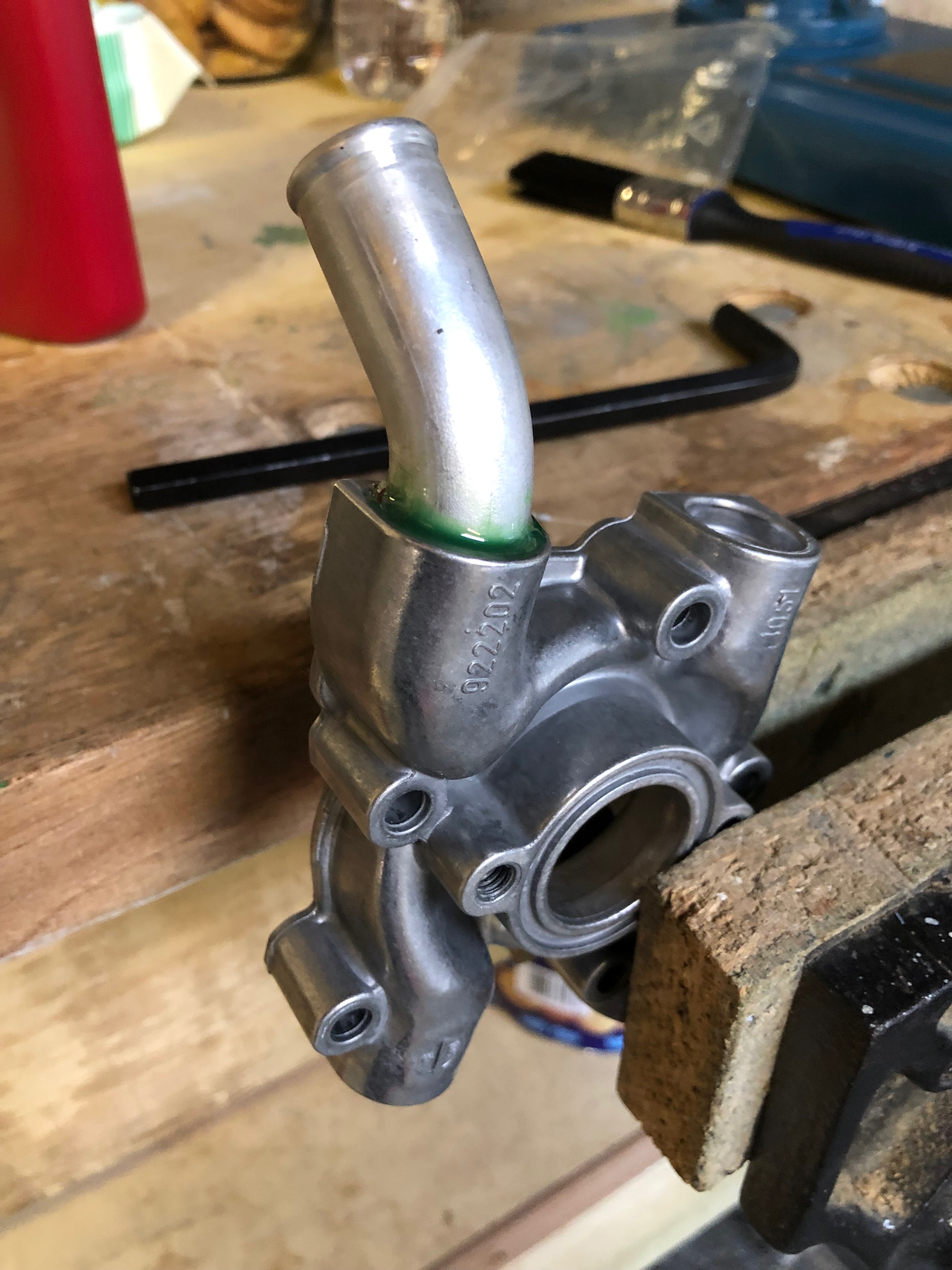
Loctite 620 is applied to the thread and the first of four pipes are refitted. The pump is offered up to the engine and the angle of the pipe is checked to ensure that it doesn’t foul the engine mount and that there is enough clearance to refit the water pump pipe .
All the pipes fitted and angled correctly and left to set overnight.
Again the engine is lowered overnight for peace of mind.
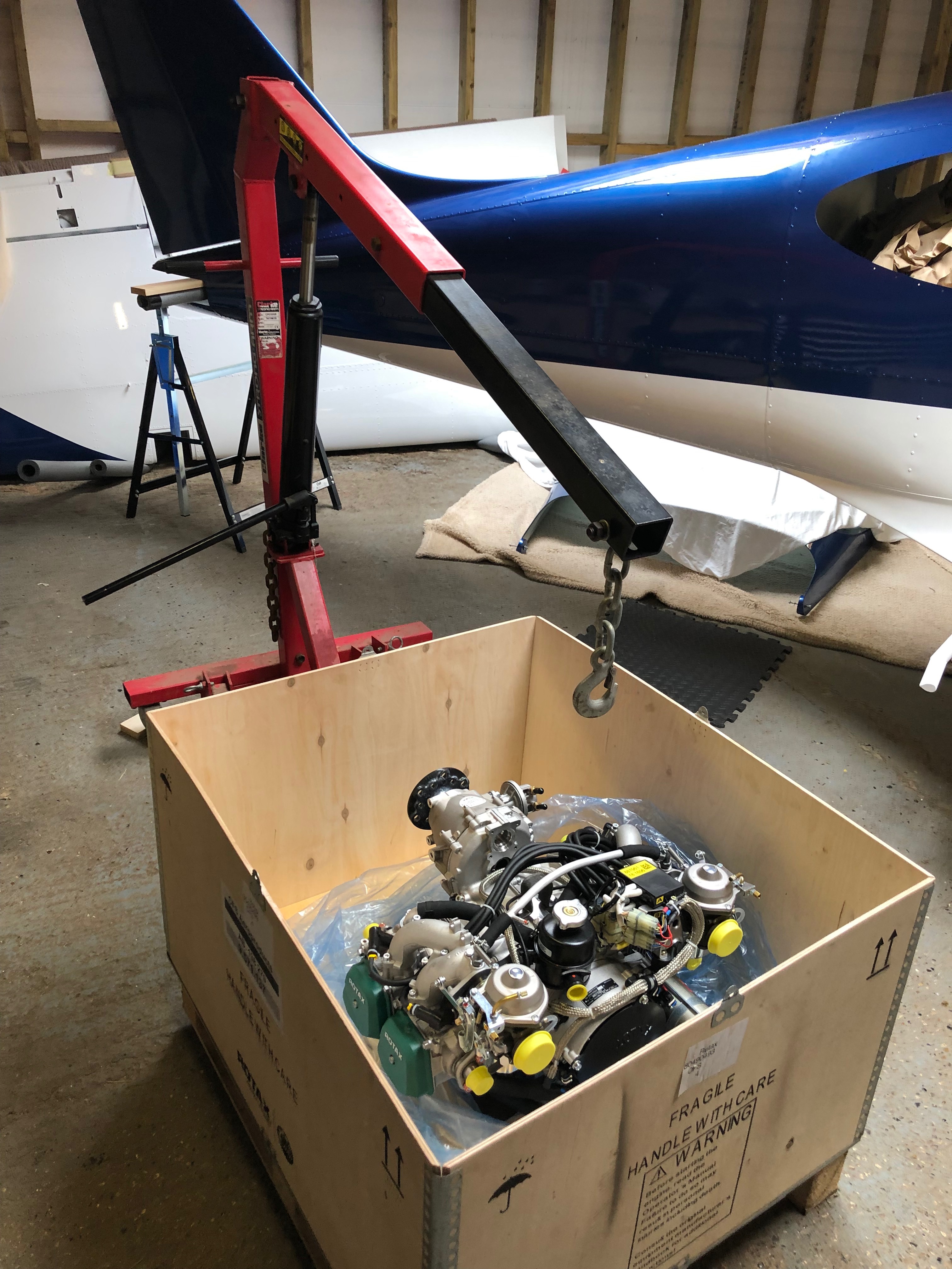
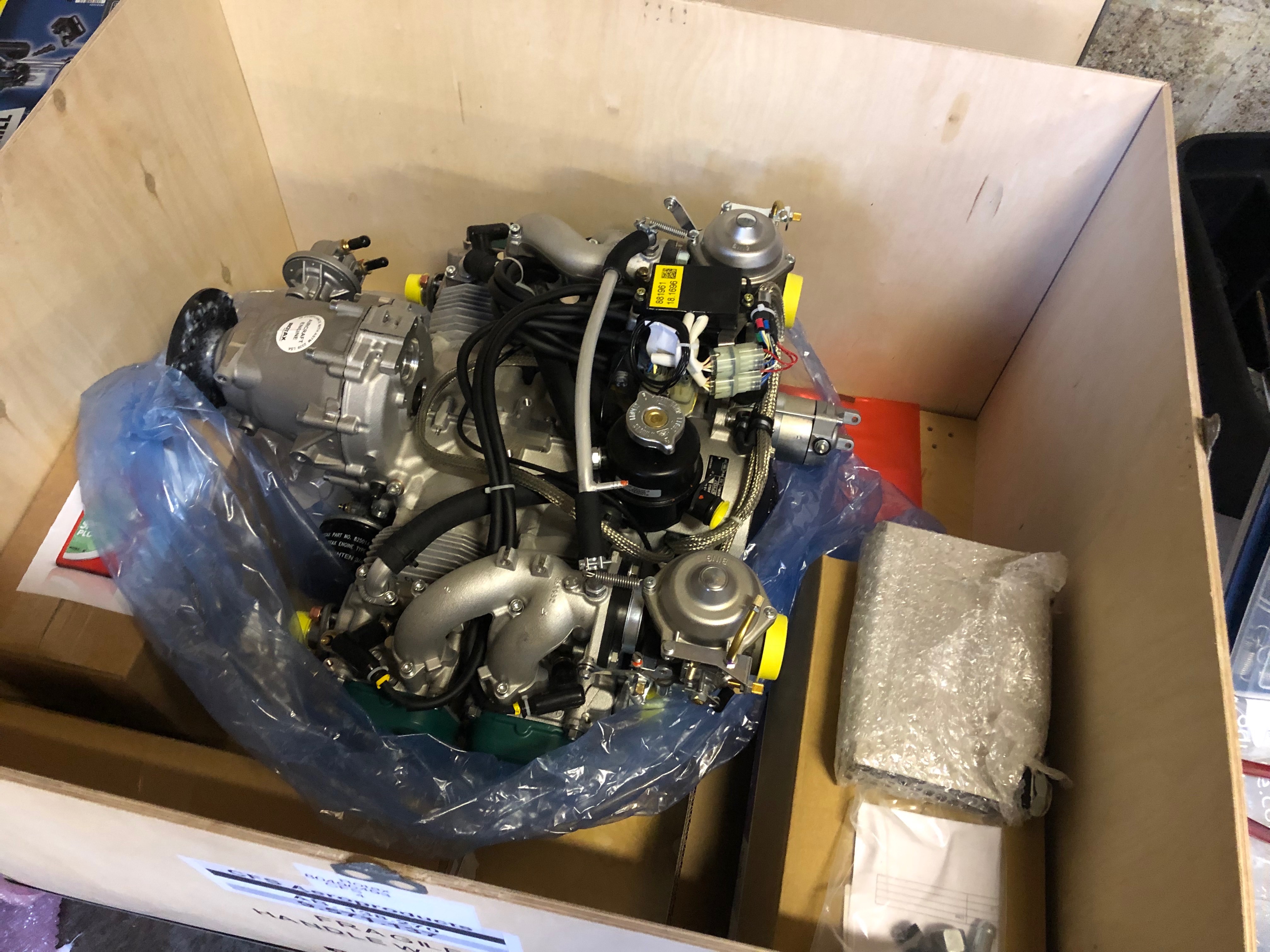
Time to lift the engine. Luckily there is an engine hoist onsite that belongs to Richard and he didn’t mind me using it.
Quite nervous about lifting the engine and and trusting the hoist and the lifting bracket that I made but it seems to be holding up ok.
As the Bristell uses its own engine mount two of the pump aluminimum pipes need to be repositioned and the other two need to be replaced with modified pipes that come with the kit.
So the pump needs to be removed.
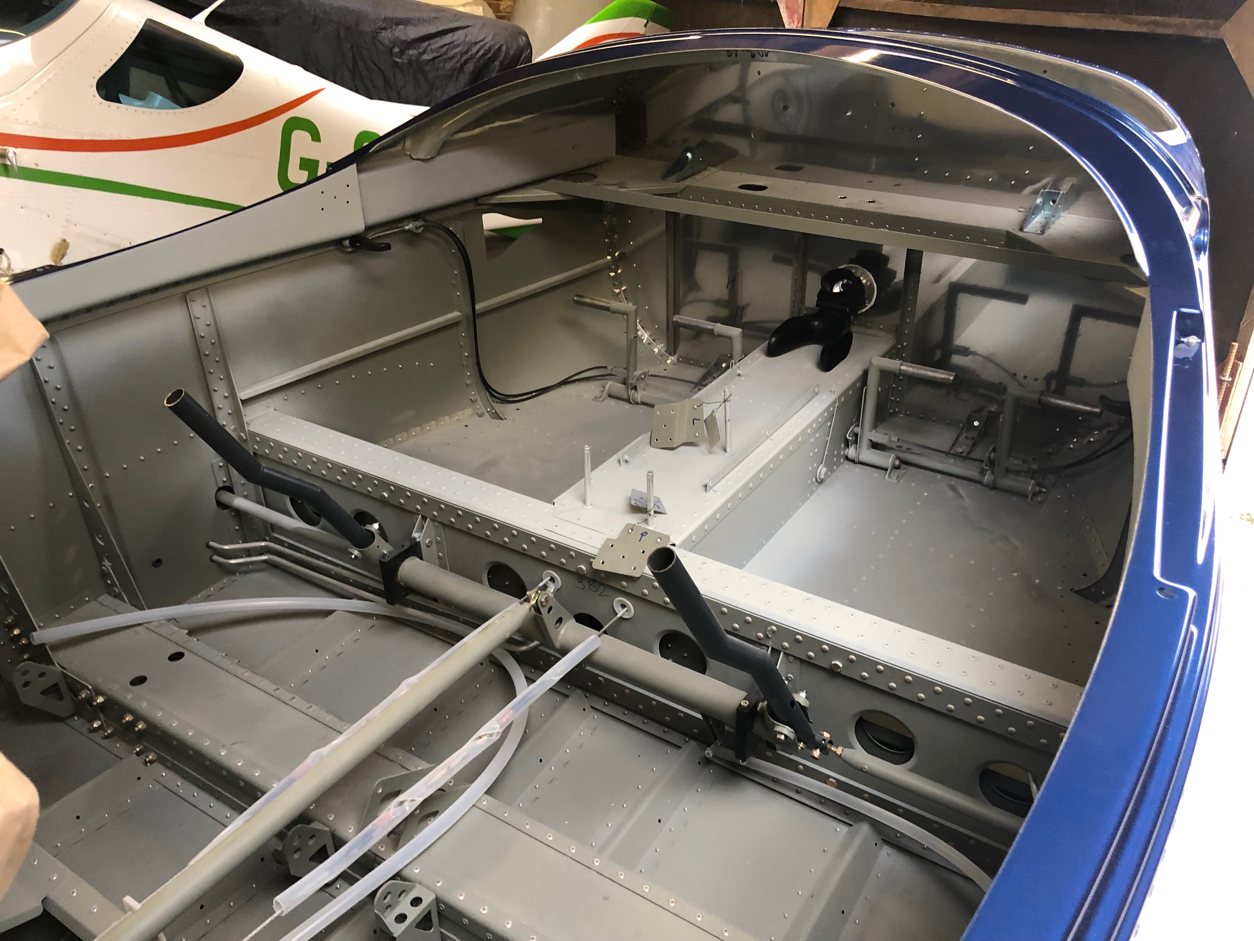
The engine mount needs to be fitted as it’s the only way that you can position the new water pump pipes. The mount is quite tight to fit and you need to make sure that you don’t catch any cables. The top right bolt needs to be removed as that becomes one of the engine mounting bolts that are fitted later.
As stated above, it’s a very tight fit so care must be taken to ensure that cables don’t get damaged. They will need to be protected before the engine goes into service.
The engine mount fitted. The water pump pipes need to be removed but I decided to think it through a bit more before carrying out the work tomorrow.
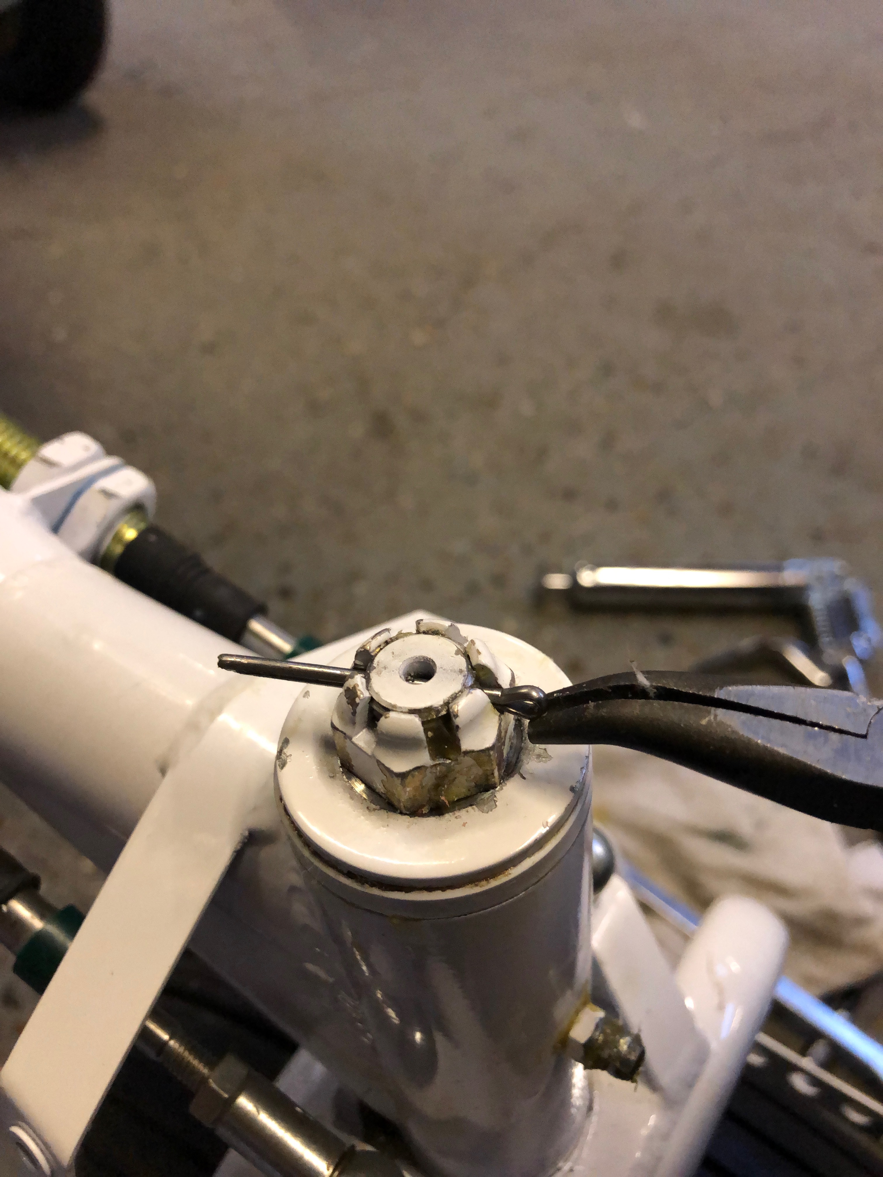
Now I have my grease gun I can fill the steering bearing with universal grease.
and then refit the castellated nut and fit a new split pin.
The other bearing that needs to be filled with grease is the nosebag pivot. It’s tricky to get to and once filled it’s tricky to remove the fitting from the grease nipple.
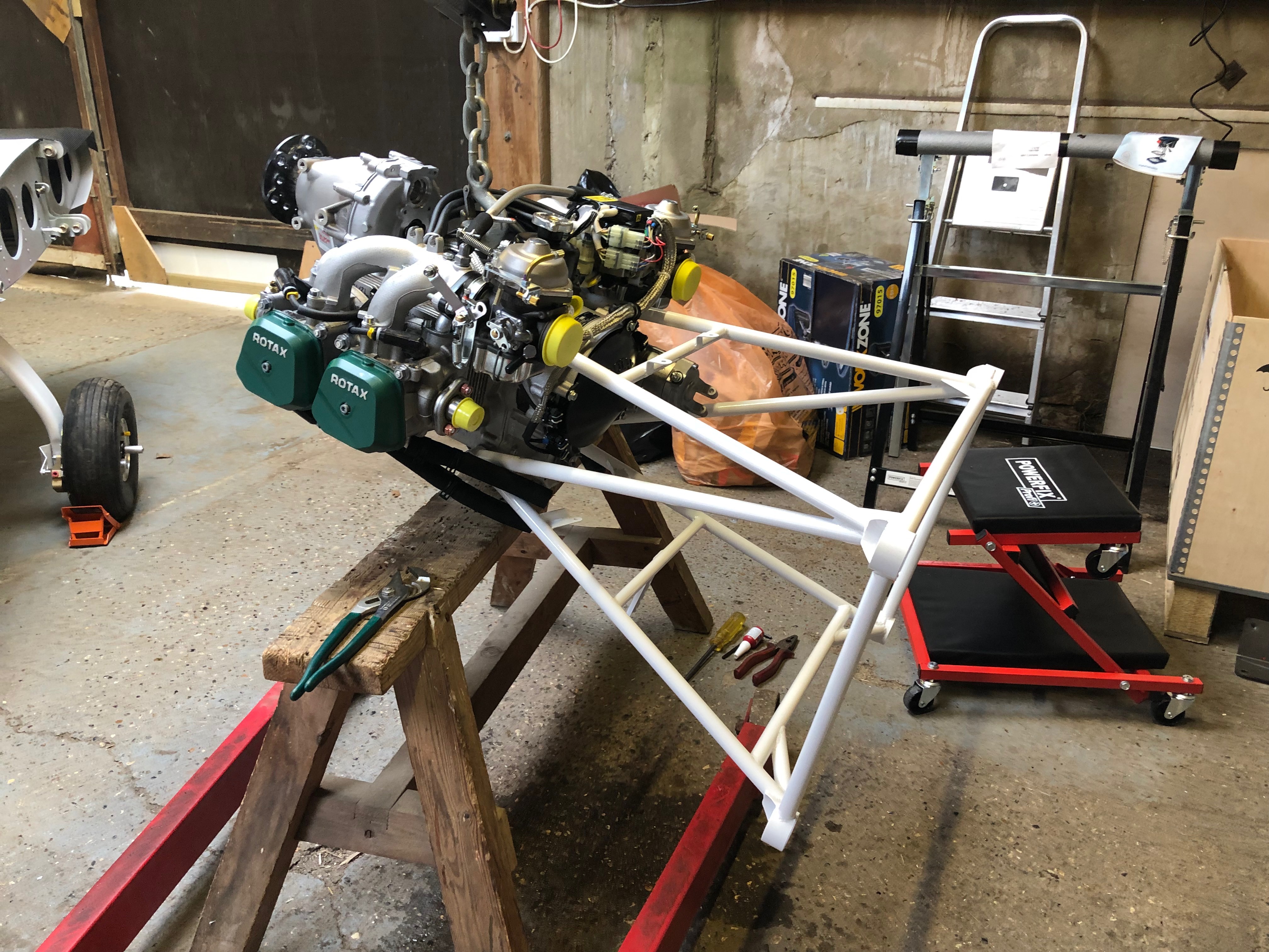
For peace of mind I’ve lowered the engine onto a beer crate and surrounded it with the packing that came with the engine so I can leave it overnight.