Well the best laid plans as they say… however with the weight and balance carried out yesterday meant my downfall today. Everything needed to be on the aircraft for it to be weighed however I forgot to ask Ian and Pete to help me take the canopy off. So I arrived to realise that I couldn’t do any of the things I had planned for today as I couldn’t get into the cockpit 😦 Usually people come and go during the day but no one turned up until around 3! So a very short day today.
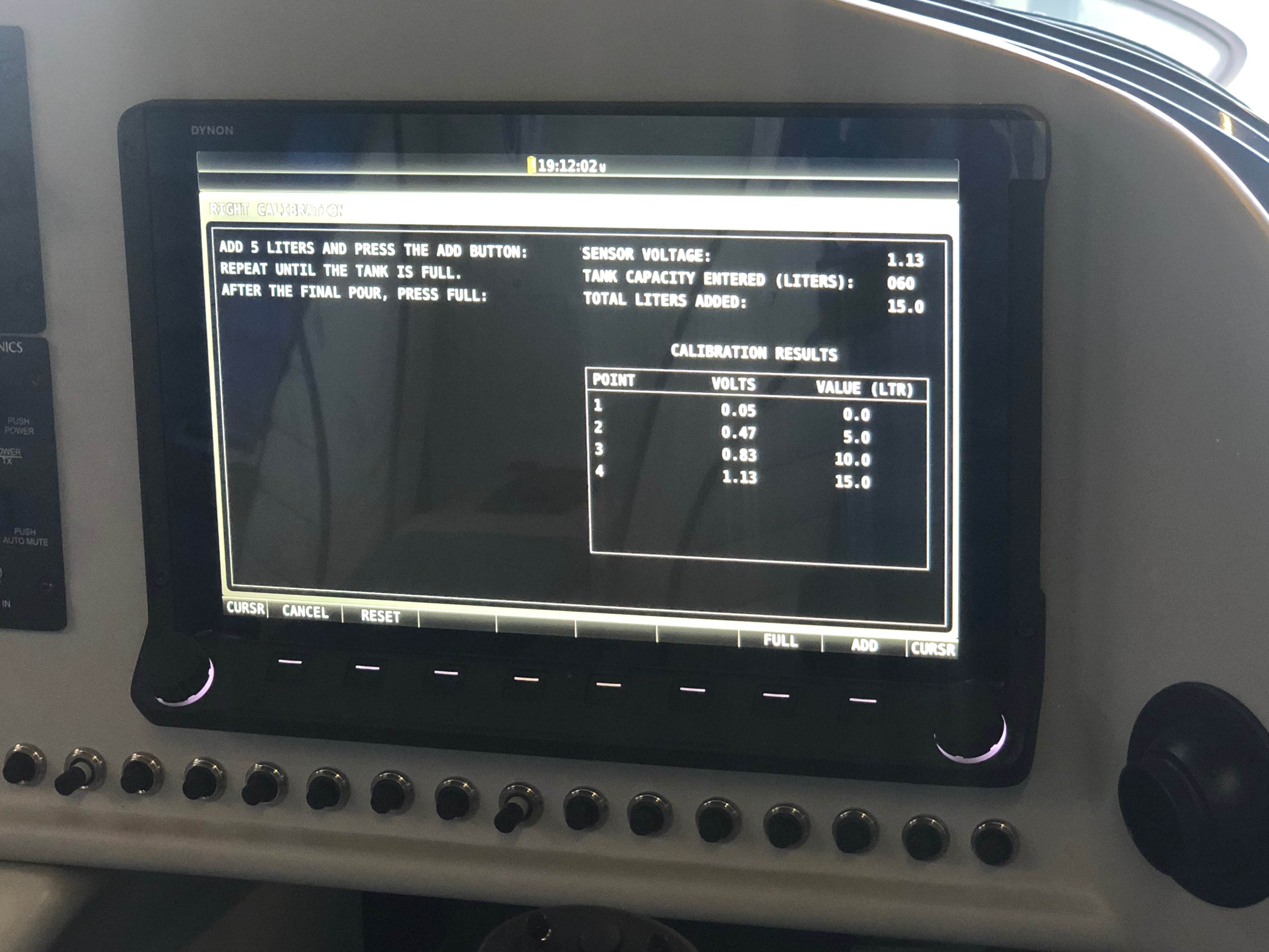
Up first was the calibration of the fuel tank sensors. This took longer than it should have done as I didn’t finish the process quite right on the first pass so needed to drain the tank and start again.
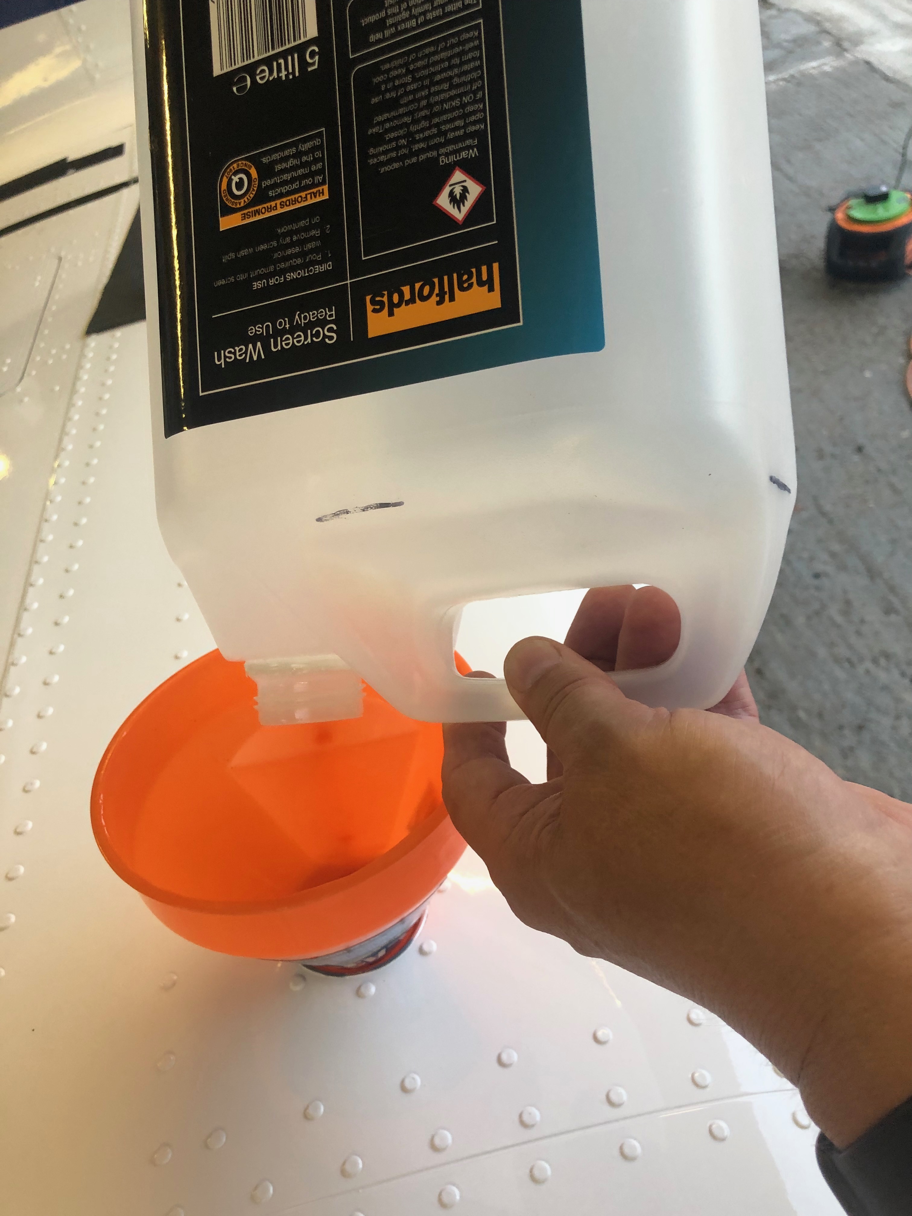
The calibration screen…I used a screen wash container that I had filled to the 5 litre mark and then filled that for each calibration point. The process was quite straightforward. Press start, pour in 5 litres of fuel, press ‘Add’ and repeat 12 times on the last fill press ‘Full’ except on the last fill you need to press ‘Add’ then press ‘Full’ Silly me got that wrong so…I had to drain out the tanks and start again! Eventually I finished it. The port wing will have to wait for tomorrow.
Getting close to finishing now so some small outstanding jobs to do including wiring starter solenoid protection, a stuck starter indicator connection and external level button on each stick top hat. I also trial fitted the registration and polished the fuselage ready to apply it.
I received the registration vinyls on Friday so today I need to ready the fuselage for them to be applied. Just a case to working out the best placing for them. Along the line of paintwork line or along the rivet line? that’s the question!I’ve bought a polishing machine to make the job easier with some G6 cutting liquid cutting compound. It takes a bit of getting used to using it but it makes a good job it. The paintwork needs to be de-greased before I can apply the registration letters.When I sent the aircraft for spraying they noticed that one rivet hadn’t been squeezed on the trailing edge of the wing. So Ian brought his rivet squeezers in with a special head for this type of rivet. A little more wiring to do. A diode is placed from the starter solenoid to earth to kill any spikes caused from the contacts releasing when starting the engine. Also I’ve wired up a contact on the Dynon screens to that will show a ‘stuck starter’ situation. I was a little worried that a higher voltage may find it’s way back to the EFIS so I’ve protected the connection with a diode to prevent spikes and a 1 amp fuse.
A lot to do today, as every day! When the delivery arrived I found that some of what I had ordered was out of stock. It’s not a big problem as there are lots of other jobs to do. So I’ll wire up the power side of the system and label, install and test the radio and transponder coax cable.
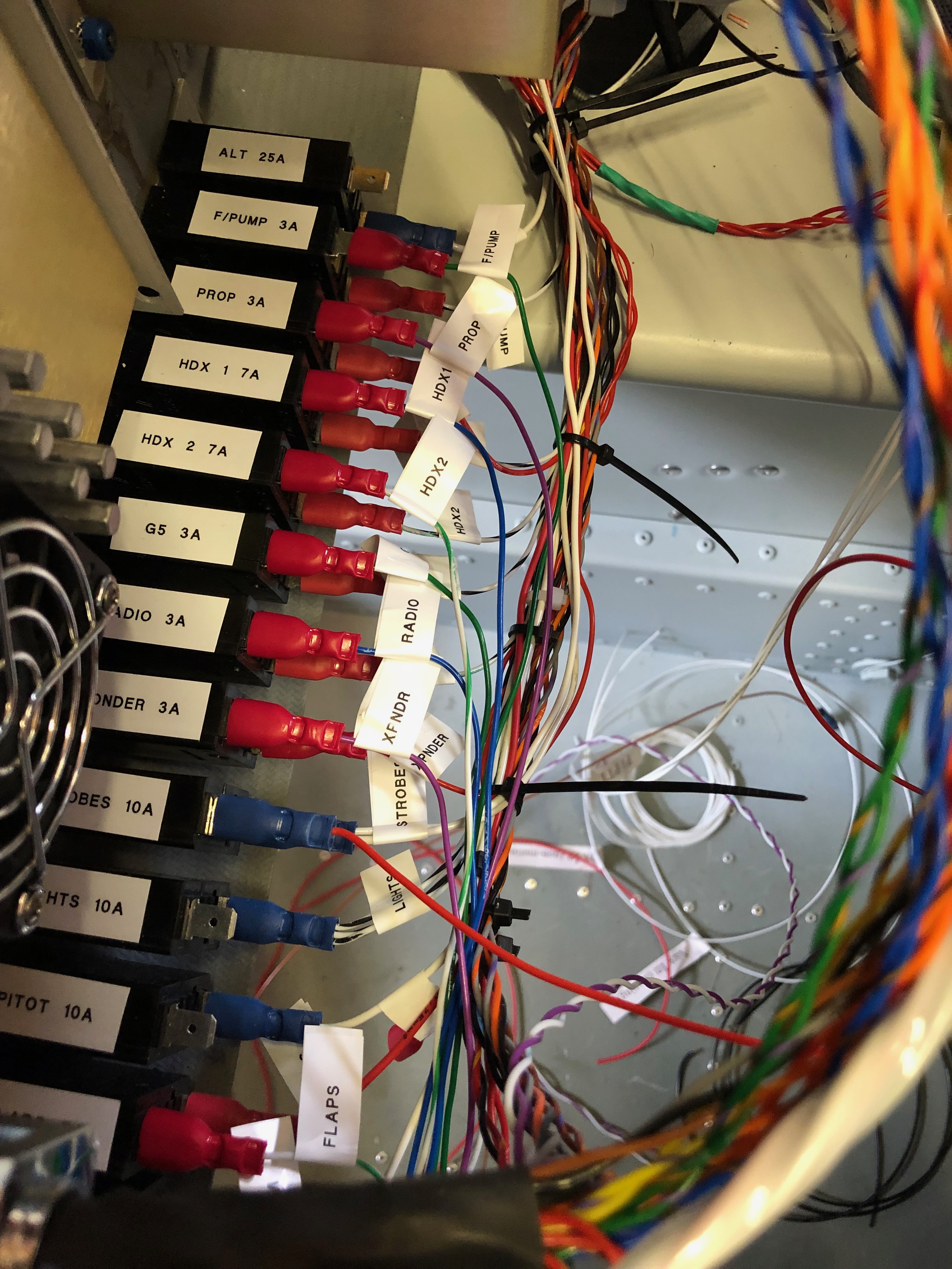
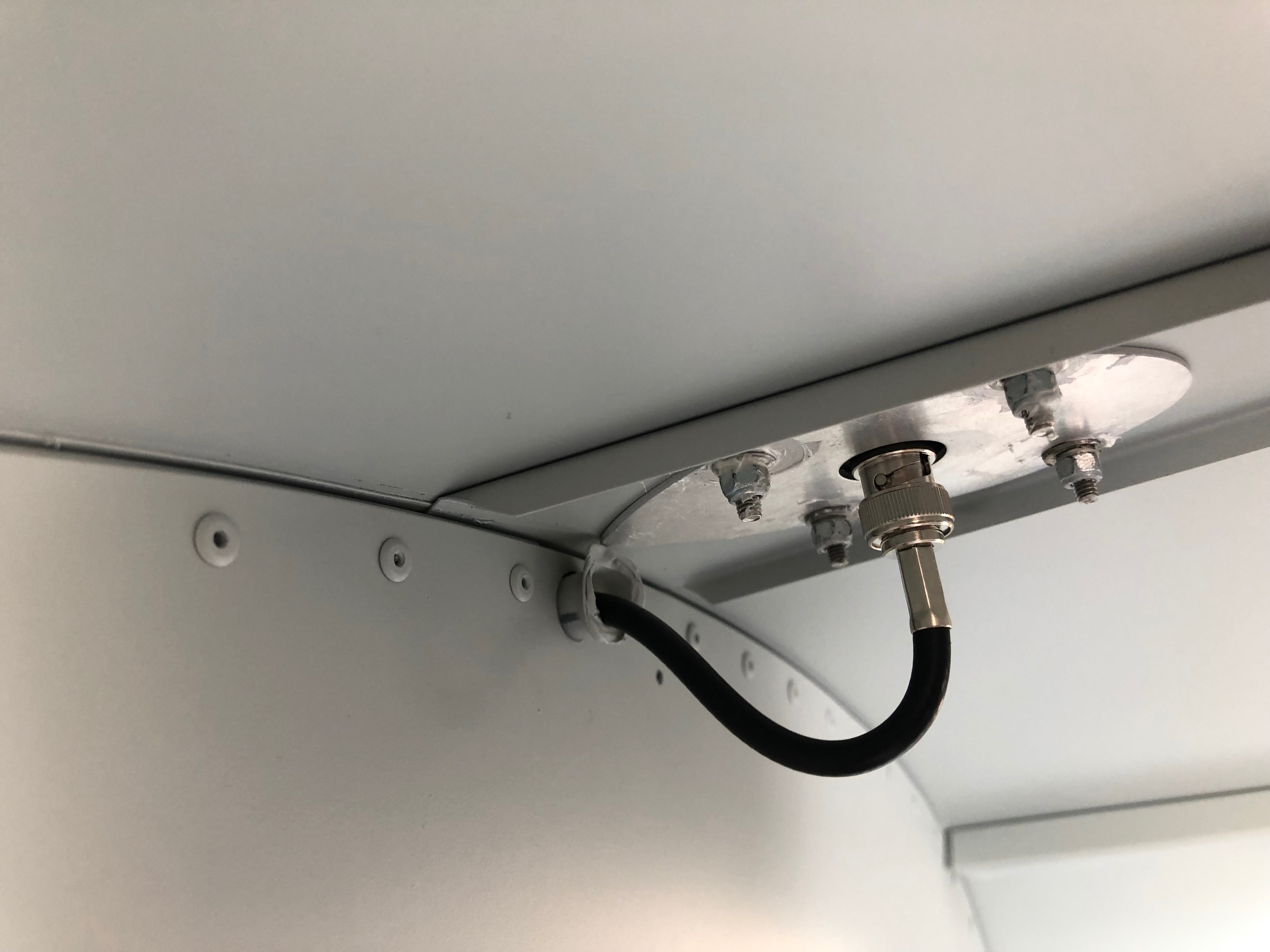
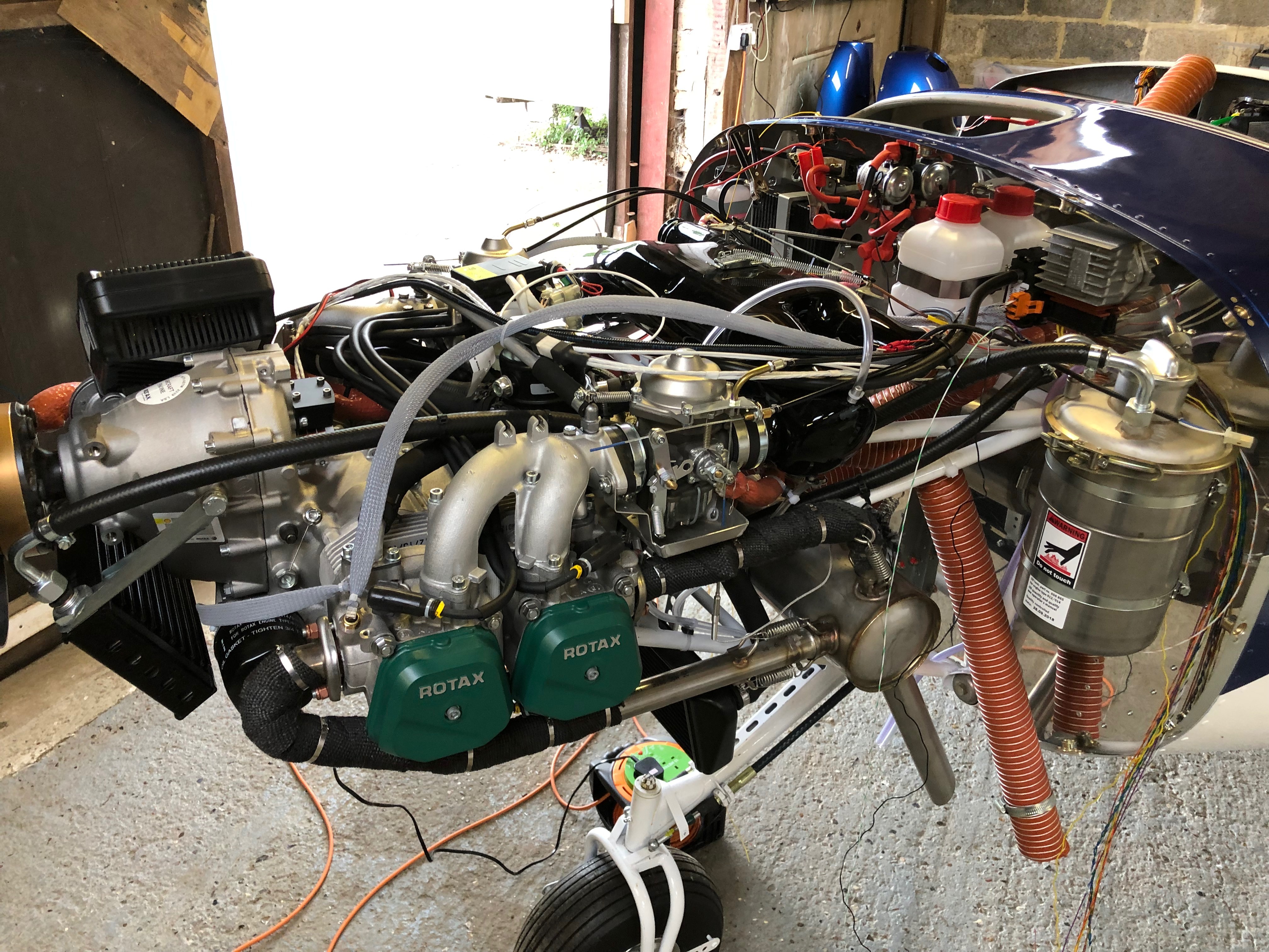
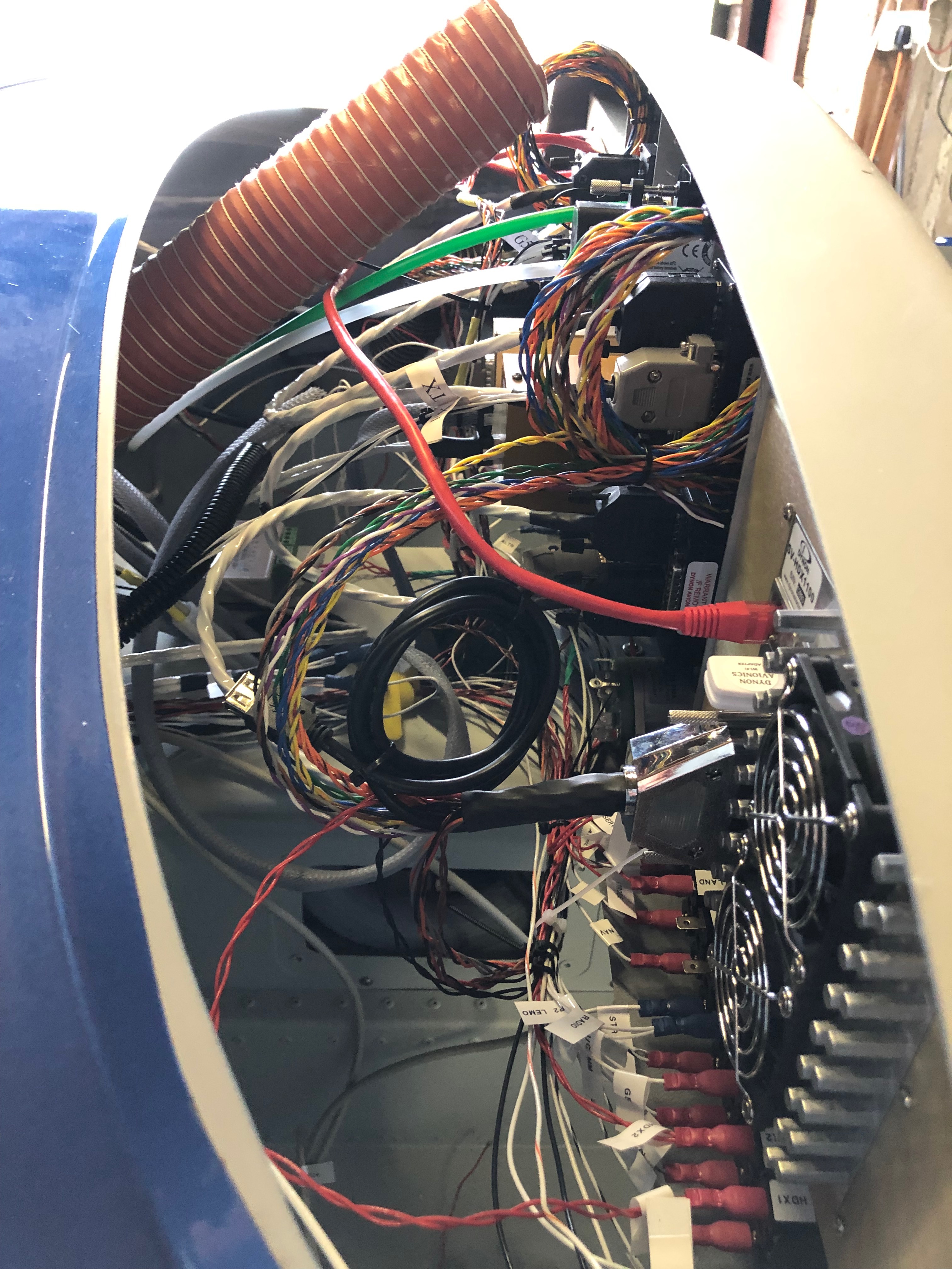
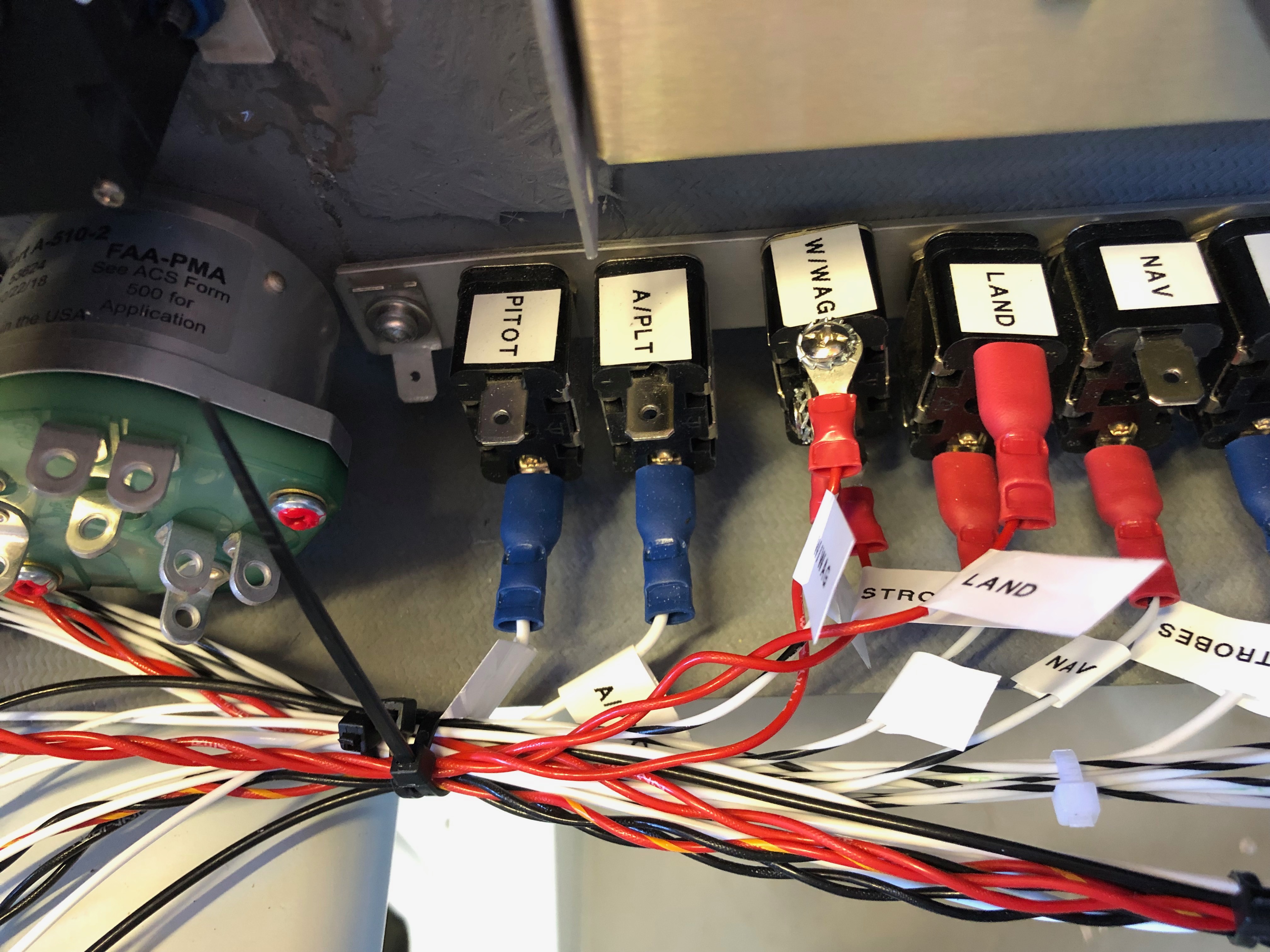
Time to wire up the power side of the electrical system. I’m reusing the wire that I have leftover from the other circuit wires that were trimmed back. There’s plenty to do the job although not a unified colour as long as they are labelled it will be ok.My new friend. A Dymo Label Manager 200 that I bought some years ago. It’s been invaluable and luckily I managed to get some label cartridges.The +ve bus with 11 of the circuits completed.The circuit breakers connected, some tidying will be required but it’s mostly complete.The complete panel powered up for the first time. The system shows a 7 amp power drain which is roughly what I had calculated.My DPD delivery was a day late but got delivered at 10am so I could get on with the wiring of the Transponder and Radio with the coax.The radio coax cable runs through conduit in the fuselage and is terminated with a TNC connector that I’ll do tomorrow.With all the cables protected with sleeving or conduit and secured in place I can fit the interior trim.The rear of the cabin. I’ve checked the radio/headset loom and it works fine so I need to mount the LEMO headset connectors and then I can fix the interior panels.Right side of engine. All the sensors are connected except the Tachometer, soft start module, magneto wires.Left side of engine. Looks a bit busy but with a bit od tidying it will look a bit neater. Quite pleased with the progress so far.
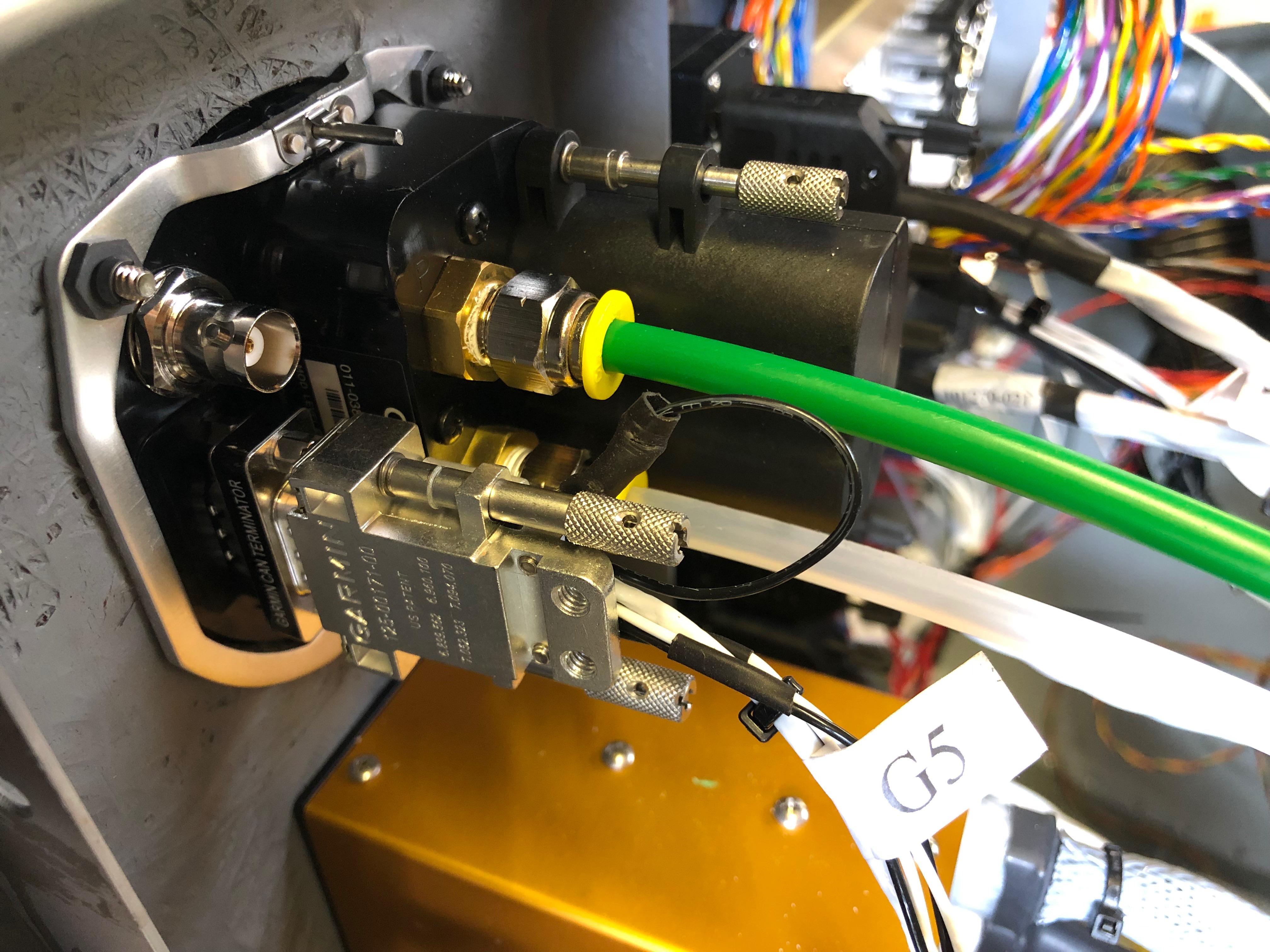
The wiring continues today with a couple of other items that I had put on the back burner. The tail strobe circuit was completed and wing strobe wiring started. One being the wiring of the extension wire for the elevator trim and the other the pressure plumbing for the G5.
After shimming the ADAHRS unit last night I replumbed the pressure system to make it tidier……allowing me complete the plumbing to the G5. I thought I’d start on the trim motor wiring but unfortunately DPD failed to deliver the wire I’d ordered so will do that another day! One of the jobs that I had been diverted from was the wiring up of the elevator trim so first thing is to solder them together and make sure that the colours match what I did for the aileron trim motor.
Music: The Pretenders – They were the support to Fleetwood Mac on Sunday at Wembley. I’d forgotten how good their music was!
Time for a short break from wiring but not for long before continuing the battle of the wires!
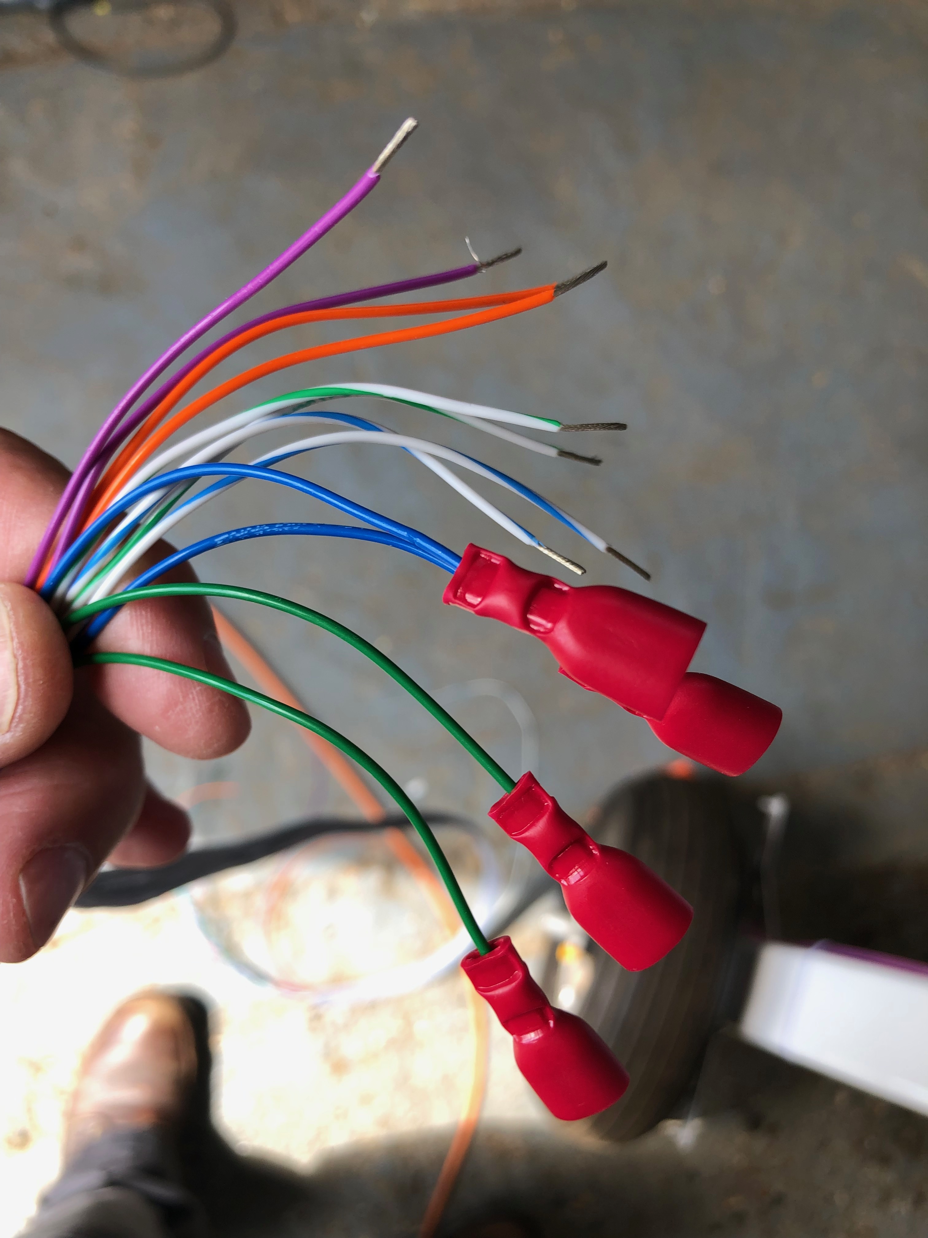
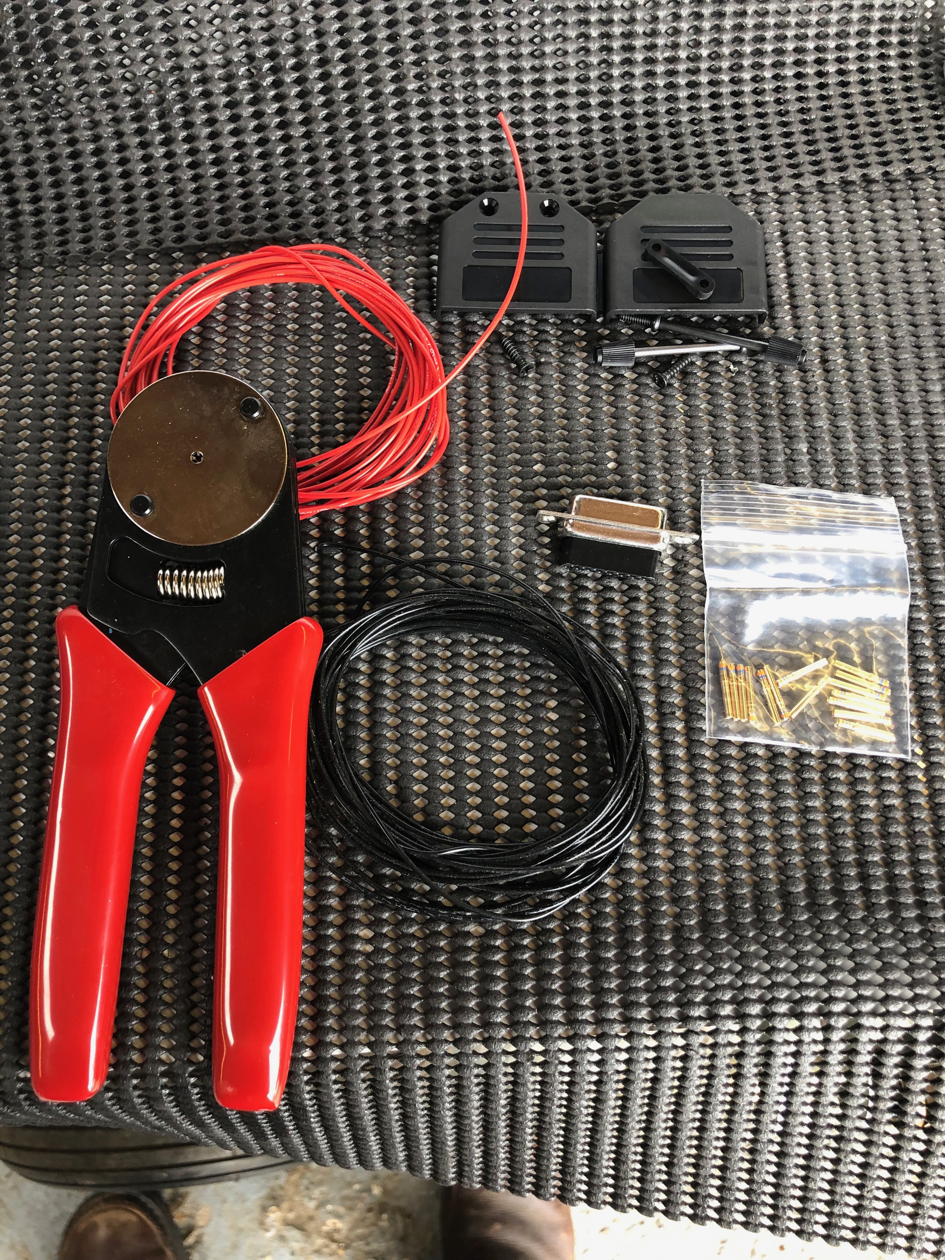
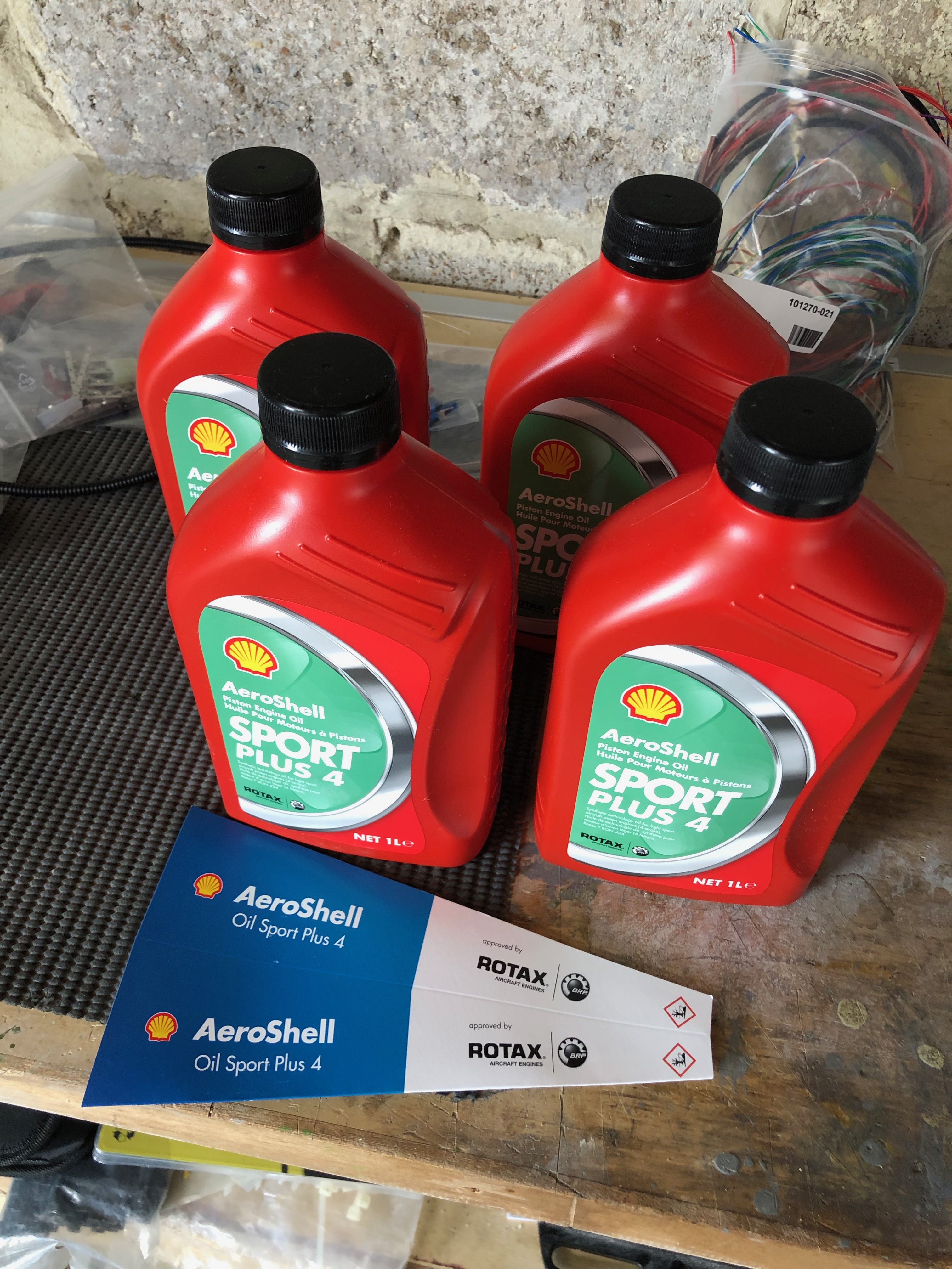
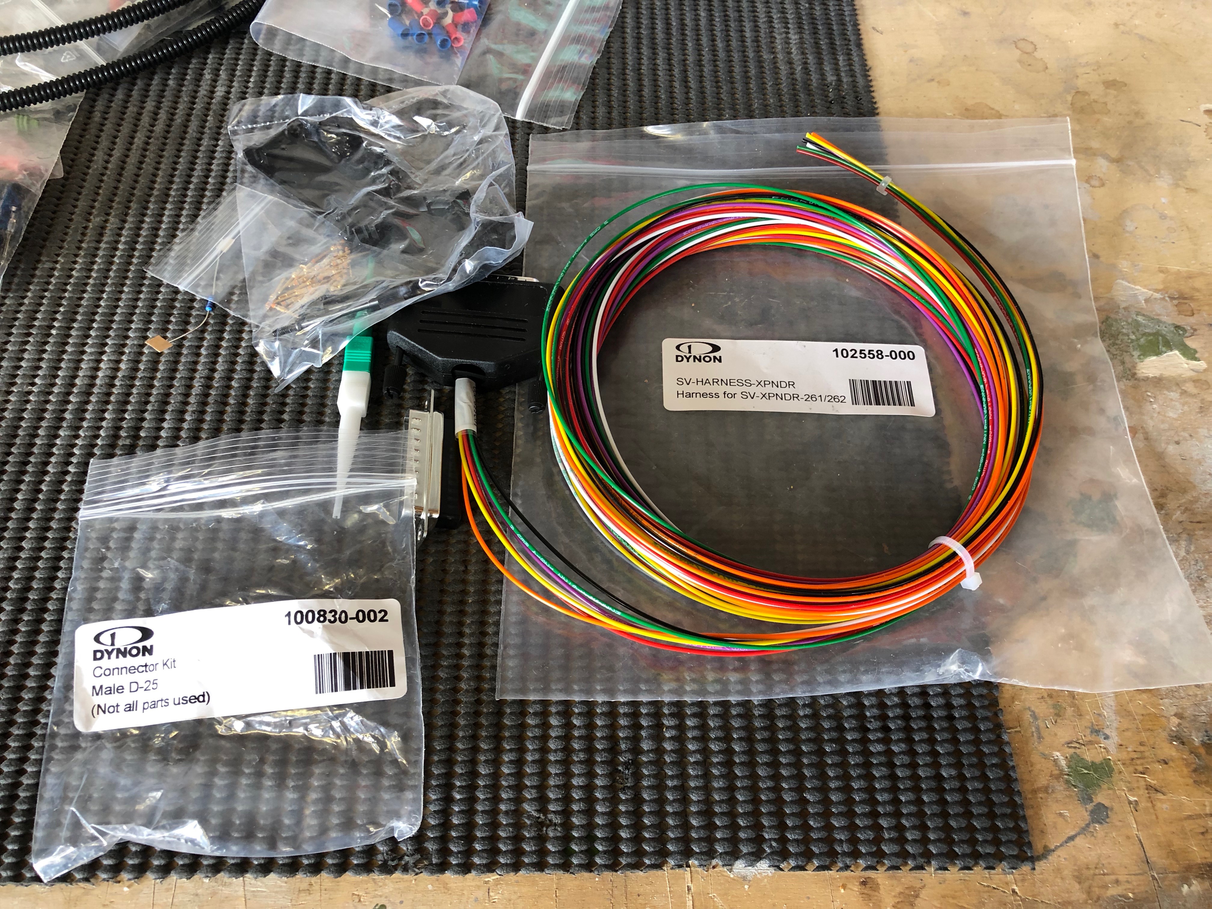
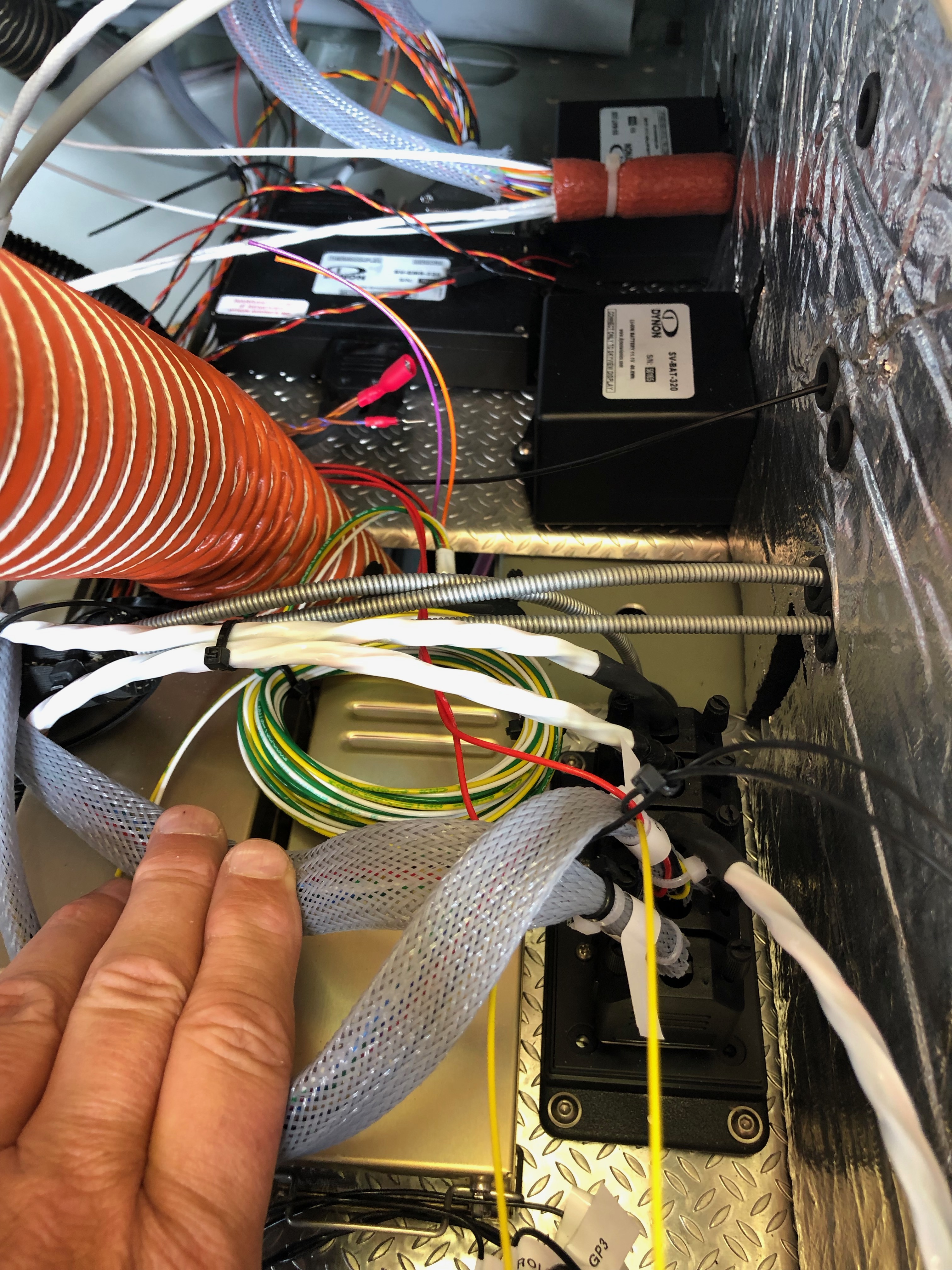
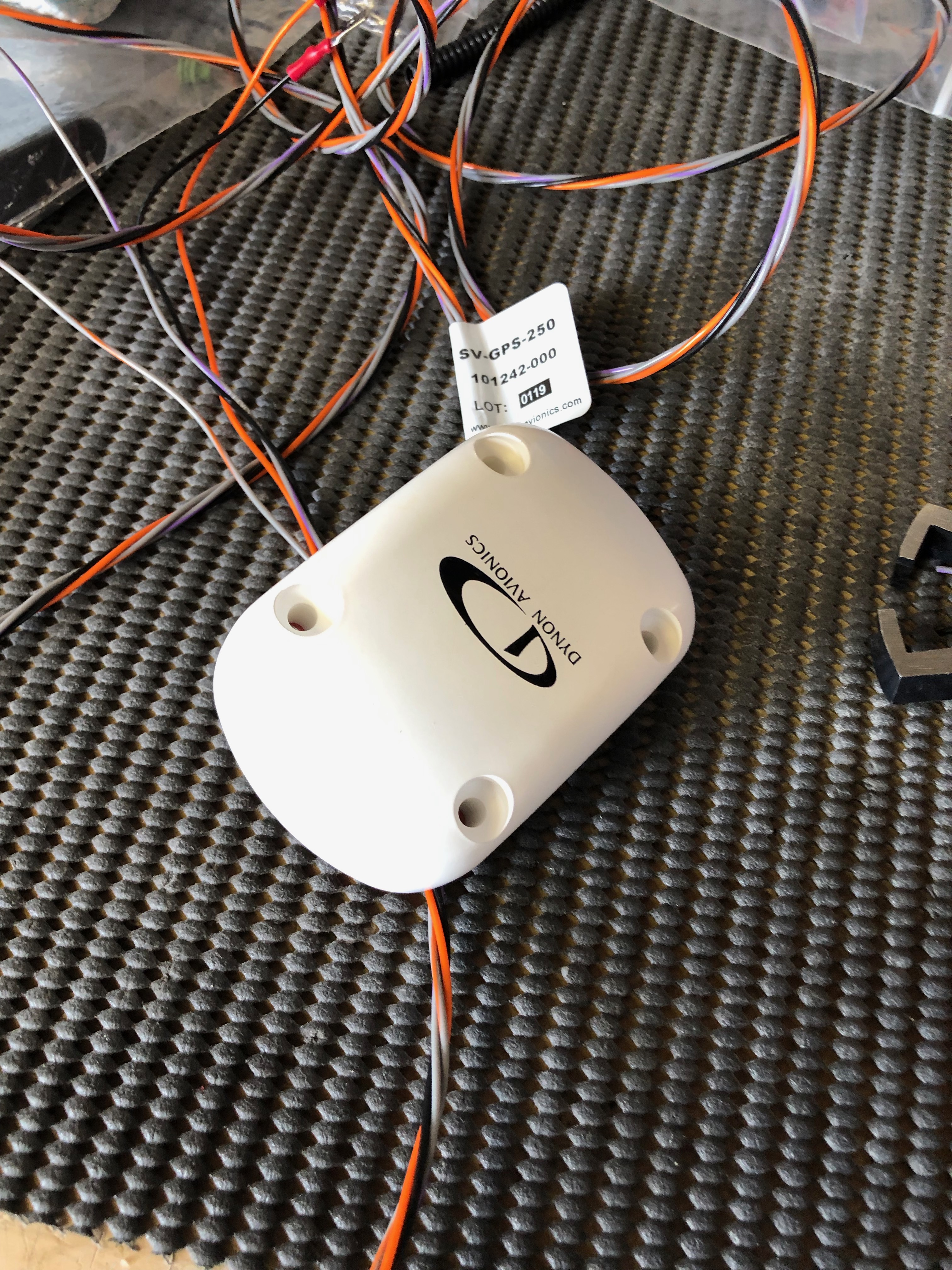
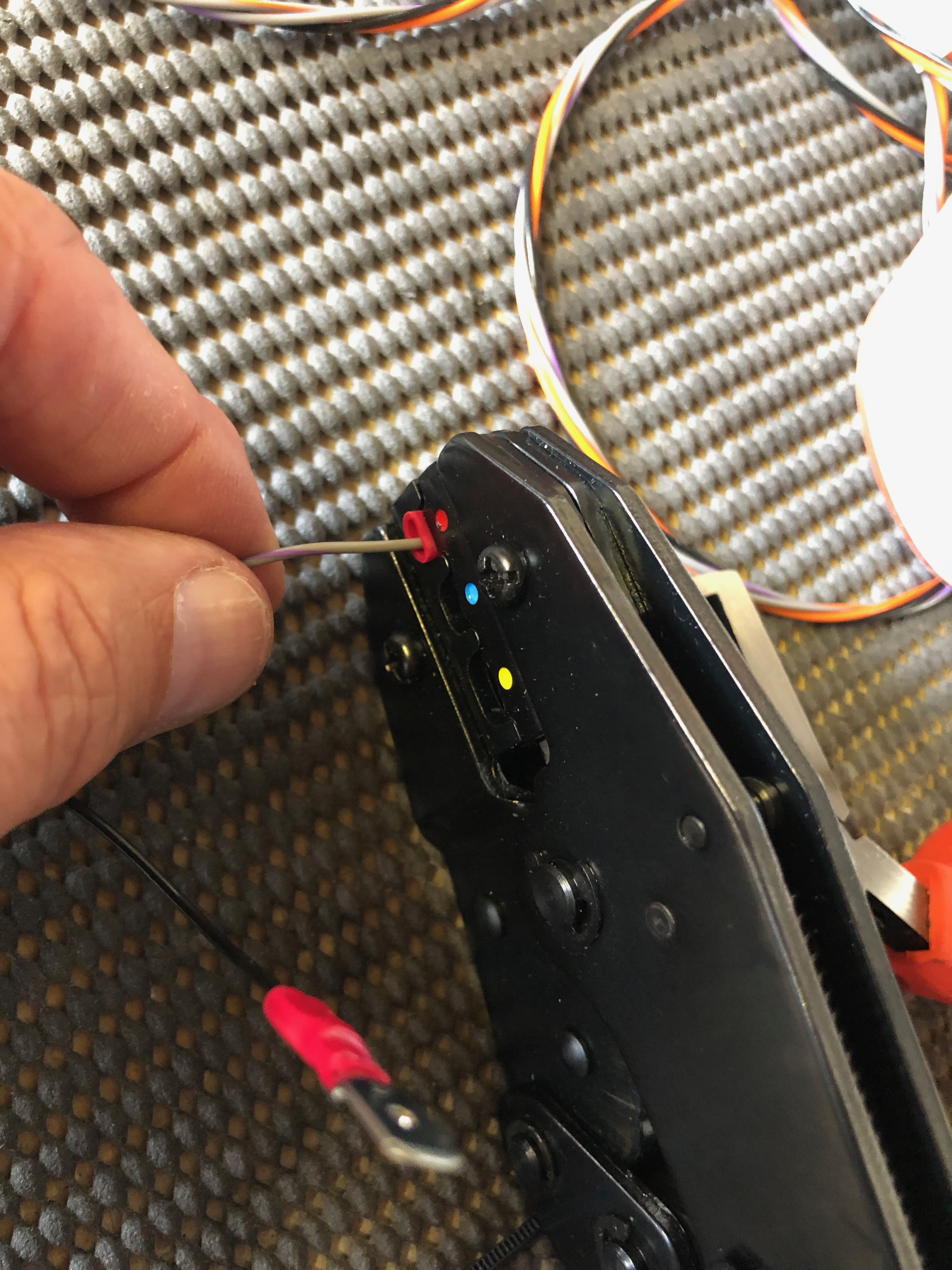
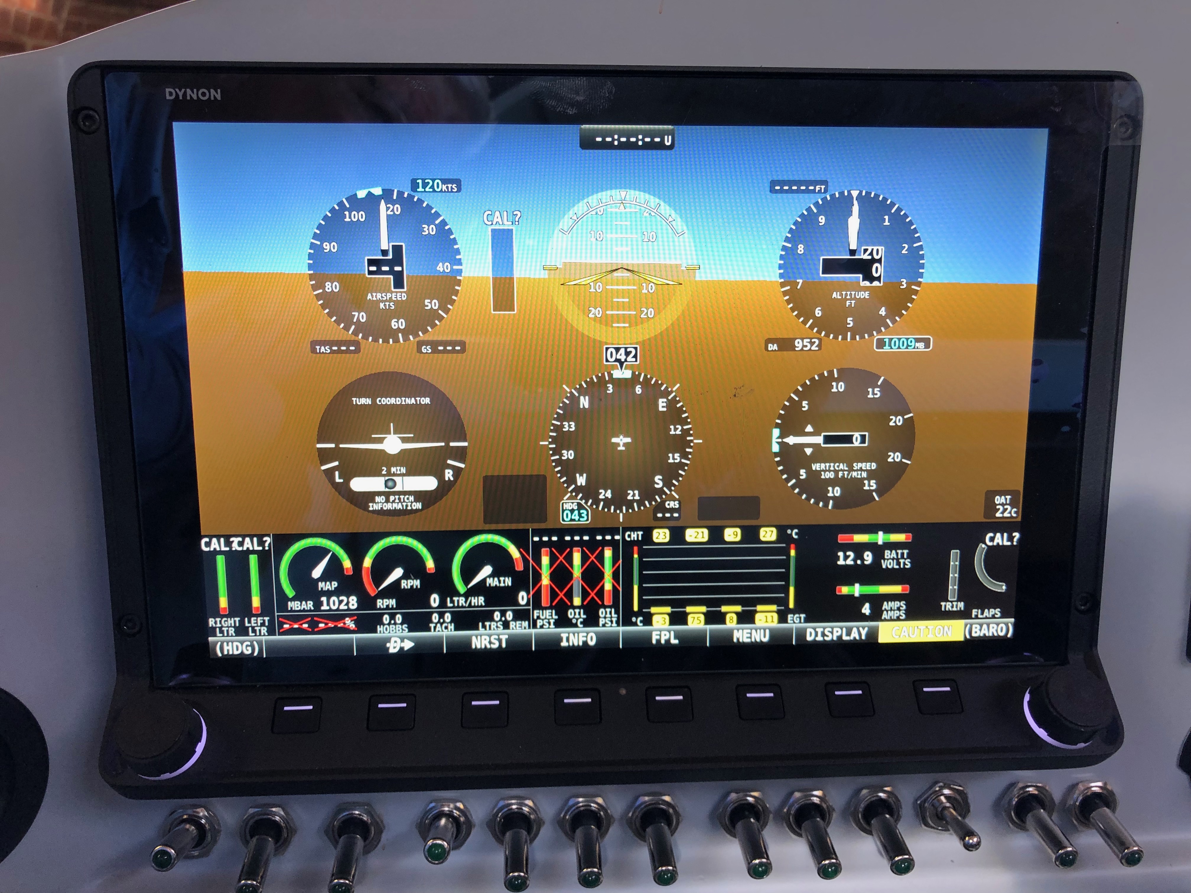
The Rotax engine comes with 4 litres of Aeroshell oil which I thought I’d add to the oil tank as a short break from wiring!I managed to get 3 litres in the tank but I will need to add more when the engine has been turned over a bit as there are a lot of empty oil pipes at the moment!After that very short break it’s back to wiring. This is the transponder loom which is a bit overkill for my needs. As you can see by the coil of wire there is a lot of unused wires but and a lot more has been trimmed from the length of the wires that are used! Once I had checked that it worked as expected I cut the unused wire off and covered the unterminated ends with heat shrink.Before adding a GPS receiver the SkyViews have no idea where they are in the UK, in fact they think they are in the USA! So I’ve taken the power and serial data leads from both SkyViews, spliced them and will connect them to the GPS. There’s a lot of cutting of wires and terminating them, mostly with fully insulated spade connectors using a special crimping tool.Once the GPS is connected a check is made on the connection to make sure it’s not reporting any errors and picking up satellite receivers ok..…and if by magic the SkyView now knows it’s in the UK! The system is reporting height and position correctly from my checks. If you look at the slip indicator you can see that its not in the middle and that’s because the ADAHRS isn’t quite level. There isn’t an adjustment that can be made to correct this so I’ll shim the unit.I’ve positioned the aircraft on a piece of level ground and I’ve shimmed the unit to make sure that it’s level and reporting correctly which it now is.
I decided to visit Air Expo at Booker yesterday but I can honestly say the show was a complete waste of my time. It was raining all day and a lot of the exhibitors had scaled down their stalls and some hadn’t turned up at all! I did buy a Sky Echo II there so I’ll see how that works when I finally get the plane flying.
The aim for today was to continue the wiring and connect a few of the sensors.
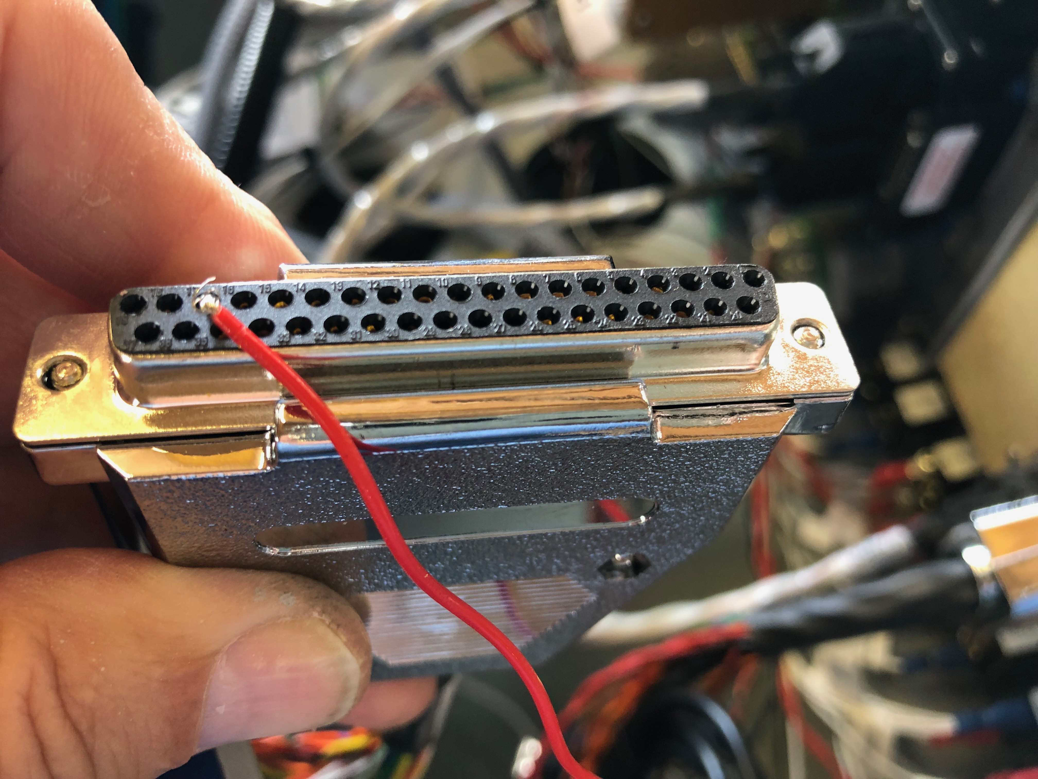
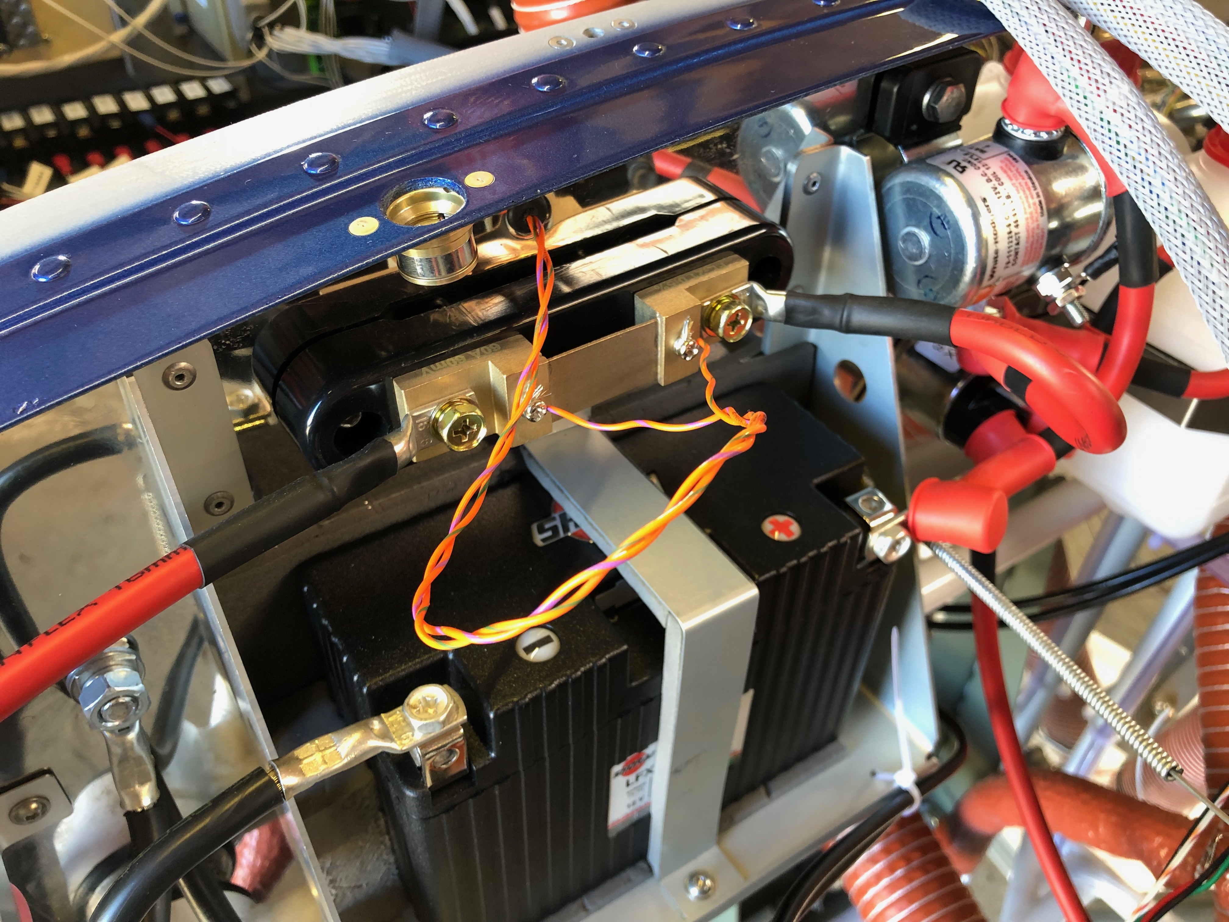
The EMS loom has a D37 that connects to all the various sensors around the aircraft. It’s good to check the pin out with a multimeter before connecting to any of the sensors. First up is the MAP sensor. The power and ground on this sensor can be shared with other sensors so I’ve broken out those pins to use for the the fuel pressure sensor.The system power load can be displayed on the SkyView by measuring the potential difference across a precise resistive load, in this case a Amp shunt. The wires connect to either side of the resister. To protect the SkyView from high currents a 1 amp fuse is connected inline which I’ve ordered and will be arriving Sunday so I’ll fit on Monday.The landing light controller that I bought from the States is wired up to a 3 position switch. I’ve designed the lights to be steady, wig wag and strobe. Hopefully it’ll work as designed.To get the light functions I need a 3 pole and 2 pole switch.The fuel pressure sensor is next but will be done on Monday now as I’ve run out of time.The HDX displaying in s ‘6 pack’ mode but you can see some of the sensors working correctly including the MAP, voltmeter and ammeter readings.
A number of jobs planned for today. Complete the engine NACA ducting, install the clevis pins to the carb heat control and cabin heater, install the fuel pressure sensor, install the engine intake air box, install the MAP sensor pipe, adjust and set the cowl quick release fasteners and install the control stick torque supports.
The fuel sensor and adapter were left to set with Loctite 577 overnight so can now be fitted to the fuel hose that I had added for it.
The hose is secured with a hose clamp and fire sleeve is added which is secured in place with locking wire.
The sensor is secured against movement and vibration with a stand-off.
These are the clevis fittings that are used on the carb heat, cabin heater, screen de-mist and park brake.
Now the sealant is set, the air box is mounted on a couple of brackets off the engine mount. It’s secured with a couple of Nyloc nuts underneath. Two short pieces of sturdy rubber hose are fitted over the carburettor inlets and the air box and provide a flexible joint between them.
They are secured in place with jubilee clips.
The SCAT ducting is secured in place with jubilee clips to the air box intake and the starboard lower cowl side NACA duct.
The ducting to the port NACA duct is run to the rear of the exhaust and then into the centre inlet on the heat exchanger, secured with jubilee clips and held in position with a couple of tie wraps.
Port NACA duct.
Even with all the space that the Bristell has It can get a bit tight with all the hoses that are required.
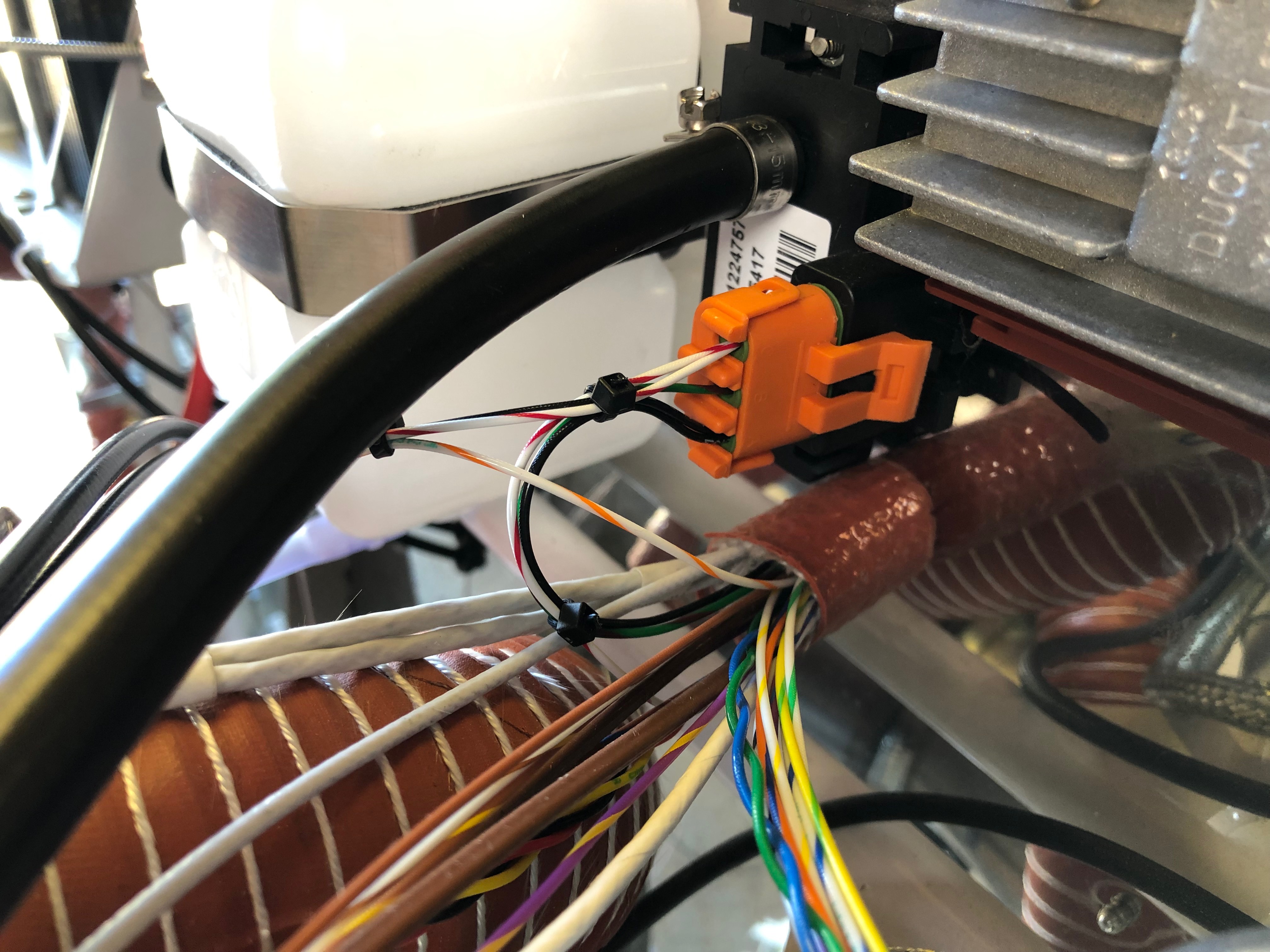
The MAP sensor has already been mounted so just needs a pipe to be run and of course some wiring at a later stage…
I’ve used 5.6mm ID R9 fuel hose between the carburettor balance pipe and the MAP sensor.
The quick release fittings on the fuselage have been riveted in place and now require them to be adjusted and set. First thing is to screw them in…
until they are flush with the cowl.
Once adjusted the pin can be pulled that sets them into position.
They are released by a quarter turn of the Philips screw and the fitting stays set in place.
I still need to repeat the process for the top cowl and the oil inspection cover. Ian will be installing the fittings during next week. Unfortunately the rivets need to be ‘squeezed’ and I don’t have the tool to do it.
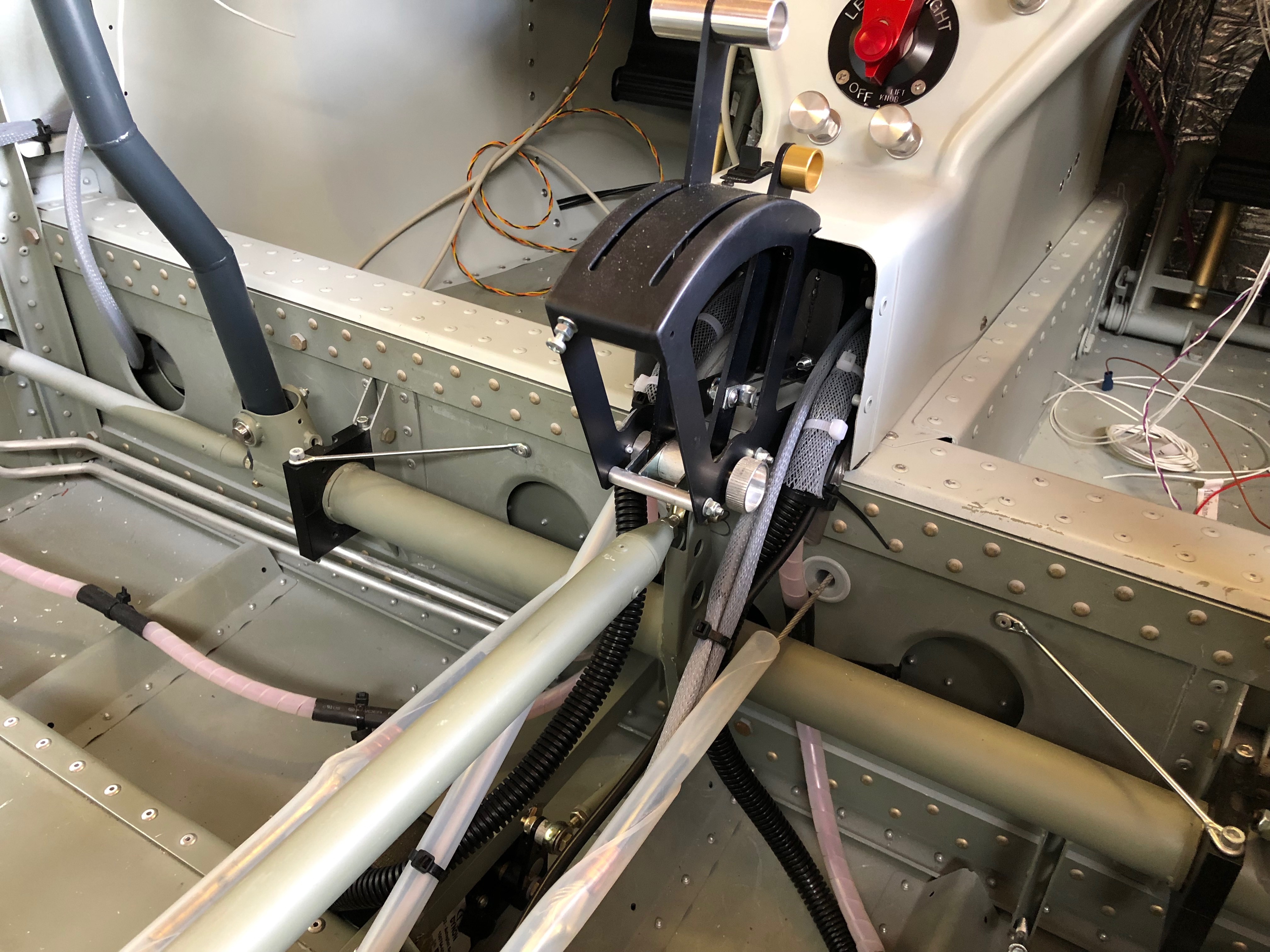
Now I’ve picked up the control stick torque arms I can start work on the control sticks.
The fittings need to be checked and secured although they will need to be adjusted when the wings are fitted to centralise them, set the limit screws and check aileron deflection are correct.
The torque arm is attached at one end using the bolt from the control stick bearing.
The other end is secured with a 4 x 15mm rivet.
Both torque support arms fitted, completing a fairly productive day.
I’m still not 100% sure on the layout of the screens and associated control panels so I thought it would be good to add the pilot seat so I could check different layouts.
Once the seats were installed I could sit in the aircraft as I would normally fly it. The panel here has most of the bits I need but is missing the flap switch, some warning lights and the air vents.
I’ve stuck the pictures on using glue dots that allow me to move the pictures about. I can then do a ‘touch’ test on the layout to see what works best.
Now I’ve received the water thermostat I can finish the water system, install the EGT sensors and complete the exhaust system.
Thermostat, hoses & clips for install.
The thermostat is fitted behind the expansion tank.
The hoses are attached…
and the radiator bottom support bracket is installed…
Once the radiator is fully installed I can check the cowls fit properly.
As you can see there is some trimming that needs to be carried out to make sure the cowl doesn’t foul the radiator.
Looks ok from the front.
The exhaust seems to clear the cowl however another check will be made before final assembly. The gascolator is located on the opposite side to the exhaust pipe and requires a hole to be drilled which will enable fuel checks to be carried out before flight.
The installed thermostat with just a ‘stand off’ to be fitted to make sure it doesn’t rub against the adjacent engine mount.
Now the cowl fitting has proven All the clips are fitted – job done.
I purchased a Kavlico EMS kit so the EGT sensors need to be installed.
A 3.2mm hole needs to be drilled in the rear exhaust downpipes 4″ from the flange.
Once the hole is drilled and sensor fitted it is held in place with the supplied, modified jubilee clip. The sensor has a ‘collar’ that ensures that the hole is sealed.
The downpipes are re-fitted and re-wrapped, securing in place with stainless steel ties.
To ensure the springs don’t fall and cause a runway hazard if they fail in service they are wire locked. Tomorrow I will fill the centres of the springs with heat resistant silicone which reduces any resonance from the springs.
A few smaller jobs, including exhaust wrapping, sensor fitting and cable oiling ahead of fitting the water thermostat that I finally received today.
The landing lights come with a couple of spade connectors that need to be crimped on…
and then slipped into the connector block. I’ll need to do the same thing when I come to install the LEDs into the wing.
The MAP sensor is fitted to the firewall in a suitable position making sure that the plug don’t foul one another.
The space between the water bottle and regulator seems to work well.
The front exhaust pipes covered in exhaust wrap and secured in place with stainless steel ties.
There’s several cables that need to be installed later in the build. Unlike the throttle cables these aren’t lined so require some lubrication.
Received at last! Good ol’ Parcel Force have had this since the 5th March but never left a card. It’s lucky I asked for an update on delivery from Silent Hektik otherwise I’d still be waiting. This is the 3rd time Parcel Force have completely screwed up on a delivery to me – I will never use them again!
Following the build of my Bristell NG5 Kit No. 382 Registration G-MLSY