Now I’ve received the water thermostat I can finish the water system, install the EGT sensors and complete the exhaust system.
Thermostat, hoses & clips for install.
The thermostat is fitted behind the expansion tank.
The hoses are attached…
and the radiator bottom support bracket is installed…
Once the radiator is fully installed I can check the cowls fit properly.
As you can see there is some trimming that needs to be carried out to make sure the cowl doesn’t foul the radiator.
Looks ok from the front.
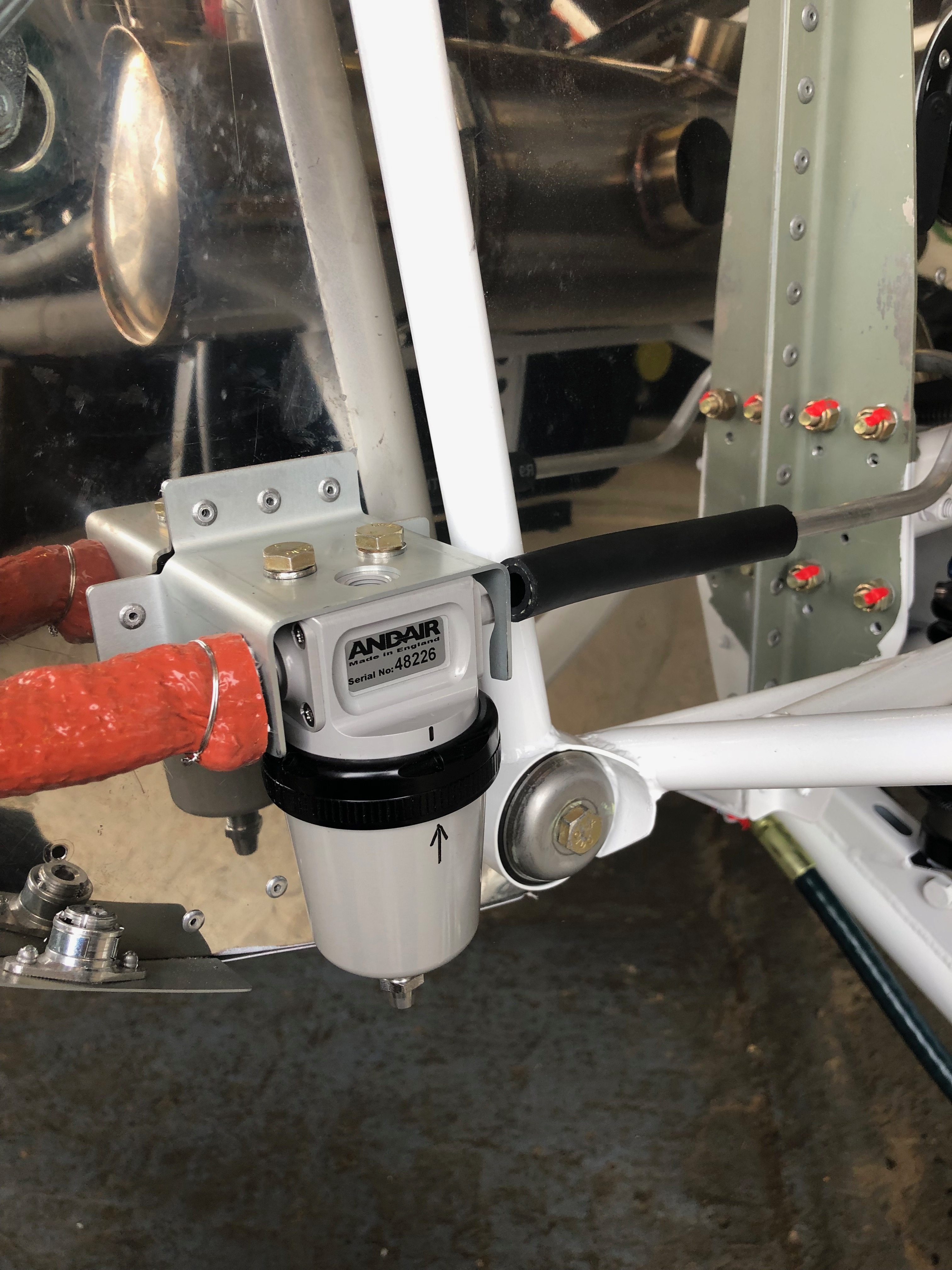
The exhaust seems to clear the cowl however another check will be made before final assembly. The gascolator is located on the opposite side to the exhaust pipe and requires a hole to be drilled which will enable fuel checks to be carried out before flight.
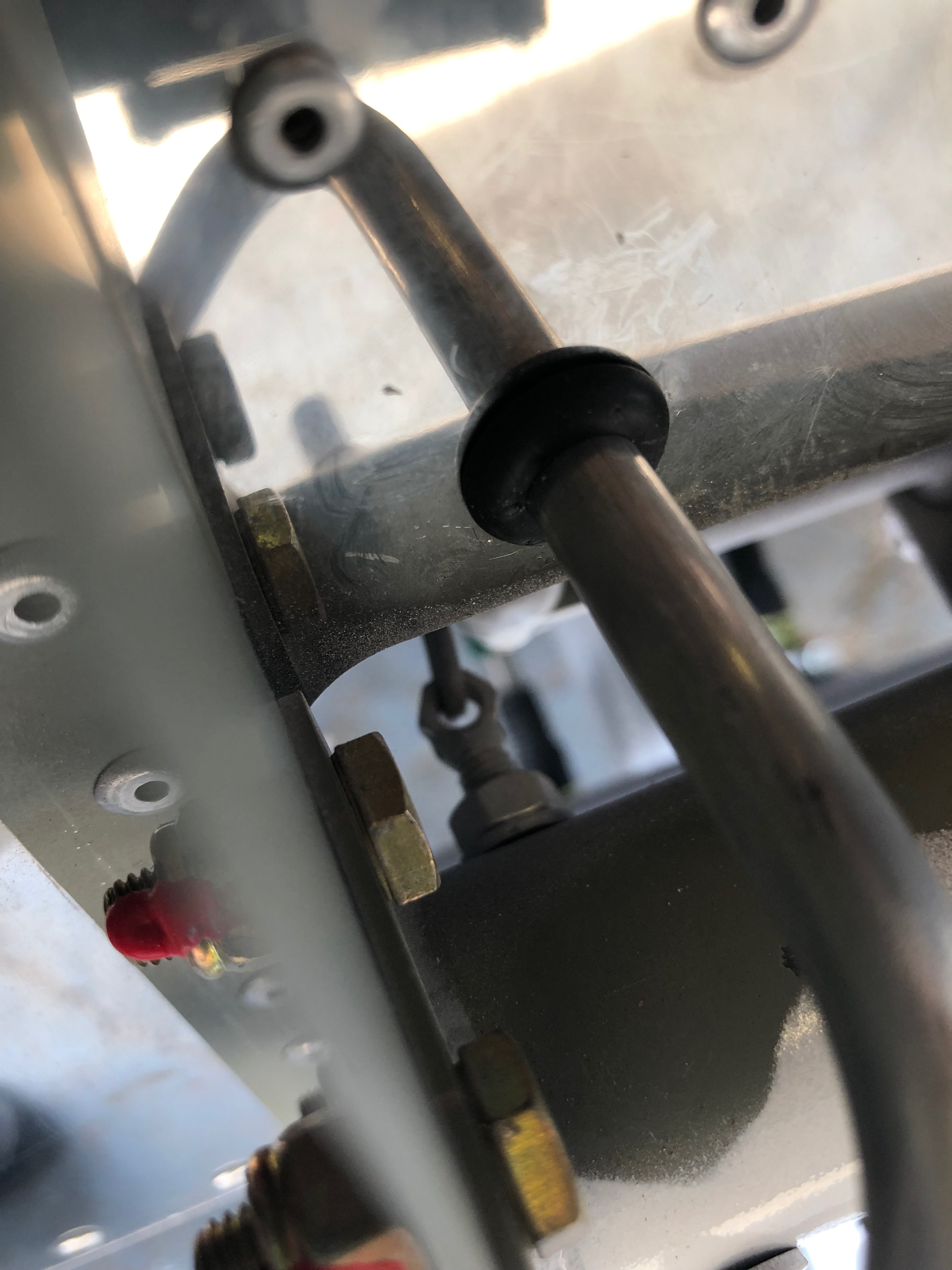
The installed thermostat with just a ‘stand off’ to be fitted to make sure it doesn’t rub against the adjacent engine mount.
Now the cowl fitting has proven All the clips are fitted – job done.
I purchased a Kavlico EMS kit so the EGT sensors need to be installed.
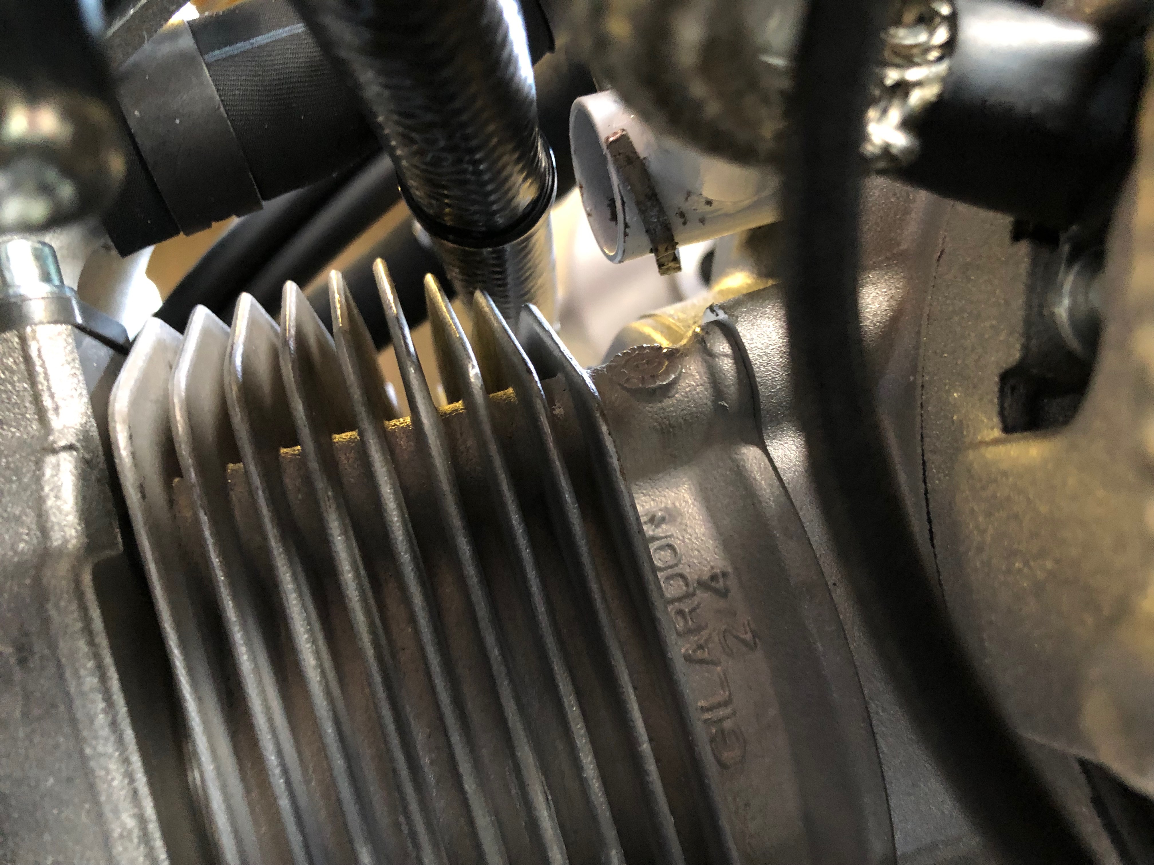
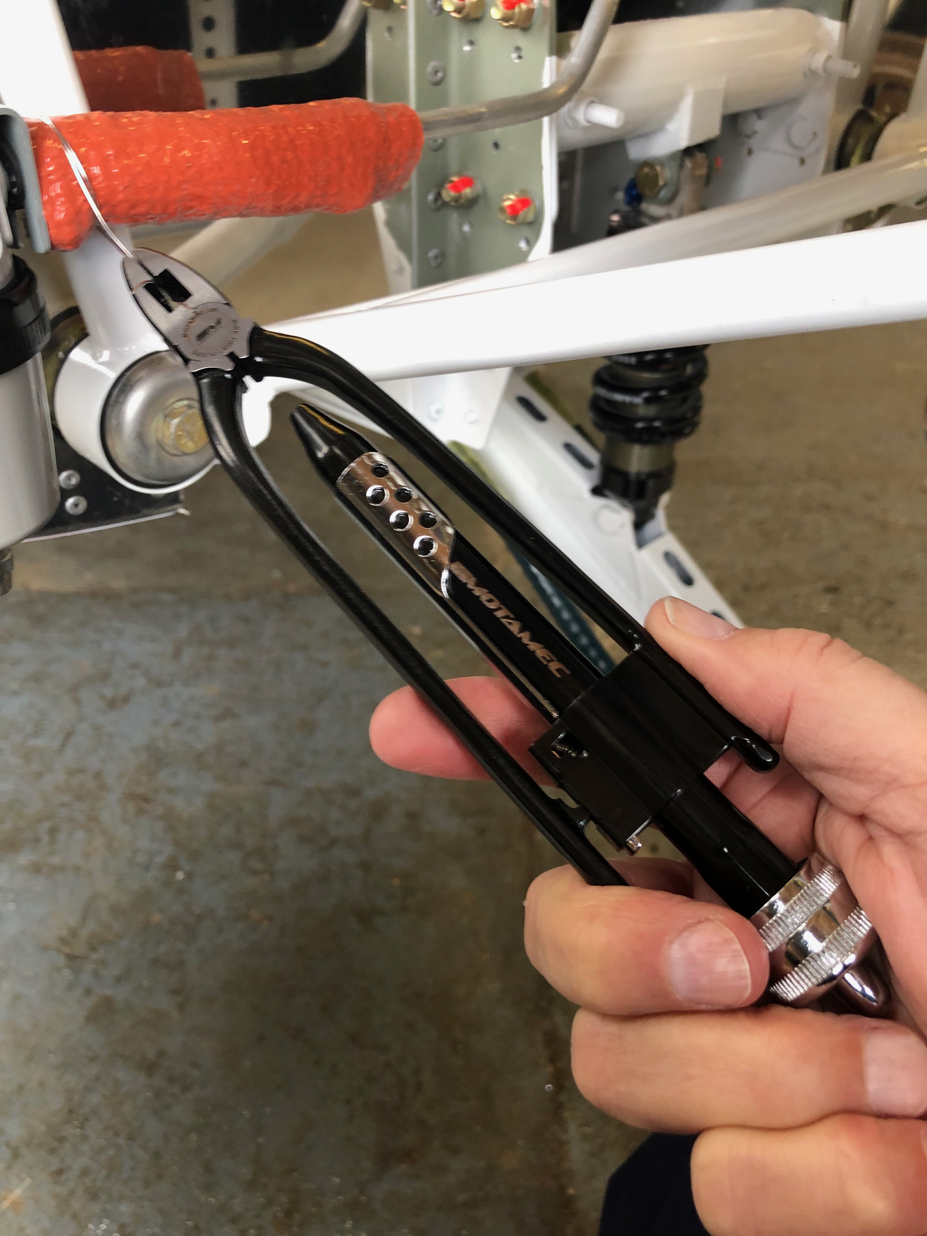
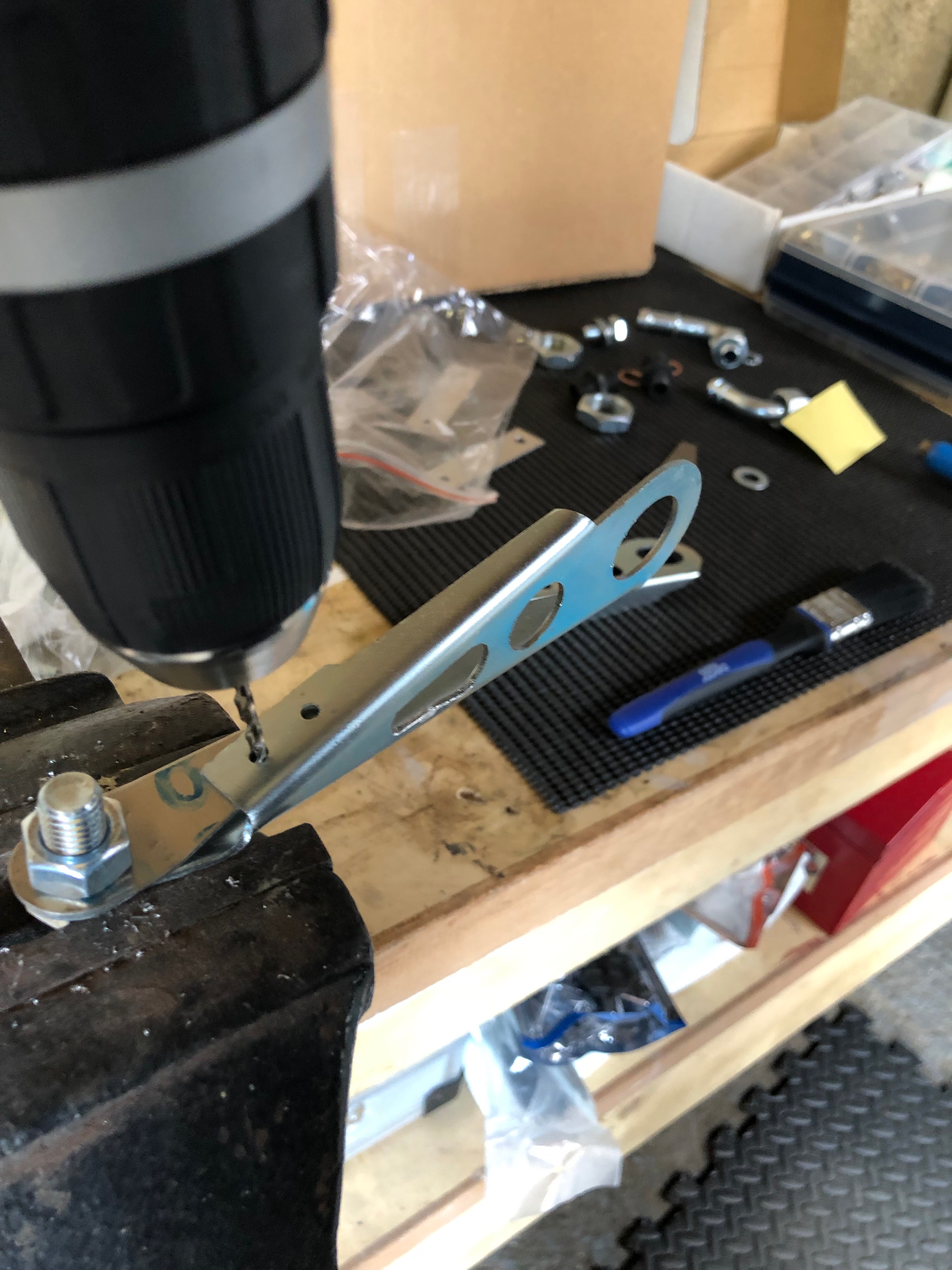
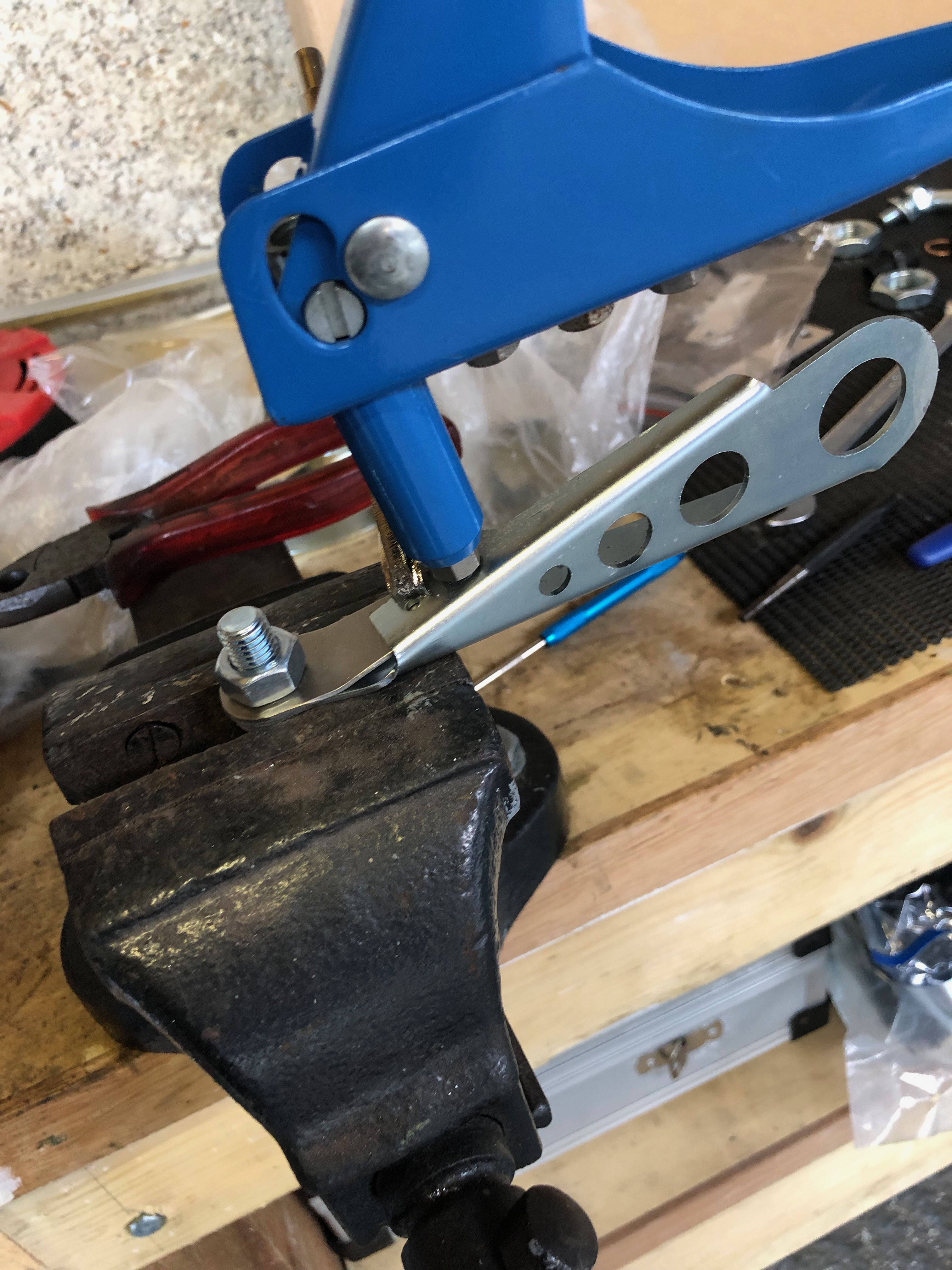
A 3.2mm hole needs to be drilled in the rear exhaust downpipes 4″ from the flange.
Once the hole is drilled and sensor fitted it is held in place with the supplied, modified jubilee clip. The sensor has a ‘collar’ that ensures that the hole is sealed.
The downpipes are re-fitted and re-wrapped, securing in place with stainless steel ties.
To ensure the springs don’t fall and cause a runway hazard if they fail in service they are wire locked. Tomorrow I will fill the centres of the springs with heat resistant silicone which reduces any resonance from the springs.
Today was set out to redo some piping that I wasn’t happy with, re site the water radiator support bracket that seemed to be straining then continue the fuel system and oil system install.
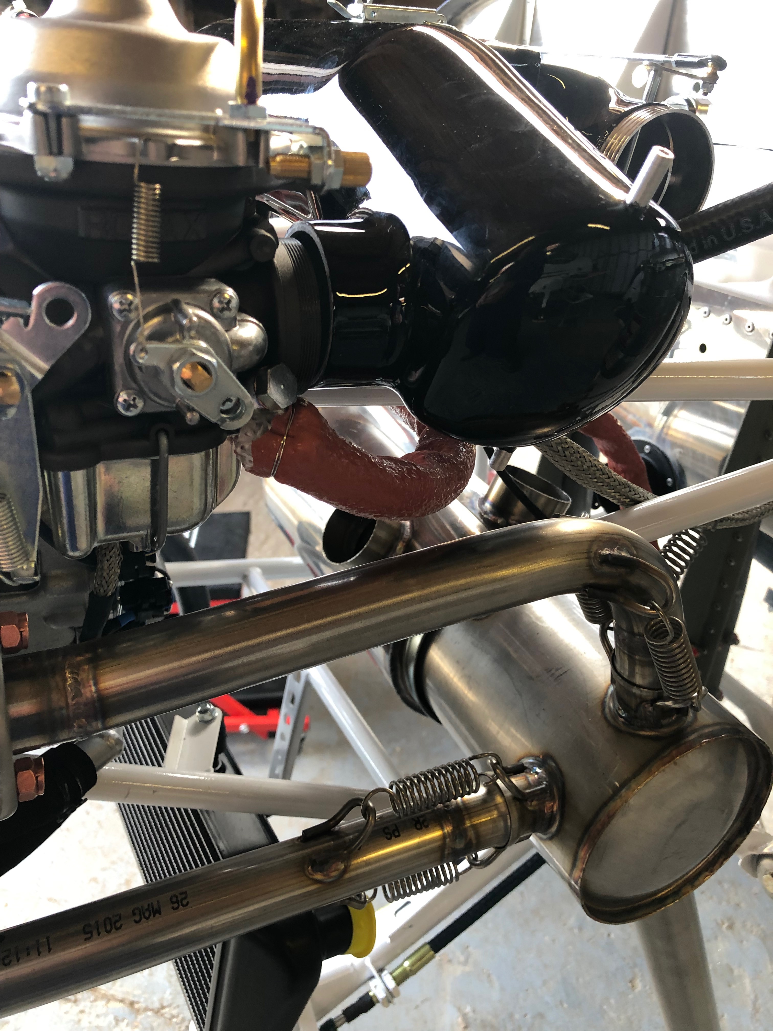
I wasn’t happy with this pipework so I changed the angle of the carburettor banjo and shortened the fuel pipe.
The change resulted in a much neater installation.
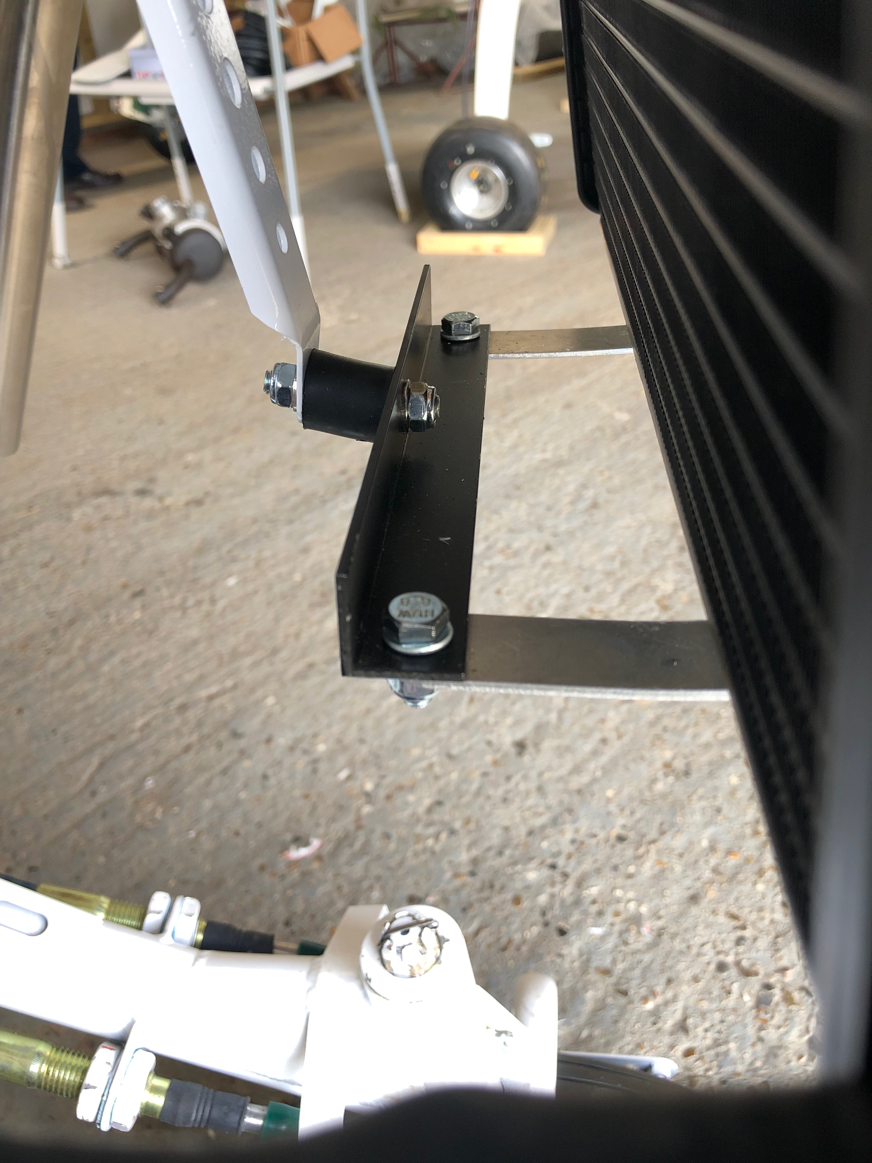
The aluminium water radiator brackets were moved to underneath the black bracket which seems to work much better than the original fit.
The oil system is next. Most of the time taken to install the piping is working out the the route to make sure that it doesn’t rest or rub on other parts of the engine and it has a natural route which doesn’t lead to kinking of the pipe.
The oil supply hose is fairly easy to route but still requires careful positioning and ‘stand-offs’ to make sure nothing rubs.
There’s not a lot of space as you can see here.
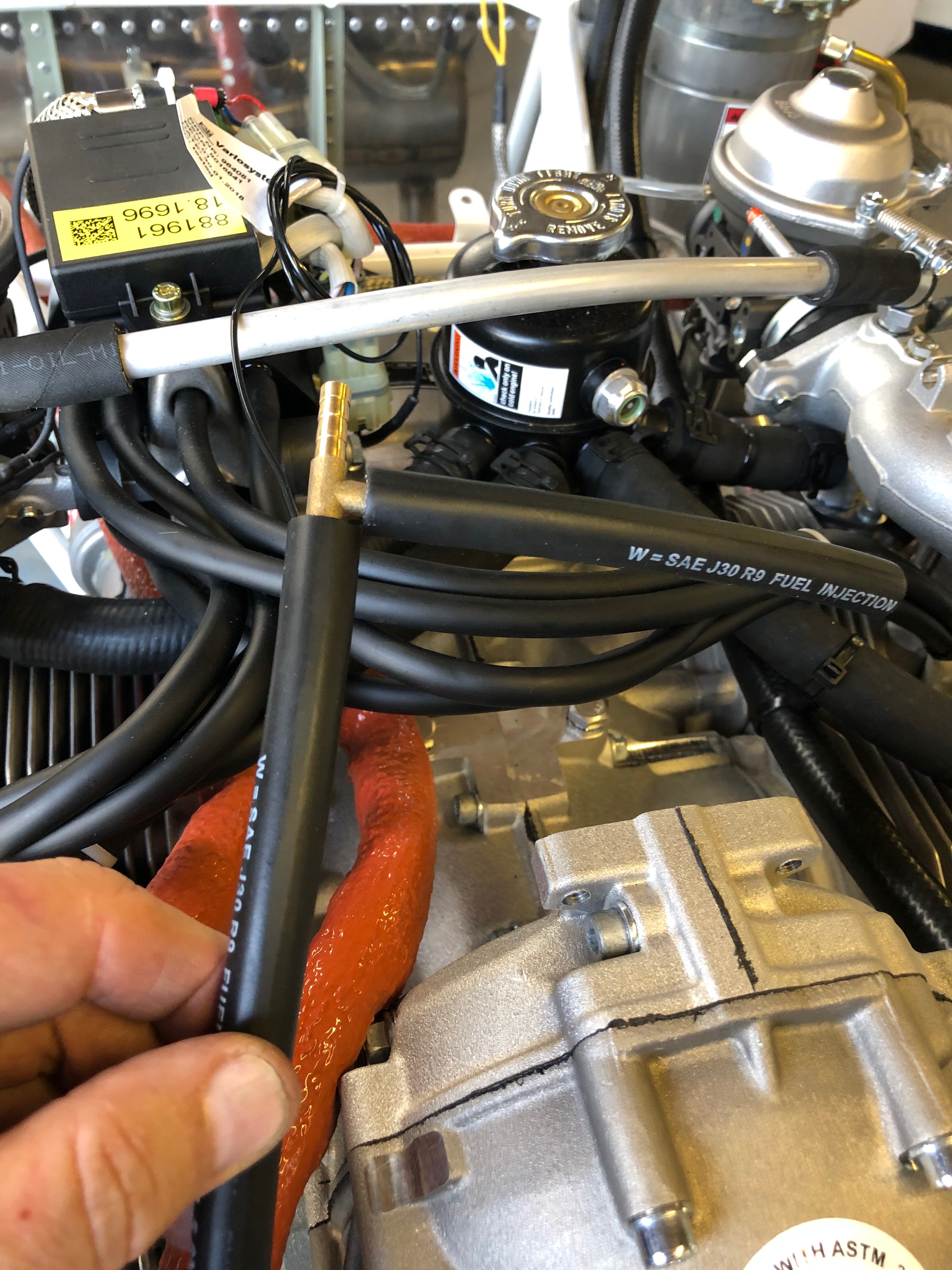
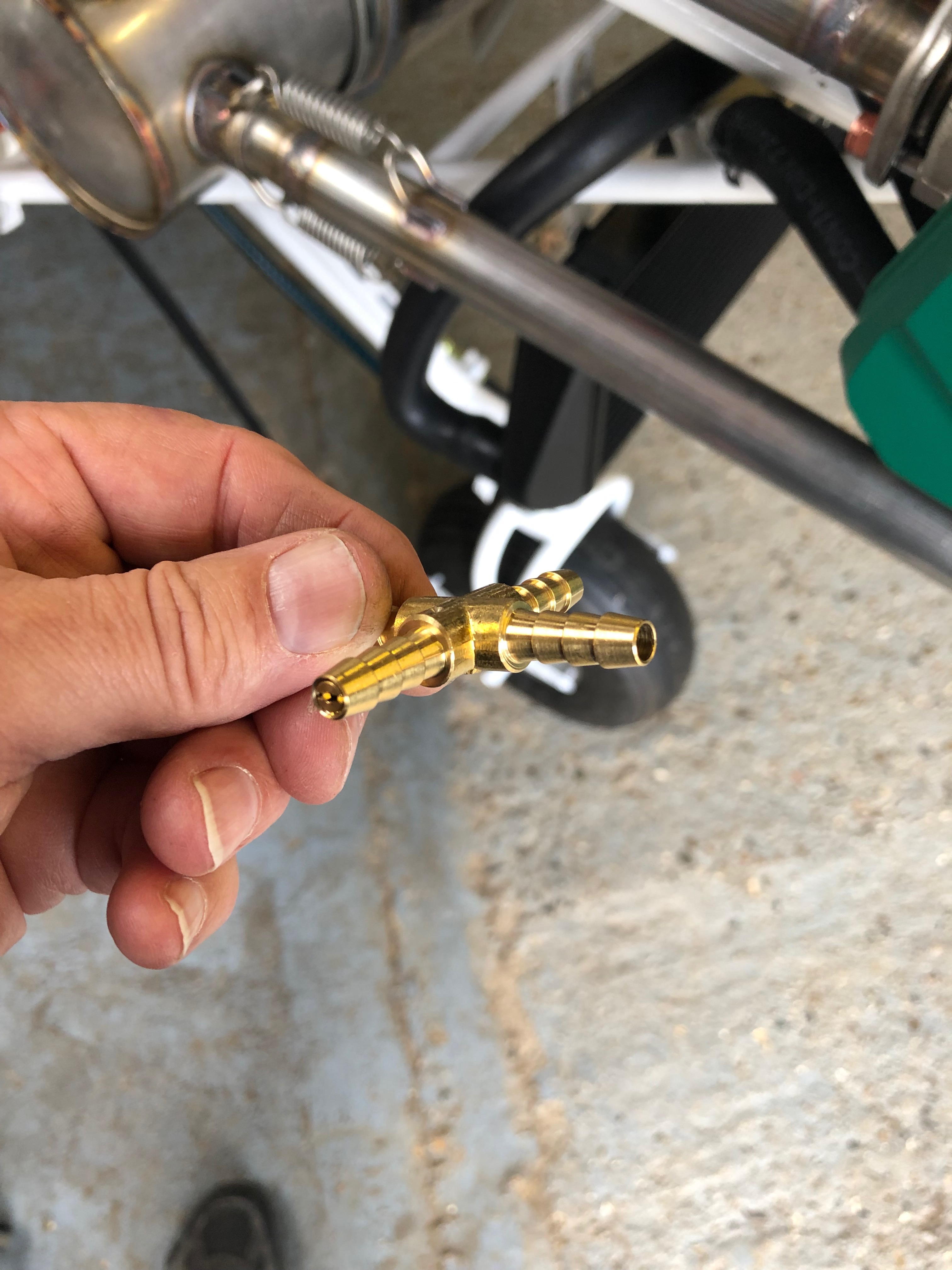
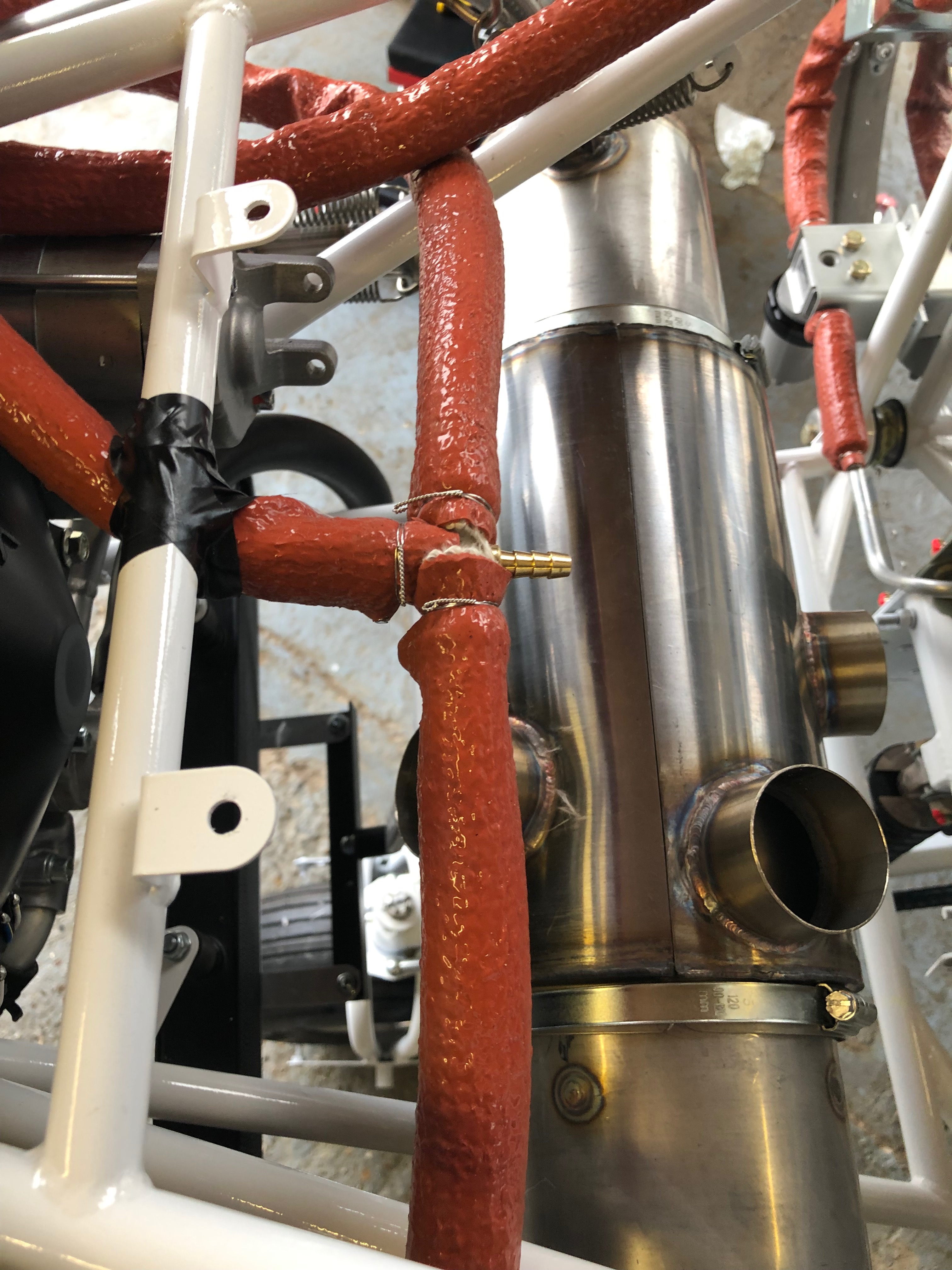
Last job for today is to make the tee for the fuel pressure sensor. This will be fitted in the fuel line between the mechanical fuel pump and the cross connector that has the restrictor installed. This will ensure that the sensor reads the correct pressure.
The Tee must also have fire sleeving and secured in place with wire wrap.
First thing to do today was to fit a grommet in the firewall for the aluminium fuel pipe to go through and be supported and stop it chaffing.
The final screws arrived so I can now completed the installation of the water radiator.
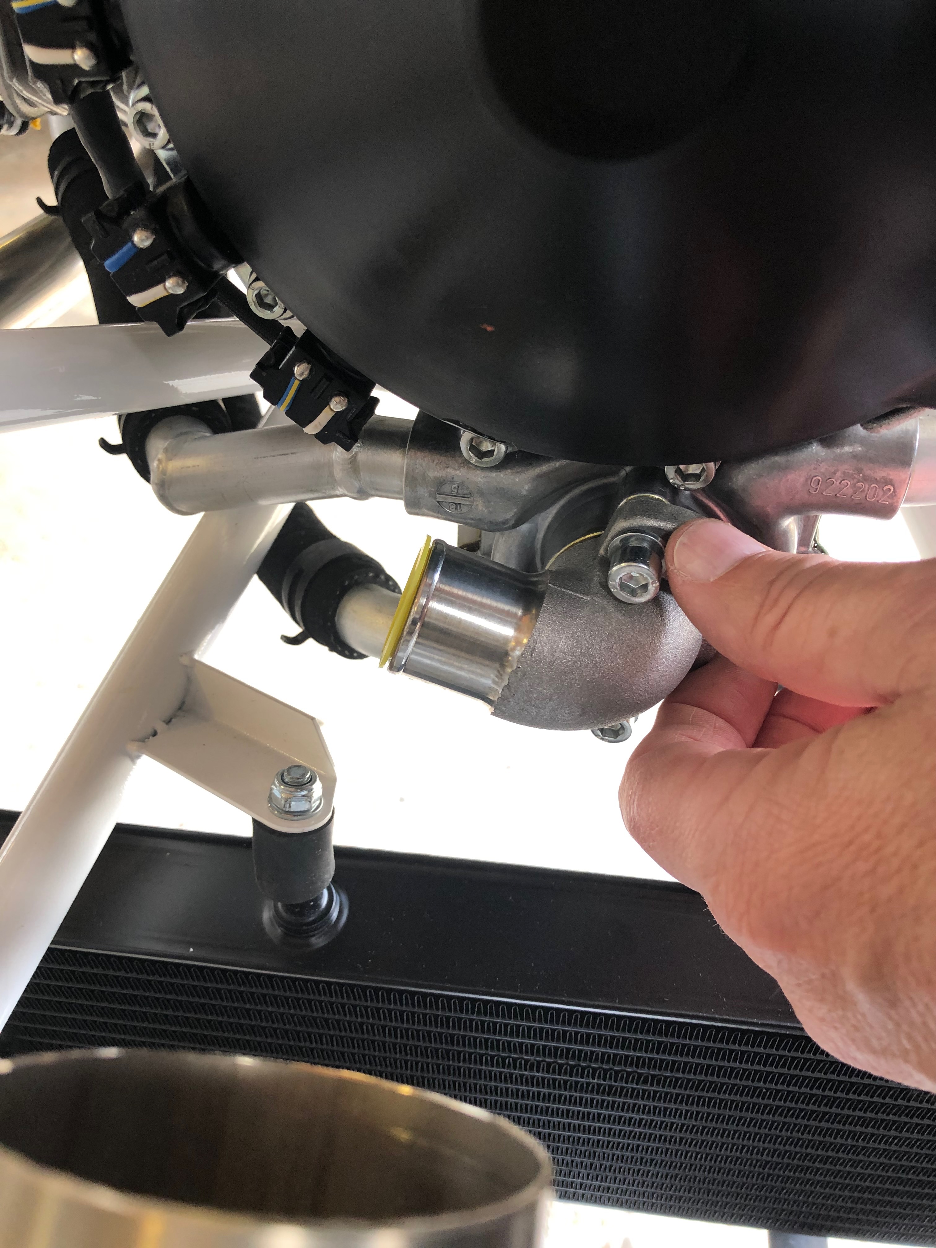
The water pump outlet needs to be repositioned to allow it to be piped to the radiator.
Trial fitting of the pipe to make sure the pipe run doesn’t snag any other pipes or brackets.
Re-fitted the water pump outlet and tightened the screws with Loctite 643
Now the grommet has been fitted I can complete the installation of the fuel feed piping to the gascolator.
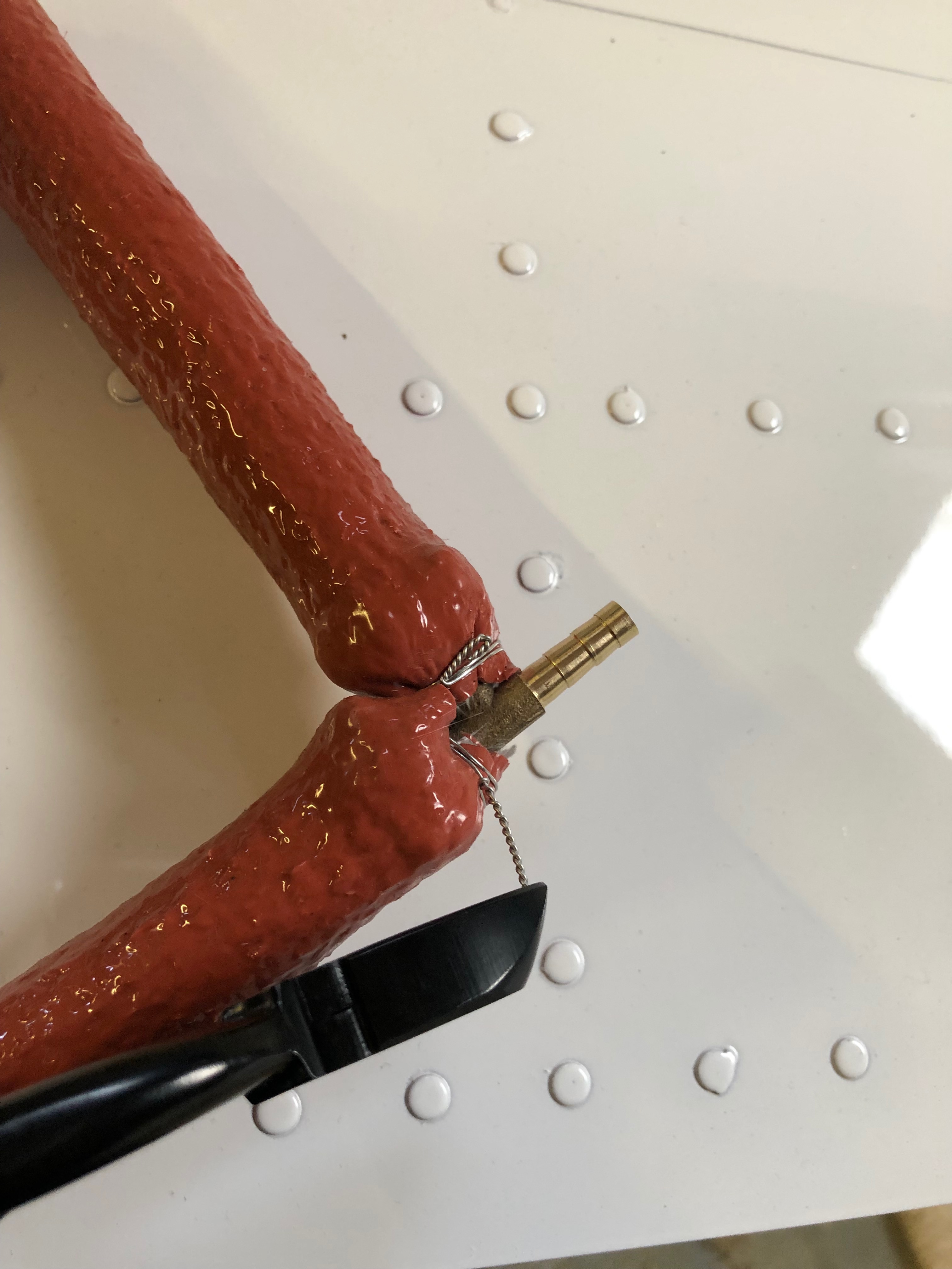
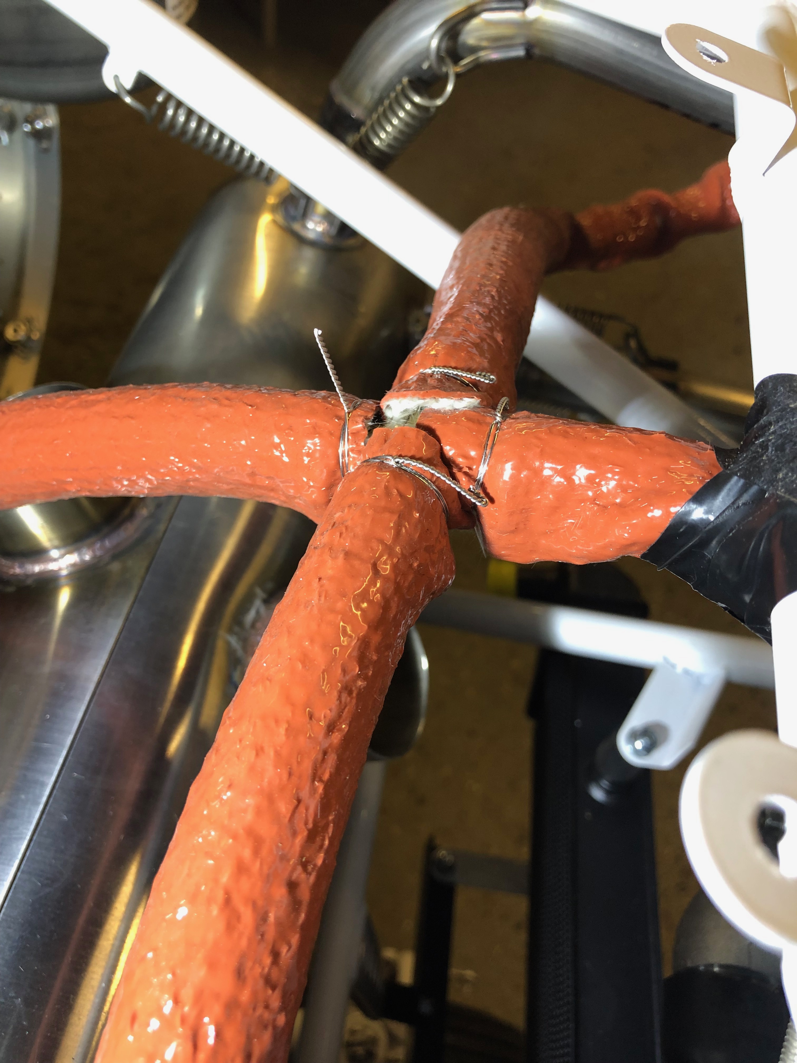
All the pipes are clamped with a hose clamp and fire sleeving is slid over the whole assembly and secured with aircraft grade stainless steel wire wrap. This ensure the fire sleeving doesn’t move and ensures the fuel pipes are protected in the event of an engine fire.
An example of a completed wire wrap.
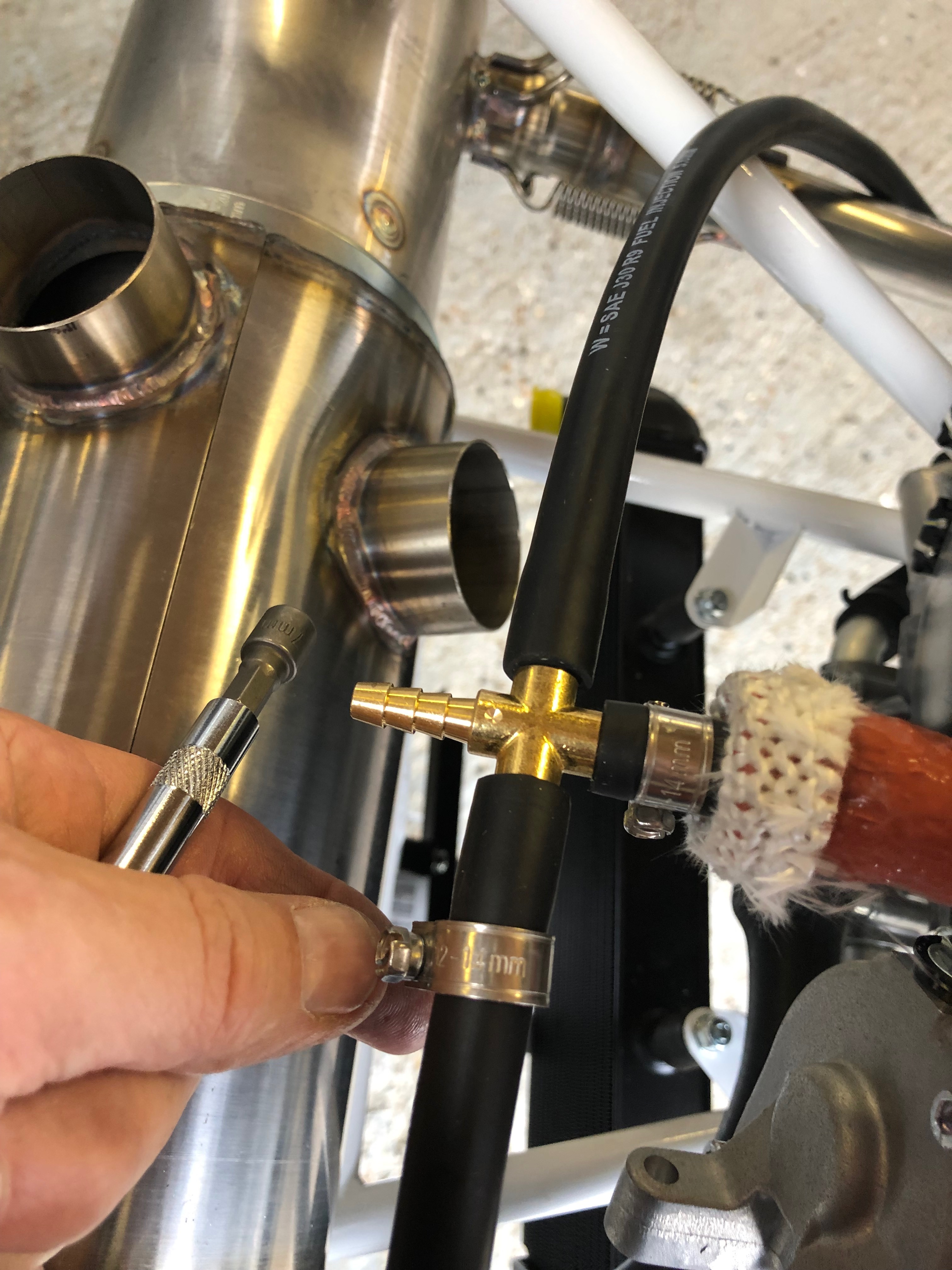
The flow from the mechanical pump supplies the carburettors and then a return is taken to the lefthand fuel tank this allows a constant feed of fuel to circulate the fuel system and alleviates the chance of a vapour lock. The return feed is restricted by an insert in one branch of the cross connector (see photo) this ensures the carburettors get sufficient supply of fuel.
The cross connector centrally installed with the return line connection still to be completed.
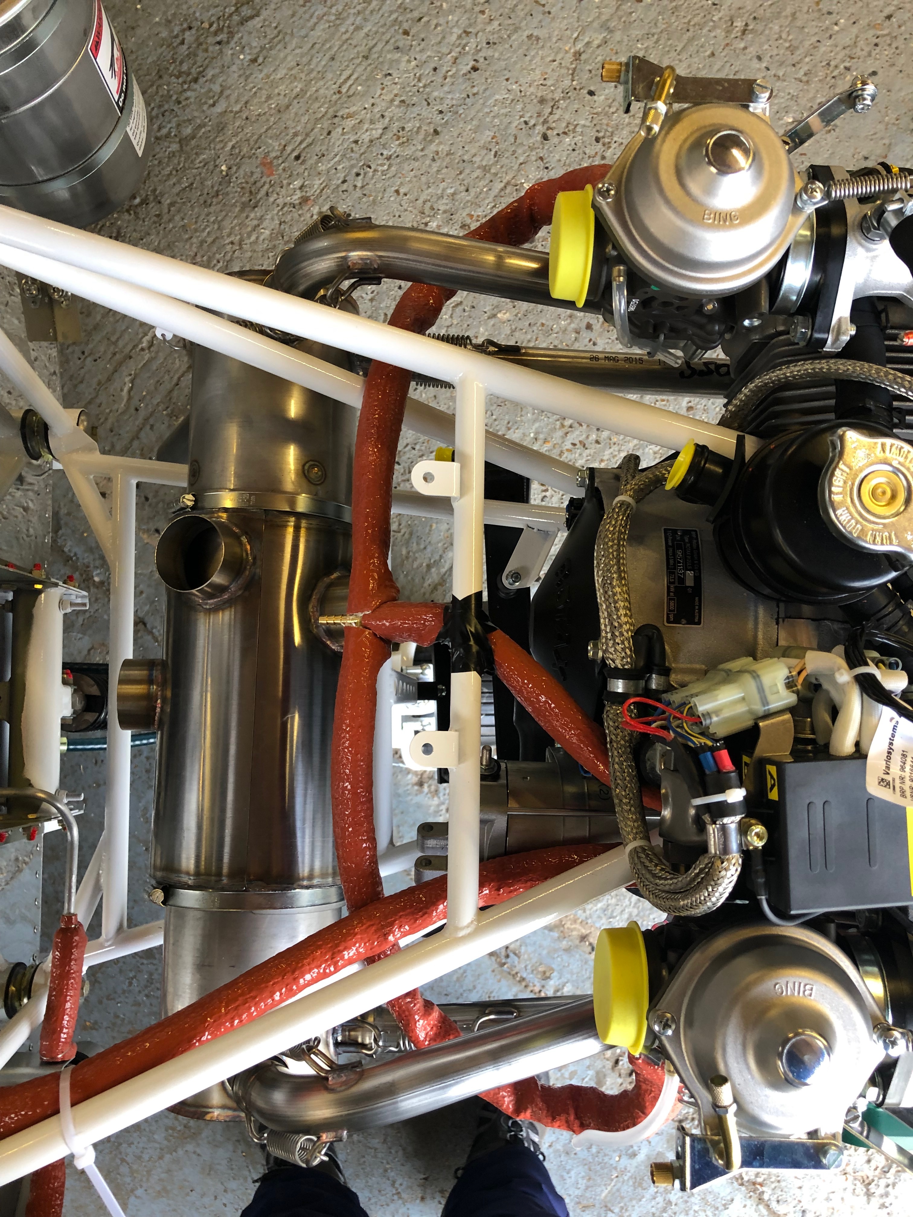
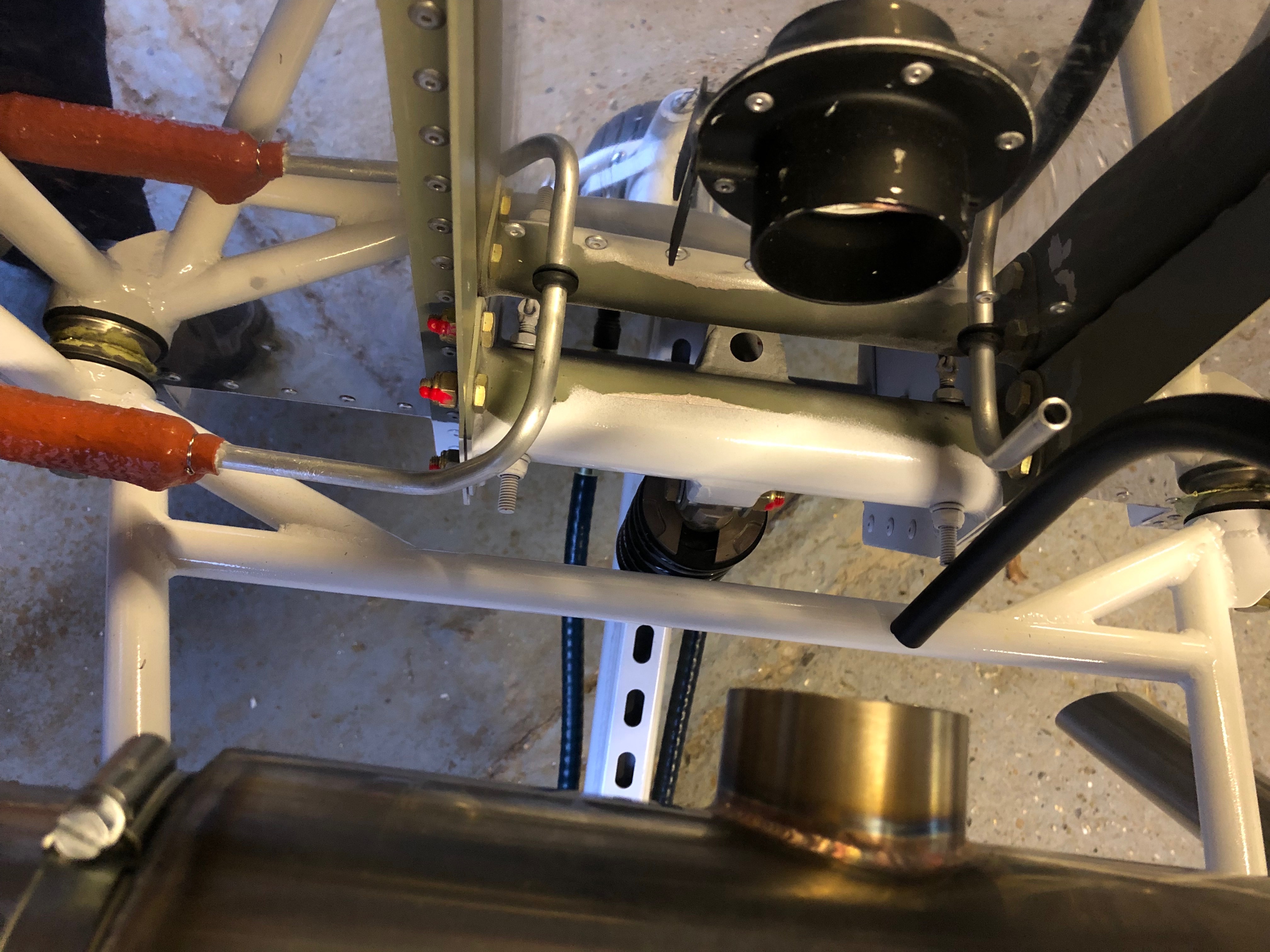
An view from overhead showing the positions of the pipework to date.
view form the left hand side Before the return line is installed the aluminium return pipe needs to be fitted.
It’s a tight squeeze in the nose wheel tunnel but with perseverance the connection is made and the hose clips tightened. This piece of tubing doesn’t need the fire sleeving because it is behind the firewall.
Return pipe installed.
Once a wire wrap has been carried out the end is cut off as leaves a very, very sharp barb. To ensure that it doesn’t cut into you when carrying out maintenance the end it bent over on itself and pushed down .
The return line now completed.
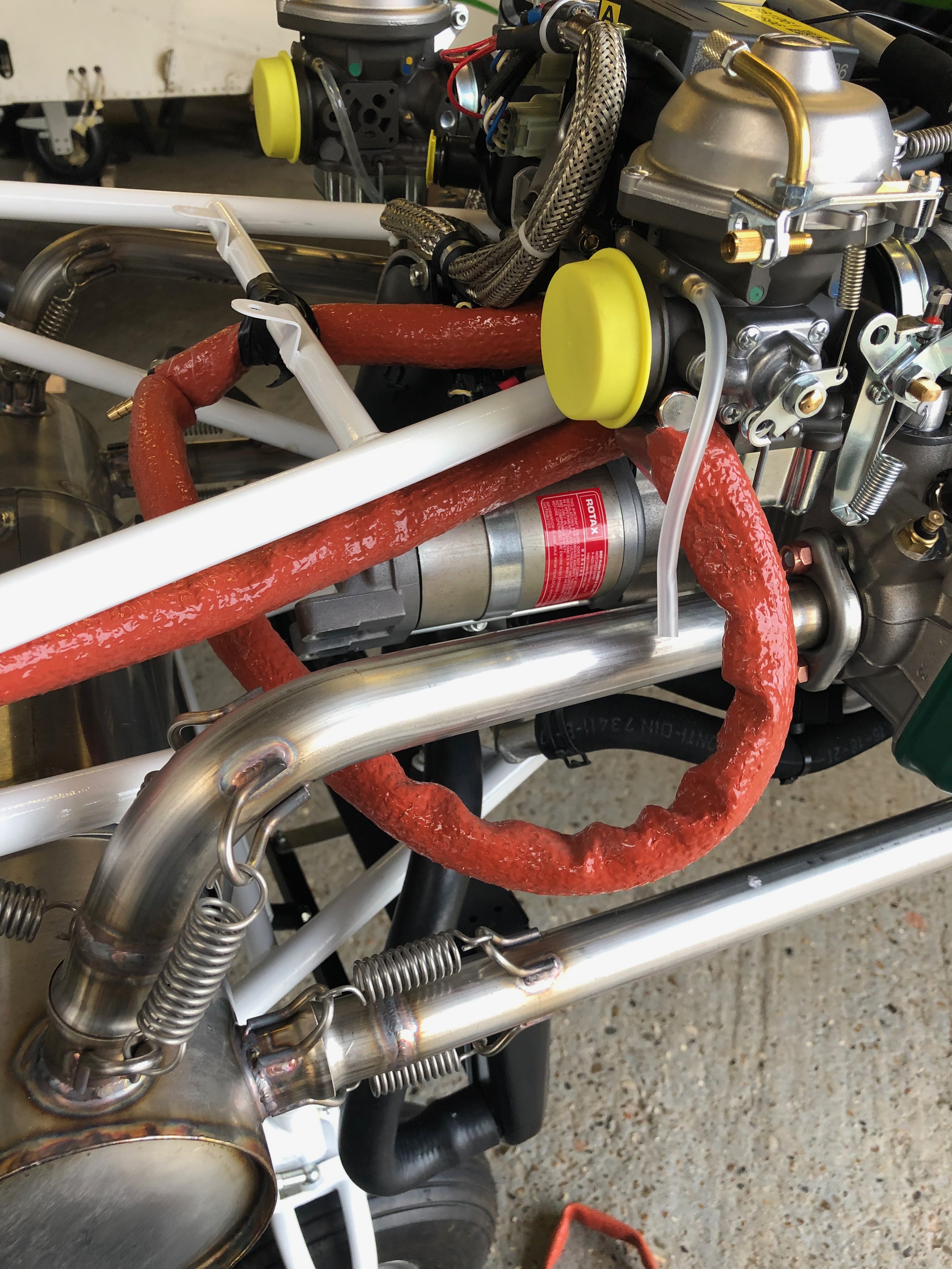
I completed the piping to the carburettors but having reviewed the run I’ve realised that it’s not the best installation. I will re run the pipes tomorrow so they are a lot shorter and won’t run round the exhaust like they are in this photo.
The missing parts arrived in the post today so I was able to get on with some of the tasks that have been stalled.
First job today is to add strengthening to the oil coolers bracket. The strip of metal is bolted to the bracket and holes are drilled to accept 2 rivets.
Rivets are installed.
The finished brackets ready for install.
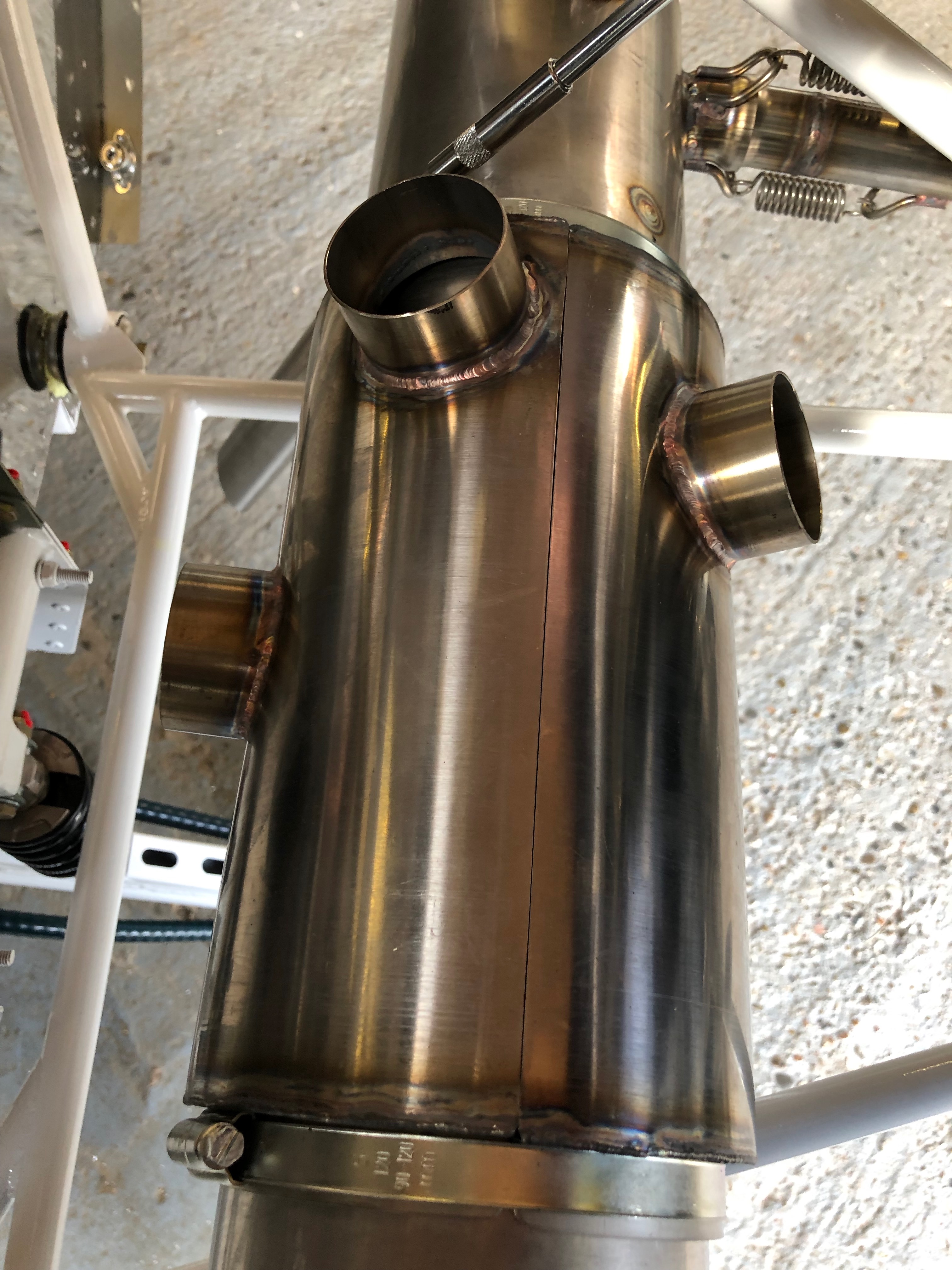
Next is to clamp the heat exchanger, for cabin and carb heat, onto the exhaust with large jubilee clips. They are no tightened at this point as it may need to be rotated later.
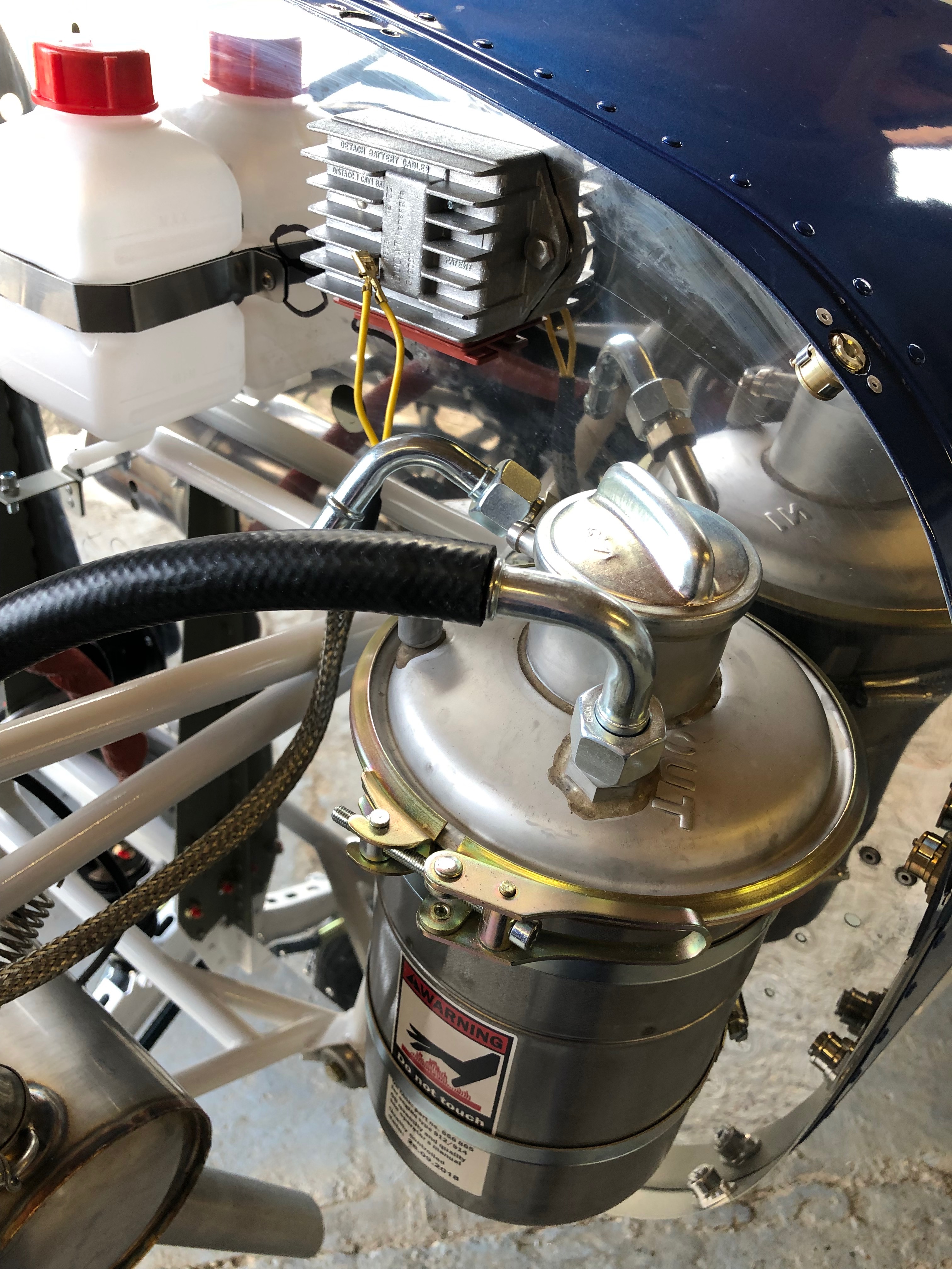
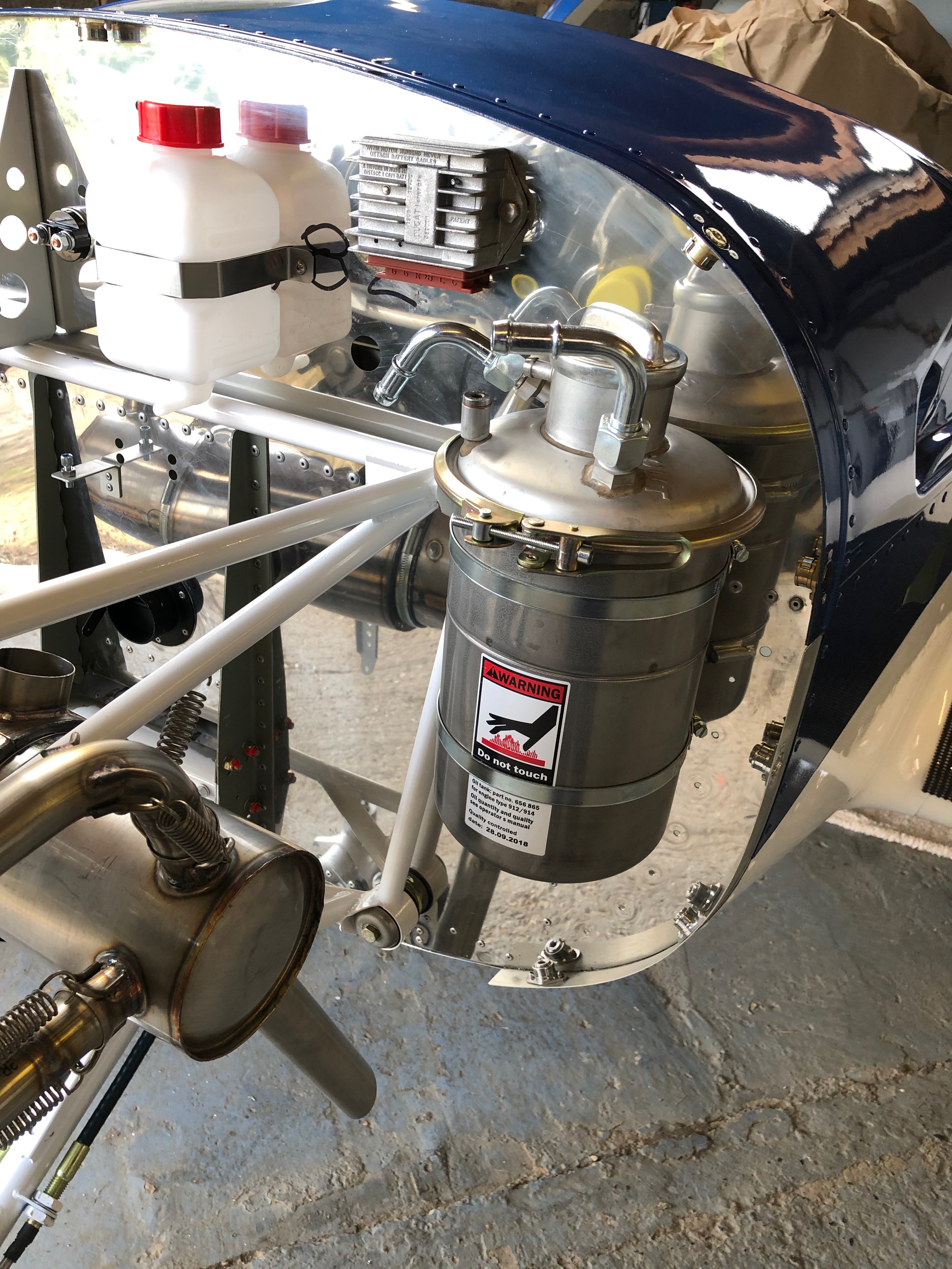
The oil tank is secured with large jubilee clips. Thinking about the location of the screw clamps I decided to turn them round.
Tank now install and the screw clamps are now ‘hidden’ at the rear of the tank. I’ve also turned the tank clamp around which makes it easier to undo for servicing.
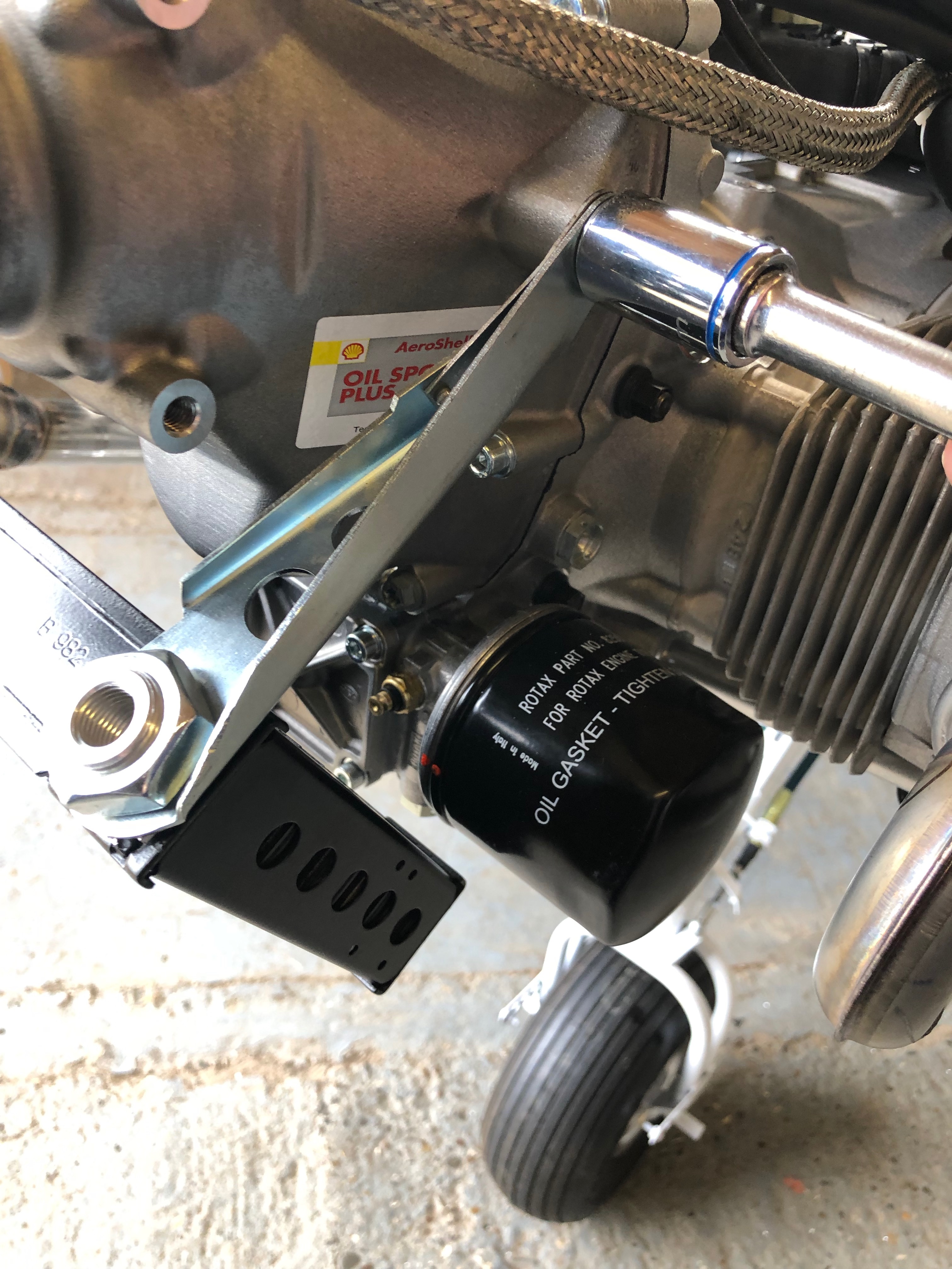
Now the oil cooler brackets have been strengthened it’s time to install the oil cooler.
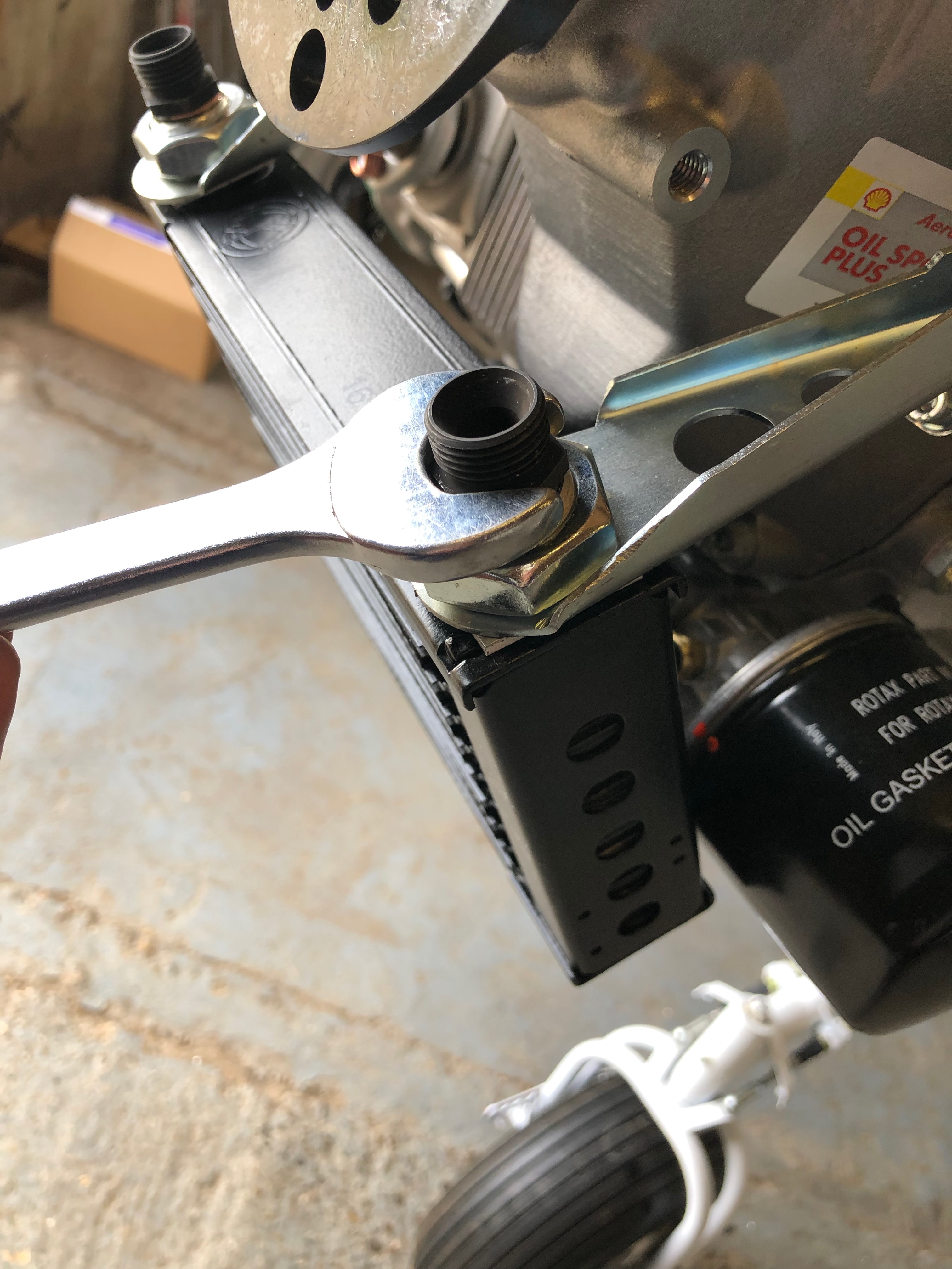
A reducer is installed to for the oil hose connectors.
Oil pipe connectors installed.
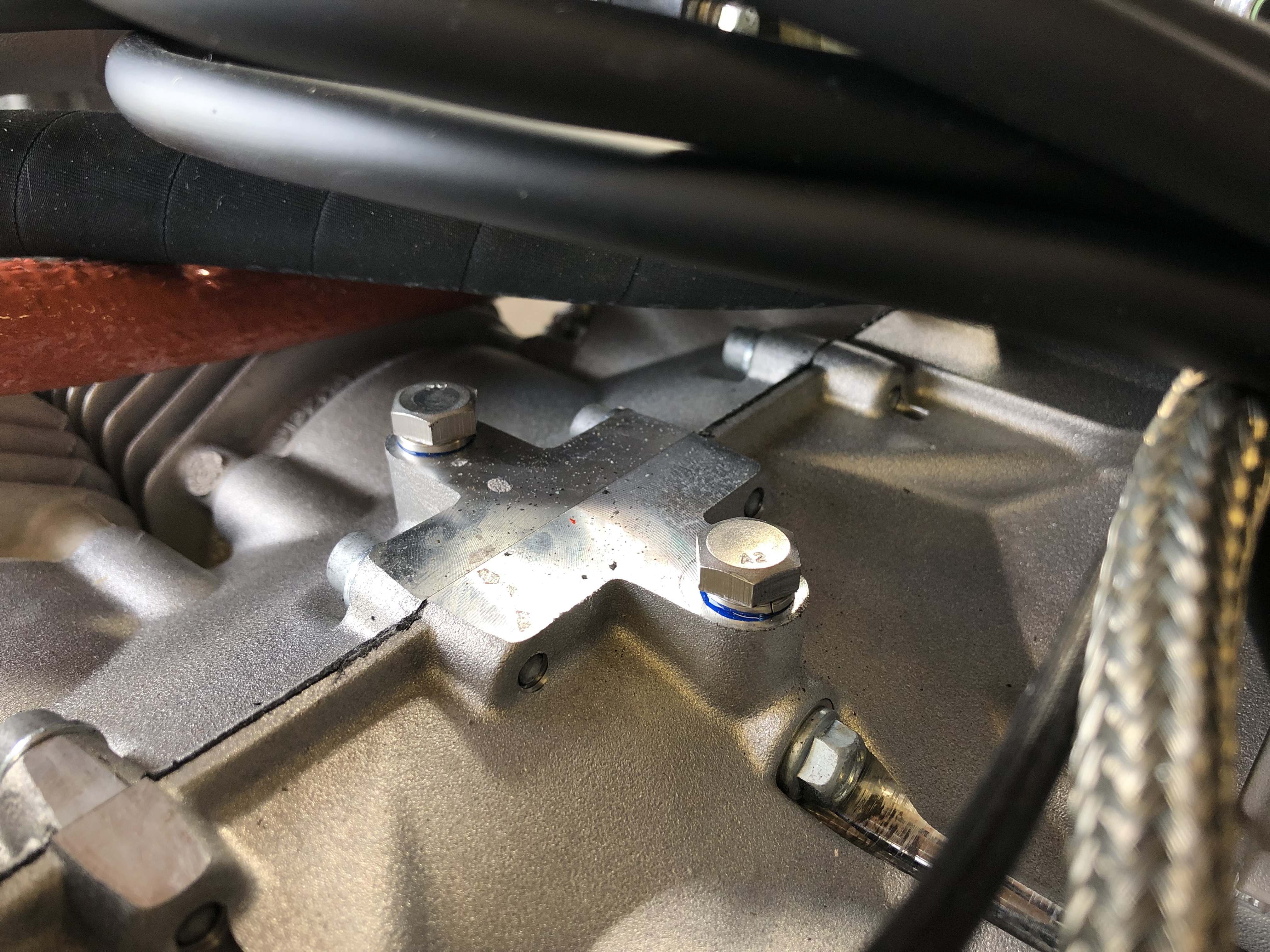
2 bolts are installed and locked with Loctite 243 to stop dirt and muck filling the lifting bracket mounts.
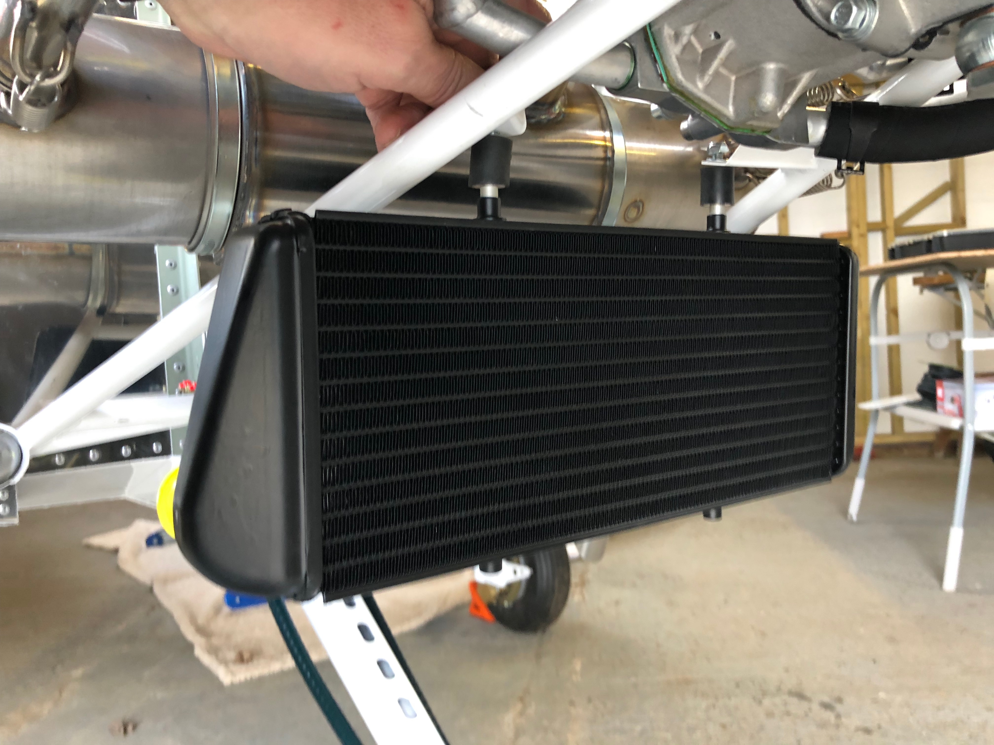
The water cooler is installed next and requires a couple of brackets and 5mm spacers to be made.
I think that’s close enough…
The 2 spacers are fitted on the rubber vibration isolators, screwed into the top of the water radiator and secured with 2 M6 nyloc nuts.
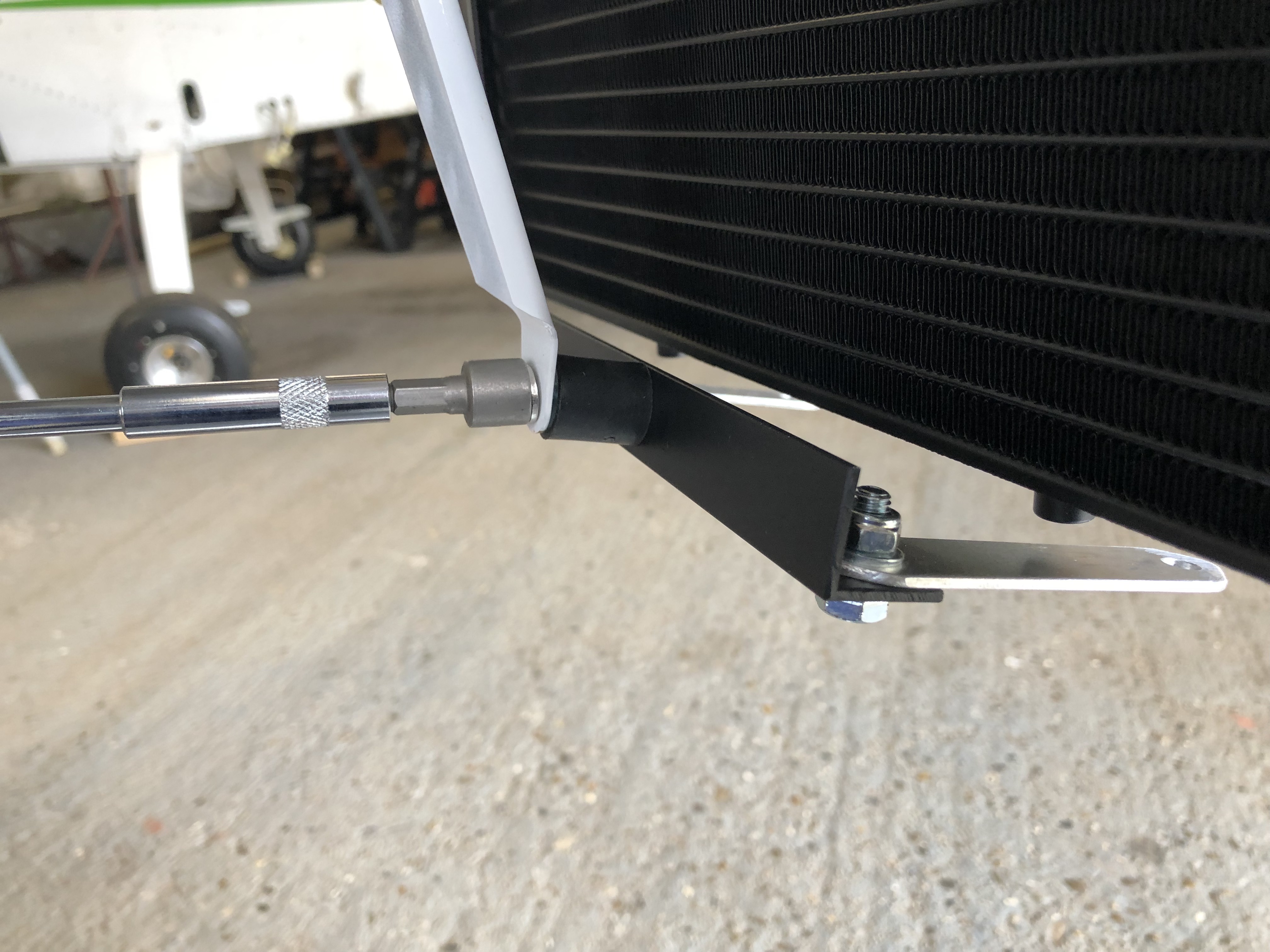
The aluminium brackets are fitted to the lower support…
and secured under the water radiator. I need to finish the final securing tomorrow.
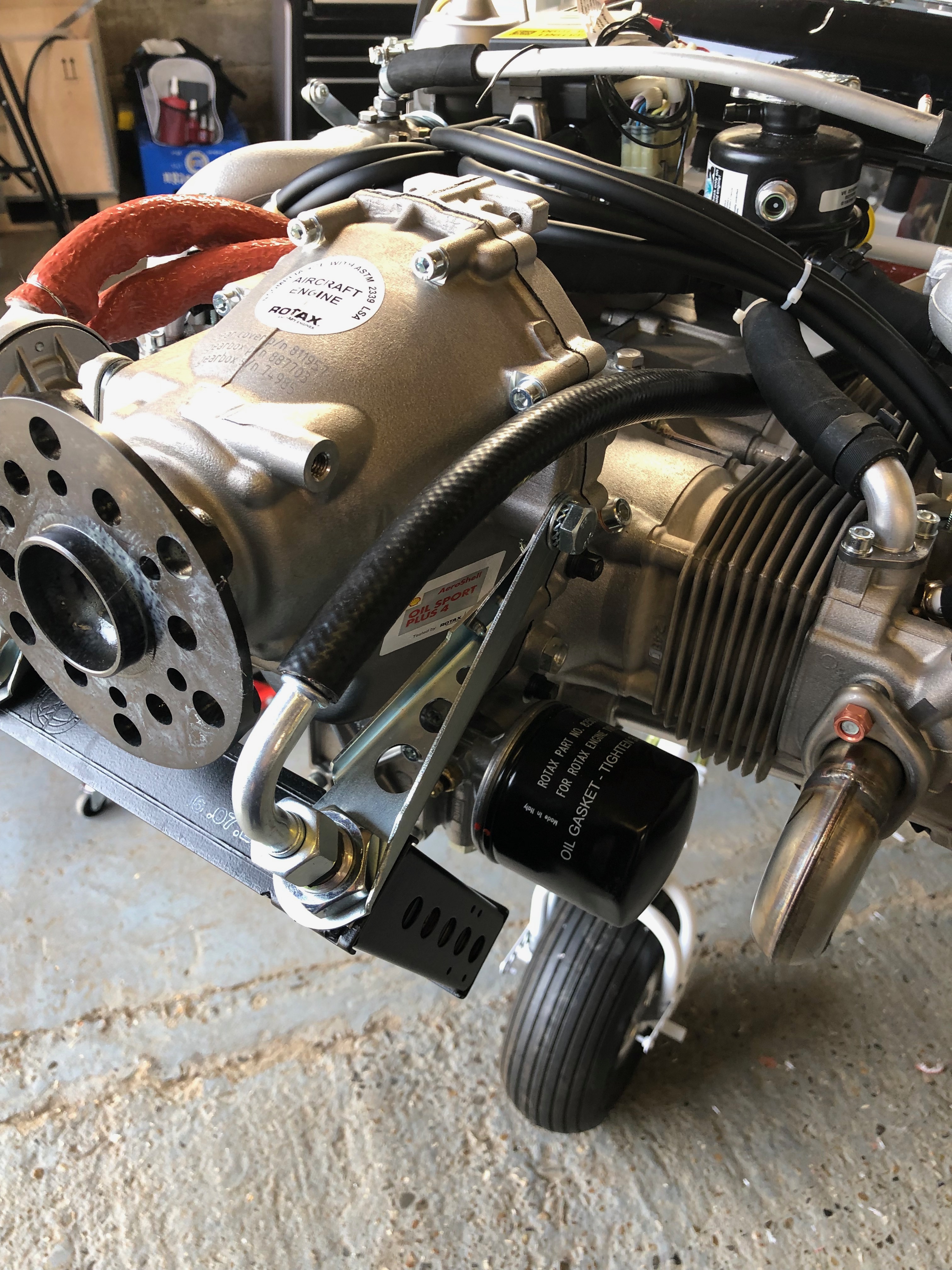
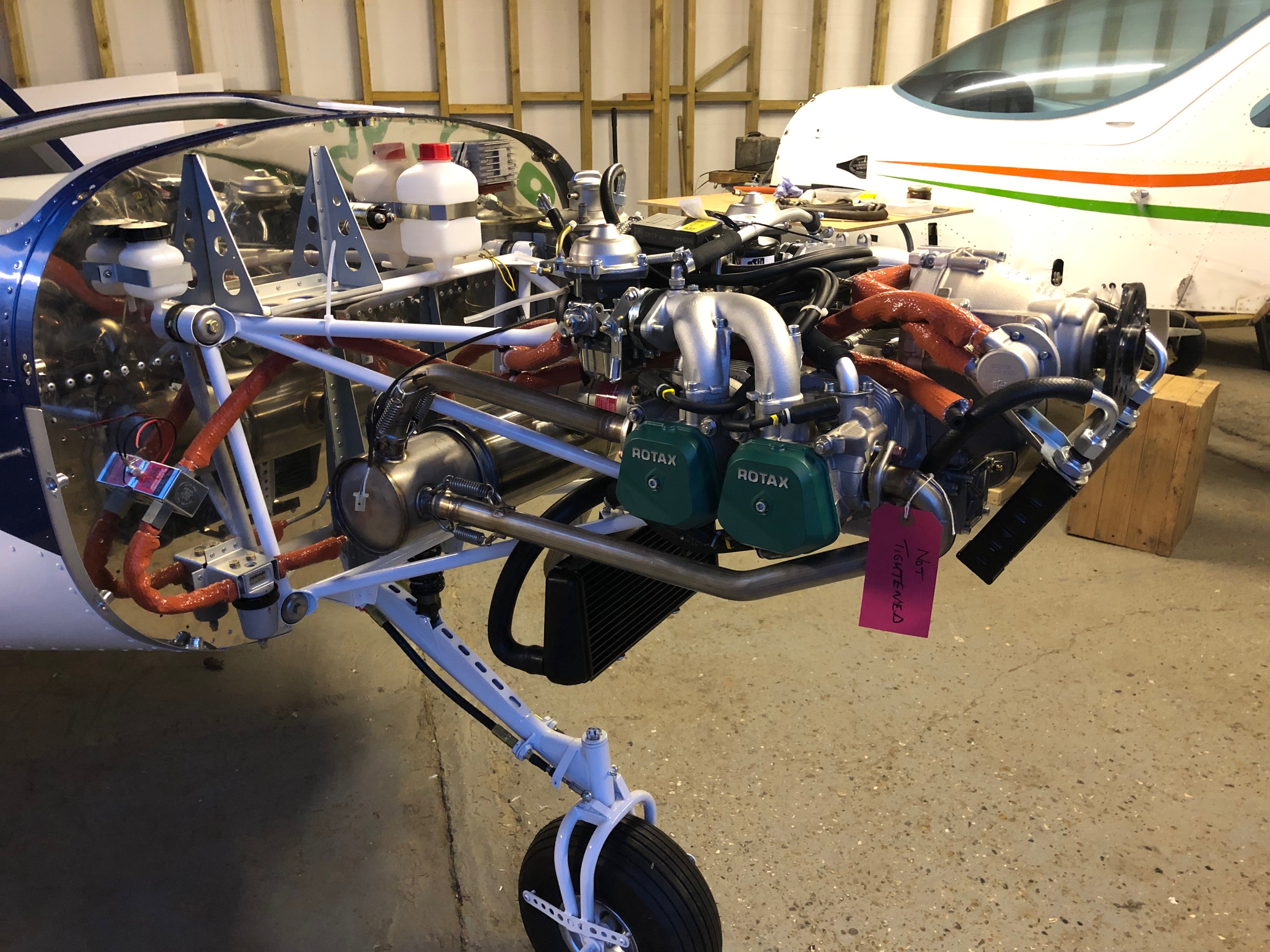
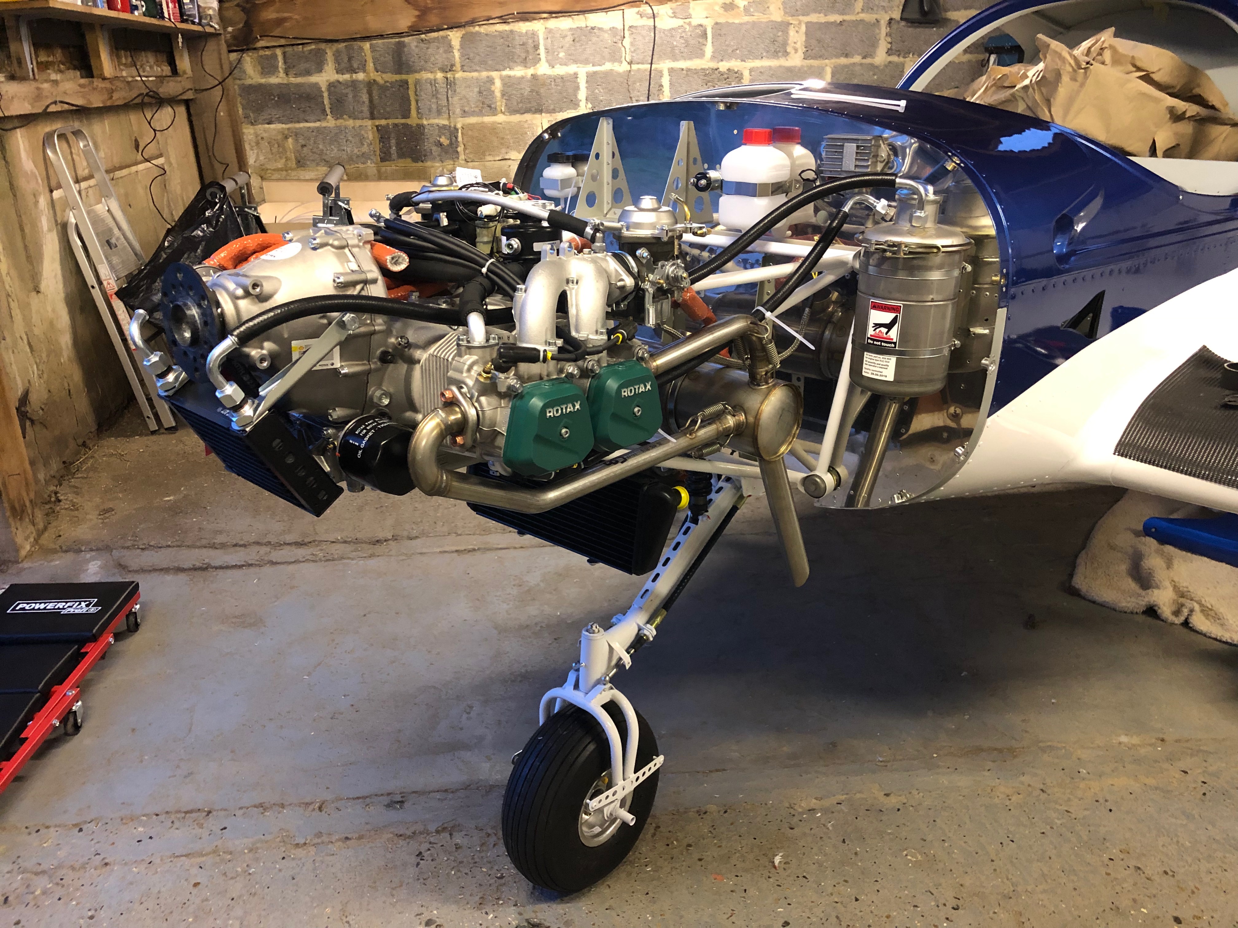
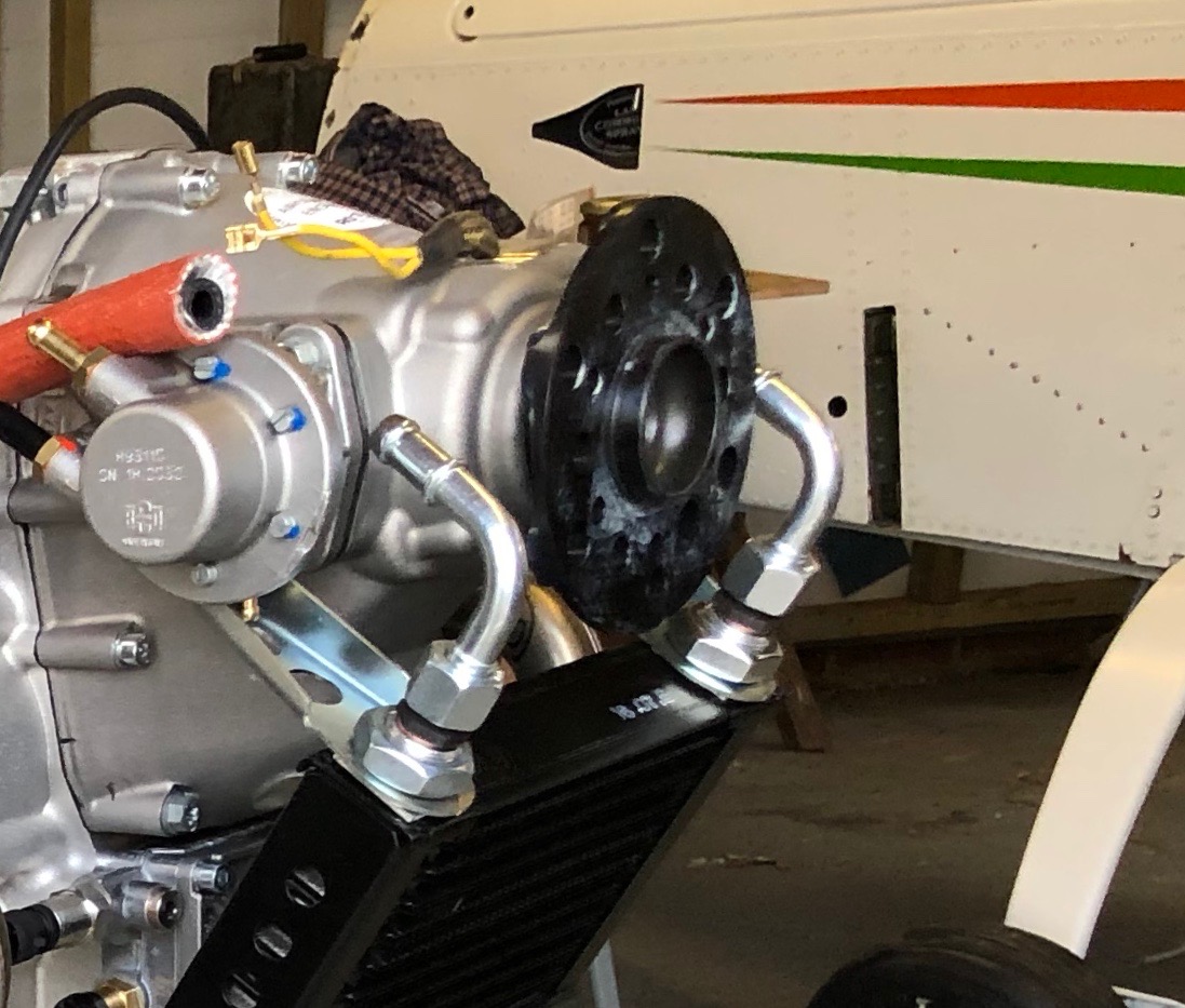
Engine installation so far – Right.
and from the left.
Following the build of my Bristell NG5 Kit No. 382 Registration G-MLSY