Yesterday we received an instruction from Bristell UK to remove the coolant thermostat if you had fitted one. They state that two Rotax 912 ULS engines have had to have cylinder no. 1 replaced due to overheating and they claim that the thermostat caused. With no other information it seemed sensible to remove it although now I effectively have a €250 aluminium 90 degree connector. Quite frustrating.
The Silent Hectik thermostat. Very well made with a 80 deg C thermostat hosed within it.To remove the stat required the casing to be heated with a hot air gun. That softened the Loctite holding the screws. Once removed a little bit of Wellseal is used to help seal the ‘O’ ring, Loctite applied to the screws and then reassembled. As I was going to use the housing as an expensive 90 degree connector I thought it was a good idea to mark the casing with “Thermostat Removed’. Reinstalled and ready for the system to be refilled with coolant. Job done in just over an hour.
Music: Karen was in charge of music so played tracks like ‘I can fix you’ and ‘All right now’ Very funny Karen!
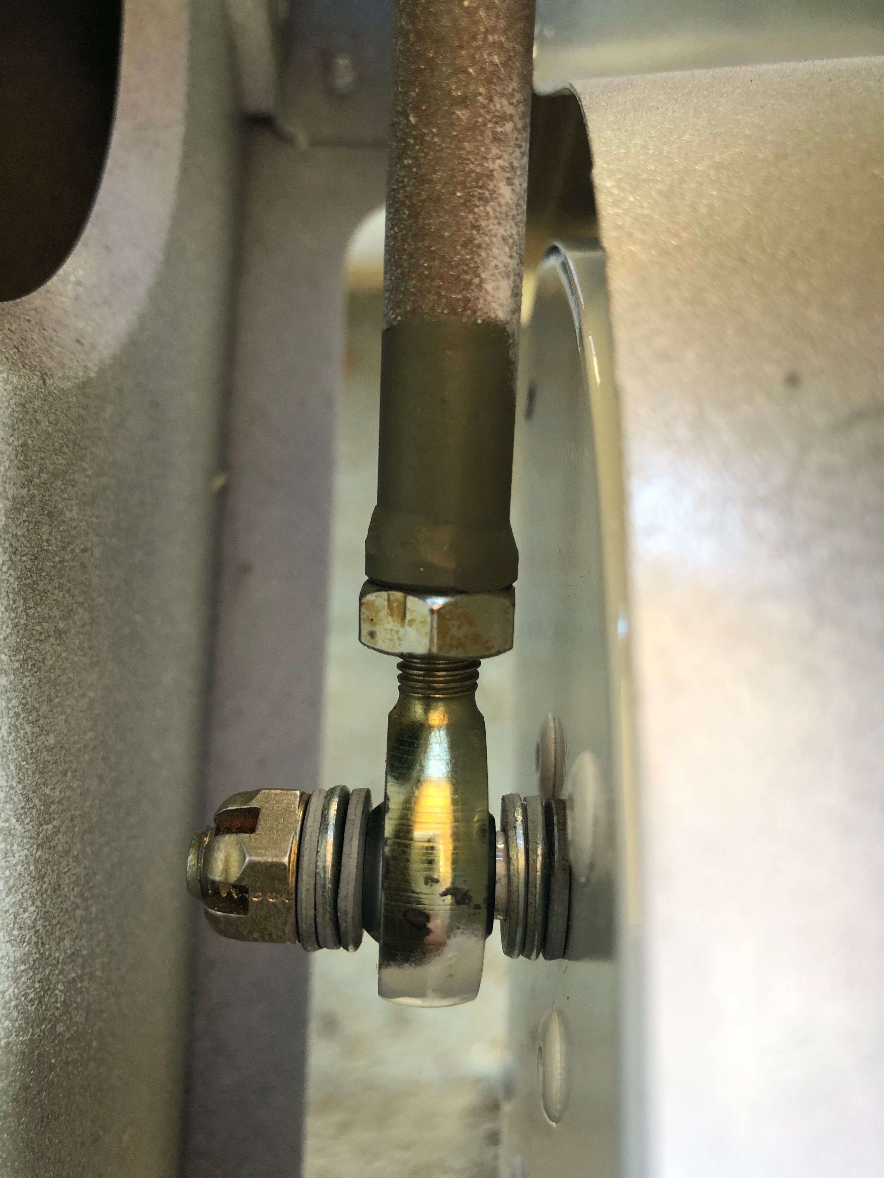
As I was packing up last night I noticed a wet patch under the front tyre. When I investigated I found a very small leak from two of the modified water pump pipes. Unfortunately there was no way round it, the pump will have to be removed, the pipes removed and resealed. A call to Tony Palmer revealed that there had been other cases of leaking and was put down to a loose fitting pipe. The solution is to cut the thread slightly further down the pipe so it’s a tight fit when at the correct angle. Karen came along to give me a hand.
The slight leak. Can’t ignore it, if it leaks with no pressure in the system it’ll certainly leak a lot more when the engine is running.So the coolant needs to be drained……so I can remove the pump. I’ve removed the pipes from the water pump, cleaned the thread but now have to order an 18mm die. I’ll use the die to cut a slightly longer thread.As I can’t do anymore on the water pump I though i’d Loctite the12 set screws, 4 on each blade and…… add some Torque Seal on the set screws to allow any movement to be identified. I know have to wait for the Die to come before I can finish off the water pump.
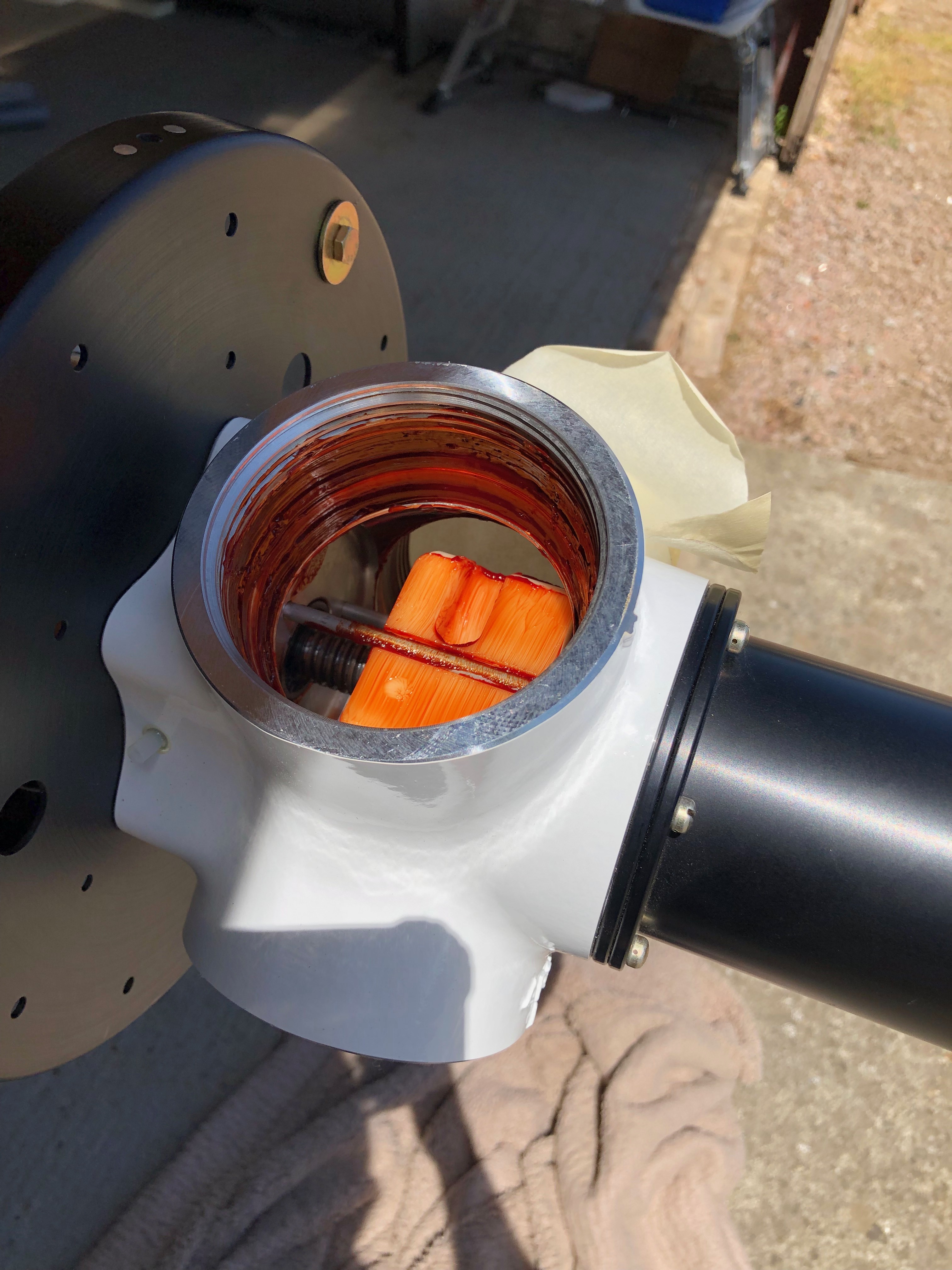
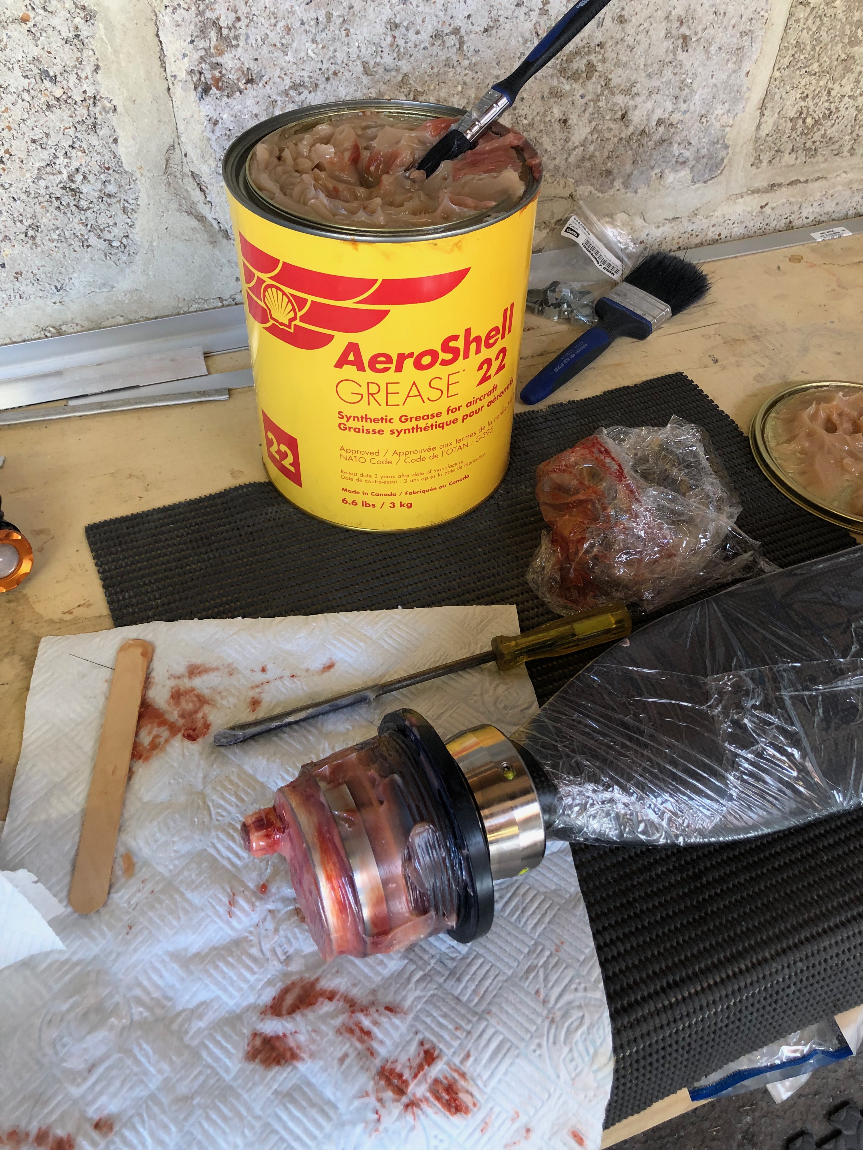
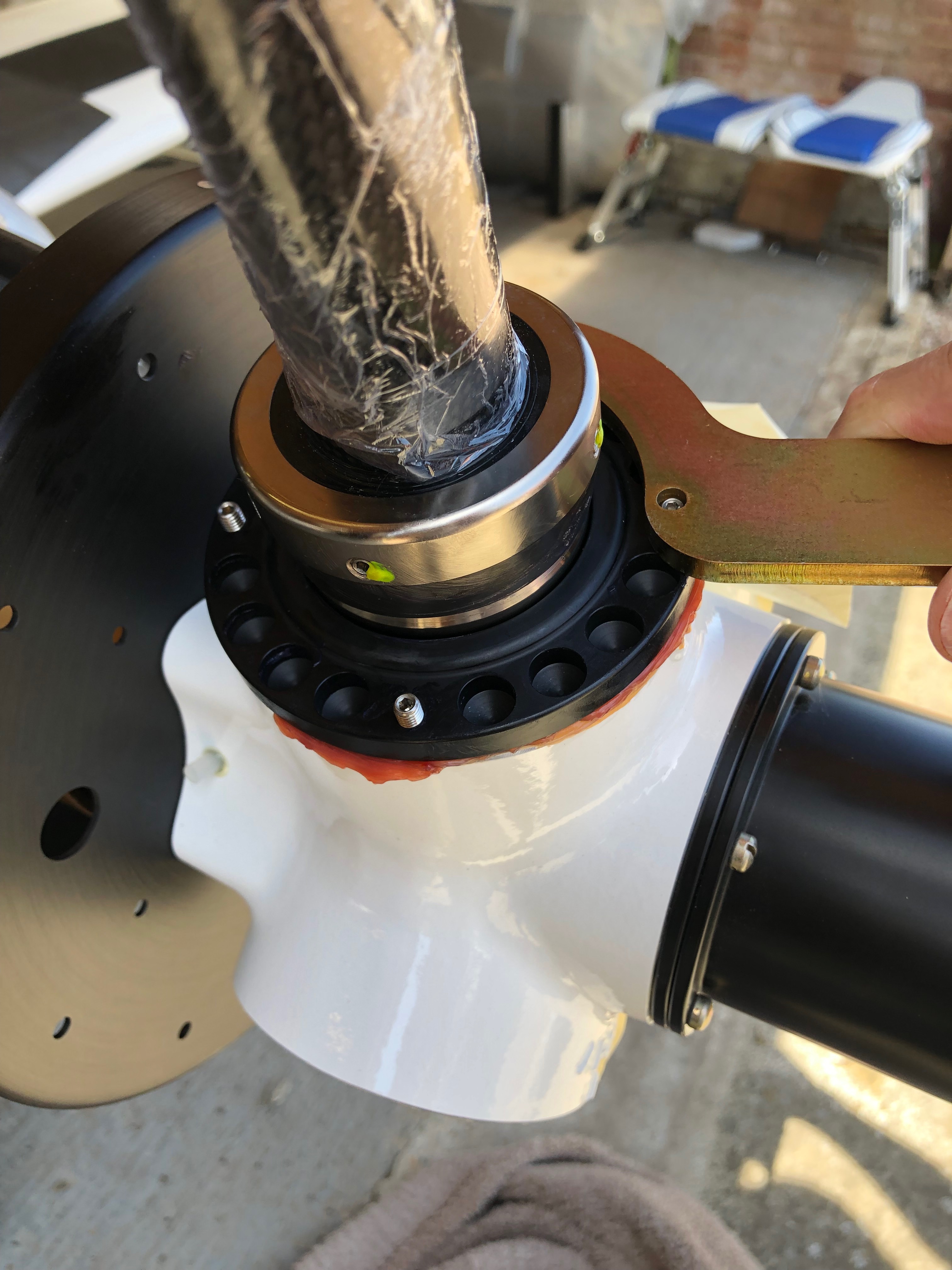
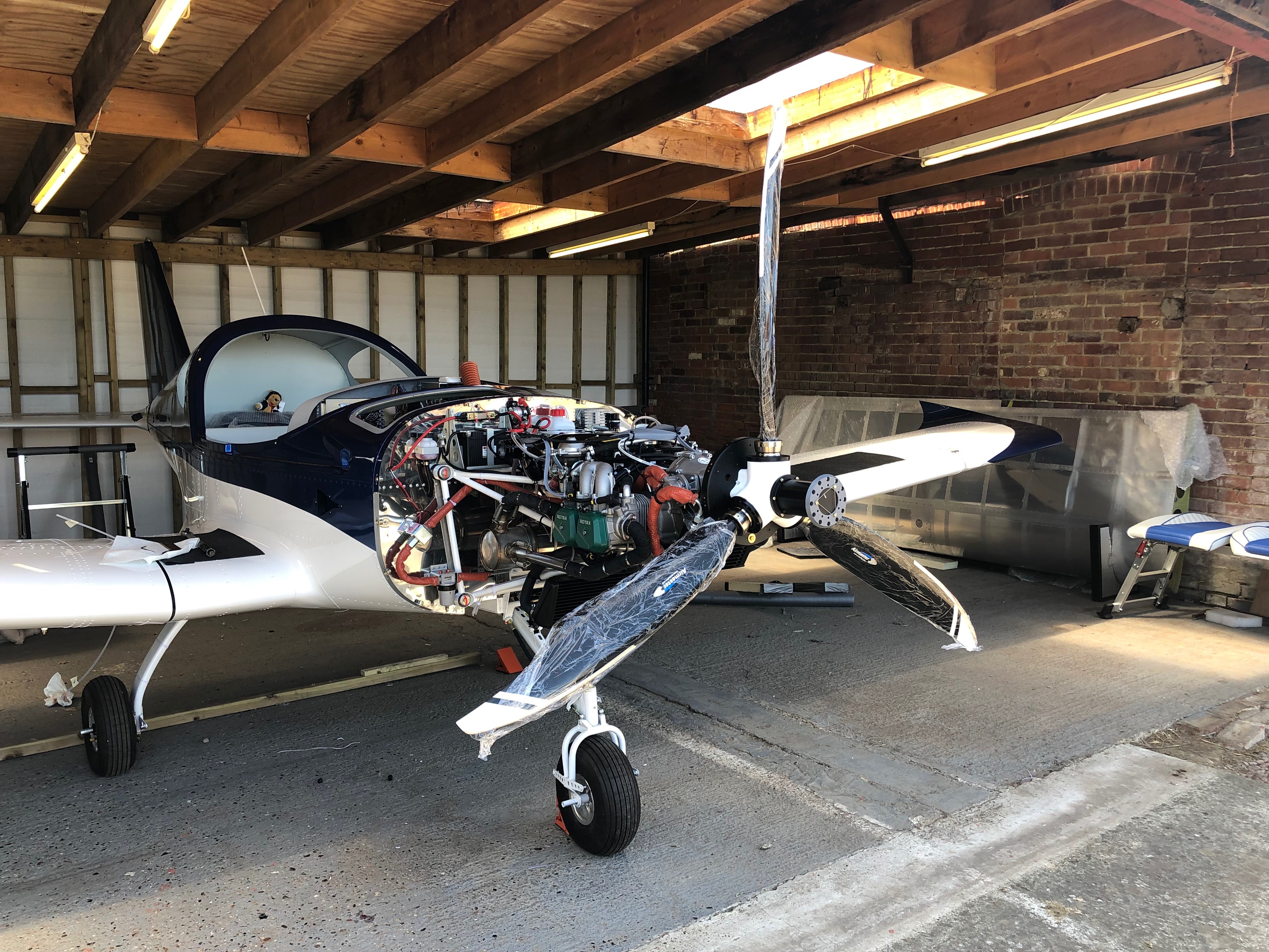
The main job today is to fit the propellor blades. Luckily the Aeroshell Grease that was supposed to have been delivered next Monday was delivered a couple of days ago so I can get on with it. Once fitted I can purge the oil system and add the antifreeze.
I had a call with CFS Aero who have now acknowledged that it would be a good idea to change the floats before I first fly the aircraft as Rotax have had a problem with sinking floats that leads to flooding of the engine and the possibility of engine failure. They will be sent in the post in the next couple of days. They have also confirmed that Halford OAT antifreeze is ok to fill the coolant system.
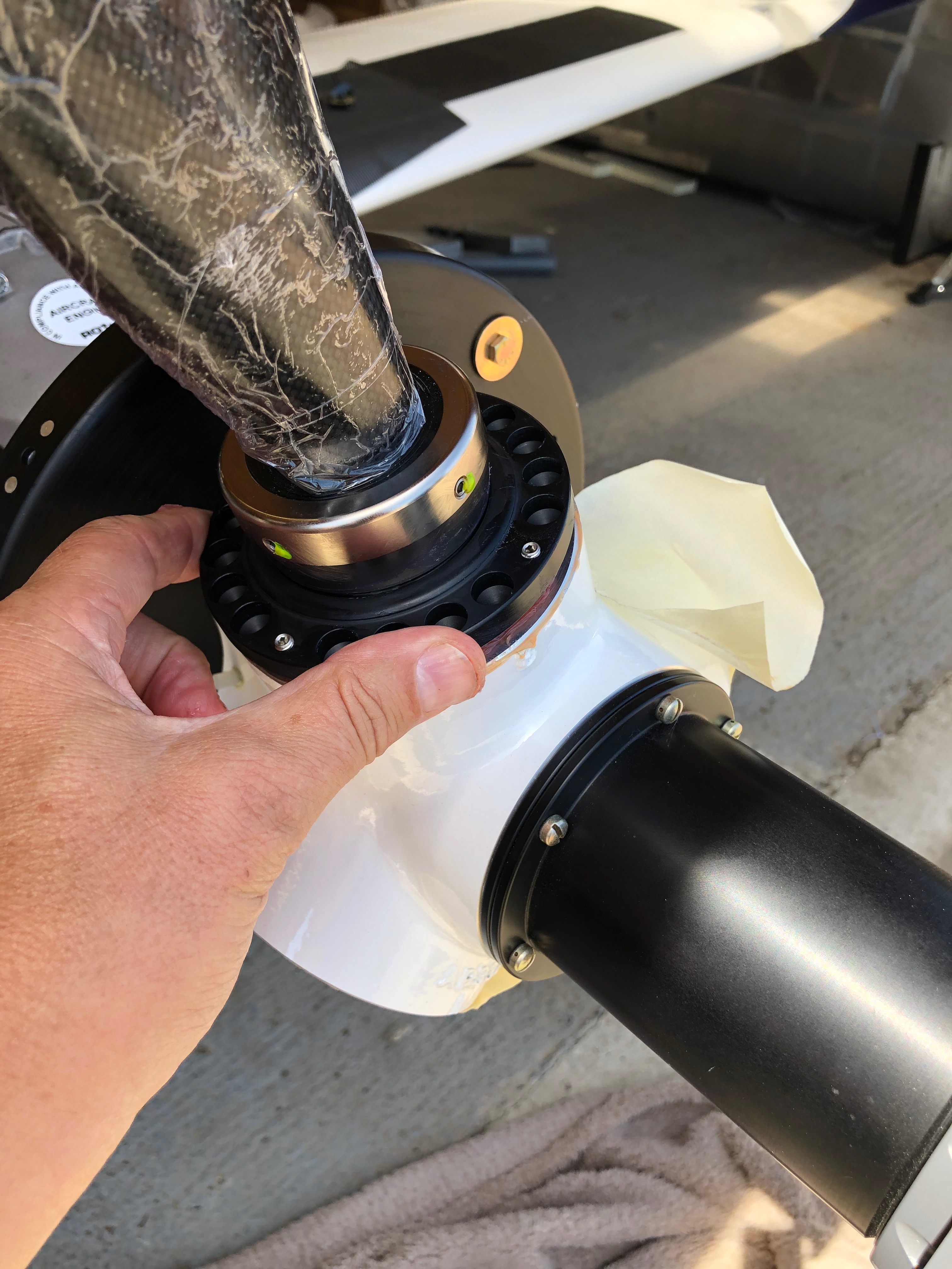
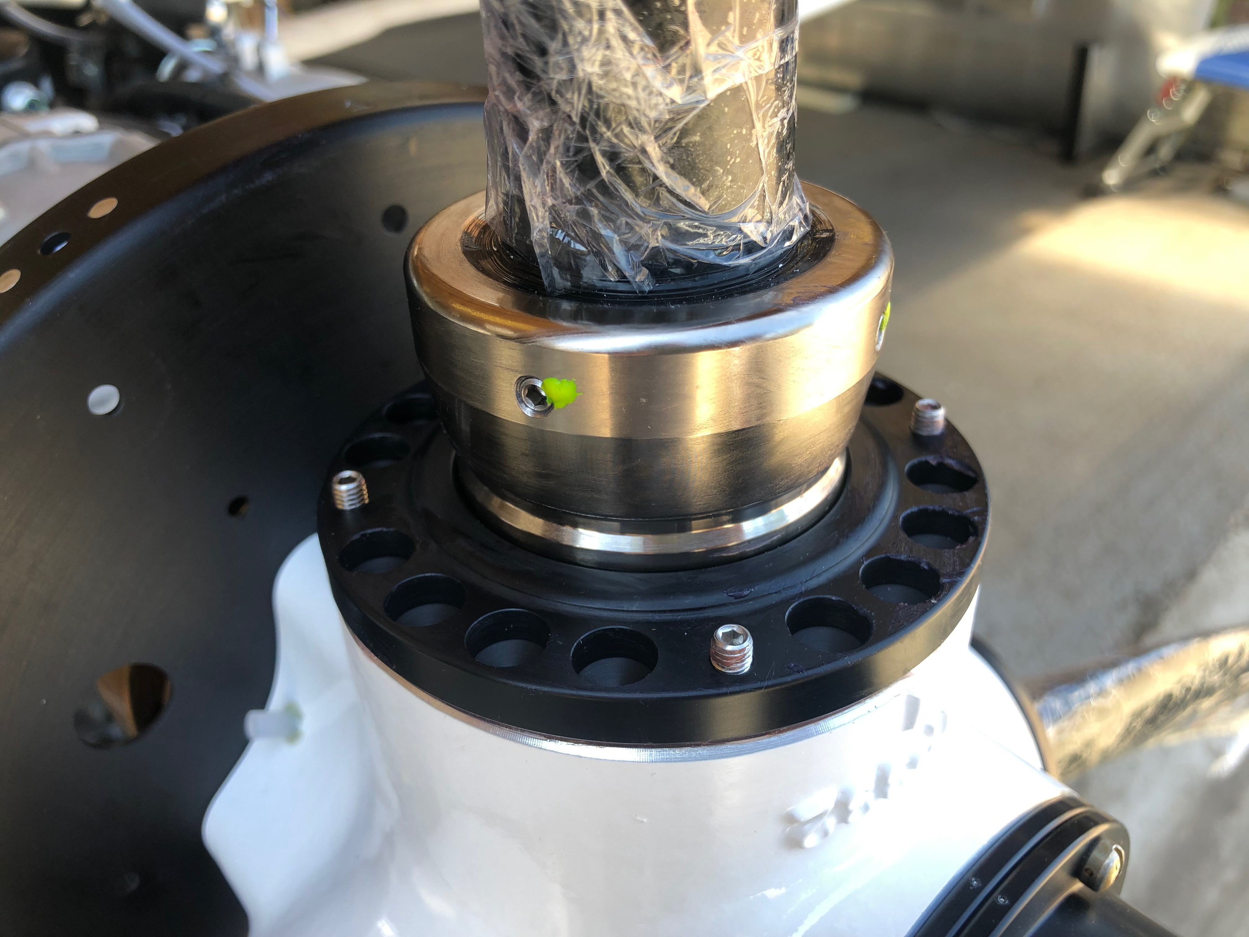
Once the protective seal has been removed it reveals the pitch change mechanism. It’s been greased after manufacture but needs a further coating as per a service bulletin.I think I may have ordered the wrong size tin of grease 🙂 It was at a bargain price which was cheaper than smaller tins. The hub is liberally coated with grease before being installed.Each blade is simply screwed in……the set screws are unscrewed to leave around 4mm showing.A special ‘C’ spanner is fitted on the set screws which is used to tighten to the specified torque setting using a torque wrench.Job done, looks quite good. A quick test of the pitch system confirms it’s working as expected. Now for the oil system purging and filling the coolant system which has taken a lot more than the 1 1/2 litres that Rotax advertise to fill the system so I’ll need to get some more tomorrow.
Music: Reverend And The Makers, Ian Brown and Razorlight.
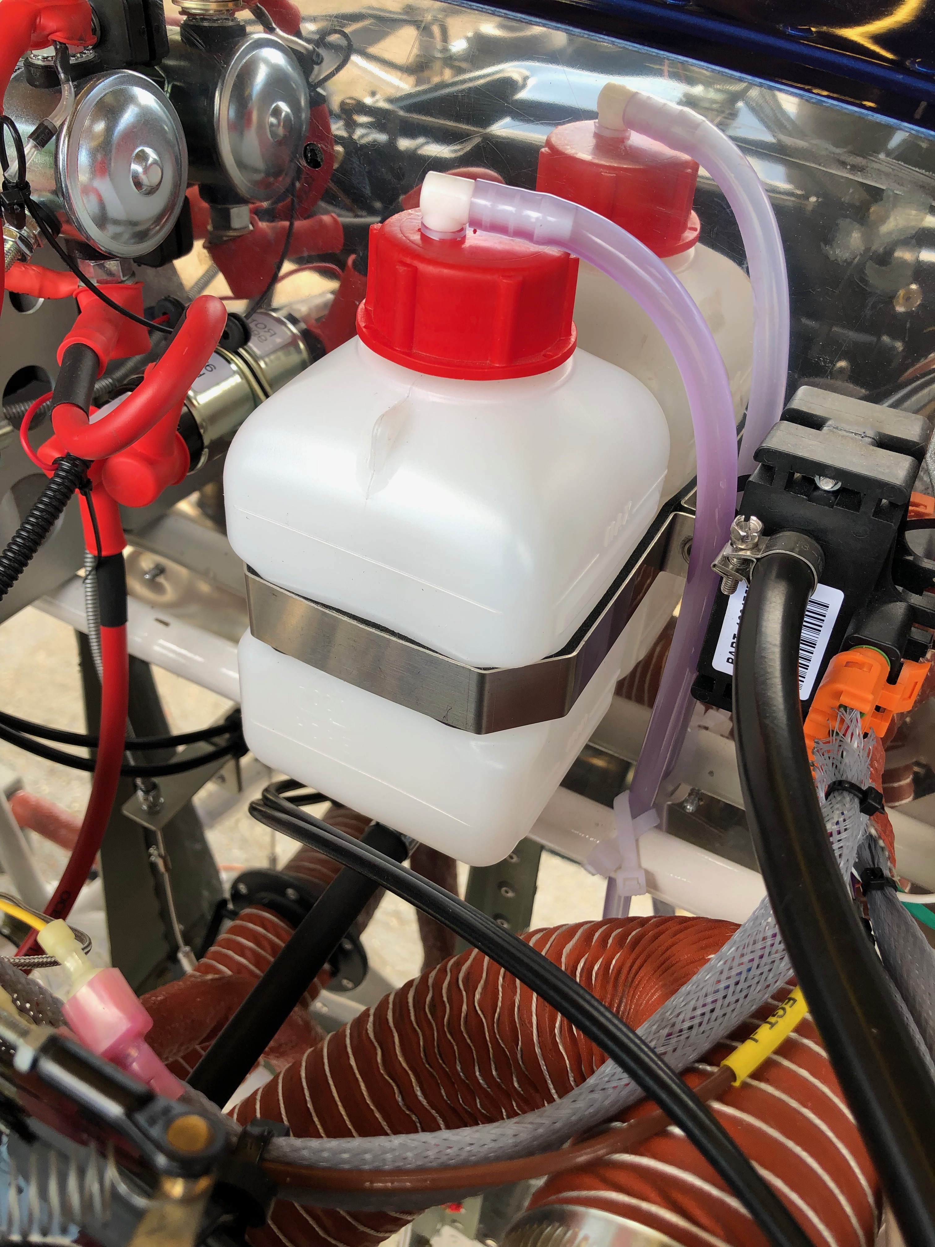
A few smaller jobs to do today including the last bit of wiring, wire locking the tailplane, adding a vent pipe to the coolant bottle and adjusting the flap operating arms.
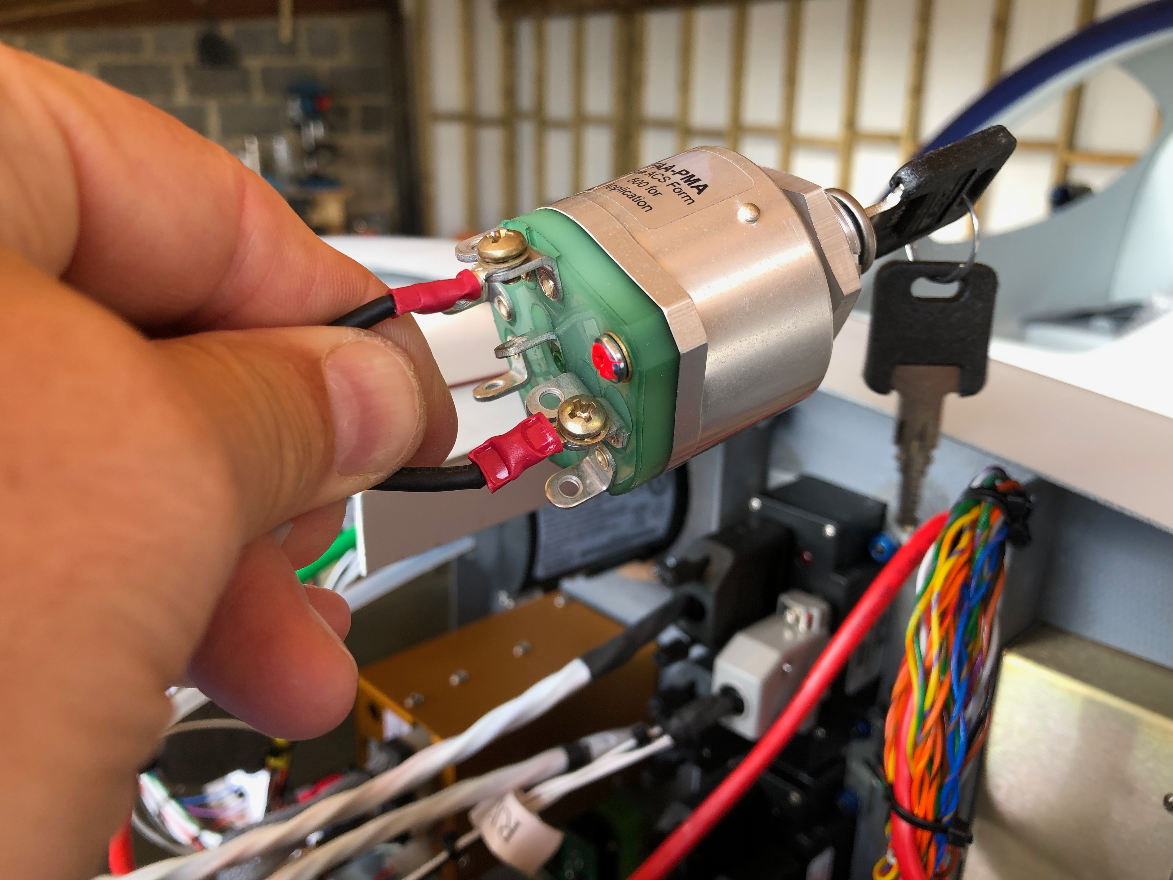
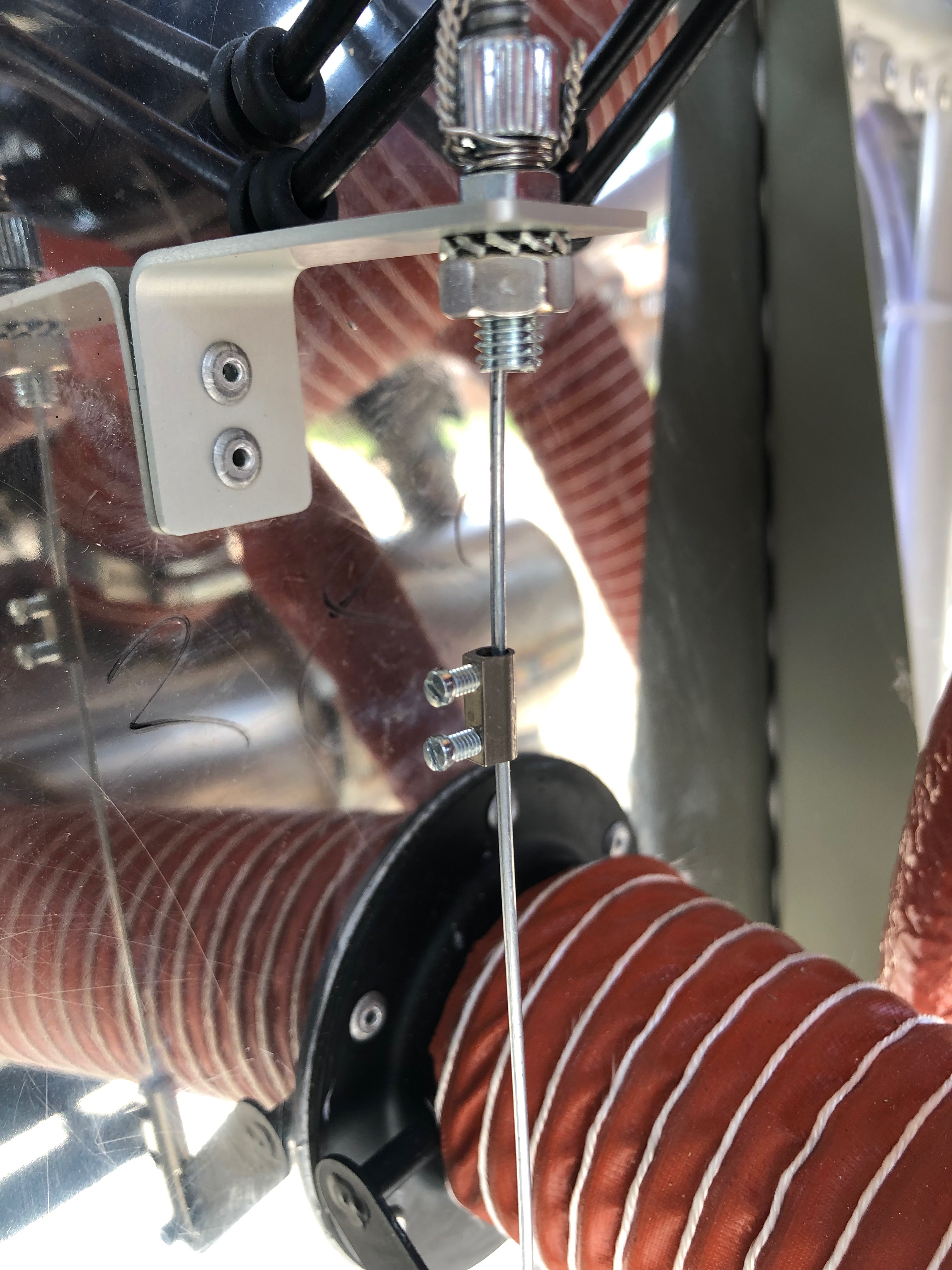
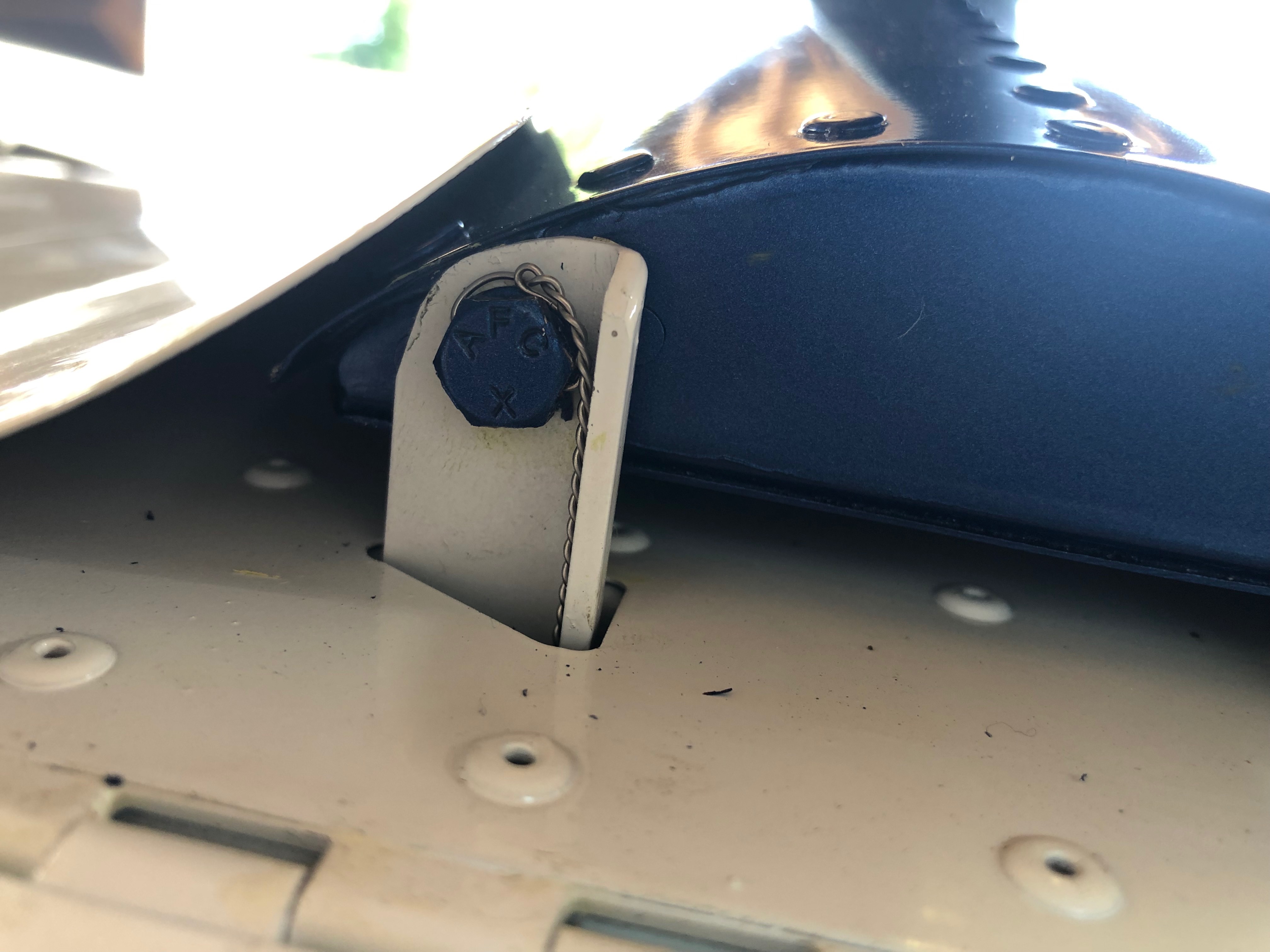
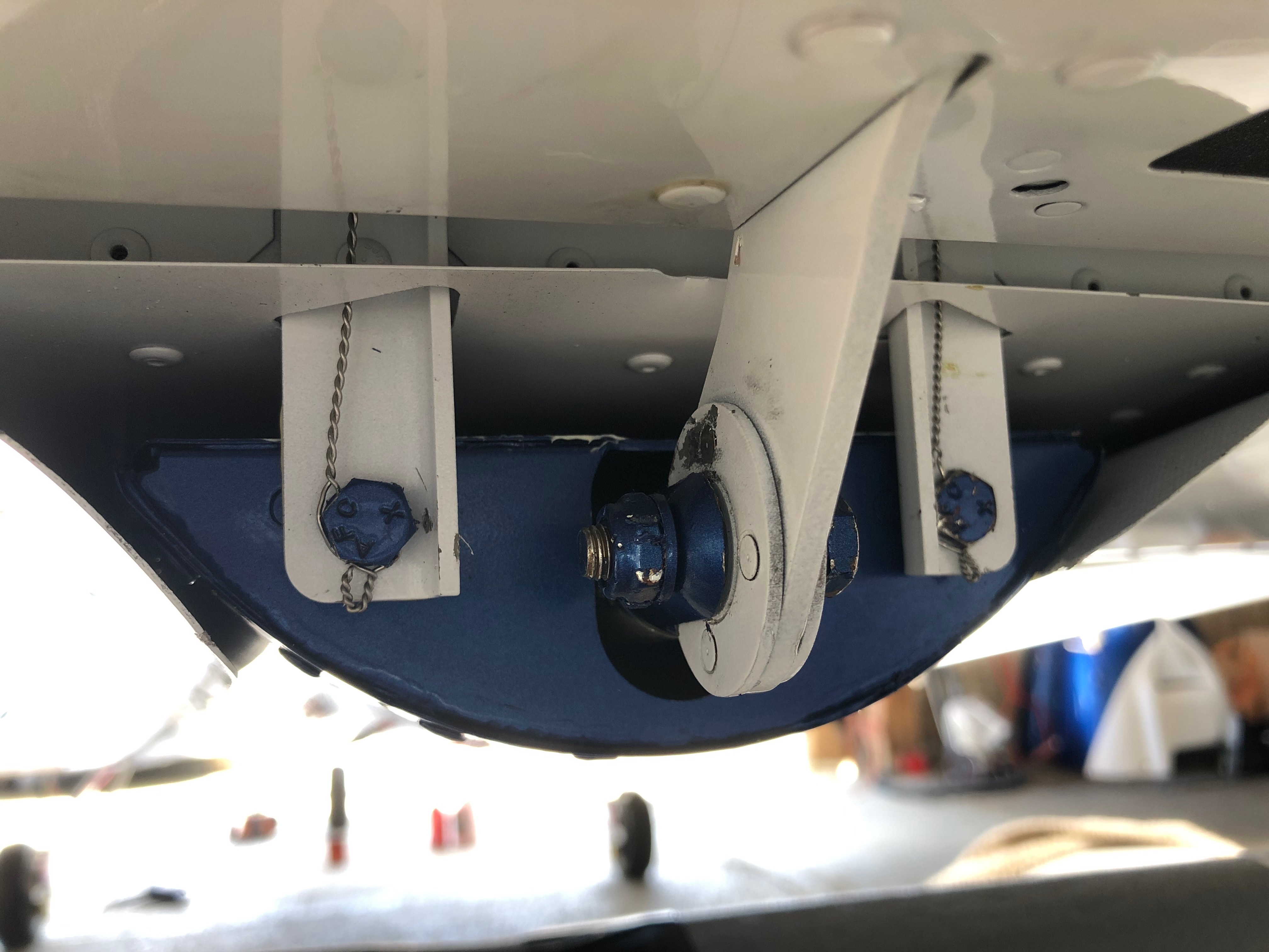
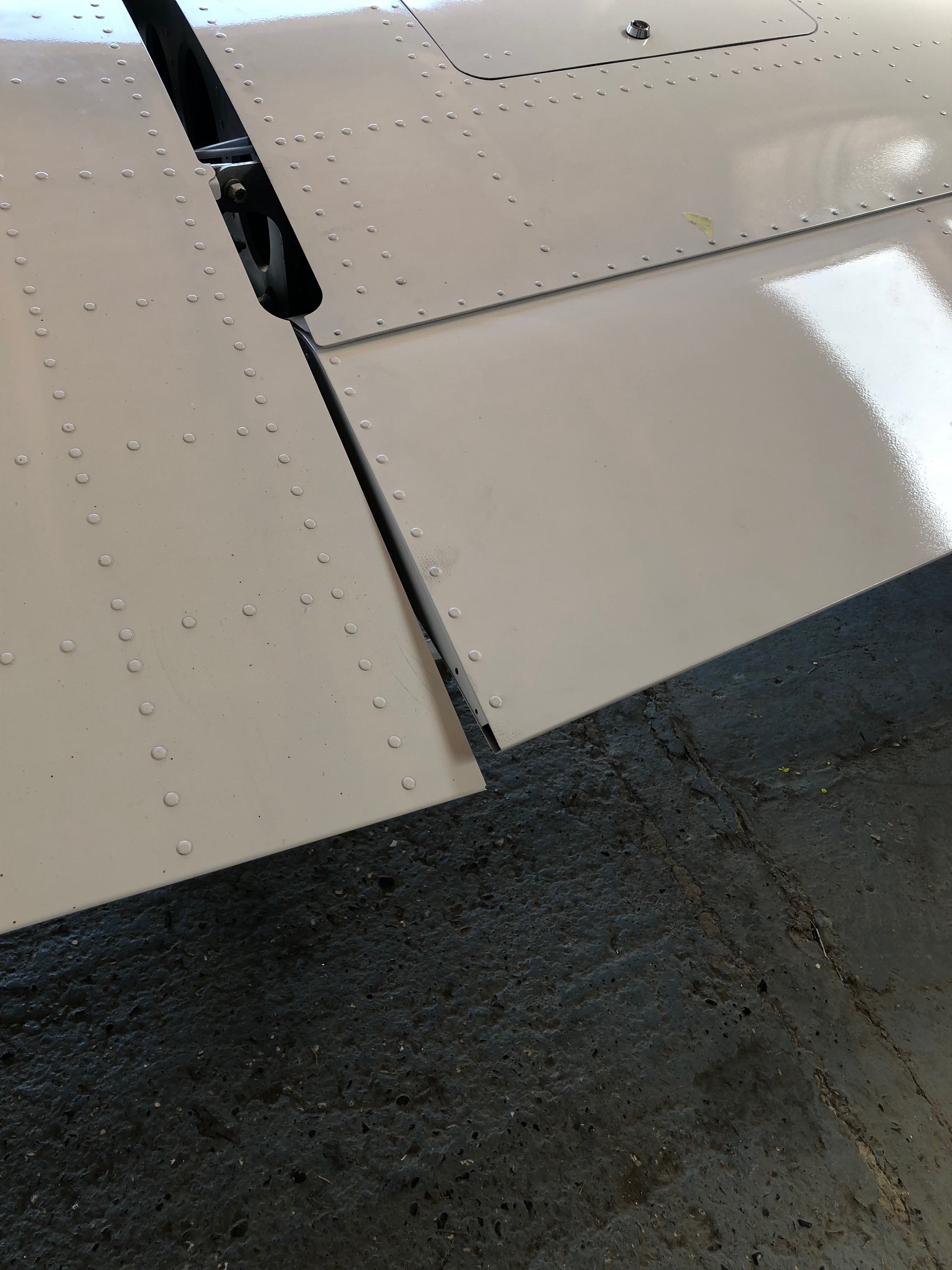
The ACS ignition switch requires 5 wires, Left and Right magnetos, battery, starter solenoid and ground. It uses 4mm ring connectors that are secured with screws and shake proof washers.The carb heat and heater controls require a positive stop to make sure you don’t pull the cable too far. I’ve used a ‘chocolate block’ with the insulation cut off……slid it on the cable and secured it with the 2 screws.The same was done for the heater control.I’ve added a breather in the coolant bootle and run the pipe down the firewall and out under the fuselage.Four bolts secure the tailplane and once torqued to the correct setting are wire locked to ensure they don’t undo.The wire locking is carried through from the top bolt and finished off around the bottom bolt.The flaps require adjusting to be flush with the trailing edge of the wing…The control rod arms have adjusters at either end and are adjusted equally before locking up.
Music: The Greatest Showman reimagined and Snow Patrol.
Finishing off the insulation installation, first fit of centre console, autopilot servo install and filling brake system with Aero Shell 41.
One quick job this morning now all the other pipes have been fitted is to run a piece of piping from the water expansion chamber to the water bottle.
I have been given templates for the insulation so I can cut them to size without too much effort.
Some notches, cuts and holes need to be made to make sure it sits properly on the firewall.
It’s a tight fit behind the rudder pedals which makes it difficult to handle once the backing paper has been removed.
The final pieces are fitted around the heated inlet.
The finished insulation, hopefully this should reduce noise from vibration of the firewall and the engine.
Now the servos brackets are in position the servos can be fitted. First the roll servo.
It’s very fiddly and would have been much easier to fit the servo to the bracket whilst it was out of the aircraft.
The pitch servo with the movement limiting bracket fitted which stops the motor running over centre. I still can’t finish the installation as there were items missing from the kit supplied to me – very frustrating as I can’t refit the controls until I fit the roll servo arm.
A first fit of the centre console in readiness for the fuel selector. Need to check with the instrument panel in place to check that the flap control cable is long enough to fit on the panel otherwise is will need to be mounted here instead which I would like to avoid.
After fitting the insulation need to reconnect and tighten the brake hoses before filling.
The brake fluid is filled from the bottom so some plastic pipe is wire locked onto the brake calliper nipple so stop it slipping off. The nipple is unscrewed to allow the fluid to flow into the calliper.
An oil can that has been thoroughly cleaned is filled with Aero Shell 41 and the plastic pipe is fitted to the nozzle.
The filling commences after releasing the park brake valve.
When the fluid reaches the brake oil bottle the brake calliper nipple is tightened and the process is repeated for the lefthand side brakes.
Filling complete but some air bubbles are present. They will need to be purged before use otherwise the brakes may not operate properly.
Today was spent mainly wiring up the aileron trim motor, installing the port strobe before starting on the starboard wing landing light.
One little job to do today was to install an overflow pipe from the water expansion tank to the water bottle mounted on the firewall.
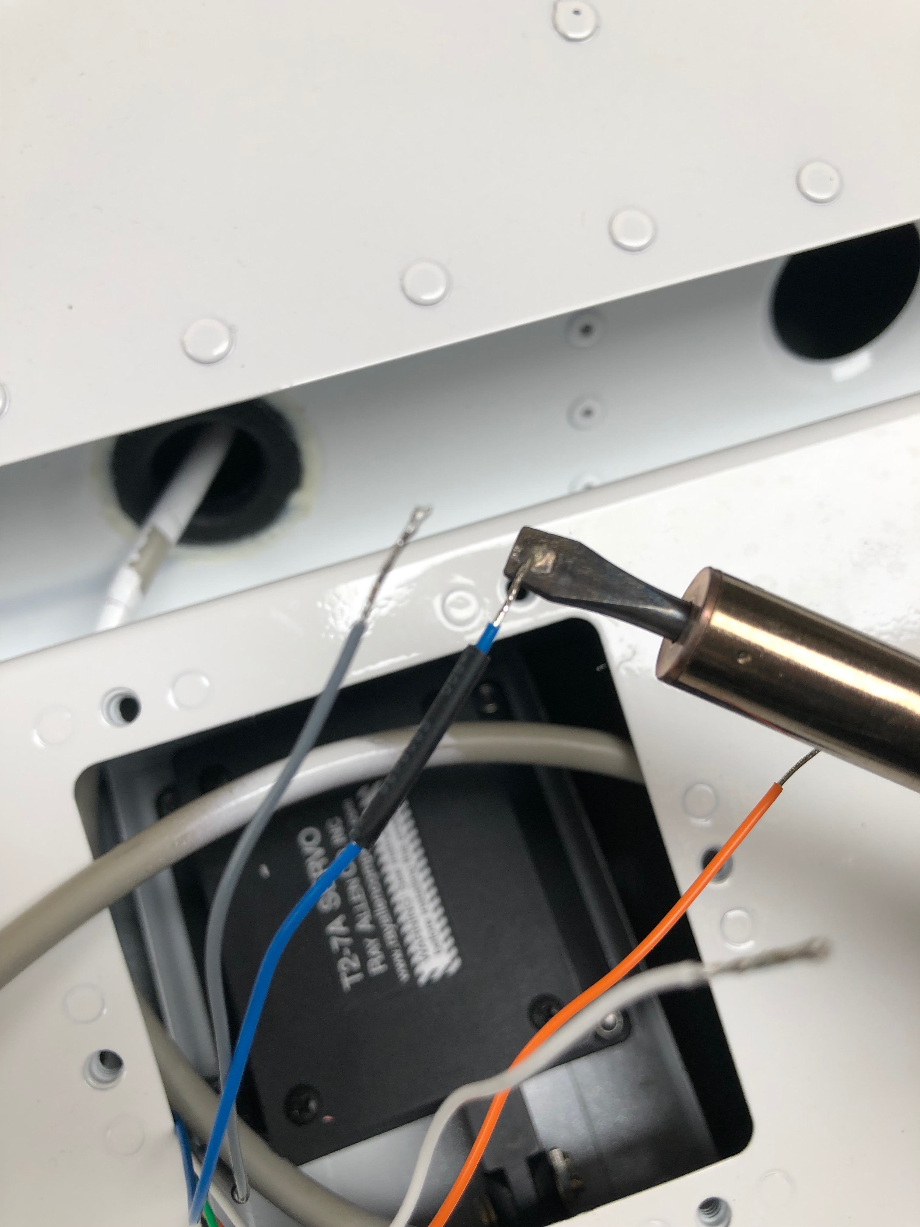
The aileron trim motor is connected to the wire installed in the wing. The ends are stripped and tinned.
Heat shrink tube is slid onto the wires before the soldering is done to make sure that they are well insulated.
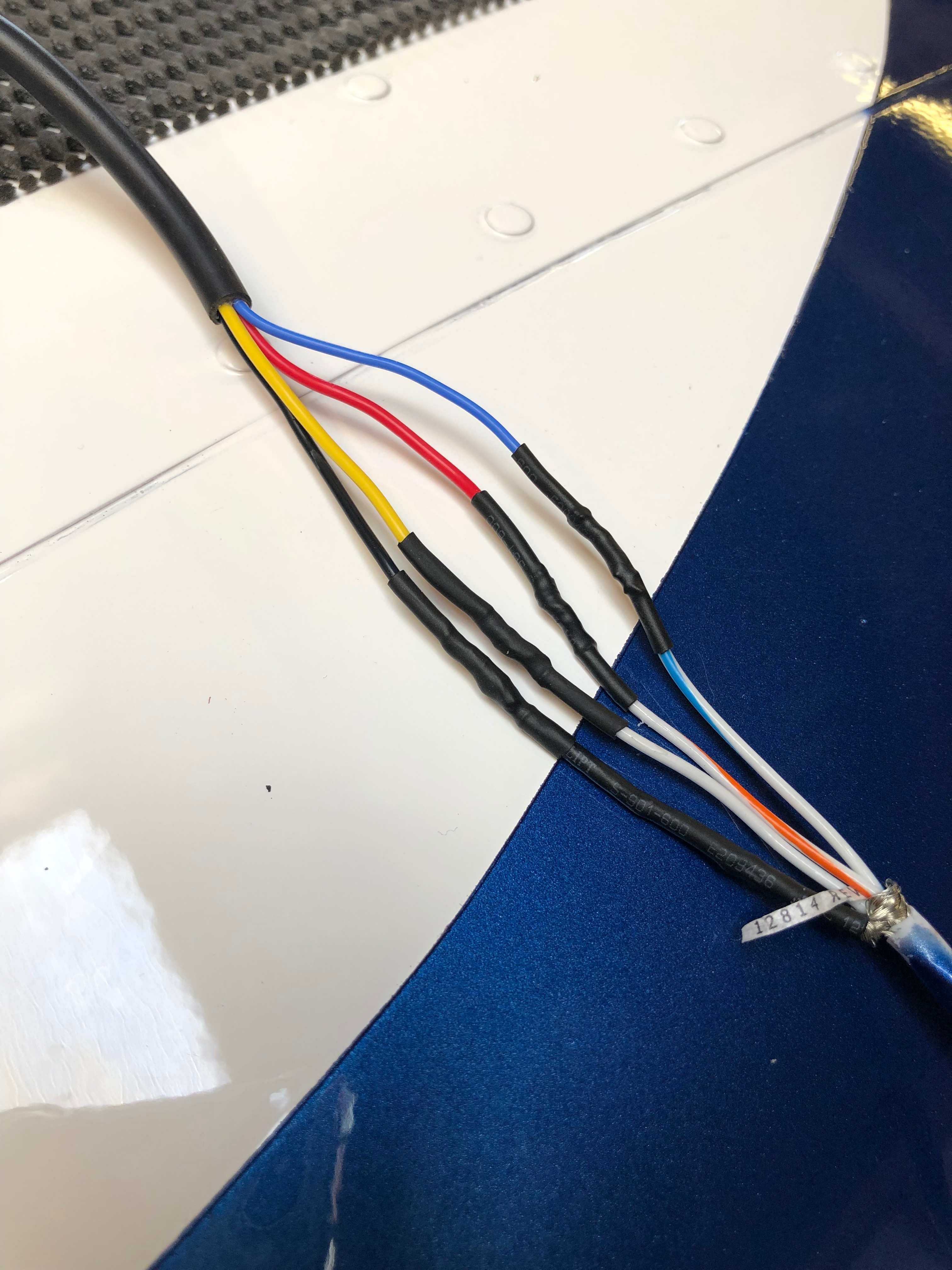
The colours don’t match between the trim motor and the wing wire so that will have to be documented in the aircraft wiring diagram.
A heat gun is used to shrink the tube over the wires and then a bigger piece (yellow tubing in picture) is slid over all the connections.
The wire is kept in place to stop it moving in operation with a spot of glue.
The strobes are next . Very important to mount the correct one on the correct side. Red is being installed on the left wing.
The same method is used to solder and secure the wire joints.
The strobe position is not marked so it’s important to get the right angle. I haven’t got any M3 rivnuts so will have to get some and do this tomorrow.
So the right wing is put on stands and I can now start on the landing lights and strobes for this wing. The pitot/AOA probe is installed on this wing but I don’t have the mount as it’s with Farry. So a 5 hour trip is required on Monday to get that and the most of the rest of the outstanding items.
The spade connectors are crimped and inserted into the connector block.
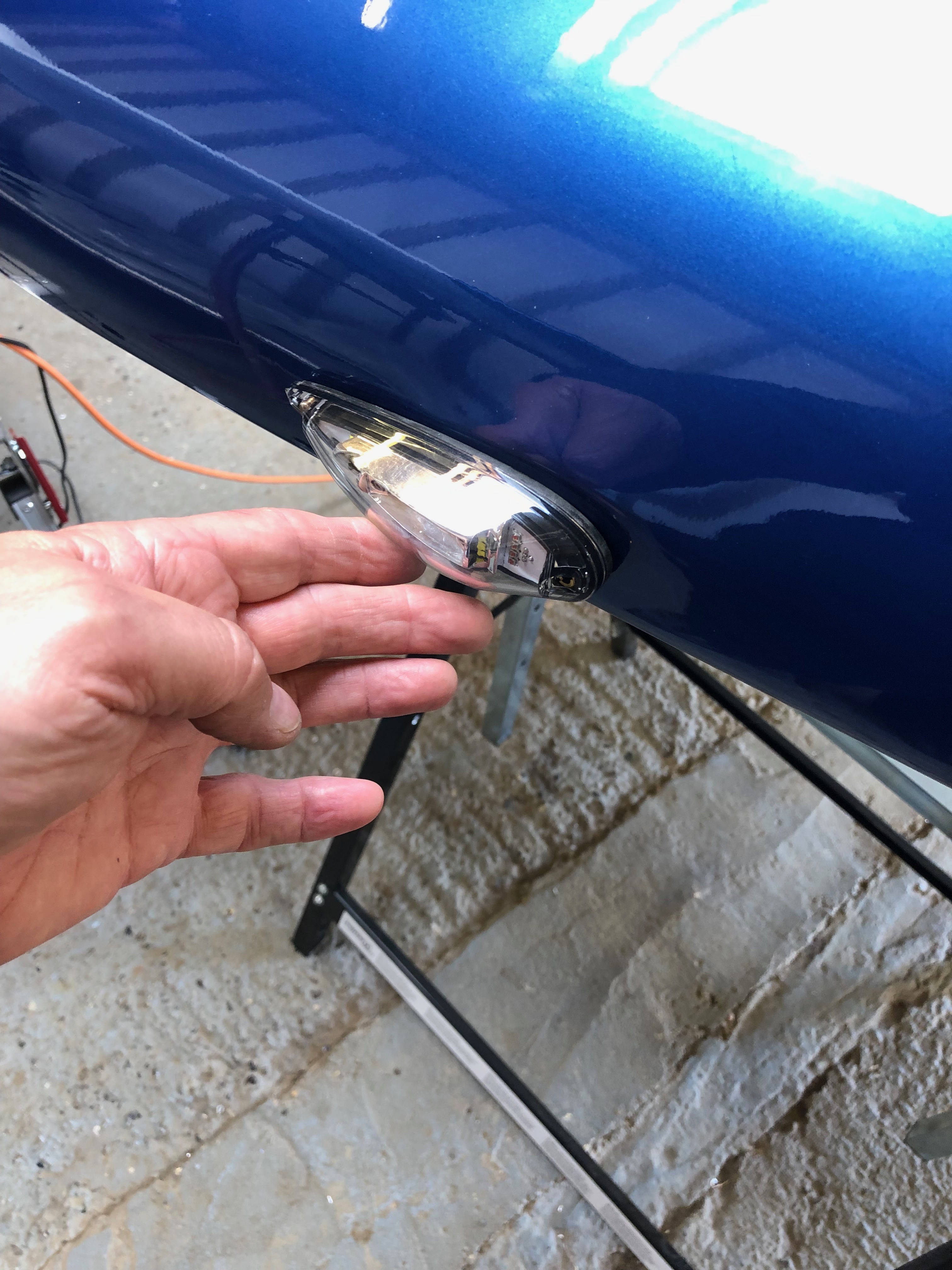
The landing light is installed. It’s upside down as the wing is upside down!
The installed landing light ready for the cover which I’ll do tomorrow now as I’ve run out of time.
Now I’ve received the water thermostat I can finish the water system, install the EGT sensors and complete the exhaust system.
Thermostat, hoses & clips for install.
The thermostat is fitted behind the expansion tank.
The hoses are attached…
and the radiator bottom support bracket is installed…
Once the radiator is fully installed I can check the cowls fit properly.
As you can see there is some trimming that needs to be carried out to make sure the cowl doesn’t foul the radiator.
Looks ok from the front.
The exhaust seems to clear the cowl however another check will be made before final assembly. The gascolator is located on the opposite side to the exhaust pipe and requires a hole to be drilled which will enable fuel checks to be carried out before flight.
The installed thermostat with just a ‘stand off’ to be fitted to make sure it doesn’t rub against the adjacent engine mount.
Now the cowl fitting has proven All the clips are fitted – job done.
I purchased a Kavlico EMS kit so the EGT sensors need to be installed.
A 3.2mm hole needs to be drilled in the rear exhaust downpipes 4″ from the flange.
Once the hole is drilled and sensor fitted it is held in place with the supplied, modified jubilee clip. The sensor has a ‘collar’ that ensures that the hole is sealed.
The downpipes are re-fitted and re-wrapped, securing in place with stainless steel ties.
To ensure the springs don’t fall and cause a runway hazard if they fail in service they are wire locked. Tomorrow I will fill the centres of the springs with heat resistant silicone which reduces any resonance from the springs.
A few smaller jobs, including exhaust wrapping, sensor fitting and cable oiling ahead of fitting the water thermostat that I finally received today.
The landing lights come with a couple of spade connectors that need to be crimped on…
and then slipped into the connector block. I’ll need to do the same thing when I come to install the LEDs into the wing.
The MAP sensor is fitted to the firewall in a suitable position making sure that the plug don’t foul one another.
The space between the water bottle and regulator seems to work well.
The front exhaust pipes covered in exhaust wrap and secured in place with stainless steel ties.
There’s several cables that need to be installed later in the build. Unlike the throttle cables these aren’t lined so require some lubrication.
Received at last! Good ol’ Parcel Force have had this since the 5th March but never left a card. It’s lucky I asked for an update on delivery from Silent Hektik otherwise I’d still be waiting. This is the 3rd time Parcel Force have completely screwed up on a delivery to me – I will never use them again!
Following the build of my Bristell NG5 Kit No. 382 Registration G-MLSY