I’m expecting the registration to arrive today and some G6 cutting liquid. I’ve also designed and ordered the stainless steel identification plate which will hopefully be with me on Monday or Tuesday.
Today’s the day to refit the water pump, it’s had plenty of time to cure so fingers crossed that it’s sealed properly this time. I’ll also finish fitting the glare shield.
Also Bristell have been in touch to say that they have a pair of rear windows in the correct colour so I need to pick them up at some point soon…
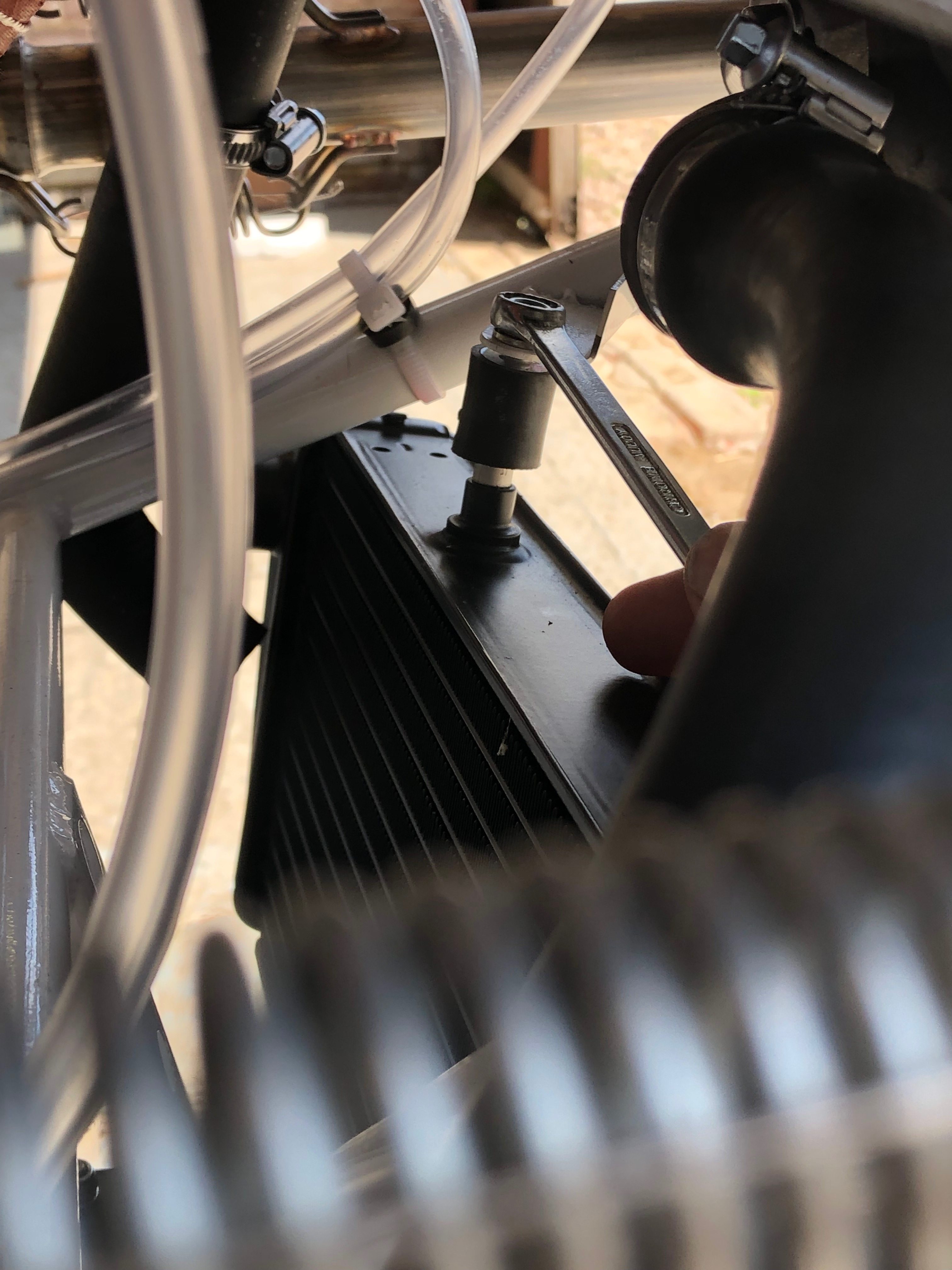
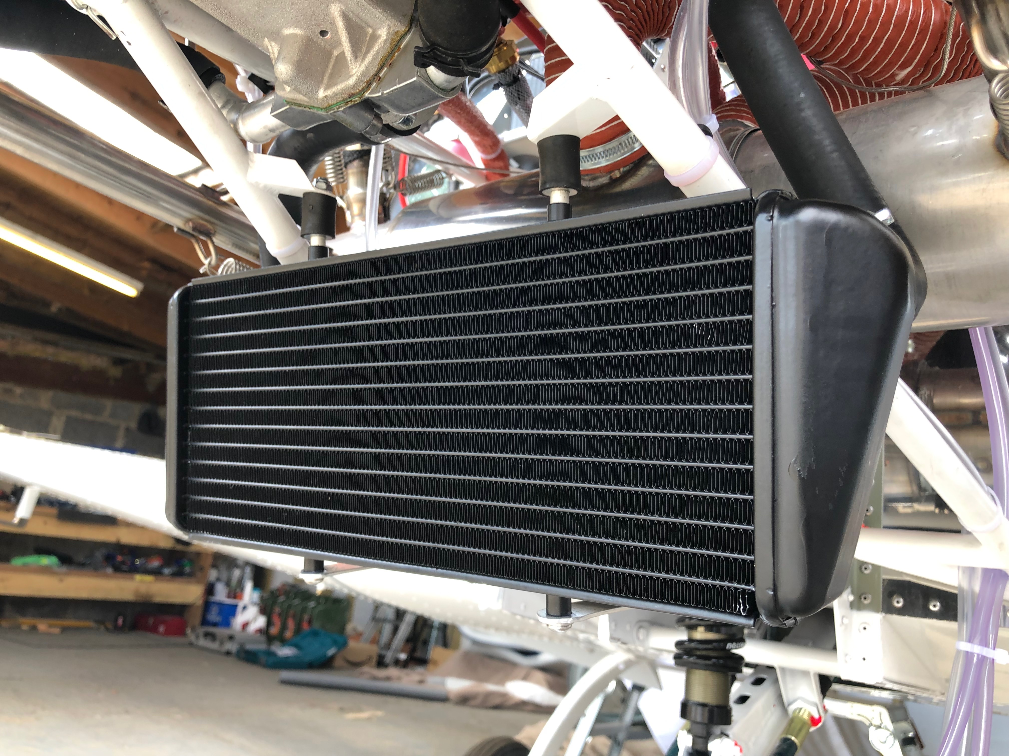
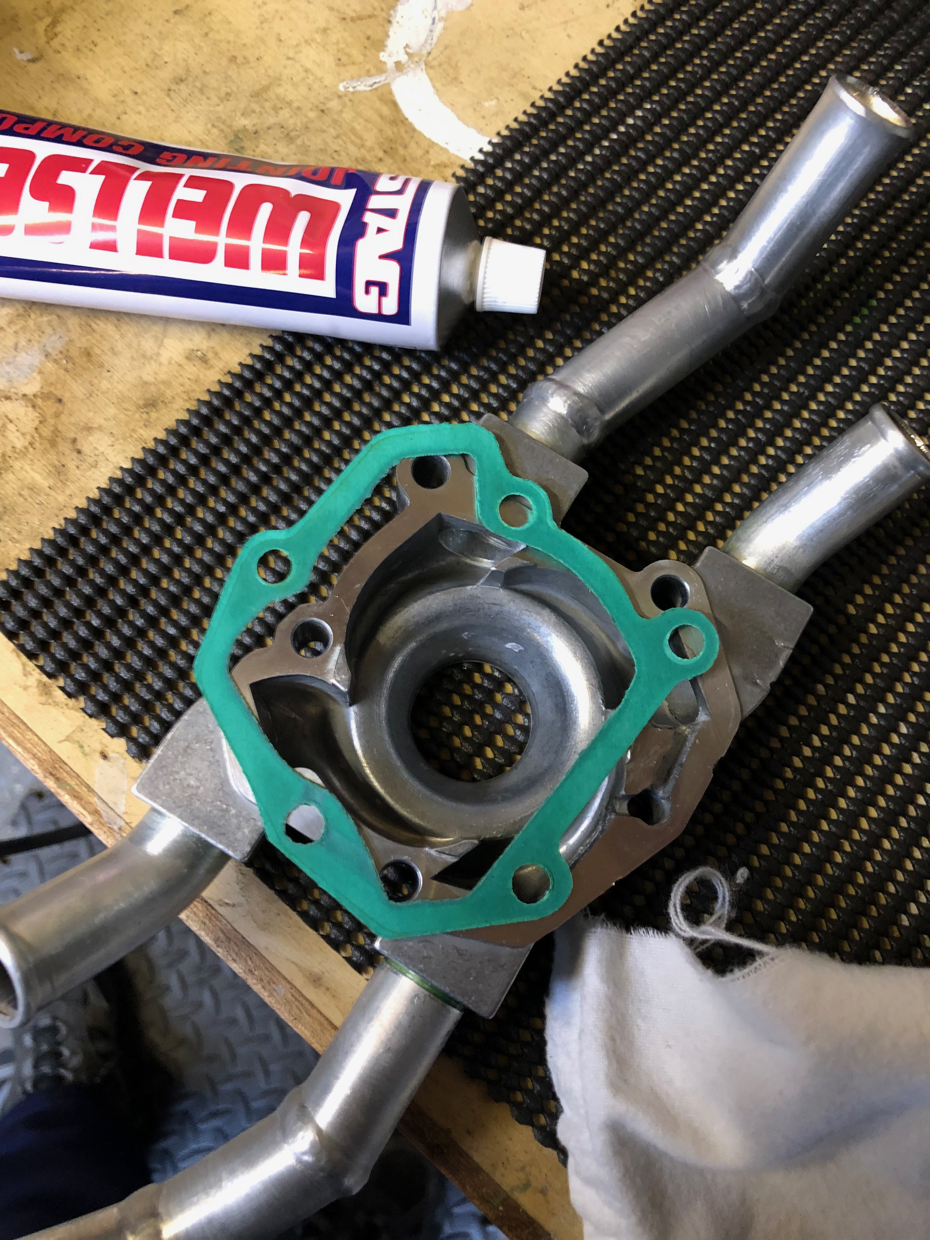
I’ve cleaned up the gasket ready for the refit.After running a thin bead of Wellseal around the pump mating surface it’s bolted back on and the bolts are torqued up.The radiator is remounted……and all the pipes reconnected,The water system has been refilled and I’ll leave it for the weekend to see if the reseal has been successful.Next is to finish fitting the glare shield. It’s a tricky job as there is only a very narrow band to secure it too but it has to be done ‘blind’. I’ve decided the best way to do this is to position the glare shield and use a very small drill to drill a pilot hole and just mark the fuselage skin. Removing the glare shield reveals if I’ve drilled in the correct position. If so I can open it up and fit the Rivnut. Seven screws are used to secure the glare shield and I’m considering using a couple more to secure the shield to the instrument panel. That’s a job for Monday.
Music: Lightening Seeds, The Beautiful South, Gerry Rafferty
Feel like I’m going backward as I need to do some remedial work to the water pump and replace the carburettor floats. But I have a few other things that I’ll do today which will get me back on track. I will o order the registration vinyls (that I have left far too late) and I’ll also be fitting the seatbelts.
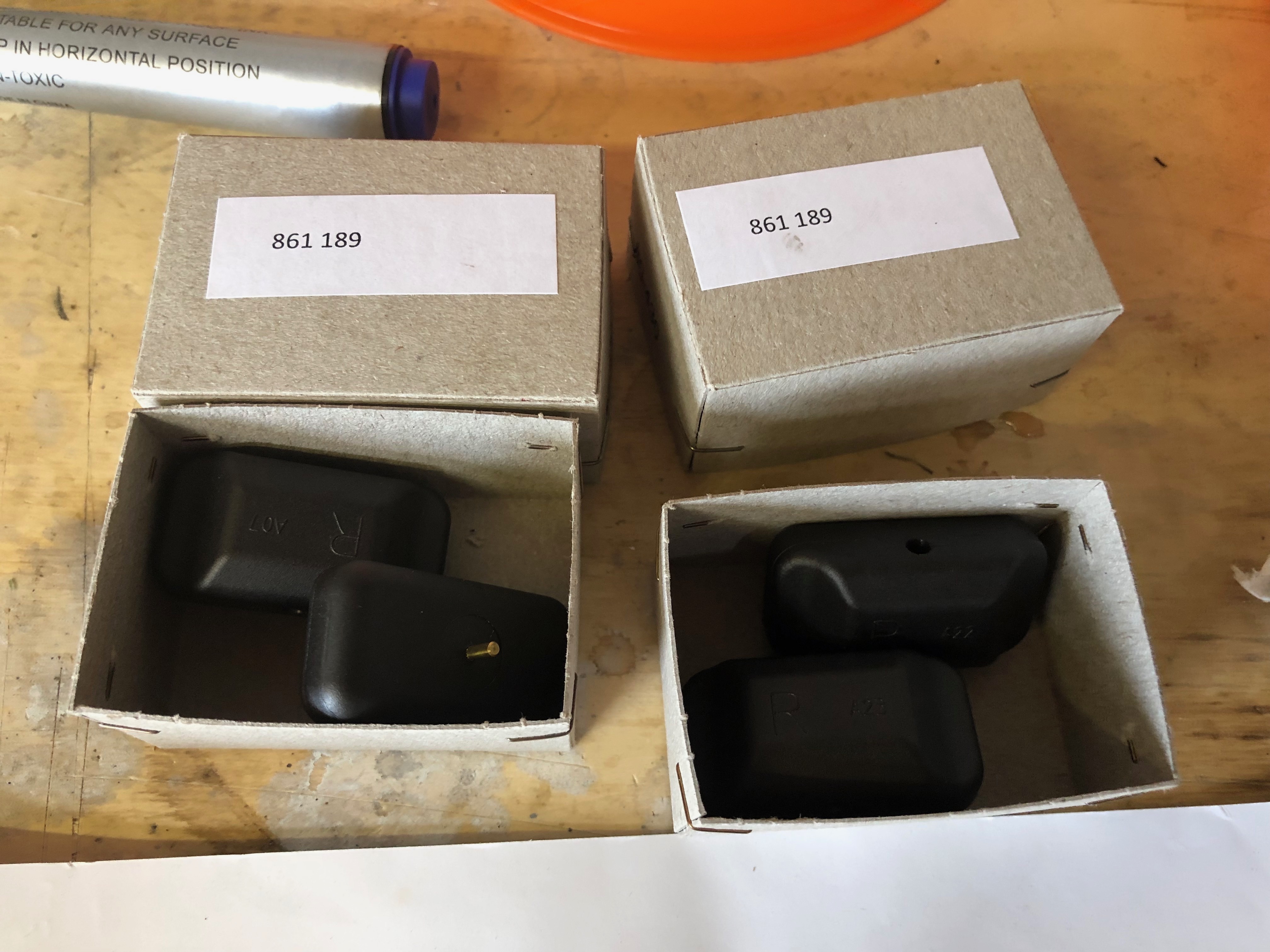
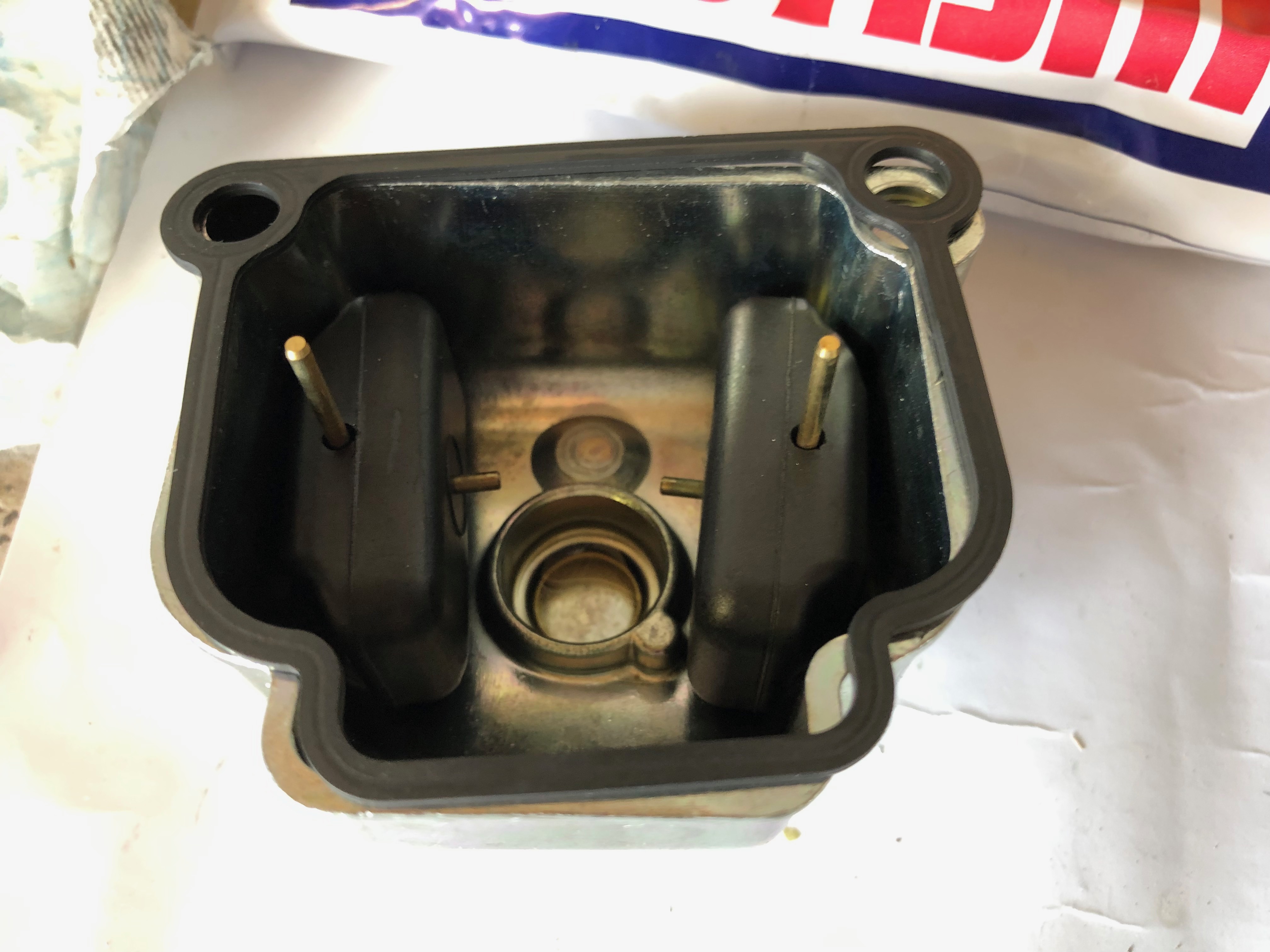
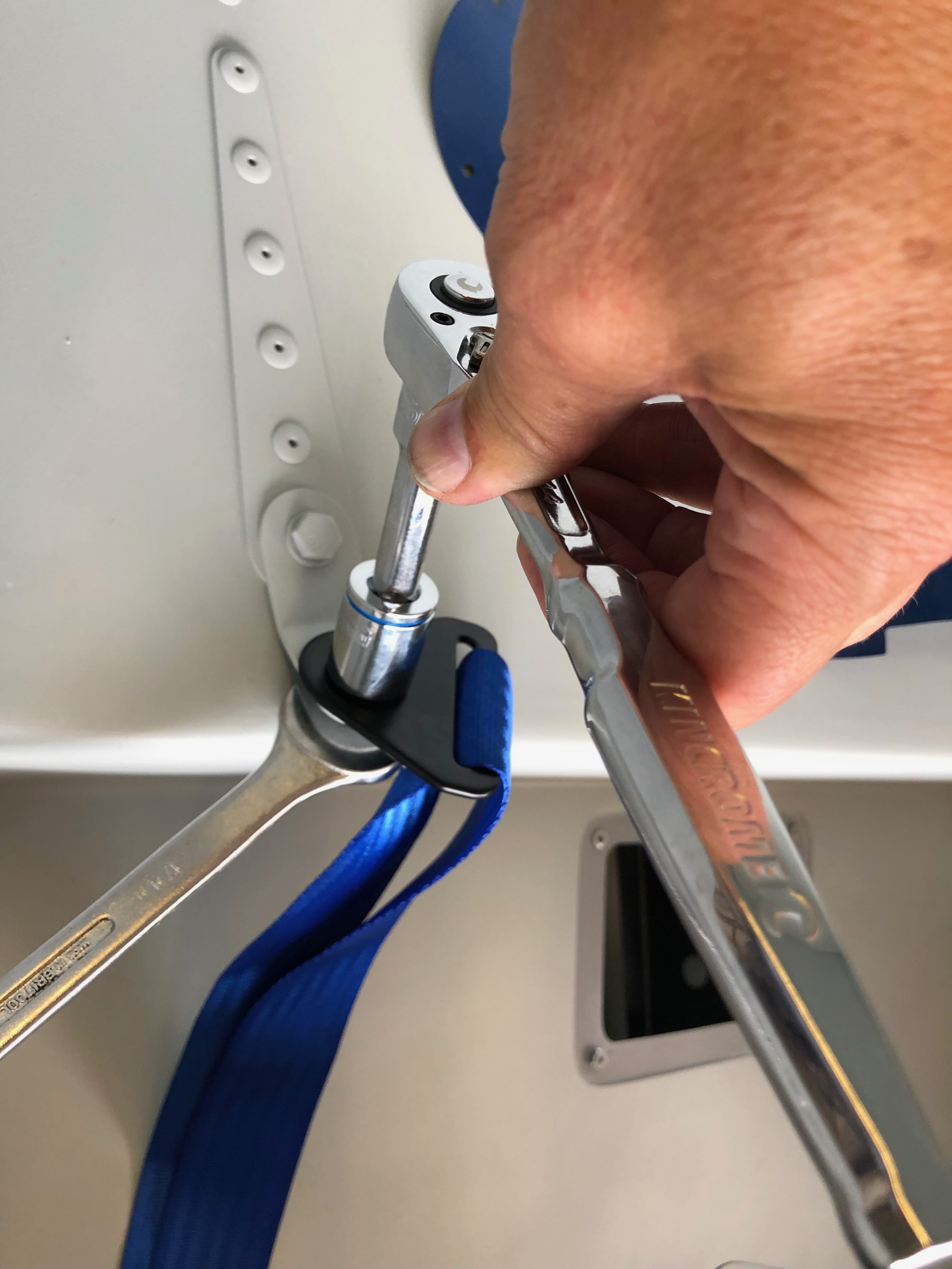
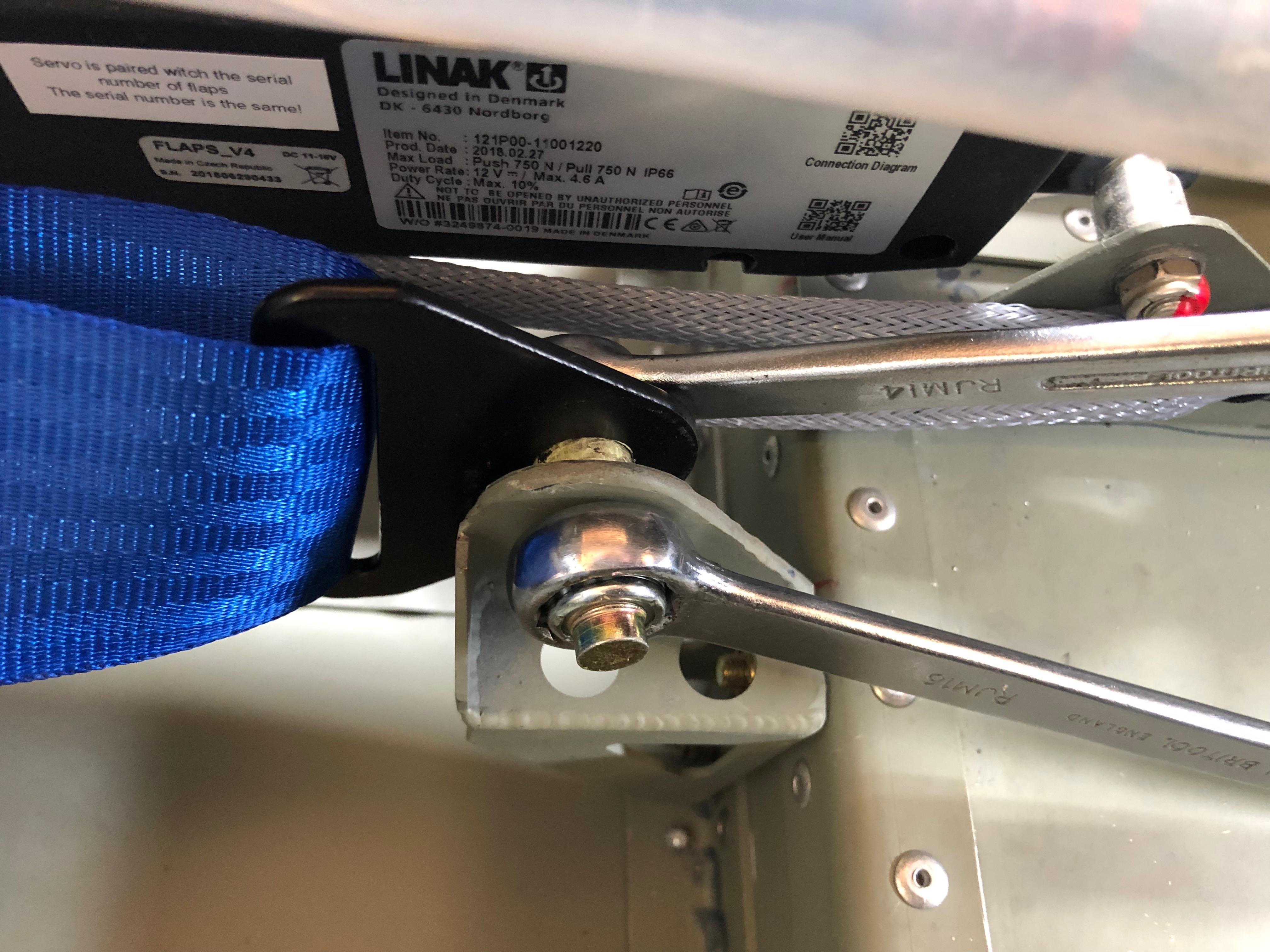
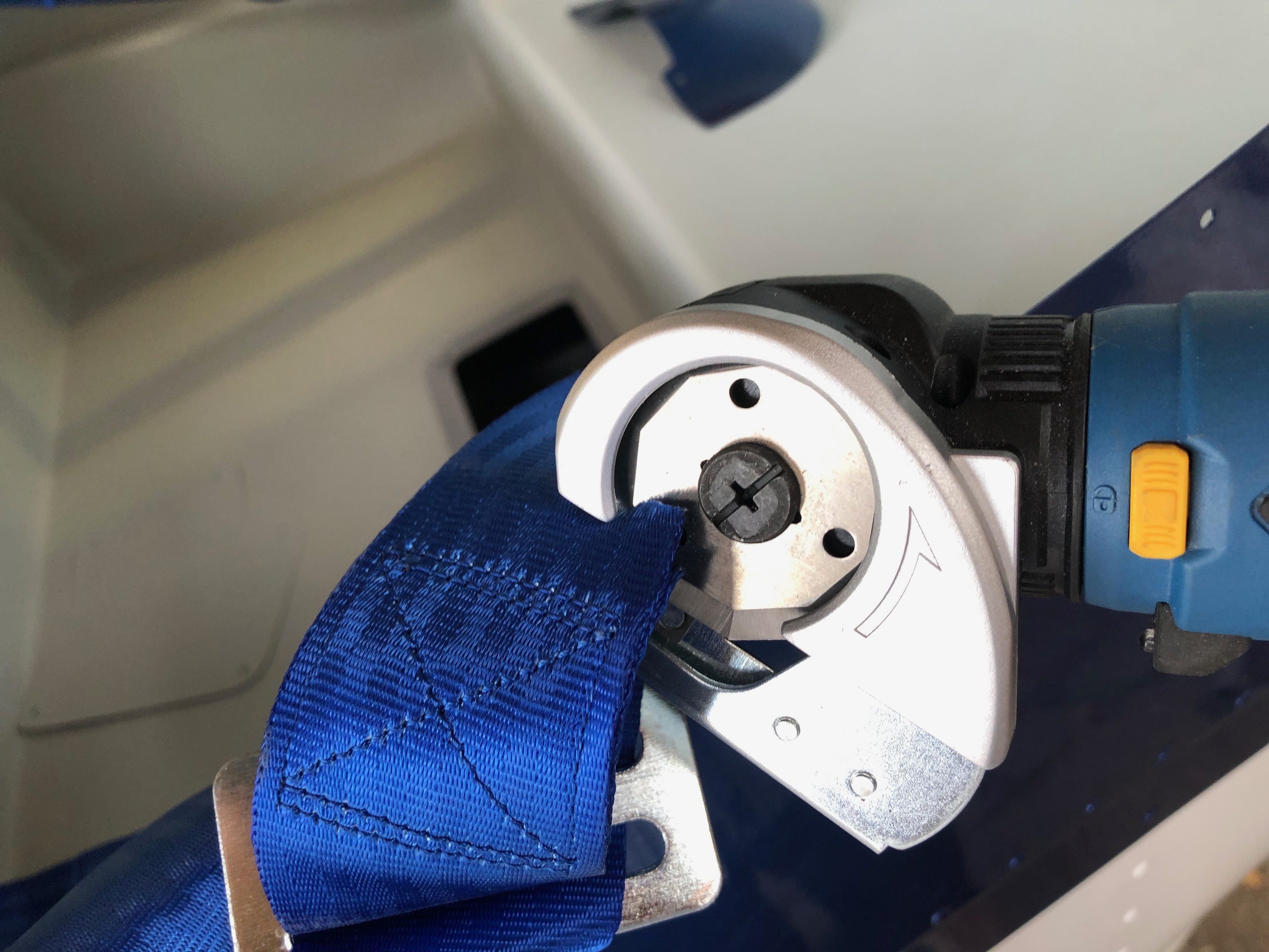
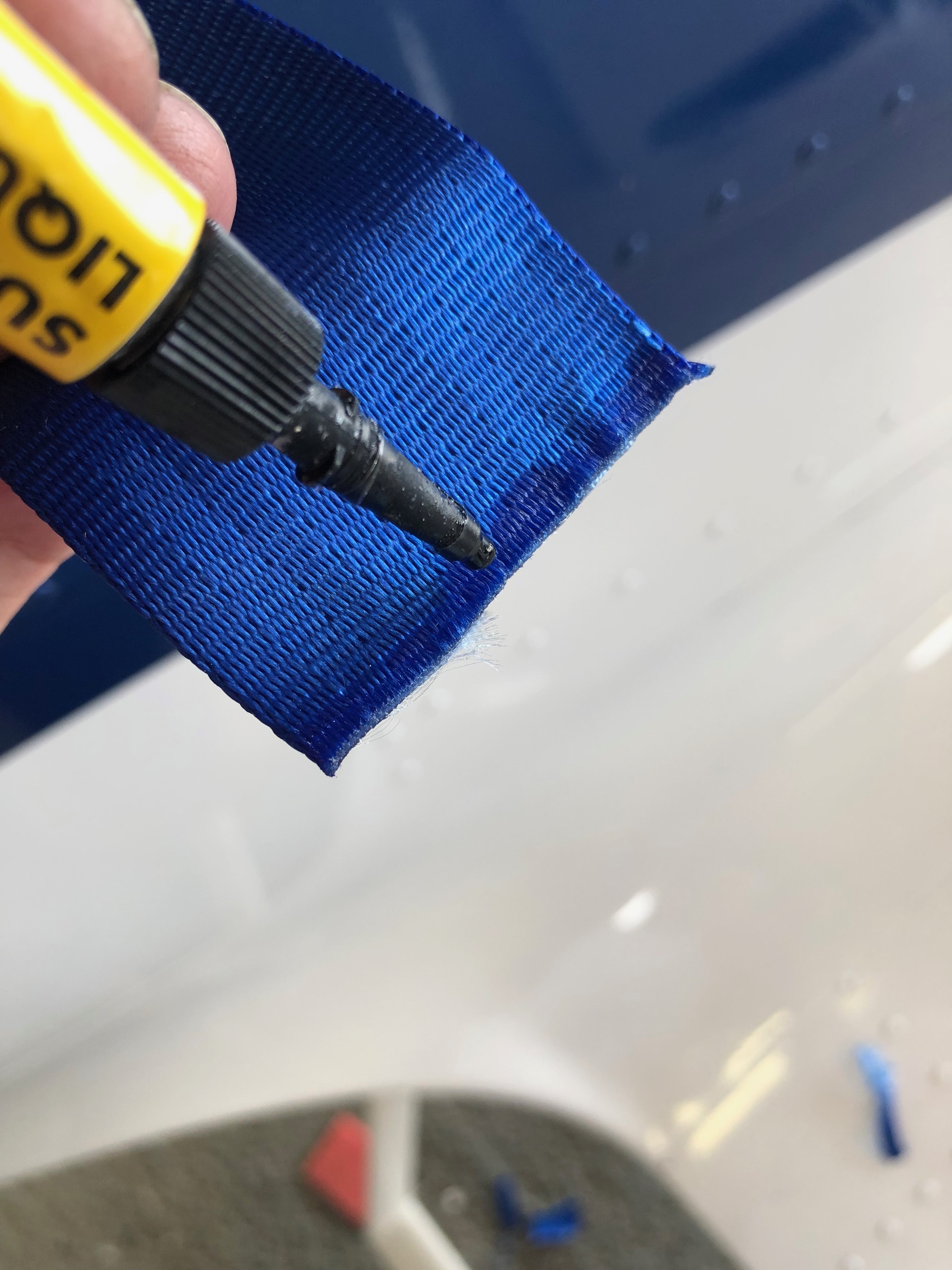
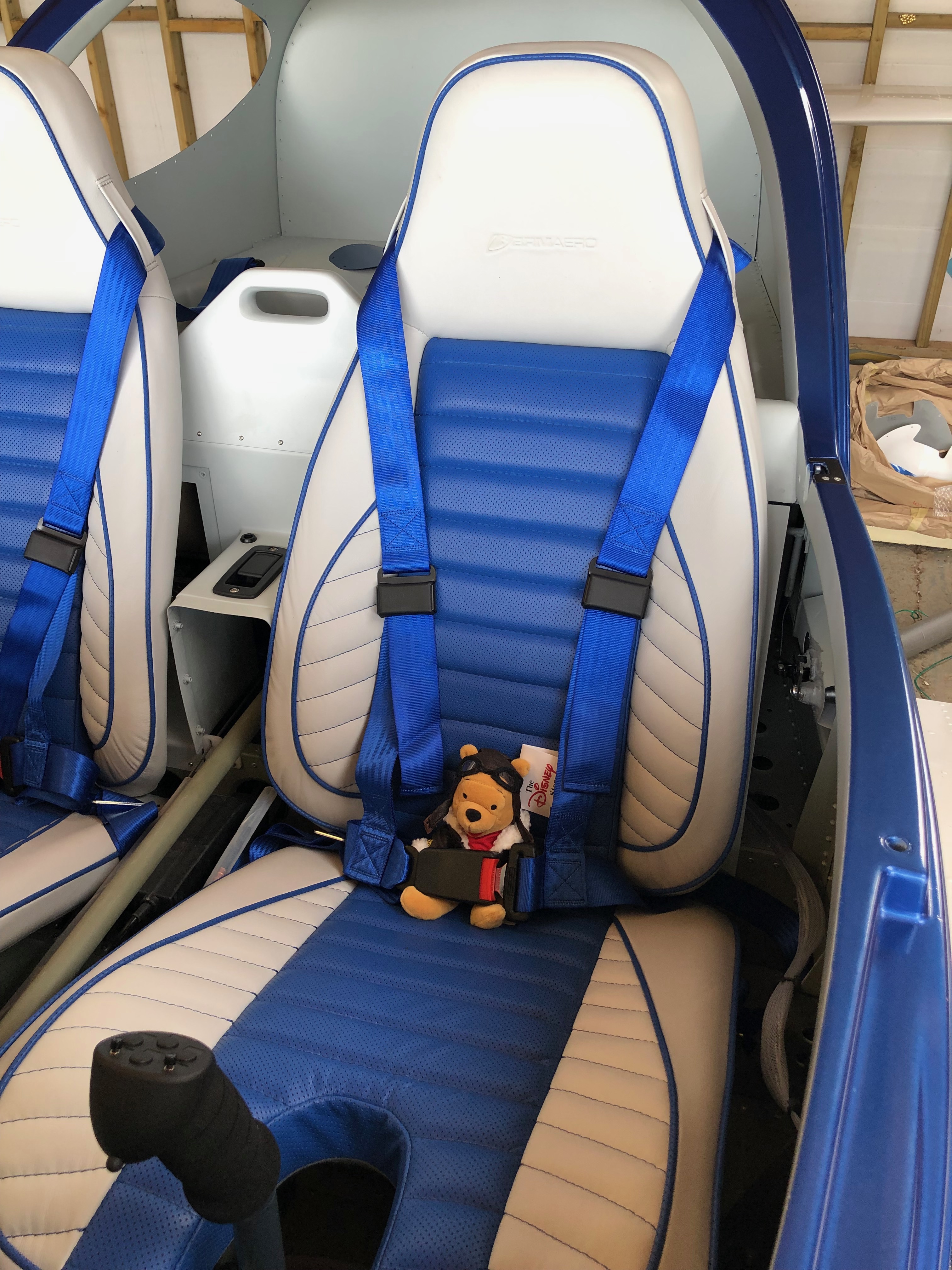
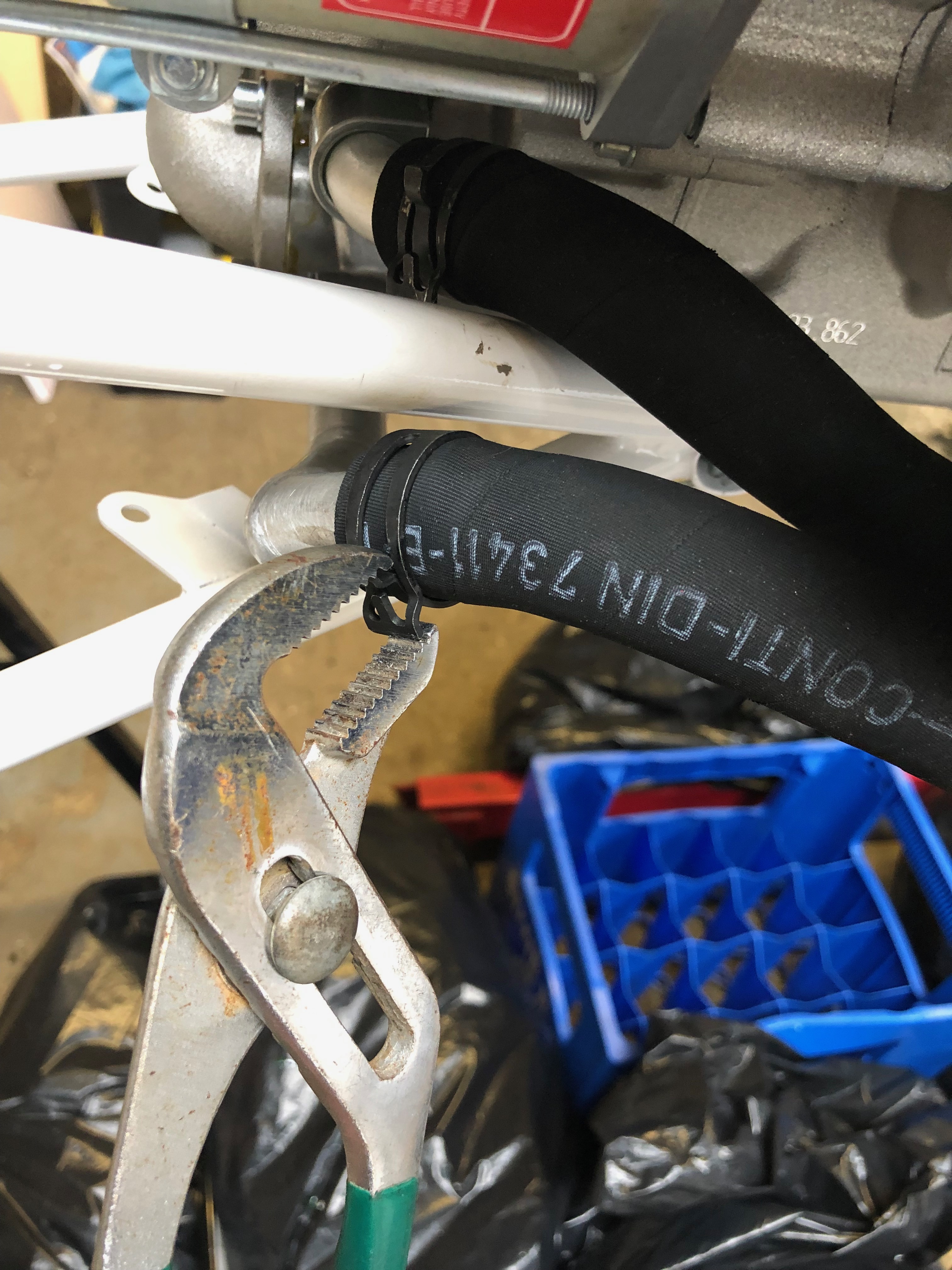
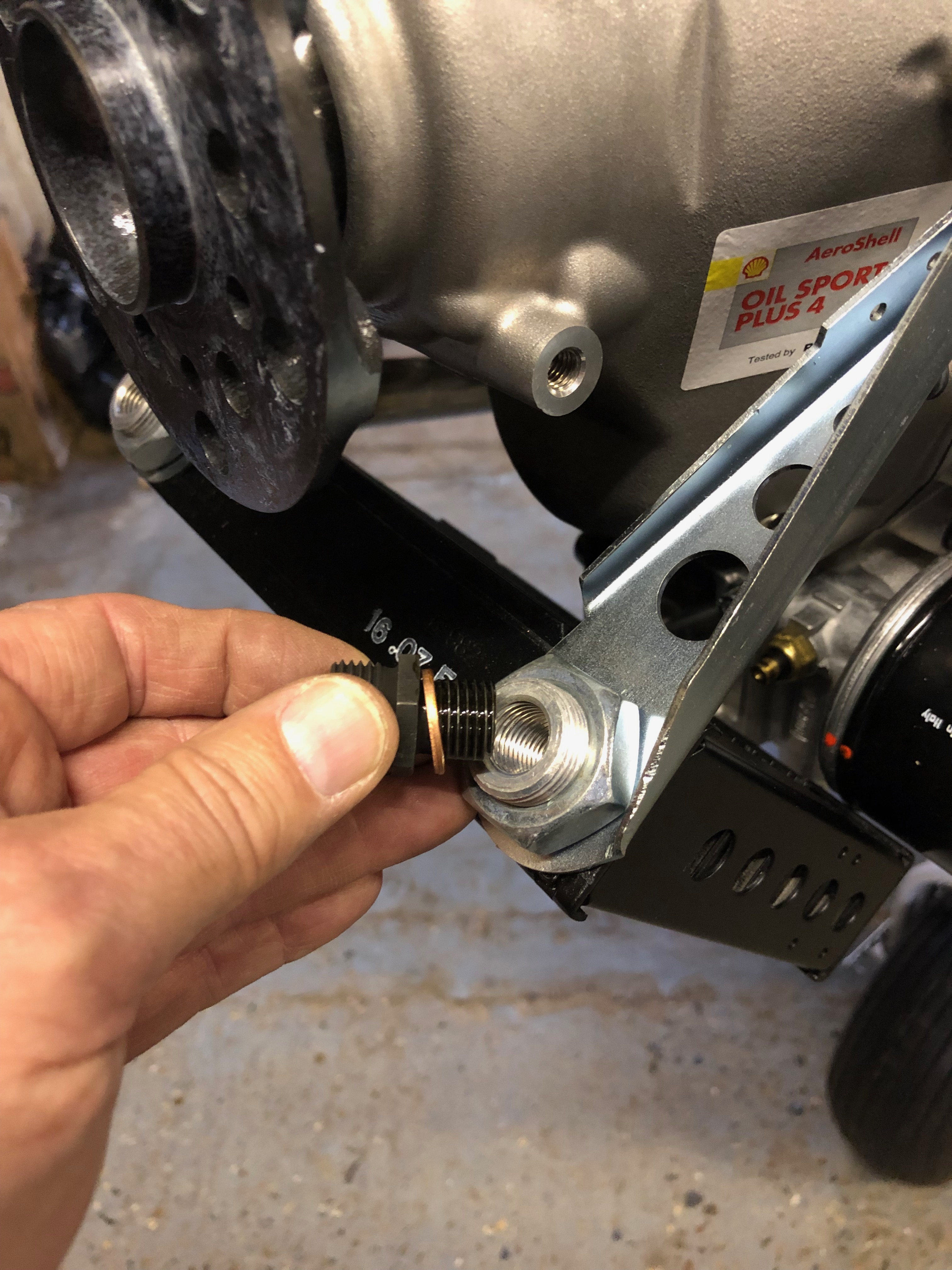
The order that I’ve been waiting for was an 18mm x 1 fine pitch die to cut a little more thread on each water pump pipe. Fairly easy to do but I make to make sure that the die went on perfectly straight otherwise it might start cutting a new thread!All done and sealed with Loctite. I’m going to leave it in position for a couple of days to fully cure before touching the pipes. Hopefully this will ensure I won’t have a repeat of the leak.Now onto the floats. I spoke to CFS aero who are the importers for Rotax engines and they sent me a full set of new floats to replace those that were in my carbs. This is really a precautionary measure as I don’t know if the floats fitted are defective or not but I didn’t want to find out on the first flight! To get to the float chambers I have to undo some of the work that I’ve done previously. First off are the carb drip trays……revealing the float bowl retaining clip. This is prised off to allow the bowl to be removed.The flaots sit in the bowl and rise and fall on pins to retain them. Brings back memories when I used to play about with motorcycles when I was younger.When refitting must make sure that I don’t damage this mechanism and ensure that the seal is seated correctly.Then a refit of the carb drip trays before repeating the procedure on the other carb.All done and back to home it was before my intervention.Next on the agenda is to fit the seatbelts. Three bolts and nyloc nuts are used to secure them.The top hole in the retaining mount is opened up to 11mm before the bolts can be fitted.The top retaining strap is fitted first and tightened to pinch the fitting and then just eased off slightly to allow for some movement in operation.The bolts with a ‘shoulder’ are then fitted to to the left and right seatbelt retaining brackets.The top strap is too long to use as is so the seatbelt webbing needs to be modified by cutting and running through the retaining adjusters.To stop the webbing flying in service I’ve sealed the ends with superglue. This may work ok but if it fails after some use I’ll seal with heat instead but this seemed a good solution.With both side now done is was time to try out on a ‘real’ pilot so Pilot Pooh was given first go…
A short day today as I was hoping that the M18 x 1 die would be delivered today so I could do the work in the afternoon. Unfortunately for some reason it was delayed so will have to wait in for it tomorrow now. The leak has caused me a couple of days delay so far which is a little frustrating.
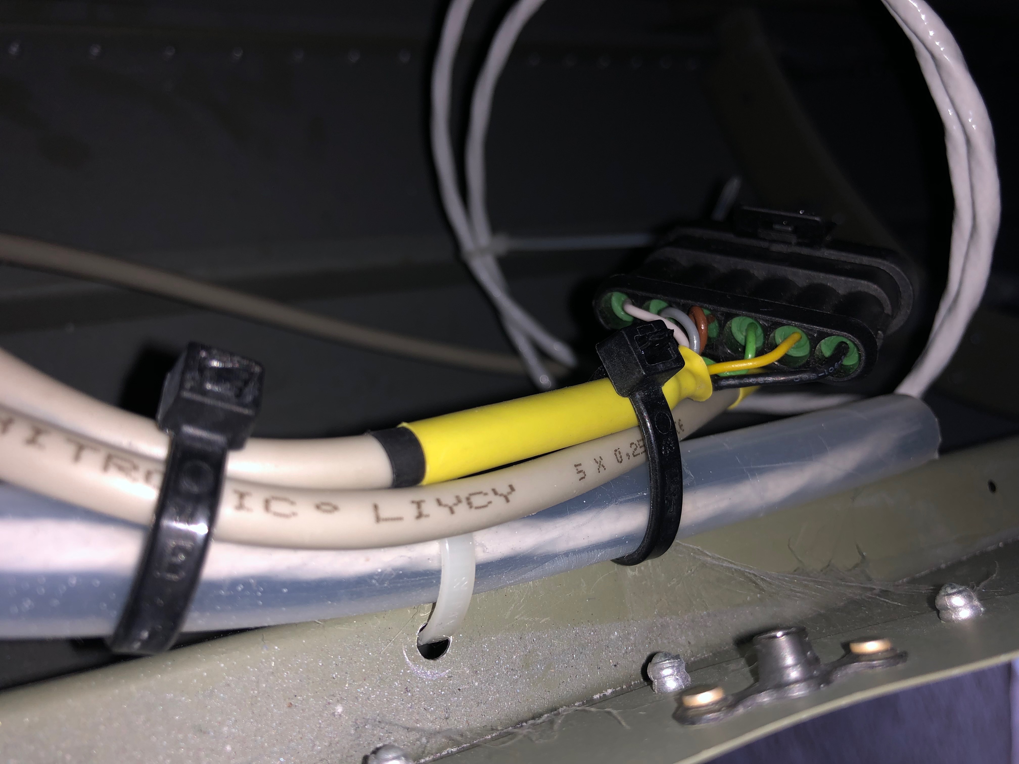
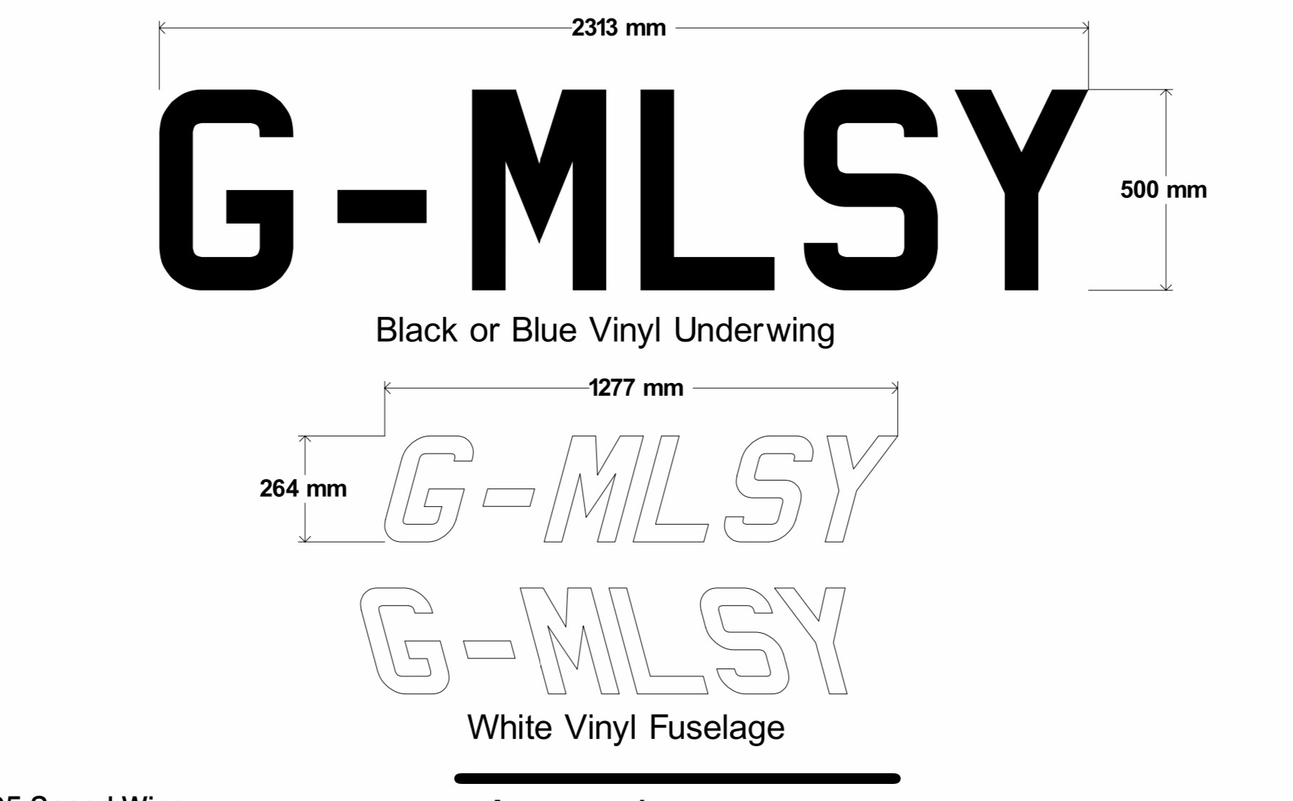
With the water pump dismantled I need to use a M18 x 1 die to cut further down the pipe to provide a better seal than achieved on the first fit. This is a revised method that has worked for others that have had this problem according to Bristell.The wires connecting the lights, strobes, trim motor and pitot in the wings need to be protected so a piece of flexible conduit is used.The elevator trim and lights connectors are secured to prevent them from moving in service.The artwork for the registration has been prepared and I’m obtaining a couple of quotes before ordering.
Music: Karen was in charge of music so played tracks like ‘I can fix you’ and ‘All right now’ Very funny Karen!
As I was packing up last night I noticed a wet patch under the front tyre. When I investigated I found a very small leak from two of the modified water pump pipes. Unfortunately there was no way round it, the pump will have to be removed, the pipes removed and resealed. A call to Tony Palmer revealed that there had been other cases of leaking and was put down to a loose fitting pipe. The solution is to cut the thread slightly further down the pipe so it’s a tight fit when at the correct angle. Karen came along to give me a hand.
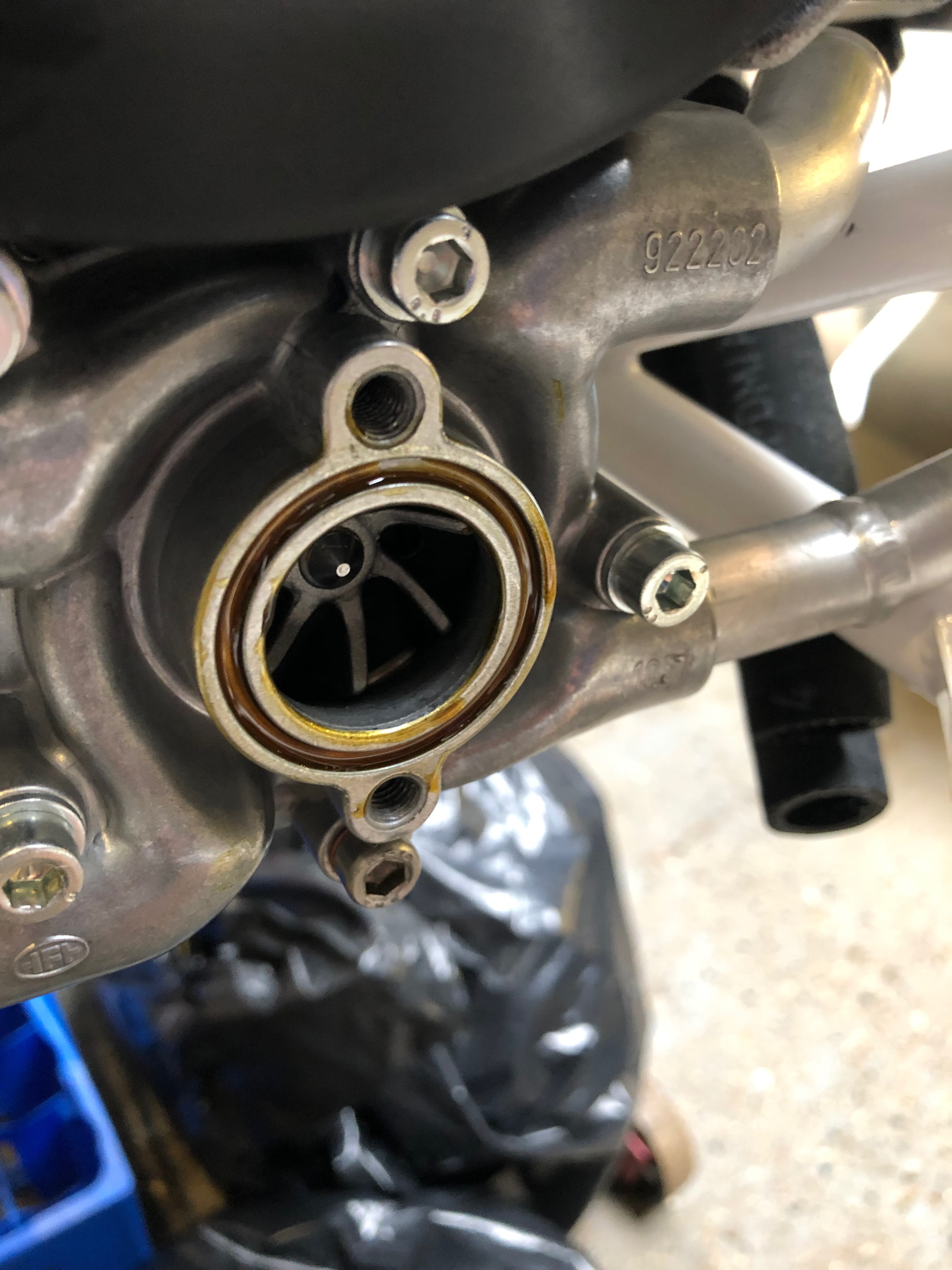
The slight leak. Can’t ignore it, if it leaks with no pressure in the system it’ll certainly leak a lot more when the engine is running.So the coolant needs to be drained……so I can remove the pump. I’ve removed the pipes from the water pump, cleaned the thread but now have to order an 18mm die. I’ll use the die to cut a slightly longer thread.As I can’t do anymore on the water pump I though i’d Loctite the12 set screws, 4 on each blade and…… add some Torque Seal on the set screws to allow any movement to be identified. I know have to wait for the Die to come before I can finish off the water pump.
Today’s tasks included finalising the oil tank pipe run, prototyping the water radiator return hose, installing the fuel pressure sensor Tee and the ‘stand-offs’ to ensure adjacent pipes don’t rub against each other.
The water return hose requires a 22mm elbow to enable it to fit the installation. I’ve used an ordinary copper solder ring plumbing elbow. The solder ring gives a raised ring that allows the clamp to hold the fitting securely.
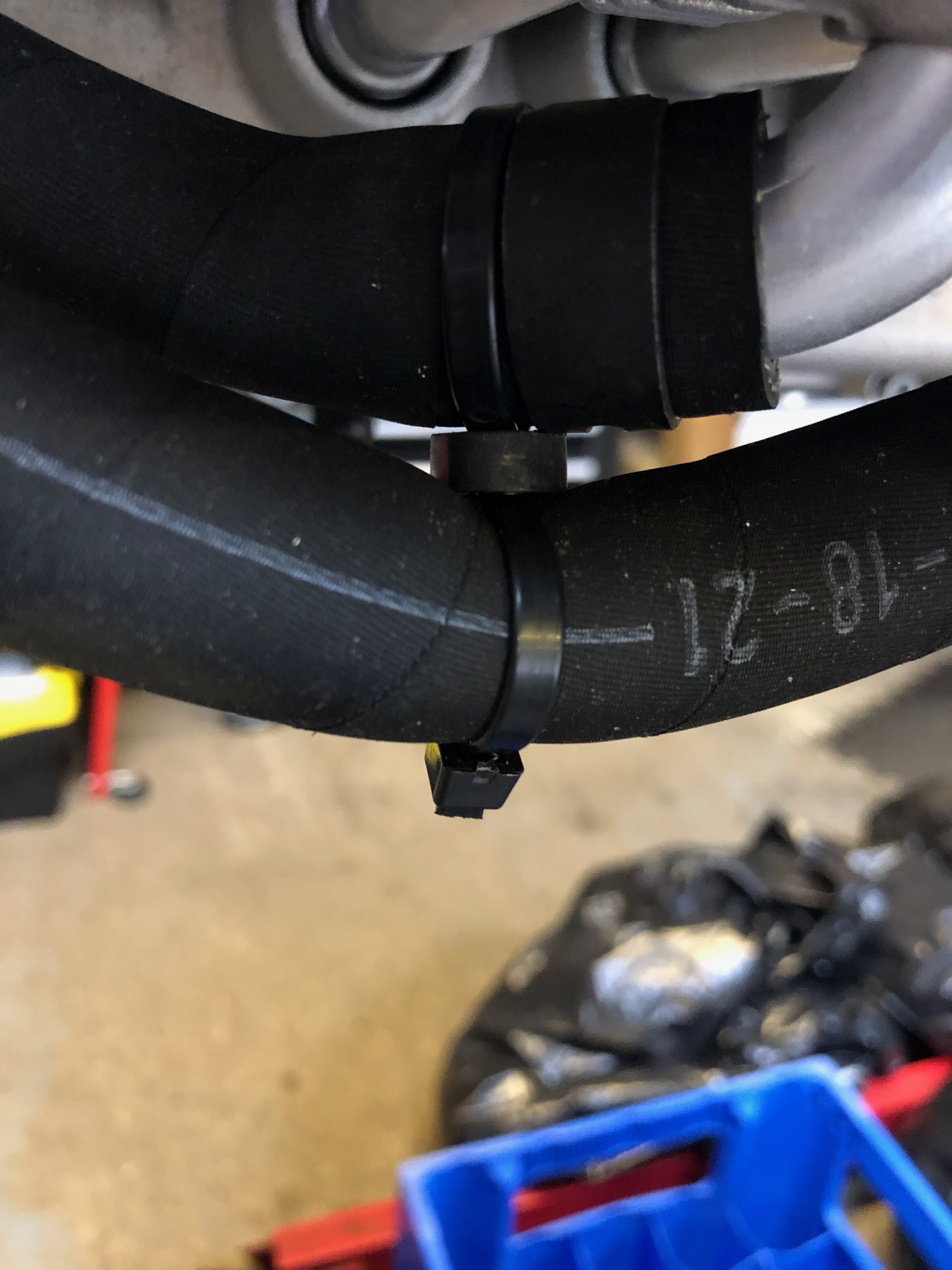
After running the hoses most need stand offs to make sure they don’t rub on adjacent pipes
A view from the top showing the fuel pressure switch just behind the gearbox and the top oil hose on the left.
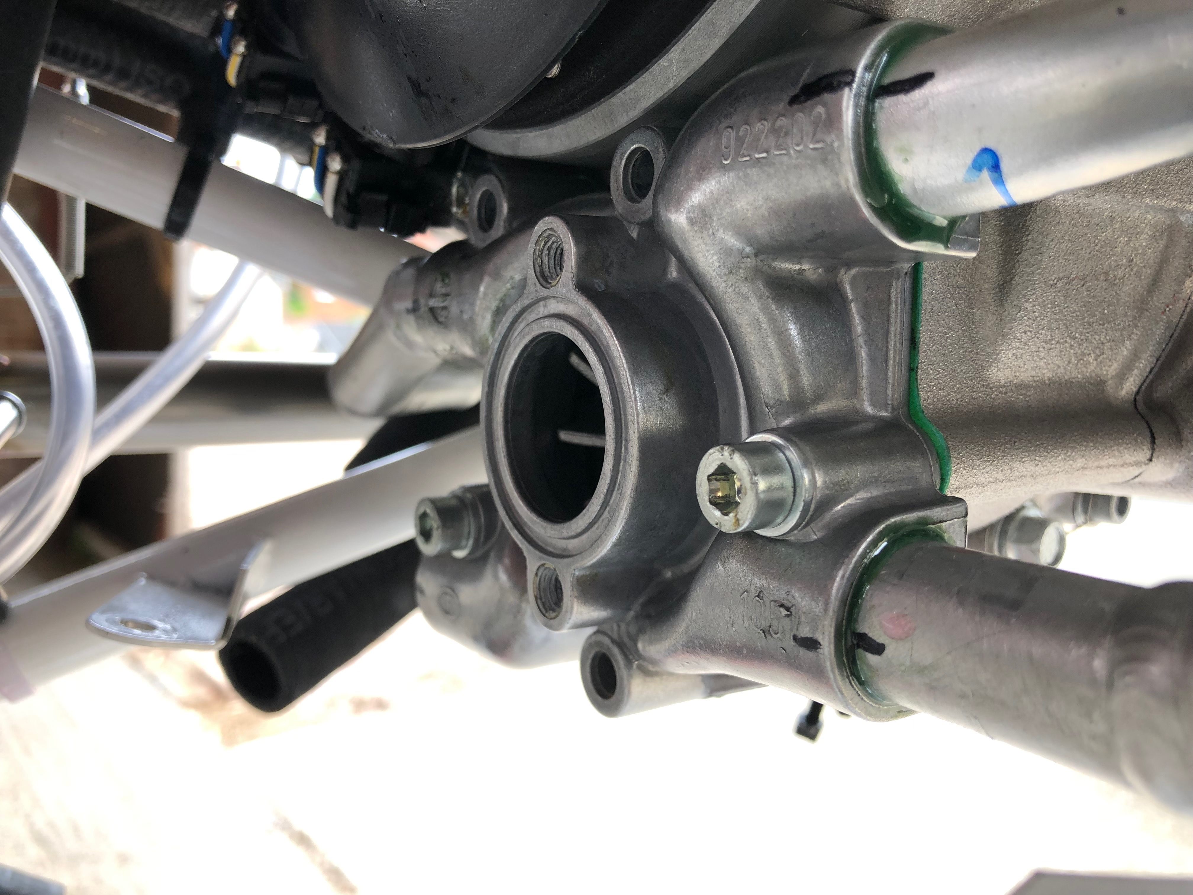
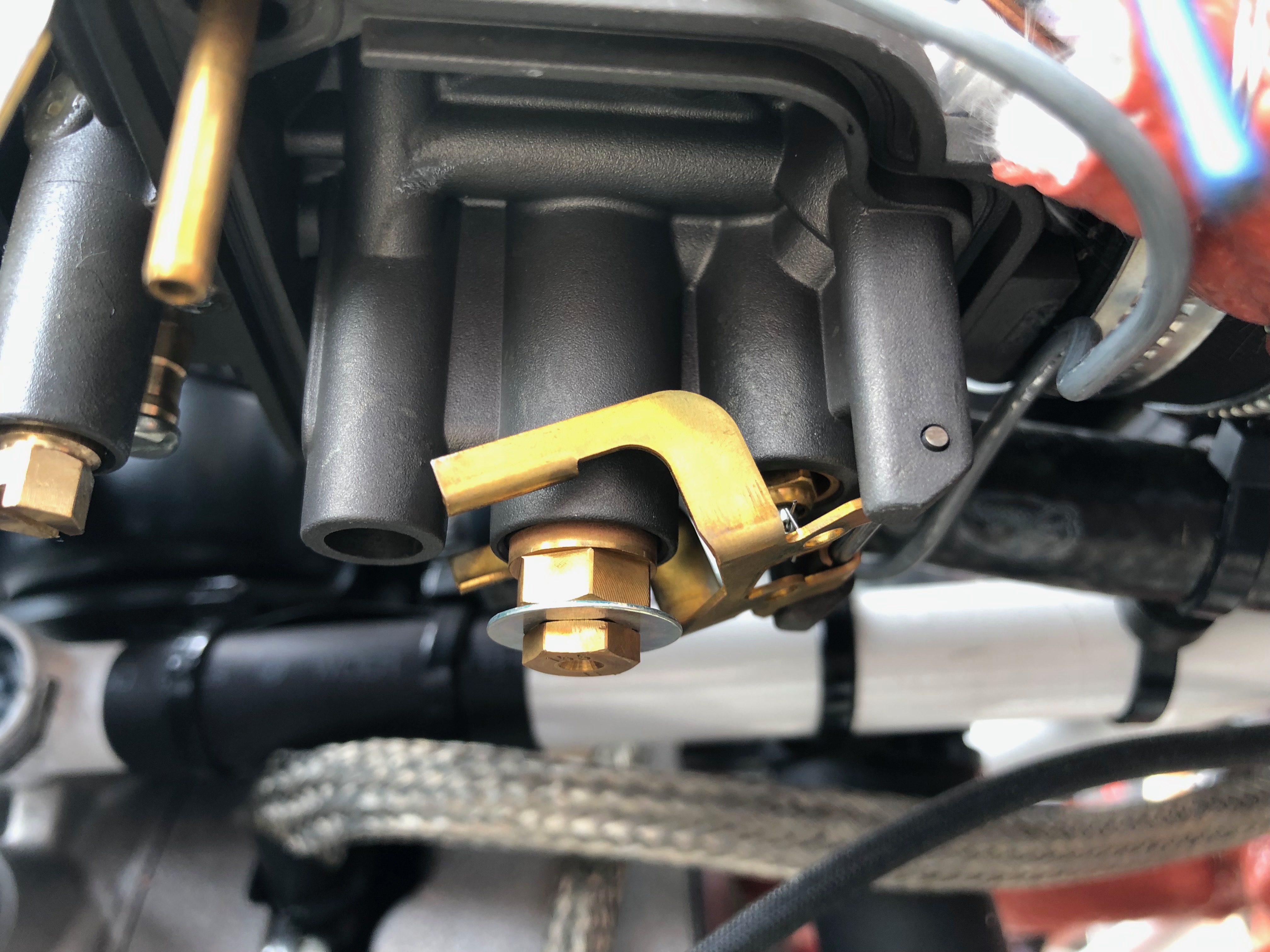
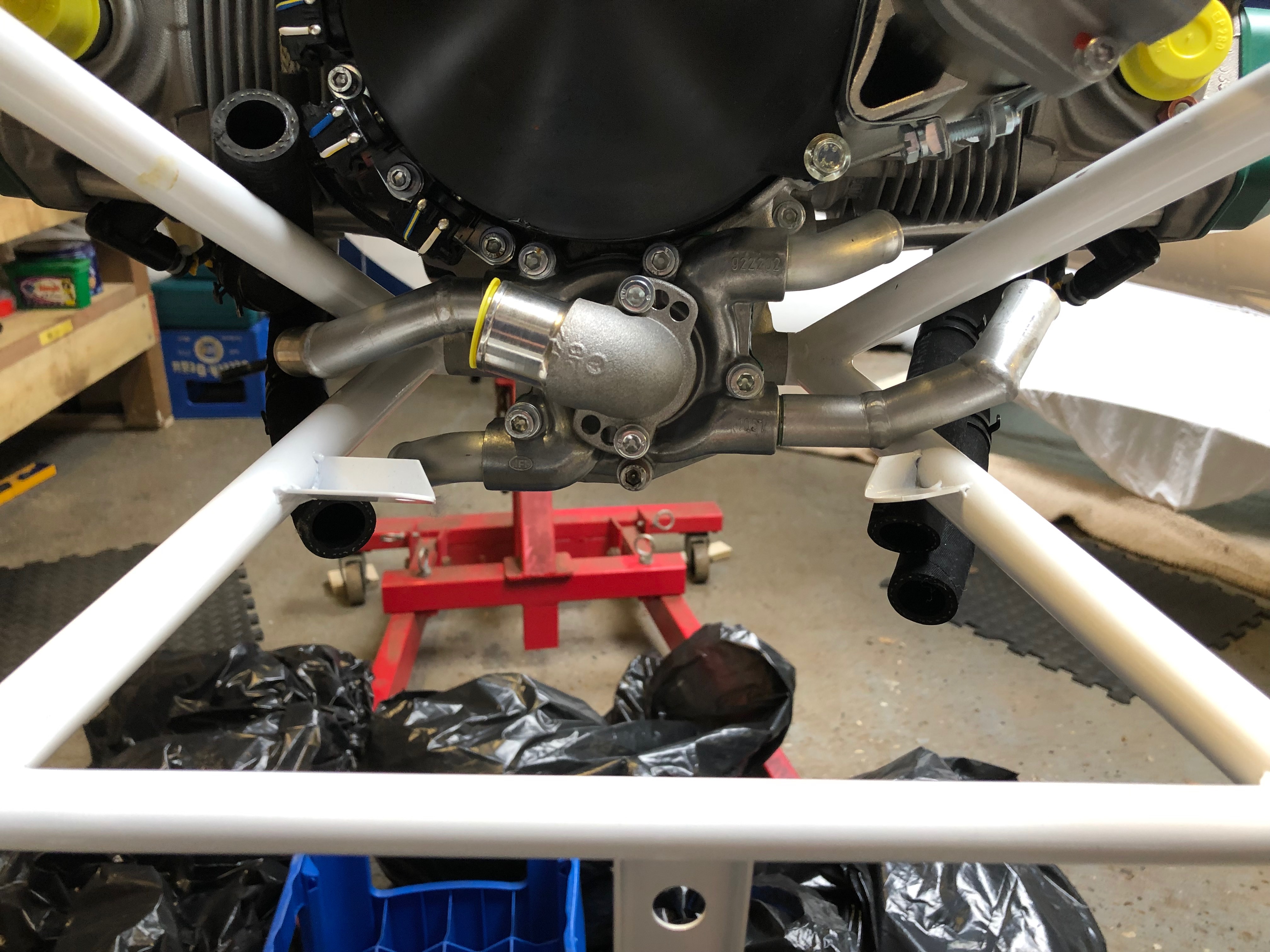
Now the Loctite is set the water pump pipes can be refitted.
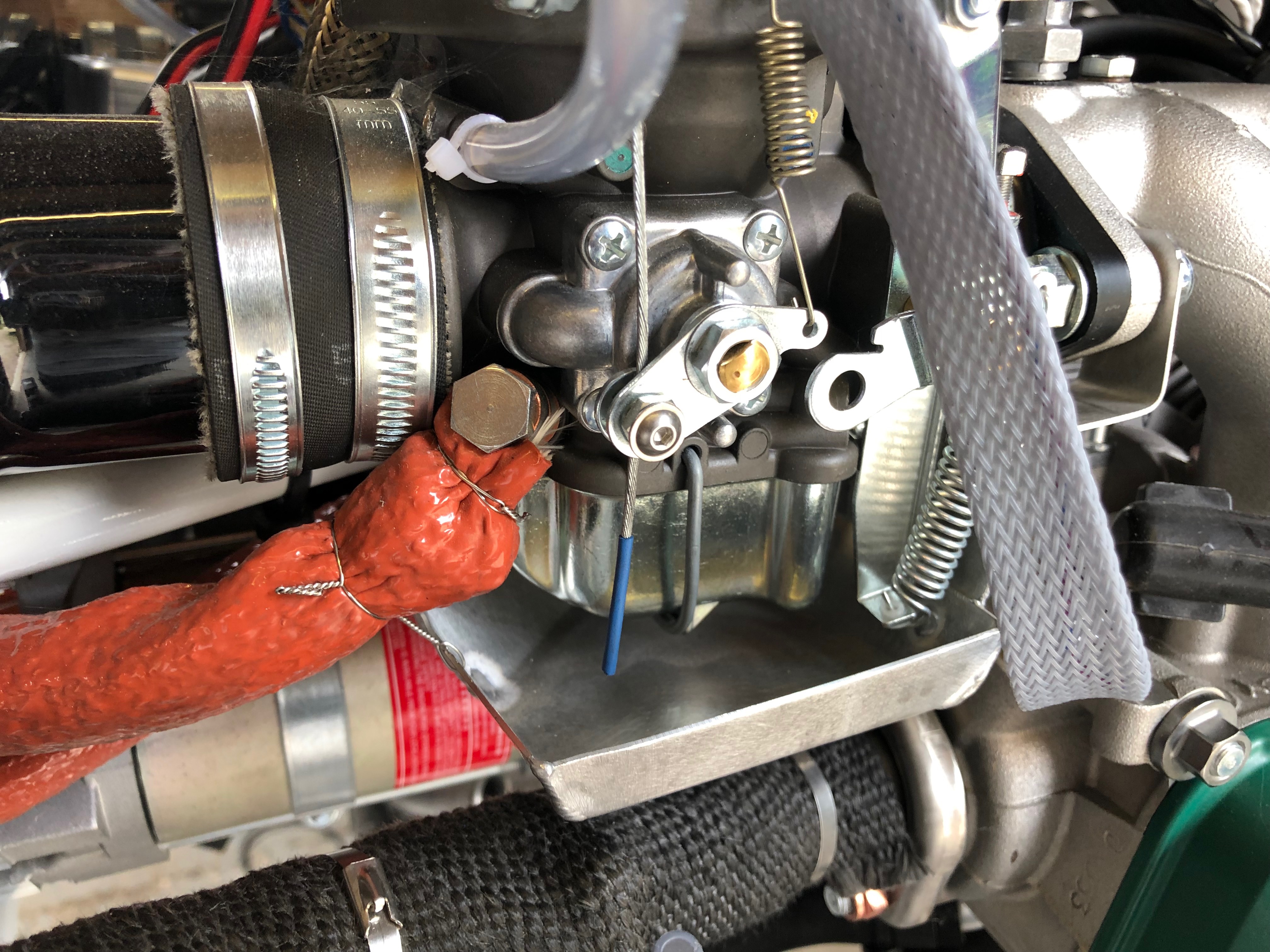
A ‘stand off’ is required to stop these 2 pipes from rubbing.
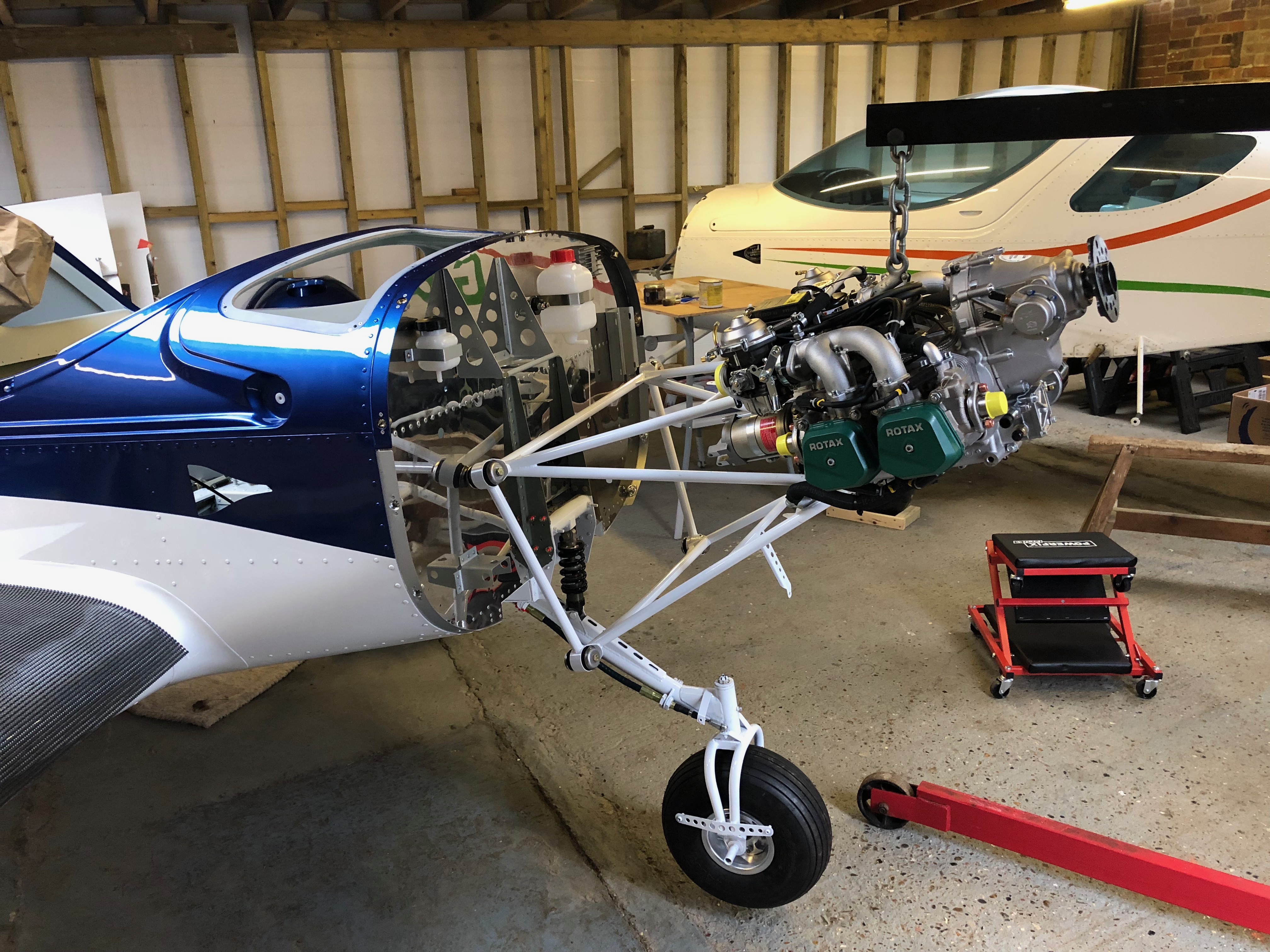
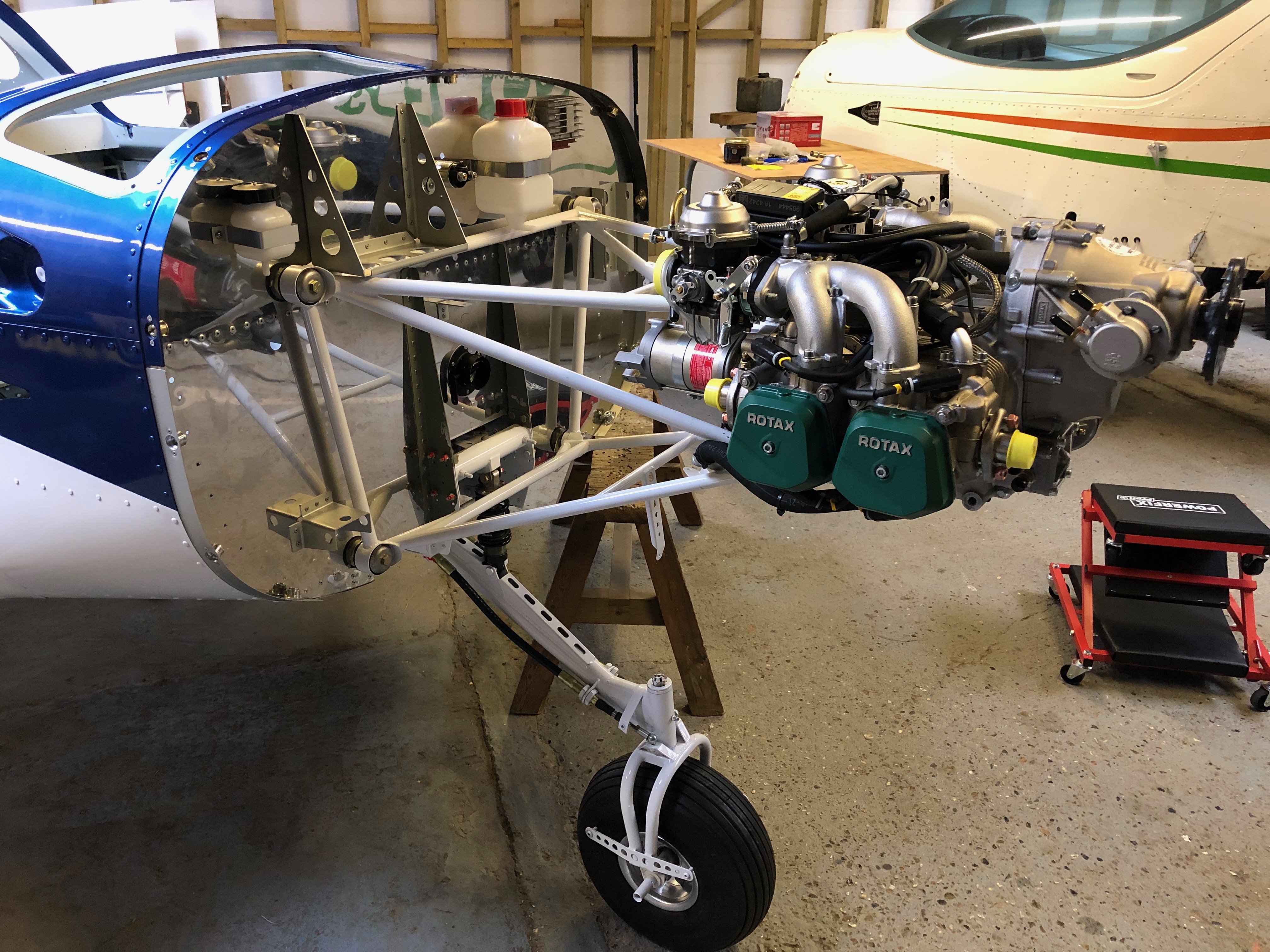
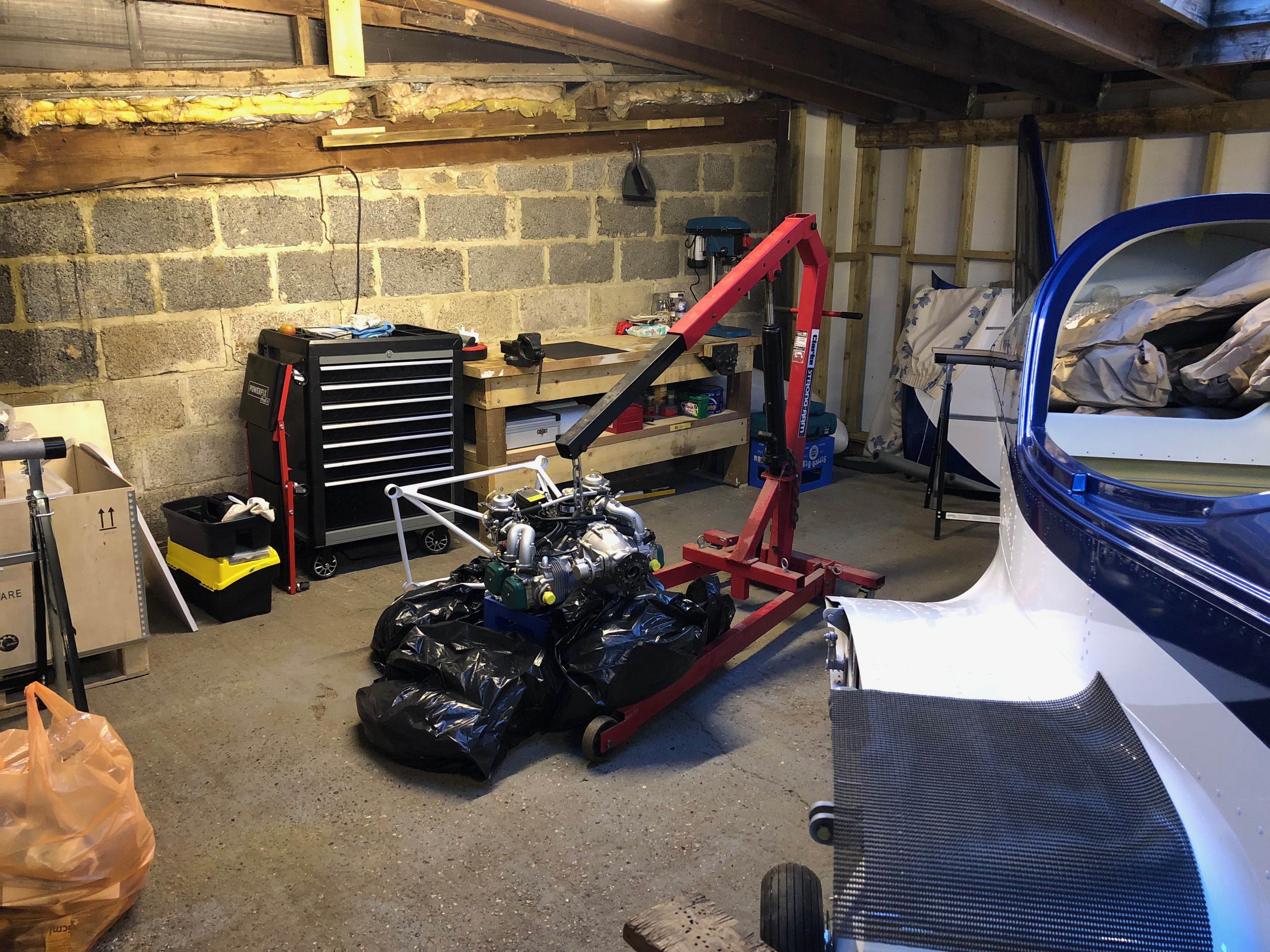
Time to hang the engine. The engine hoist and engine is positioned just in front of the fuselage and hoisted to roughly the correct height.
The engine mount steel cup washers are covered in jointing compound to stop them rusting once fitted.
First of 4 bolts to be fitted. 3 were quite easy to fit with the forth taking about 10 minutes to position properly as the rubber mount had turned slightly.
With the engine mounted and bolts tightened it’s time to fit the exhaust system.
The bespoke Bristell exhaust downpipes are fitted first.
The exhaust box is hung using springs and flexible couplings to provide a leak free system.
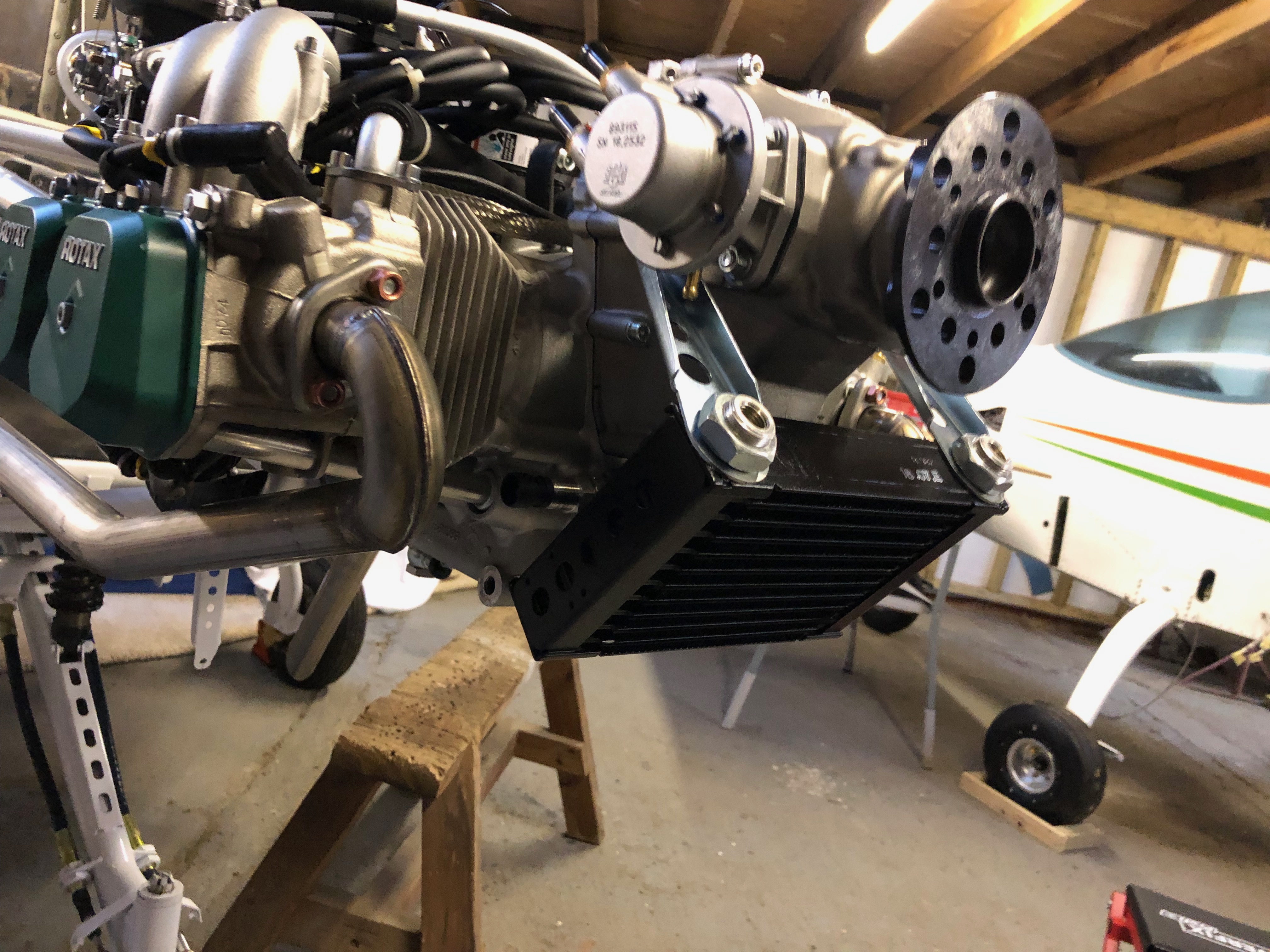
Next the oil cooler is fitted using the brackets provided.
and adapters are fitted to accept the aluminium connector pipes.
Good progress for the day. A tidy up of the workshop in readiness for tomorrow.
Now the Loctite has set the pump can be rebuilt, The mating faces and gasket were degreased and Wellseal applied, left to set before being reassembled.
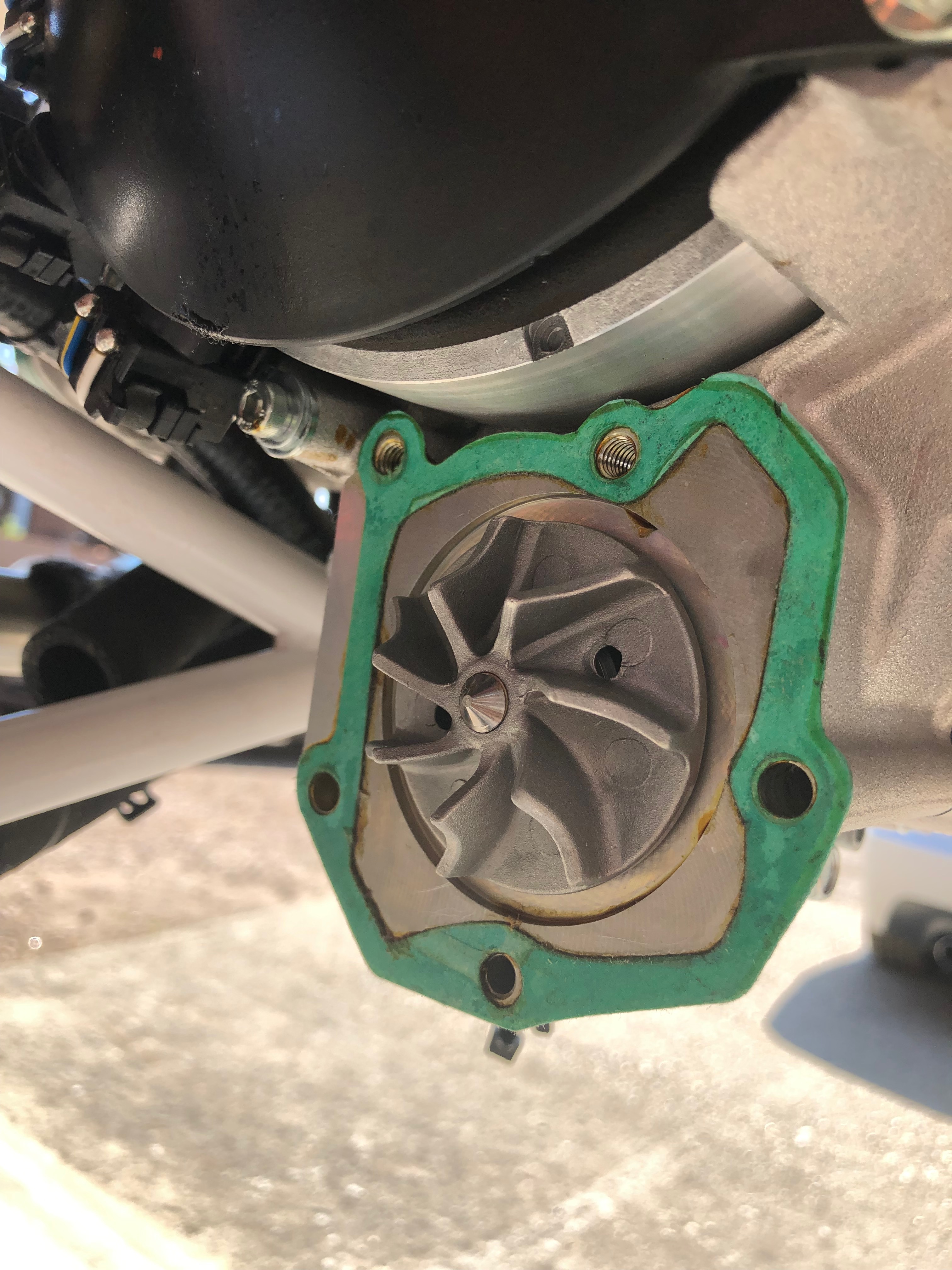
The impeller cover seal is also refitted after a bead of Wellseal is applied. All bolts were then tightened to the correct torque.
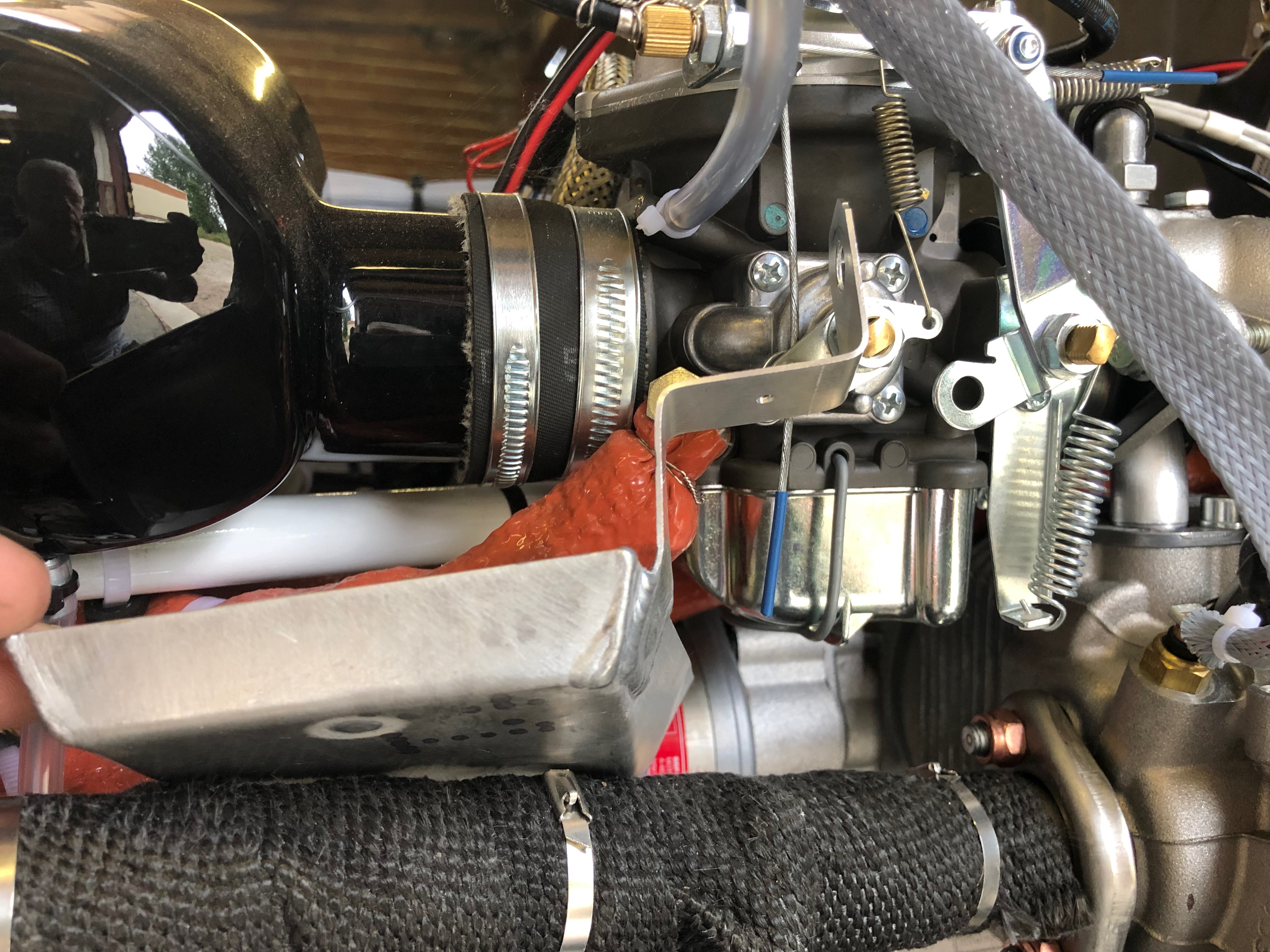
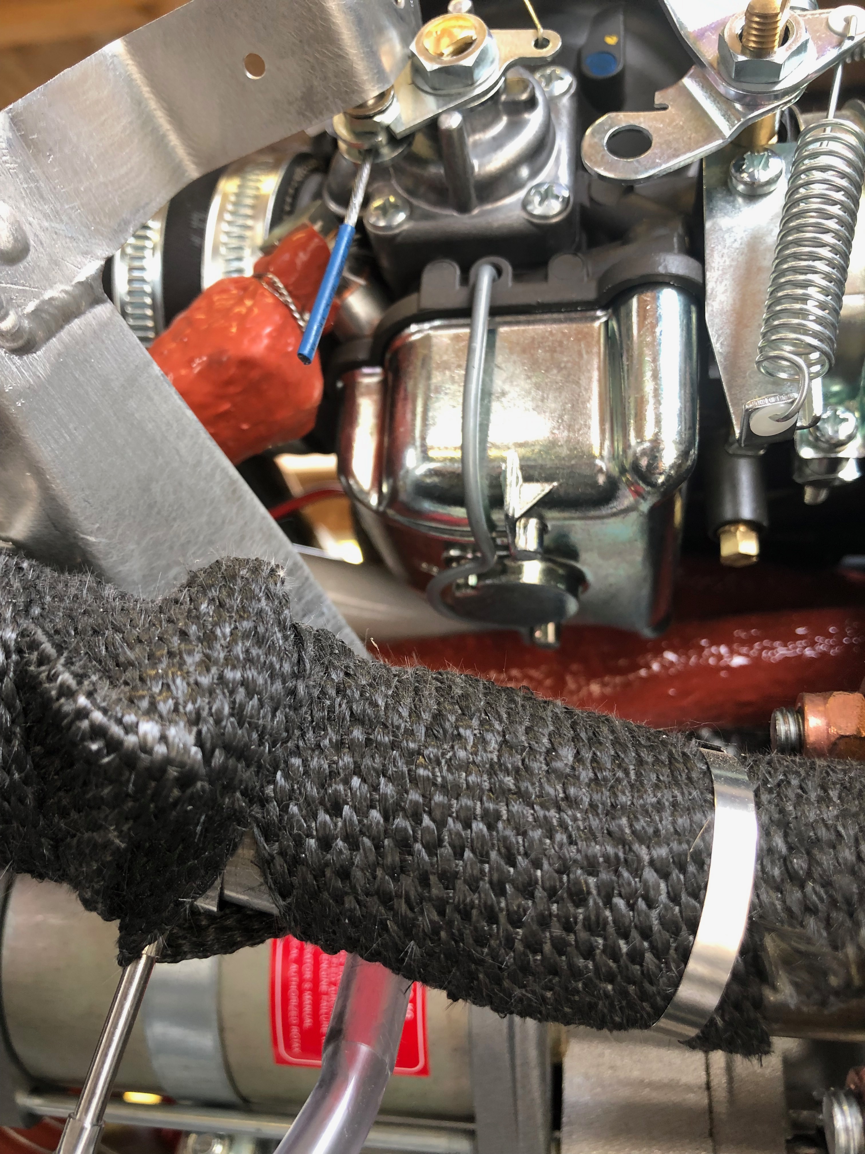
The water pump refitted clearly showing the new position of the modified pipes around the Bristell engine mount. The rubber pipes will be refitted tomorrow allowing the Loctite to further harden.
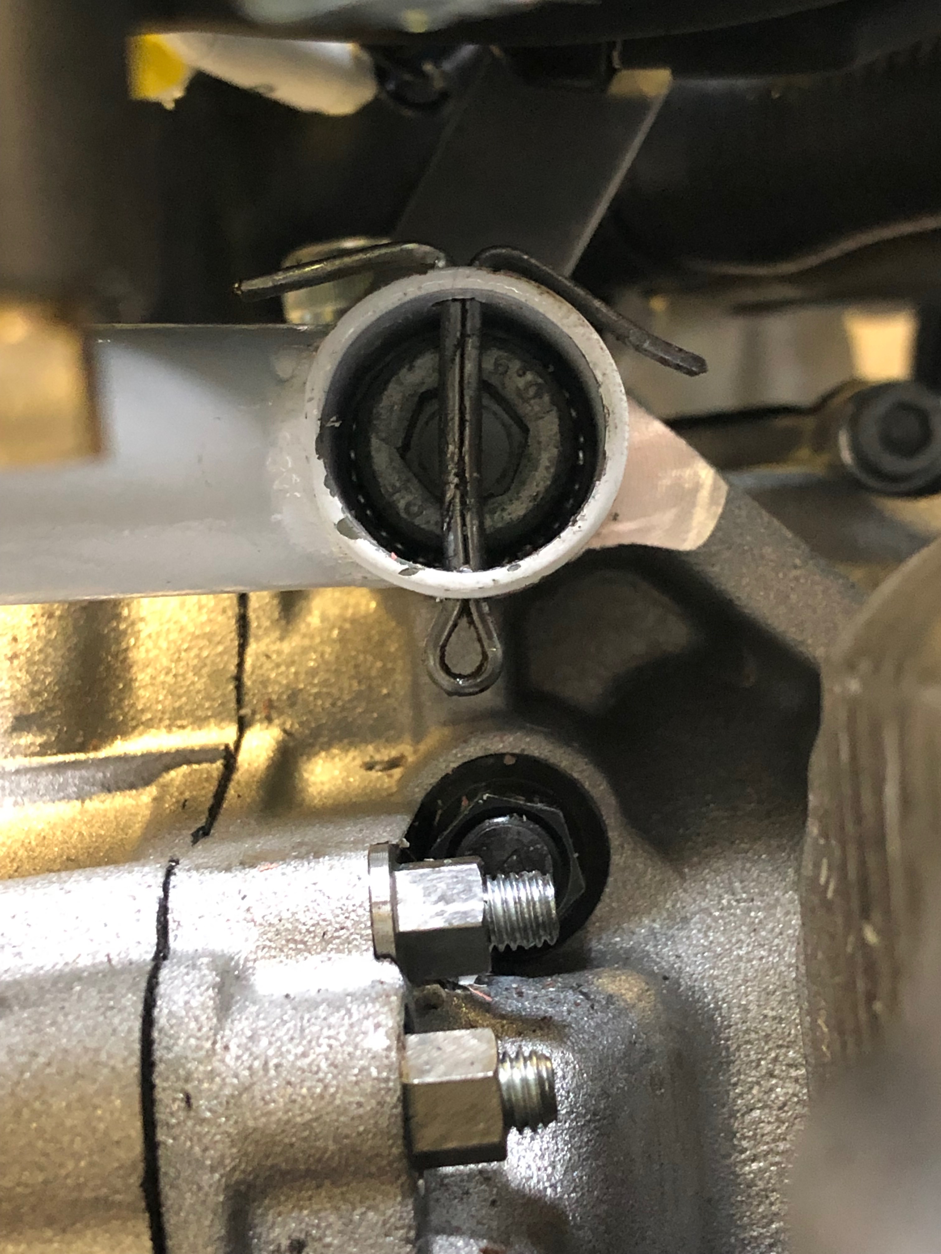
Split pins are inserted through the engine mount to retain the engine bolts should they loosen ensuring that they won’t fall out when in service.
Three of the split pins are easy to install but top right is impossible without taking the control unit off so this one was installed upside down but still does the job of retaining the bolt should it work loose.
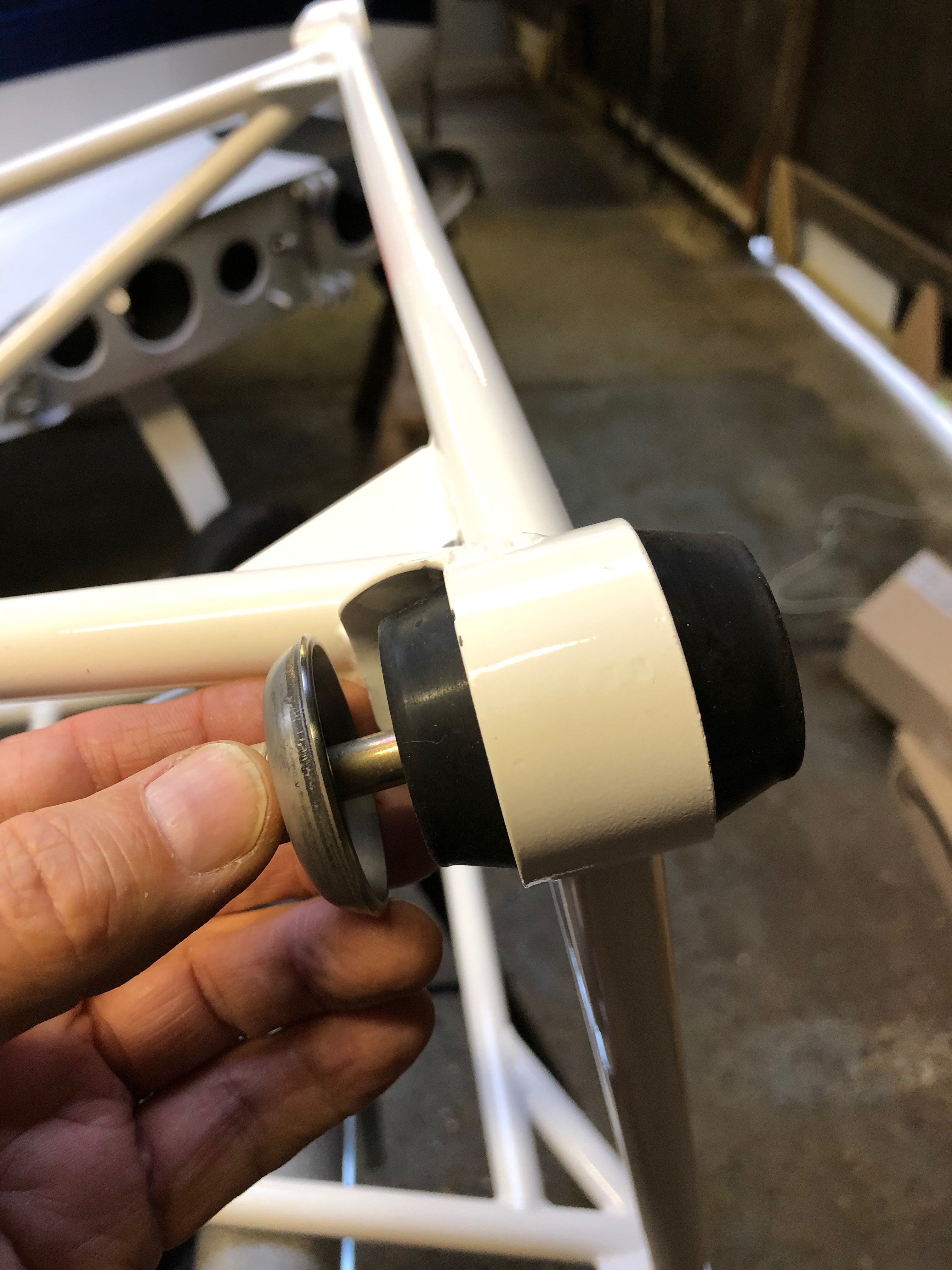
I test fitted the engine vibration bushes onto the engine mount in preparation for hanging the engine tomorrow.
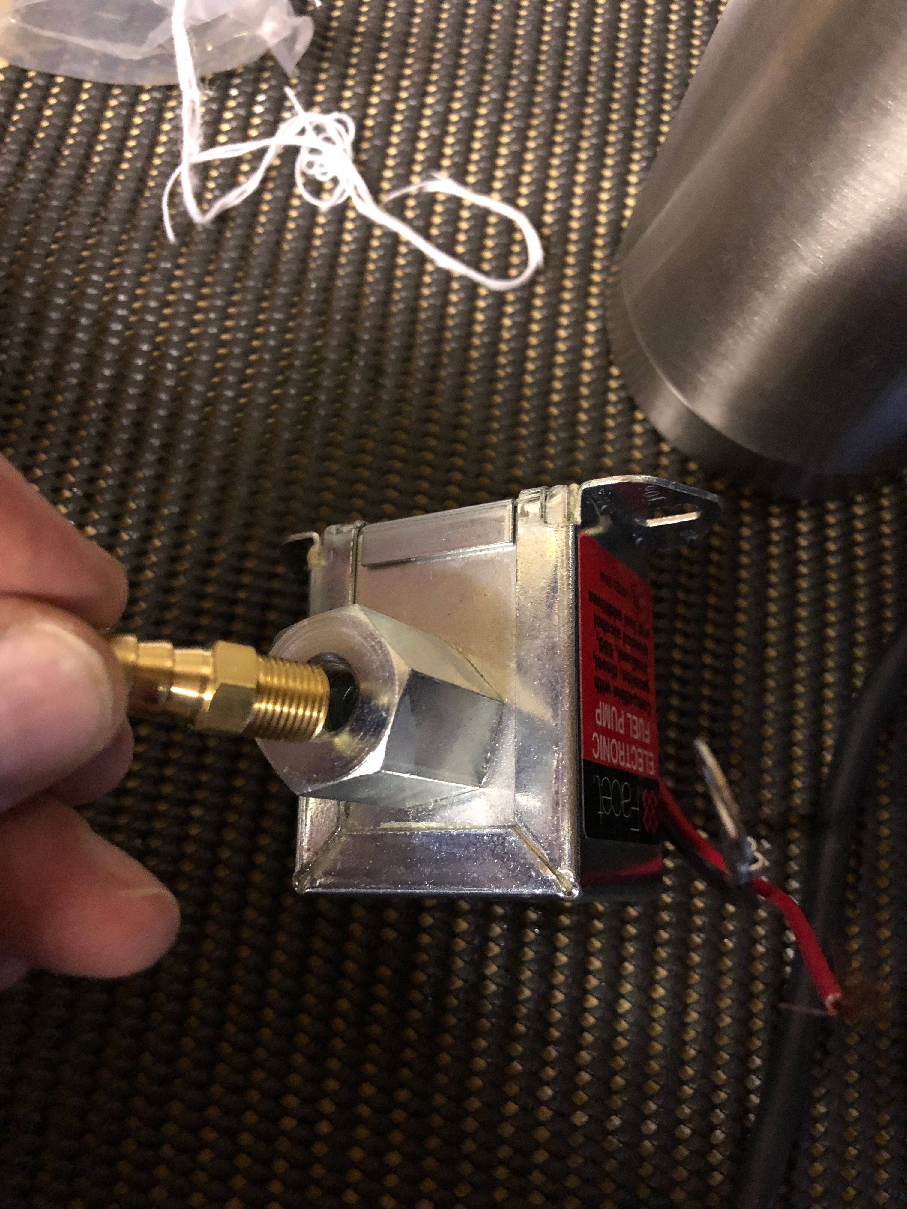
One of the miscellaneous tasks that needs to be done. The electric fuel pump fittings are screwed in after applying Wellseal around the thread ensuring the ‘water tight’ seal.
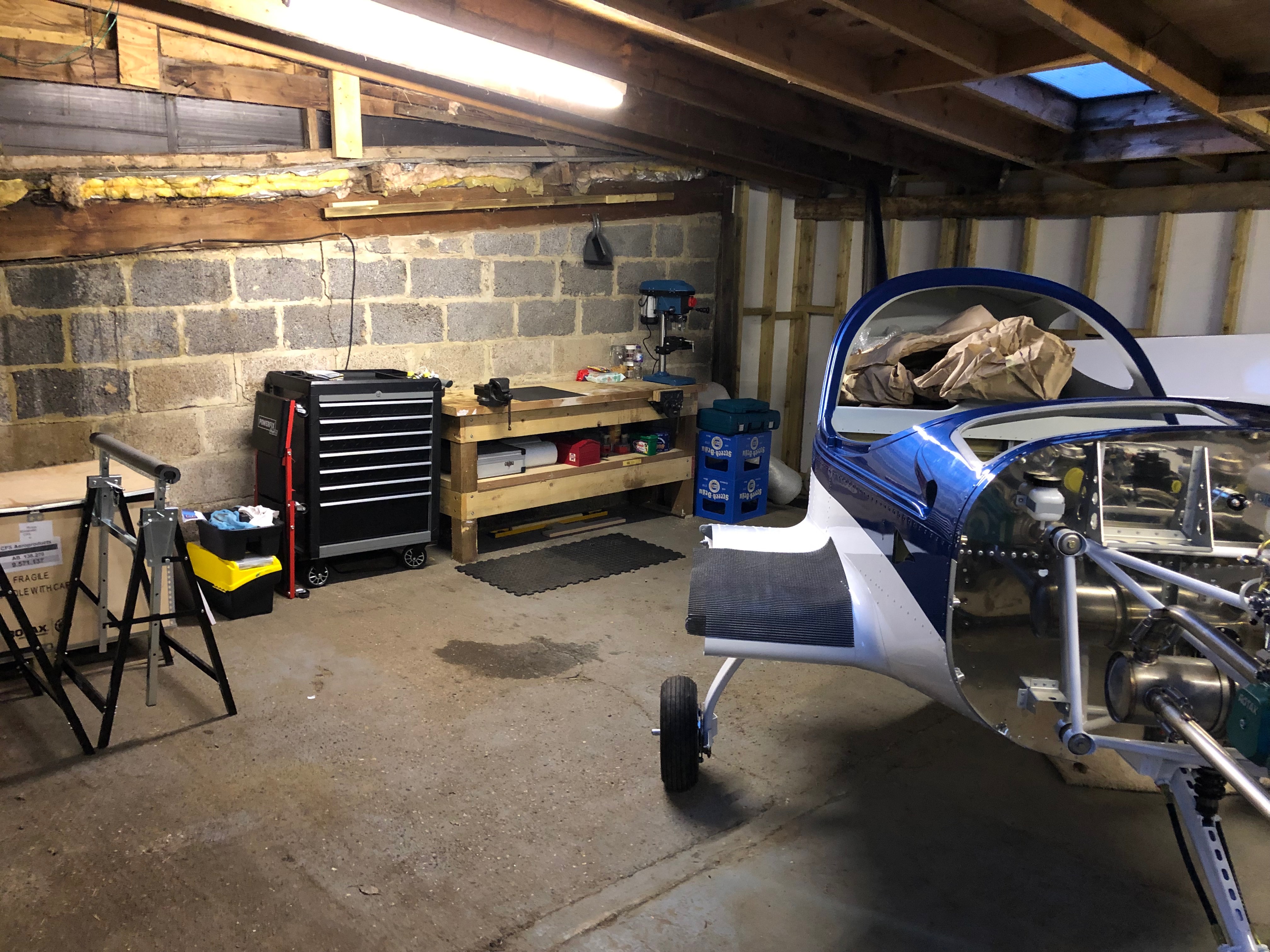
The usual resting place overnight. Hopefully the last time I’ll have to do this!
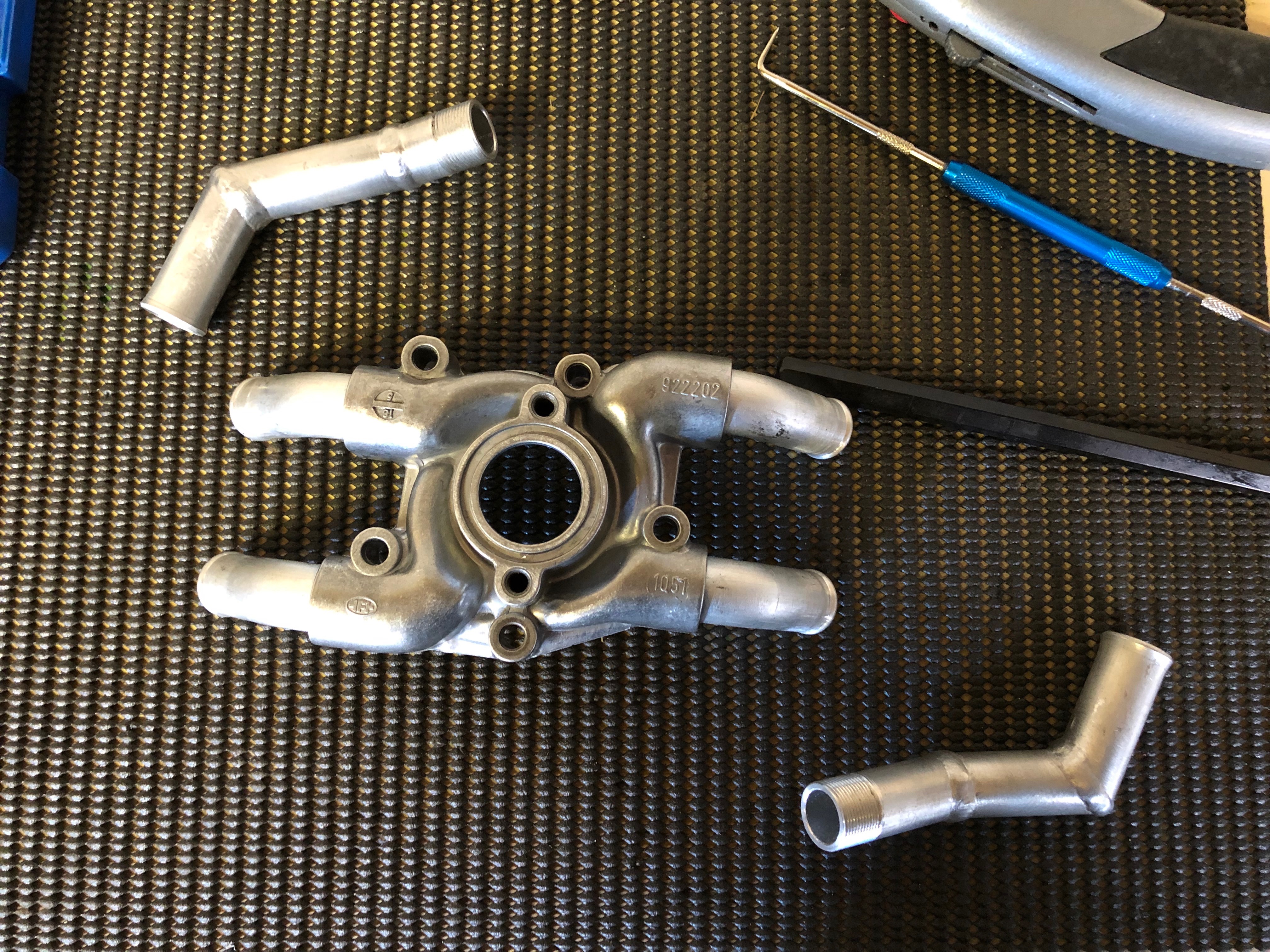
Time to modify the pump. The top left and bottom right pipes will be changed and the other two will be removed and refitted at a different angle to suit the Bristell engine mount.
The pump and pipes are heated until the existing Loctite bubbles and then a long bar is used to unscrew the pipe. This is repeated for all four pipes.
The old Loctite is removed by using a scribe and some thinners ready for reuse.
As the new pipes are manufactured by cutting and welding the insides should be checked for weld debris and cleaned.
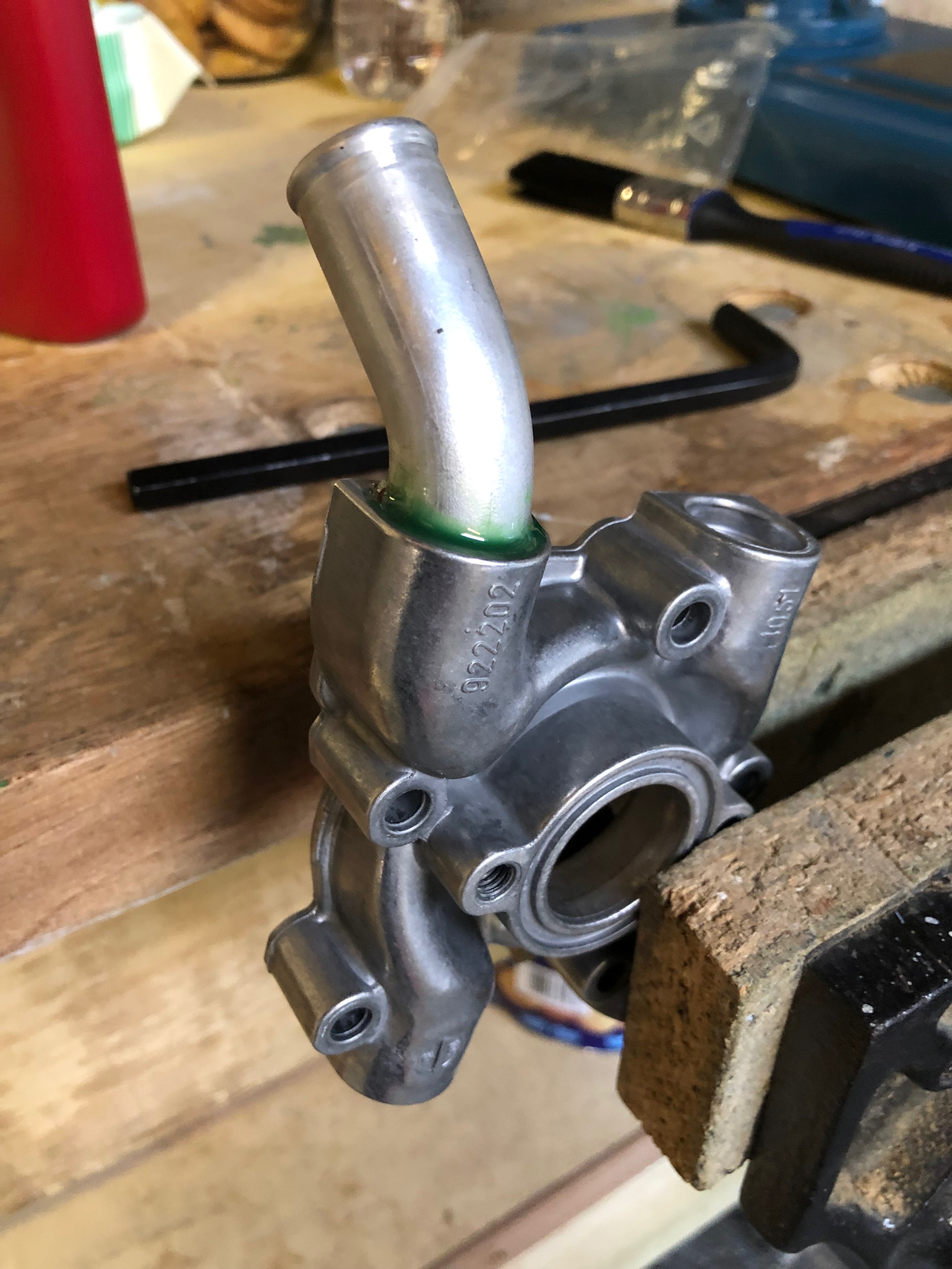
Loctite 620 is applied to the thread and the first of four pipes are refitted. The pump is offered up to the engine and the angle of the pipe is checked to ensure that it doesn’t foul the engine mount and that there is enough clearance to refit the water pump pipe .
All the pipes fitted and angled correctly and left to set overnight.
Again the engine is lowered overnight for peace of mind.
Following the build of my Bristell NG5 Kit No. 382 Registration G-MLSY