There’s still a few jobs to do before final sign off hopefully next week. I’ve moved G-MLSY out of the workshop but I’m still using it for my tools. It’s now housed in one of the mid sized hangers until I finish when it’ll be moved to the main hanger.
After the success of the first engine run on Friday I need to adjust and secure the canopy, fit the wing walk anti-slip tapes and fit the wing join covers.
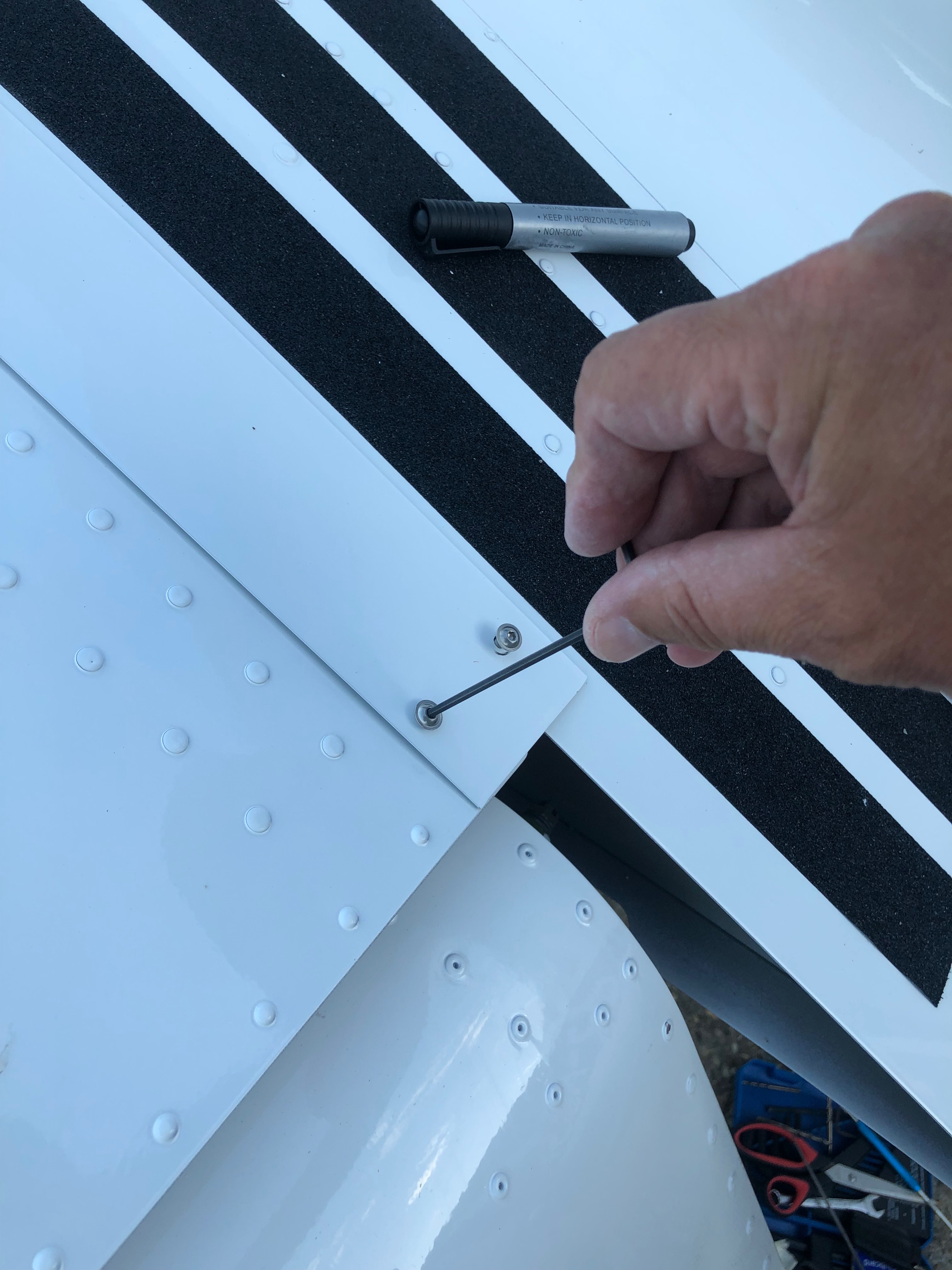
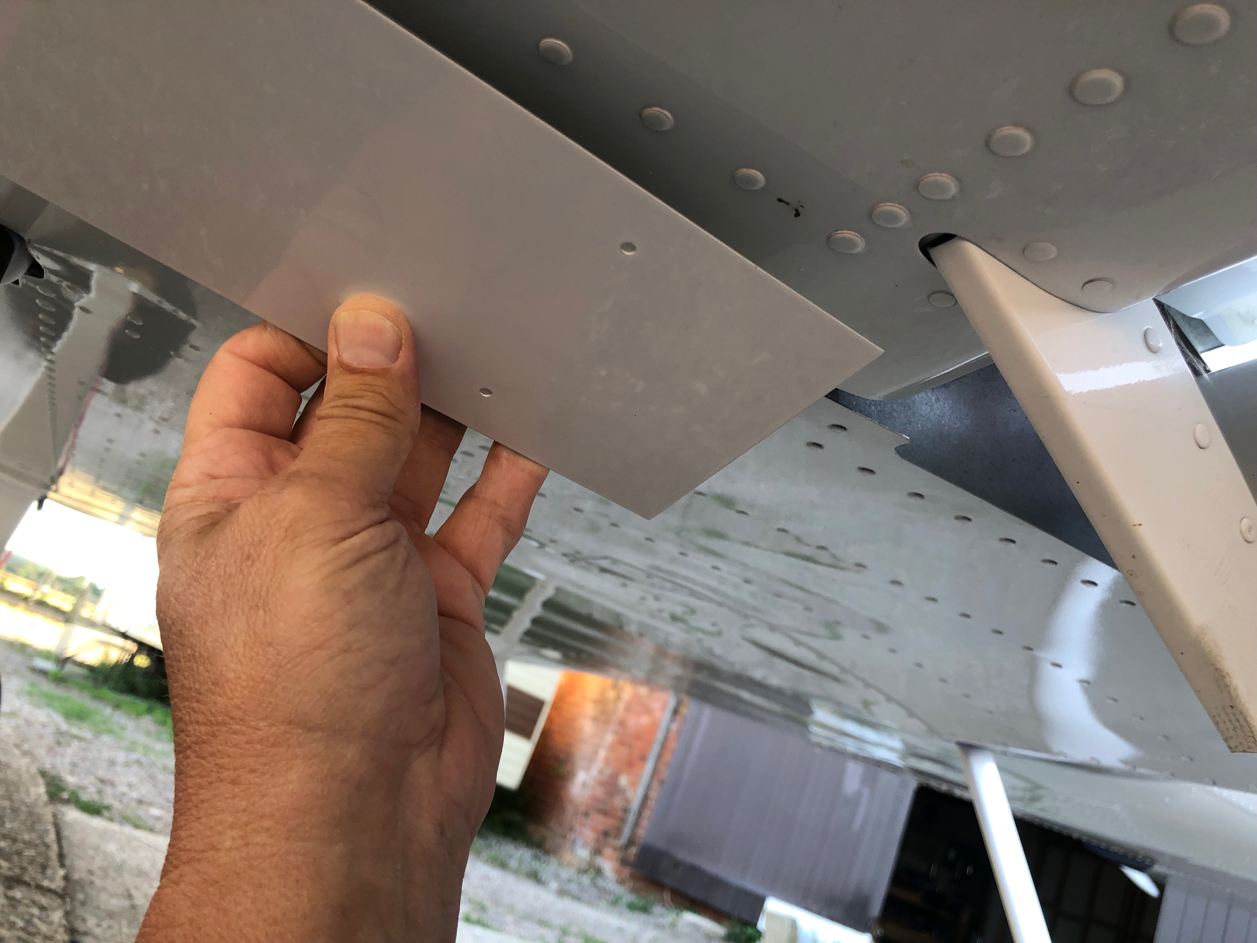
The canopy was temporarily fitted for the engine test so I adjusted the canopy catches and secured the hinge bolts.Next up is sticking the wing walk anti-slip tapes onto the wing root. The area is thoroughly cleaned and degreased to ensure they stick properly. They need to be straight and equally spaced otherwise it’ll look awful. Each tape is carefully placed in position and the backing paper is removed slowly to ensure that it’s parallel with the first tape. The finished job looks quite good.The Bristell’s wings attach to a wing root stub that protrudes from the side of the aircraft. The way the wing joins means that there is a small gap that needs to be covered. A metal joint strip is used which is attached at both ends and pulled together with springs. A couple of Rivnuts are installed on the top of the wing and one end is secured…… the strip is fitted round the front od the leading edge and the springs are added to pull and tension the strip.Finally a couple of Rivnuts are installed on the trailing edge and the joining strip is fixed into position.Quite pleased with final result. It’s important to ensure there is a bit of play in the fixing holes otherwise the strip may buckle and it won’t be flat on the wing. G-MLSY in it’s new home for now. Just the spats to fit now and then the external features of the aircraft will be complete.
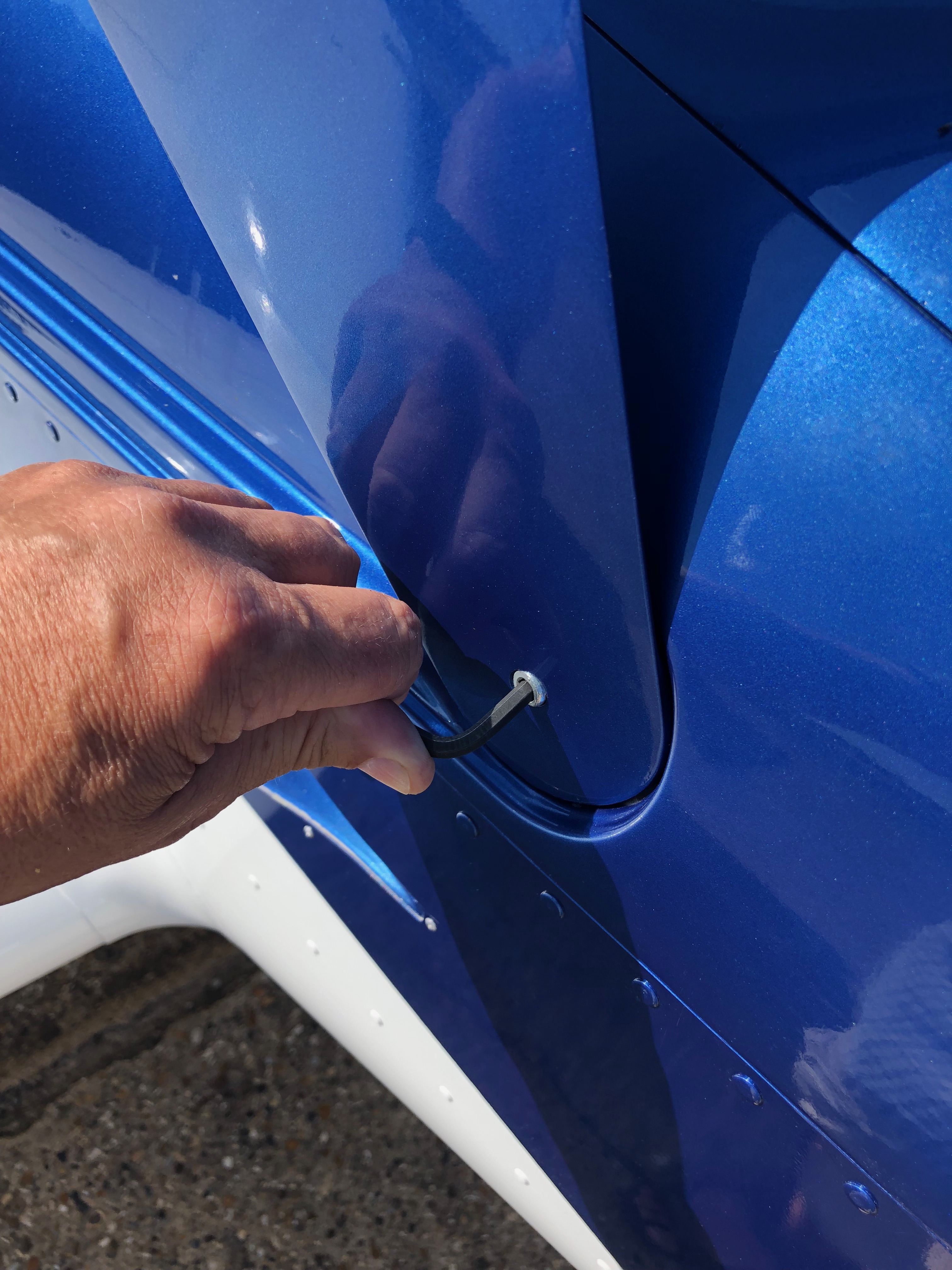
Didn’t do a lot today as I was expecting a couple of special visitors but I did want to revisit the canopy release mechanism as I thought about its operation and how I would open the canopy if the mechanism didn’t work.
A visit today from Kilo Sierra and…Gill and Steve Lynn to visit me and see the progress on G-MLSY.A bit premature to put the cowlings and spinner on but Steve was taking some photos and I thought it would be good to see it all dressed up.After a great catch up and some fish and chips on Tankerton slopes it was time to make their way back to Dunstable.The cabin release wasn’t quite operating as it should so I shortened the operating wire so that it acted earlier in the operation.
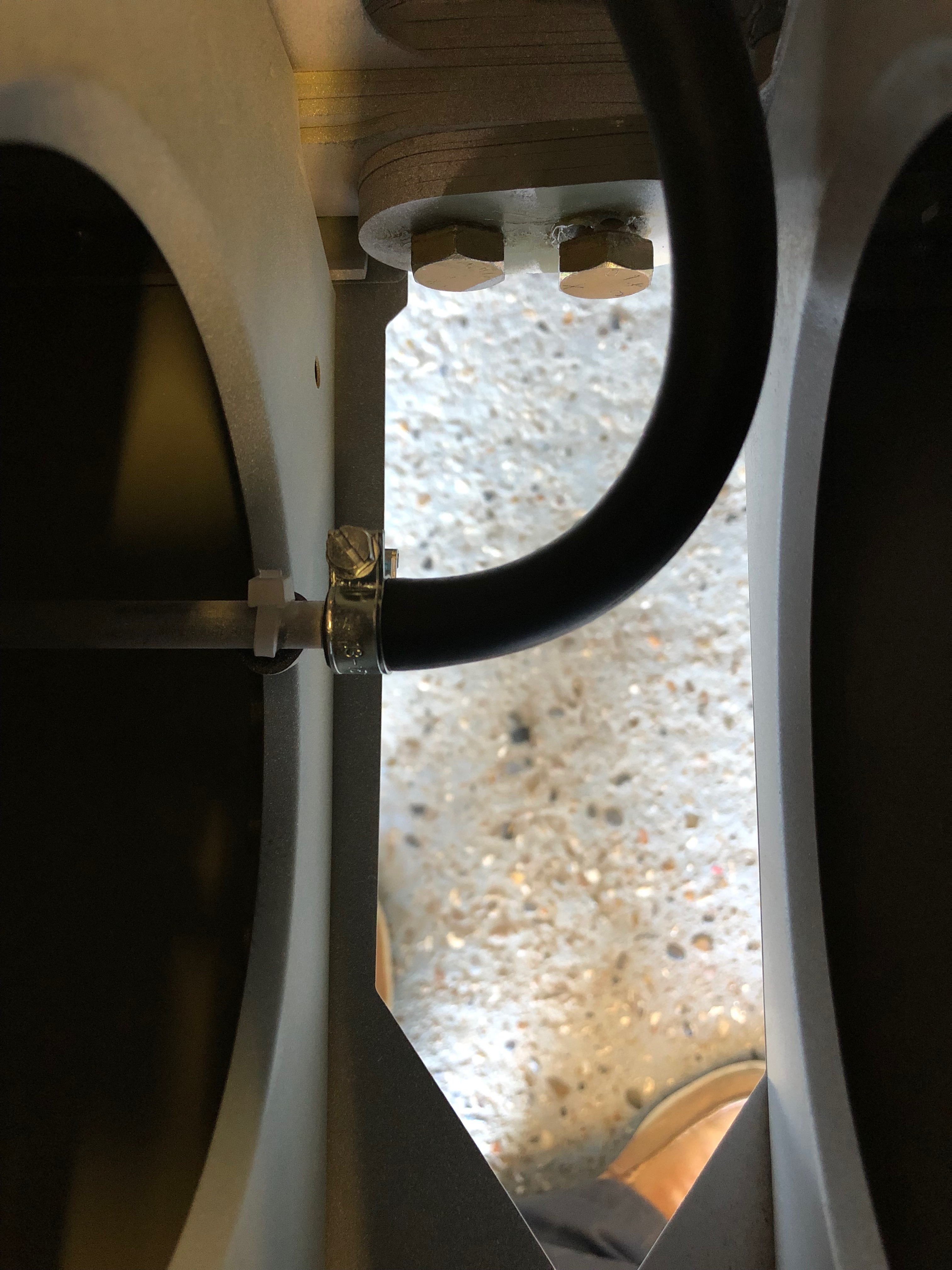
Short day today so just a couple of items. The first thing for today was setting the trim speed so it falls within the acceptable stop to stop time limits for the LAA followed by fitting the fuel pipe between the wing tanks and fuselage and finishing off by driving the holes for the LEMO plugs for the Bose headsets and fitting the rear trim panel. Also called CFS to see if my floats for the Rotax engine need changing as there has been a fault that’s been affecting them for 5 years now. You’d think they’d have sorted it out by now eh?
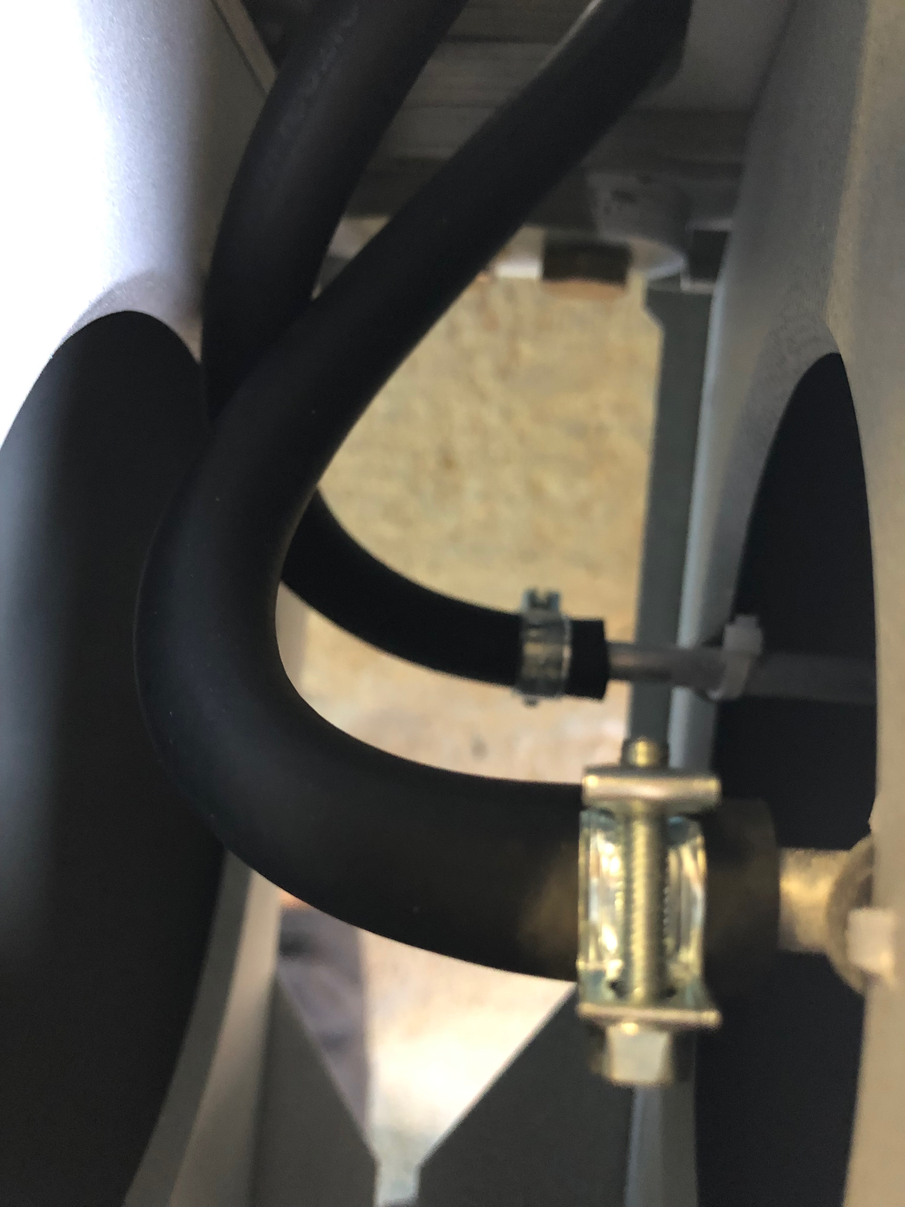
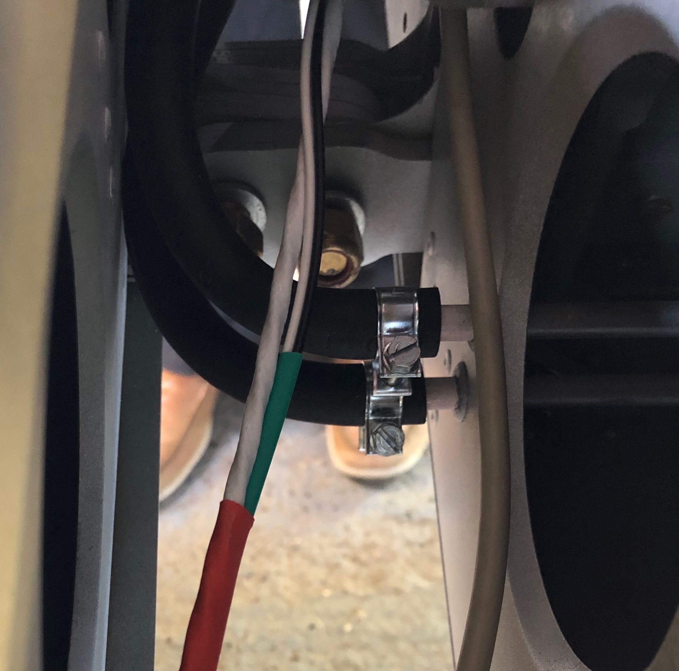
The starboard wing has a single pipe that runs from the fuel tank in the wing to the fuselage. It’s quite a tight fit so need to make sure it doesn’t kink and it’ll need protecting with some sheathing.The Port wing fuel tank has two pipes one for supply and one for return. When starting the engine it’s important to select the Port fuel tank as any surplus fuel is returned to that tank. If it’s already full it will overflow. Must make sure you don’t get the supply and return mixed up!The feed and return pipes from the fuselage. The bottom one is the return.I’ve already fitted the centre canopy release mechanism so all that is required is to drill and shape the two holes for the LEMO headset sockets. They fit from underneath so they can be fitted with the sockets already attached.Last job of the day is to fit the rear trim panel. I decided to make the panel removable so Rivnuts and screws are used to secure.
Monday was set aside to travel to Chilsford Farm to collect some of the outstanding items from the kit. So today I could get on with a lot of jobs that had stalled because of the shortages.
On Friday I sealed the canopy perspex with silicone and left it to set. The waste material was removed with a plastic scraper.
And cleaned off with some methylated spirits.
The result is good but not perfect in a couple of places so will need some attention once the canopy is mounted.
Next up is to connect the NACA ducts to the various intakes on the carburettor and cabin heater.
The SCAT ducting for the air intake is secured with a jubilee clip onto the air intake.
The ducting is cut to size and attached to the rear of the righthand NACA inlet on the lower canopy.
The heat exchanger is positioned and secured in place with large jubilee clips.
A short piece of ducting is installed between the heat heat exchanger and the heater intake that runs through the firewall to provide cabin heat and a de-mist facility.
A long pice of ducting is connected to the heater control and will eventually connect to the glare shield that includes the de-mist vents.
The lefthand side ducting runs from the NACA inlet to the middle heat exchanger connection but it’s quite tight so it must be routed so it doesn’t come into contact with the exhaust system.
View from the righthand side.
A spring is cut and installed to ensure that the air intake is supplied from the cold air vent by default.
One of the items I picked up on Monday was the pitot mount. I’ve already taken delivery of the avionics so I can mount the pitot onto the mount.
Instead of drilling holes and using screws I’ve decided to secure the probe into position with silicone which will provide a neat solution.
Once filled with silicone it’s left to set overnight.
The carburettor air box has two ‘horns’ that the SCAT hose connects to. They require sealing with heat resistant silicone and secured with three rivets.
The finished air box which will be left to set overnight.
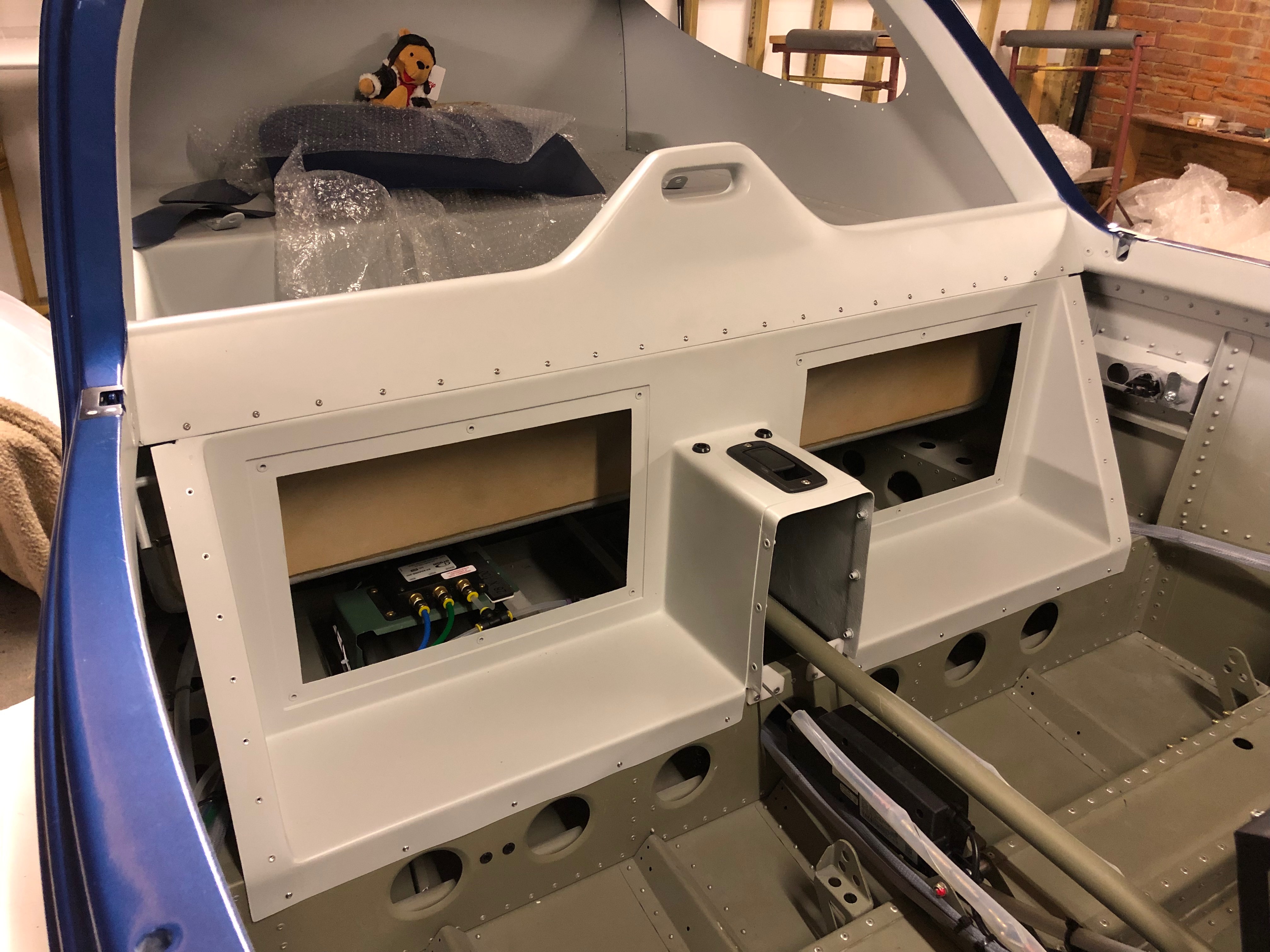
The cabin air vents are supplied with fresh air from NACA ducts in the side of the fuselage. They require installing in the instrument panel and then connecting up with some scat hose. So a temporary fit of the panel is required to get the hose length.
Two brackets are clecoed into position and the panel is secure by two screws each side.
With the panel installed it give me an idea of the space I have for the avionics and possible positioning. Tomorrow I will fit the air vents and hose.
One job left over from installing the fuel system is to fit the fuel pressure sensor. The sensor cannot be connected directly to the hose. A 1/8″ NPT female to 6mm barb adapter is required.
As it will come into contact with fuel Loctite 577 is used to seal the thread before fitting.
The pressure sensor and adapter before being screwed together. They will be left overnight to set.
The final job for today was to trim the cowl to ensure is doesn’t come into contact withe the water radiator.
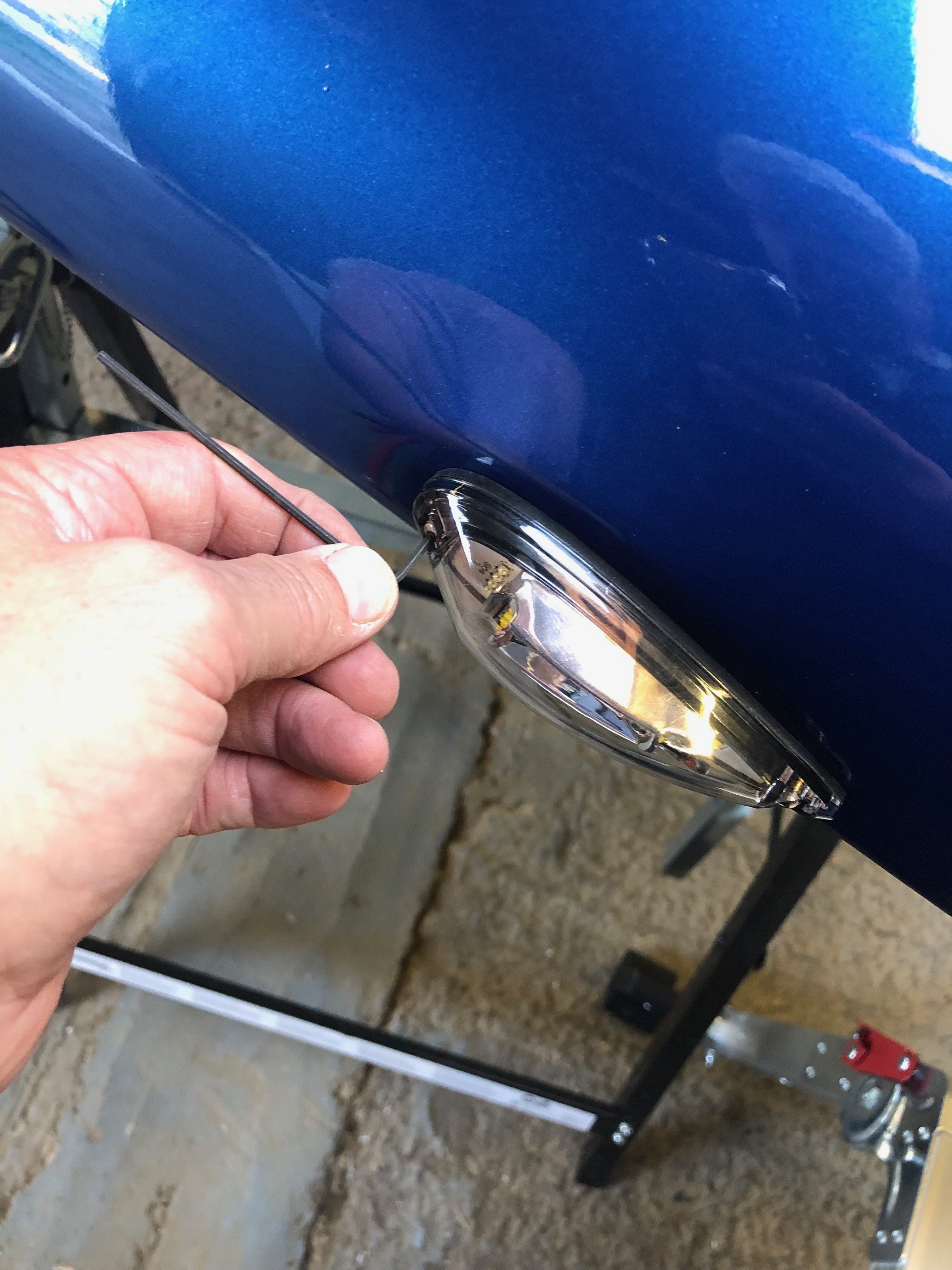
Today I completed the installation of the right wing landing lights and strobe light and as it was quite warm today I decided to seal the canopy plexiglass with the silicone sealer.
The landing lights covers have to be a flush fit so countersunk M4 rivnuts are used to facilitate this.
When installing the rivnut it’s important to ensure that it’s not installed at an angle.
The starboard landing light and cover complete.
As it’s been a warm day I thought it would be a good time to seal the plexiglass. It has already had a first fit at the factory but needs sealing with silicone before it can be used in service.
The channel is filled in a similar way to sealing around a bath!
Once the channel is filled it needs to be smoothed. It’s suggested that the back of a spoon is used. If pressed hard enough it will leave two lines either side of the filled channel. This allows the waste material to be removed when it’s set in a couple of days.
The finished canopy. The waste material will be removed on Monday or Tuesday.
Next is to fit the starboard strobe. The cable need to be soldered and as with the port wing the wire colours are different so a record needs to be kept for the wiring records.
There is a flat section for the strobe but no definite location is marked so the strobe needs to be positioned to what looks ‘right’.
The holes are drilled and M3 countersunk rivnuts that I purchased this morning from DJ Invicta Supplies are installed and the light is secured with M3 stainless steel button head screws.
The starboard lights complete I’ll leave the wing on the stand ready to install the Pitot on Monday once I get the pitot mount from Farry.
After some exciting skiing in Val Thorens it’s back to work. Whilst I was away I planned my weeks ahead based on what’s left to do. Some small jobs to get me back into the groove.
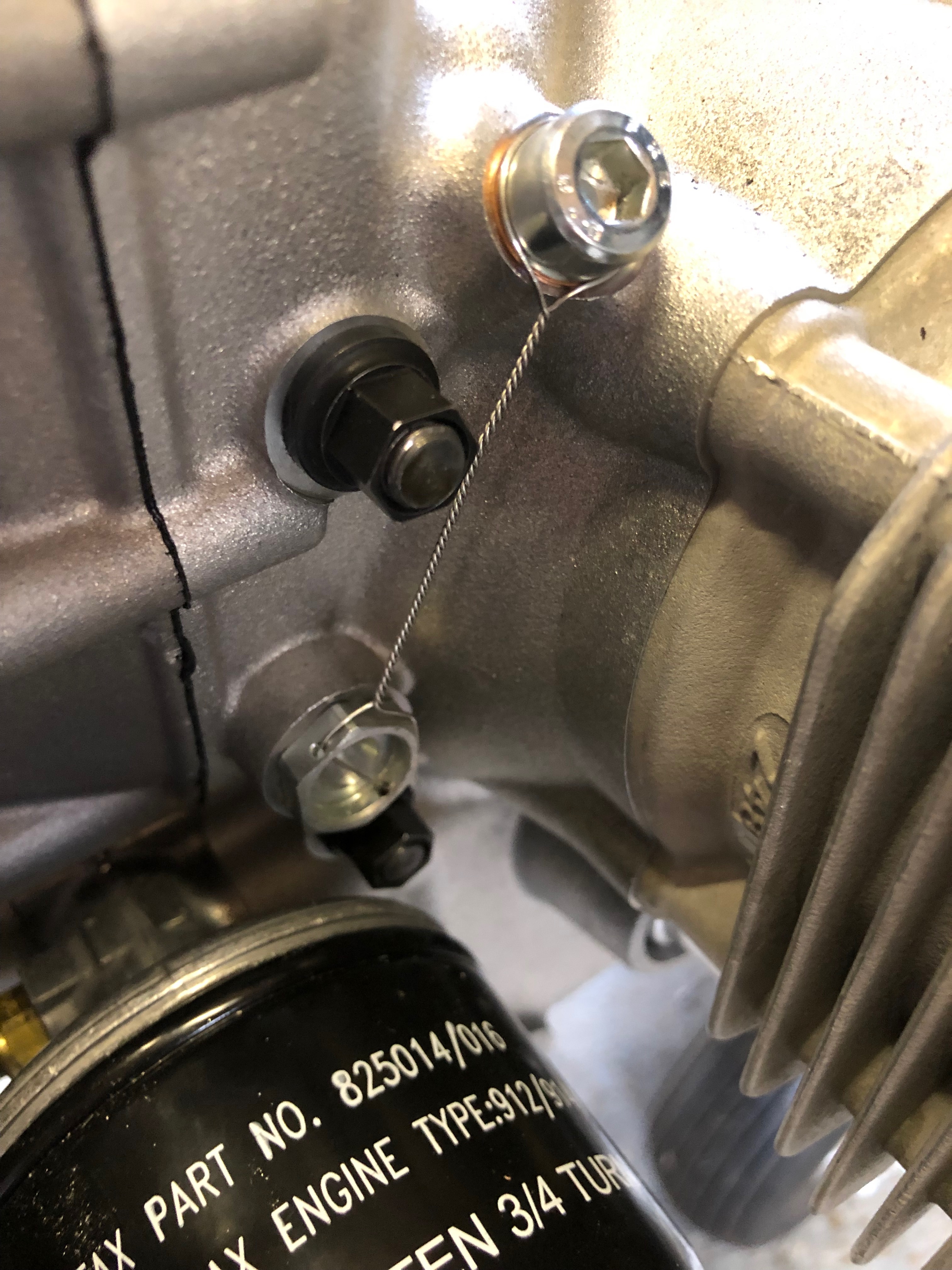
The magnetic oil plug needs to be checked for debris. If any large pieces of metal are stuck to this it’s an indication that there is a problem with the engine.
Once checked the plug is refitted and locked to prevent it from coming loose whilst in operation.
The oil drain banjo underneath the engine also needs to be wire locked.
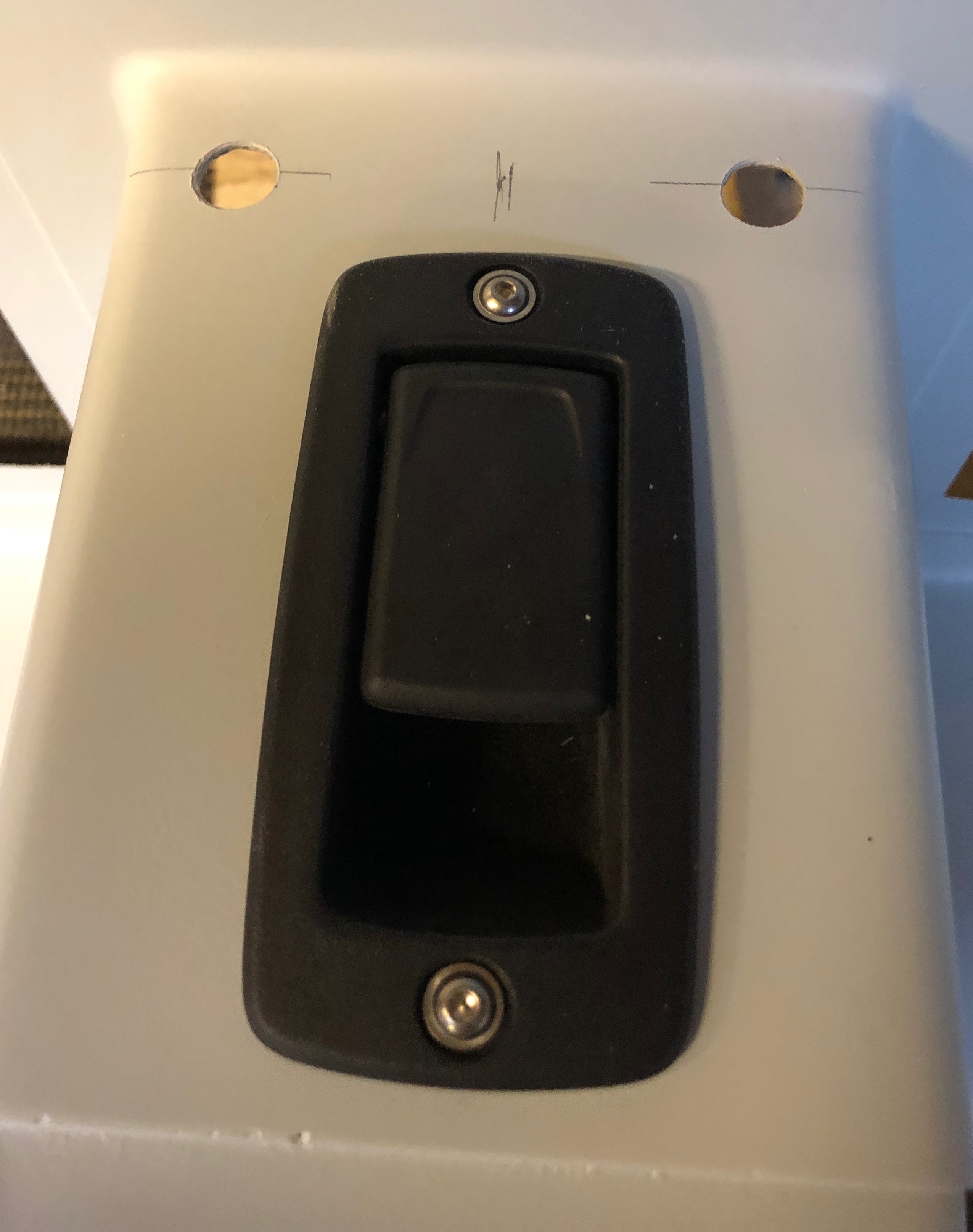
A job leftover from fitting the canopy locks is installing the centre canopy release mechanism.
Holes marked and drilled.
A rivnut is installed and the mechanism is secured. Once the interior panels are fitted the operating wire will be fitted.
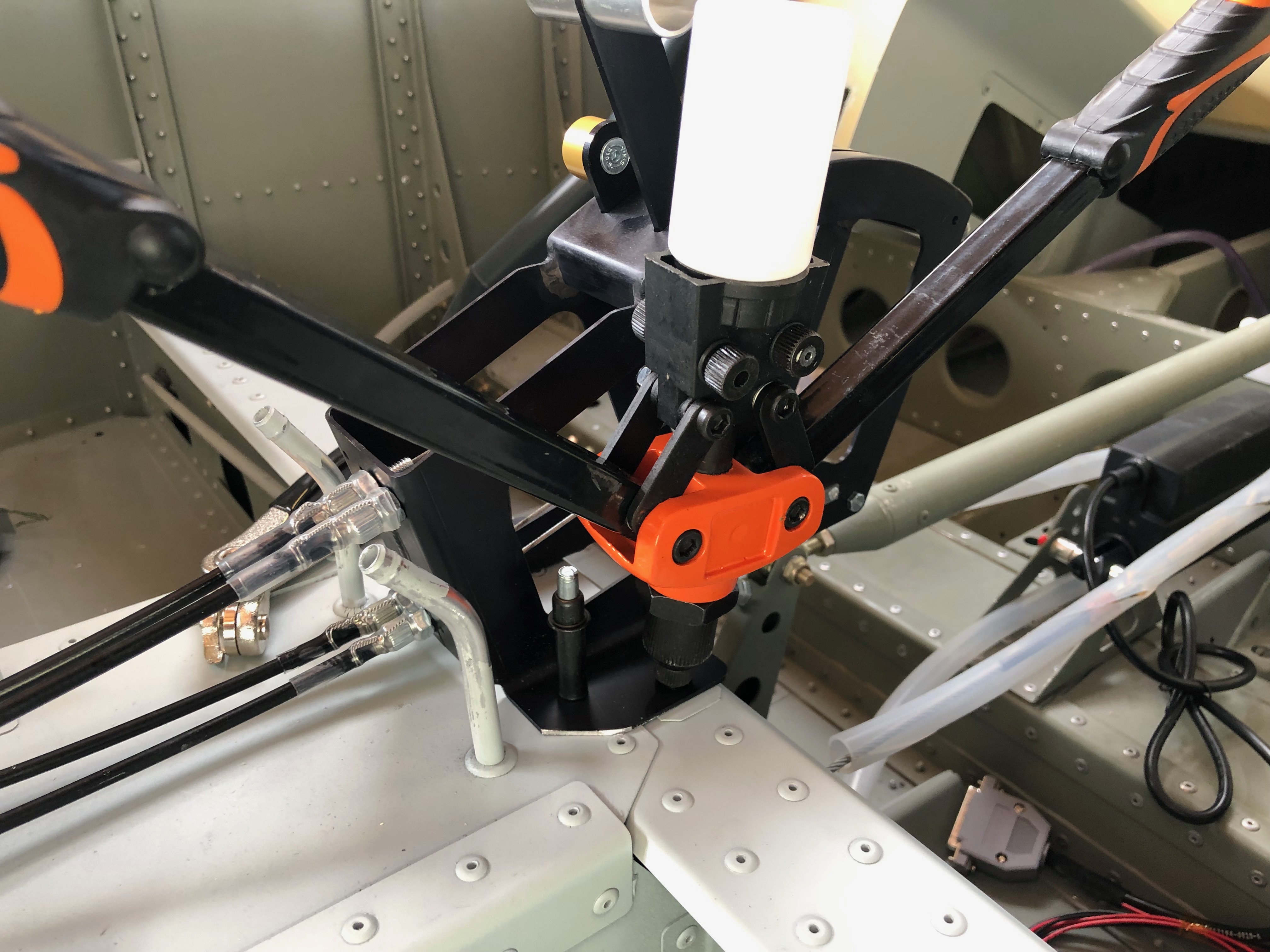
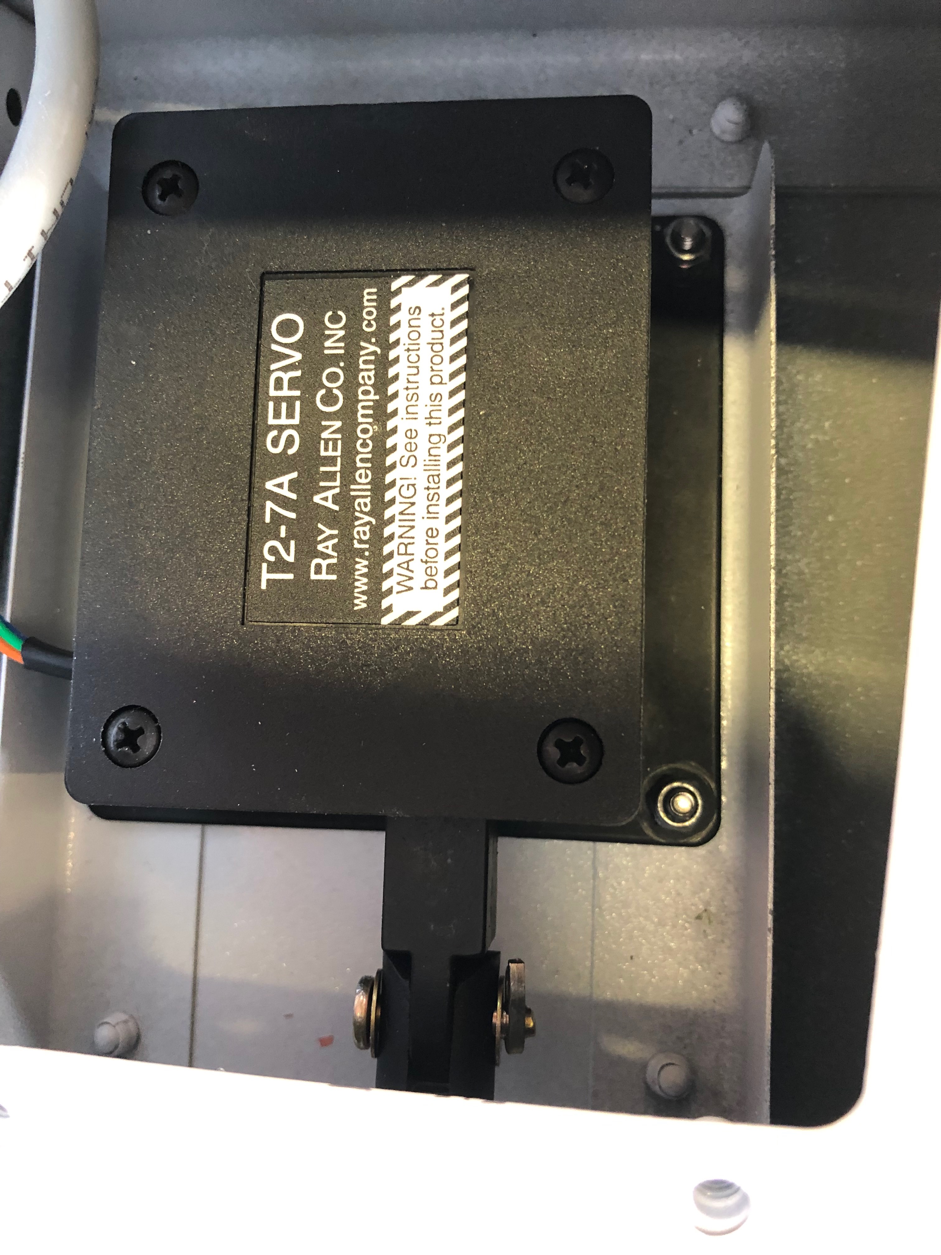
When Chris came down he helped me install the electric aileron trim servo. Now it’s time to install the Elevator trim mechanism. Chris had already attached the clevis, pin, split pin and had cut the threaded rod which cuts some of the work I have to do.
The first thing that needs to be done is to set the trim motor to its extremes so it can be set at midpoint.
The midpoint is 8.5mm which is set by connecting to a 12v battery to move it to that position.
The servo is temporarily installed with Clecos, the other clevis is attached and adjusted so the trim tab is inline with the elevator.
The Clecos are removed and M3 screws, nylon washers and nylocs nuts are used to secure the servo.
Once correctly adjusted the pin and clevis is secured with a split pin.
Today focuses on finalising some of the work I had already started but was waiting on parts.
First up is to rivet the throttle into place.
A view of the throttle installation from the top.
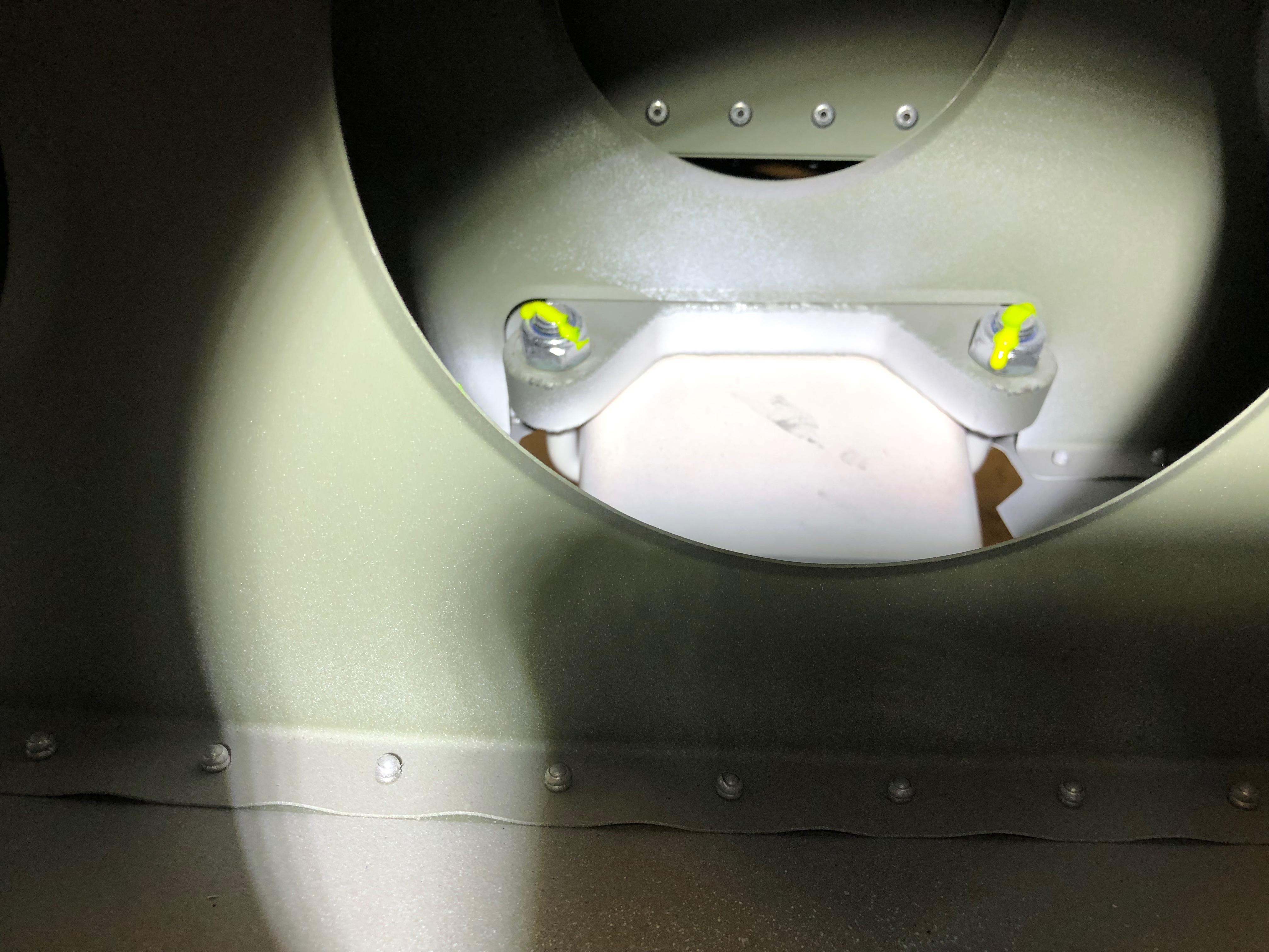
Next is to replace the 5/16″ bolts that were found to be damaged.
Once tightened the nuts are marked with torque seal to indicate any movement in service.
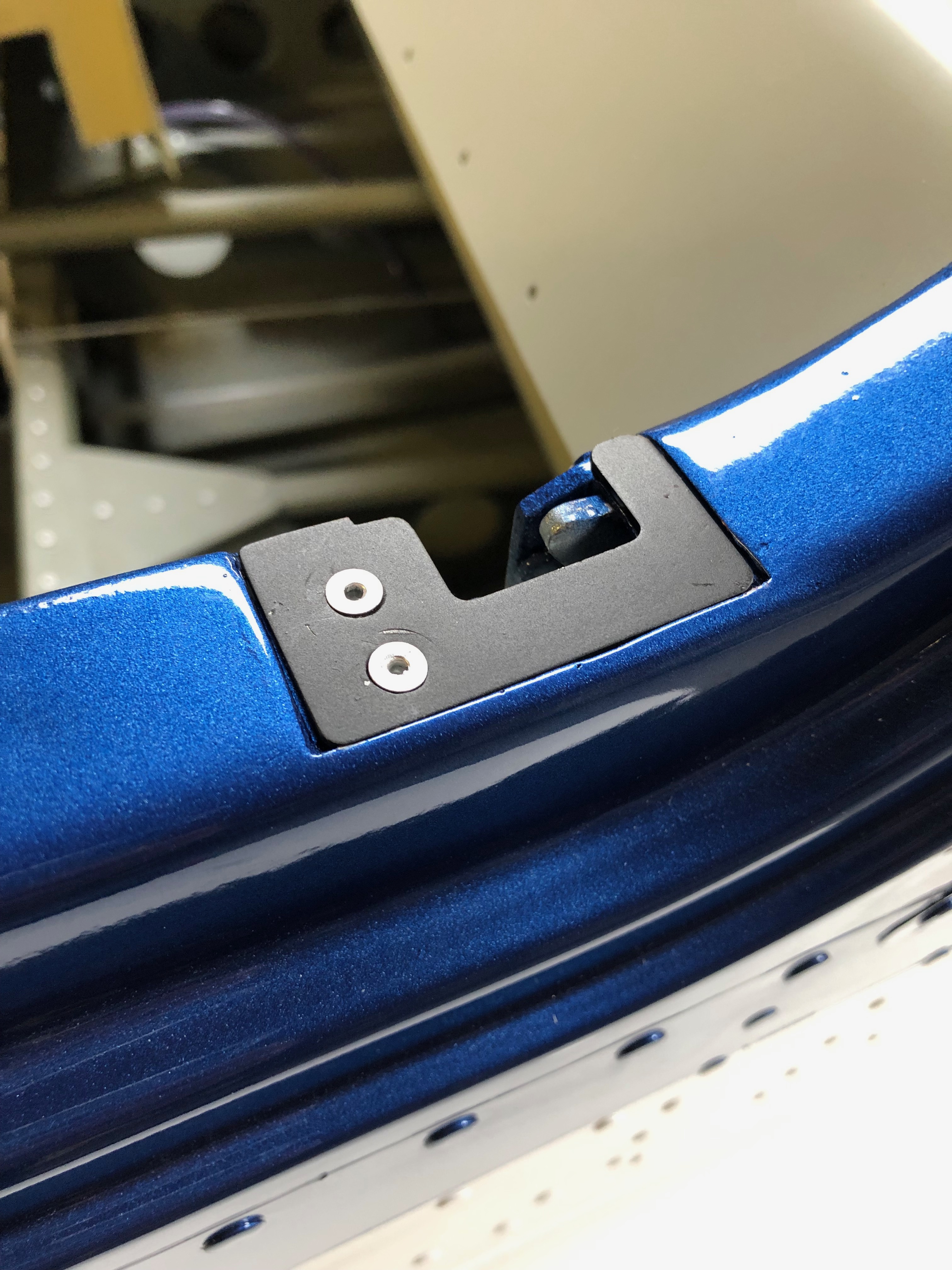
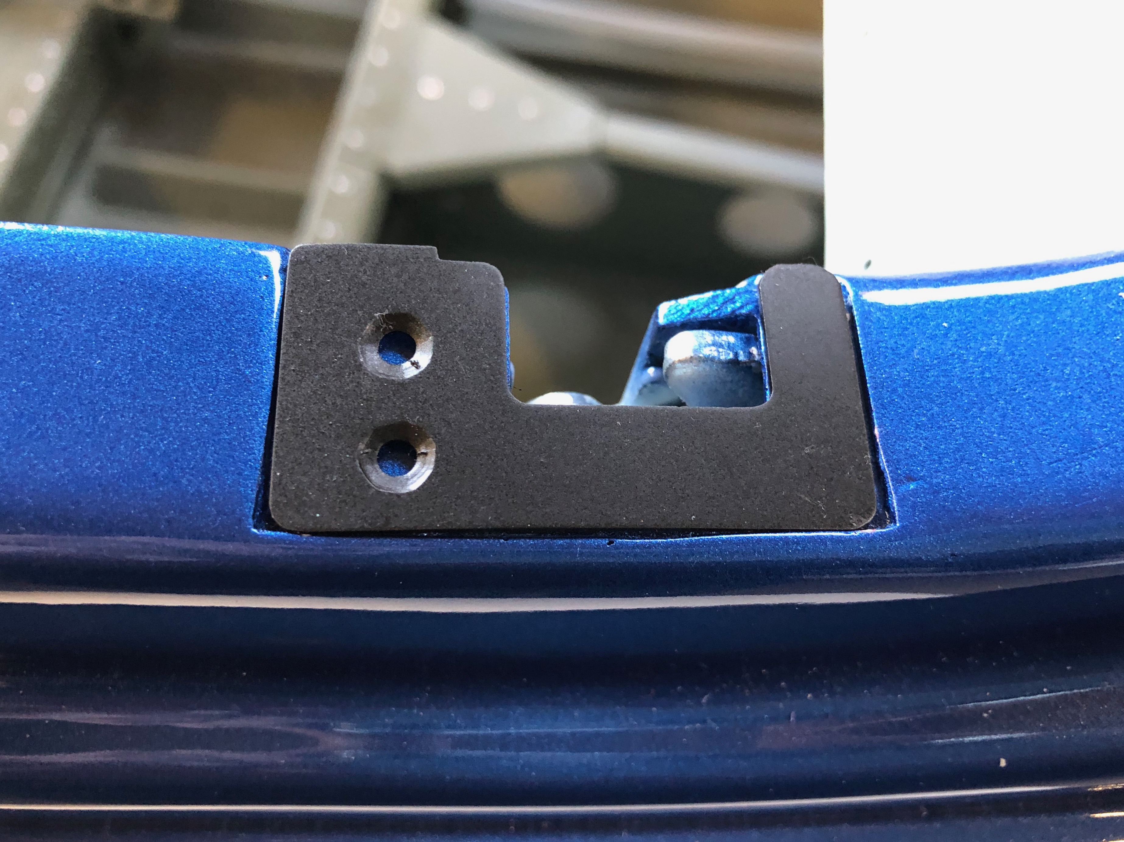
The canopy latch striker plates are riveted into place.
And the spring return plate is riveted into place and the spring connected.
The trim motors are normally riveted into place but I’ve decided to use an M3 bolt and nyloc bolt as it will be easier to change should there be a problem.
The wiring needs to be done next but I’ll leave that for another day.
A number of jobs today including some to finalise previously started installations.
The throttle quadrant was cleco’d in position temporarily to allow the cables to be run. This needs to be riveted with 4mm x 15mm rivets which I need to purchase.
The temporary holes were 3.2mm so I’ll open them out ready for riveting tomorrow.
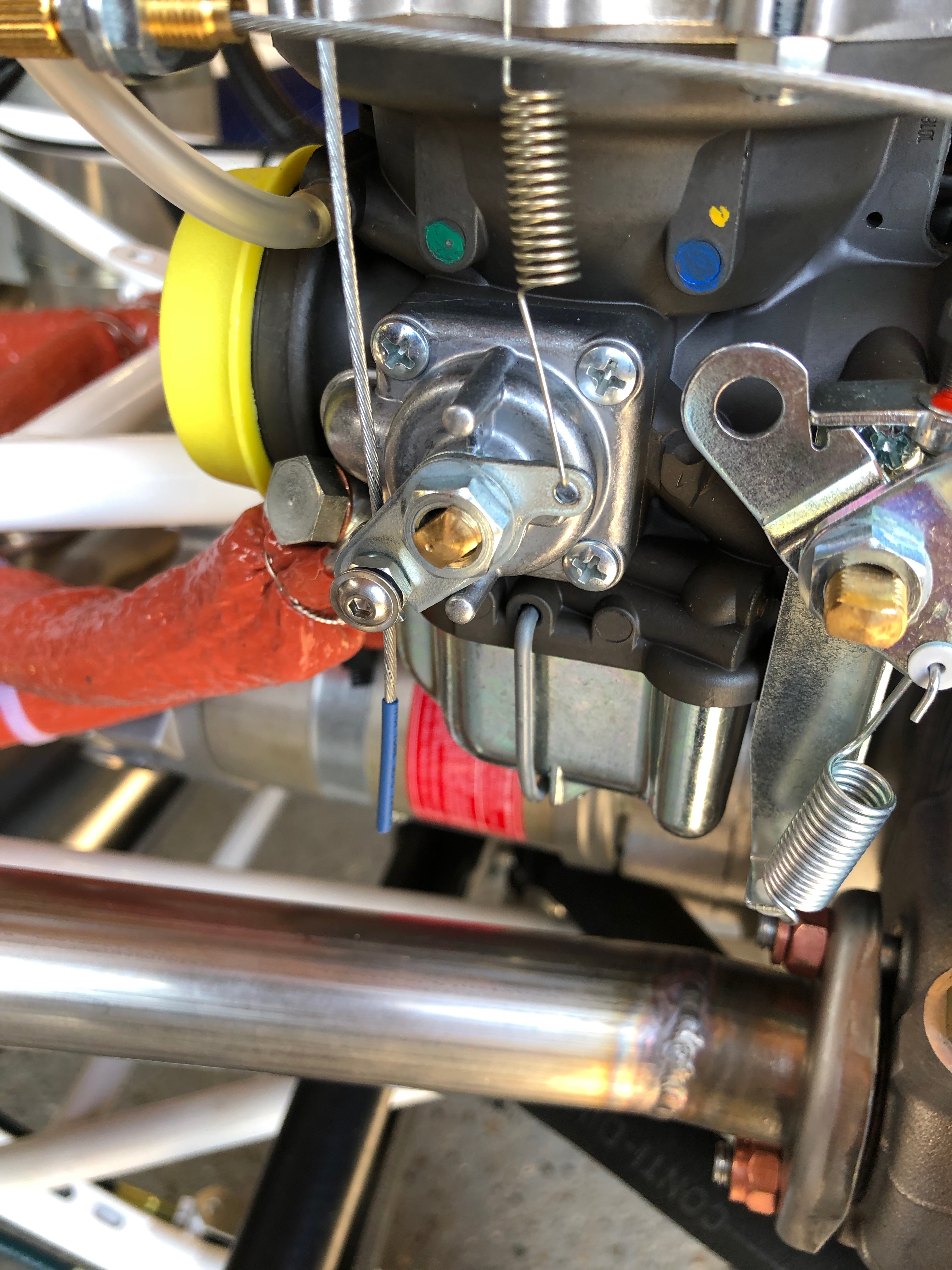
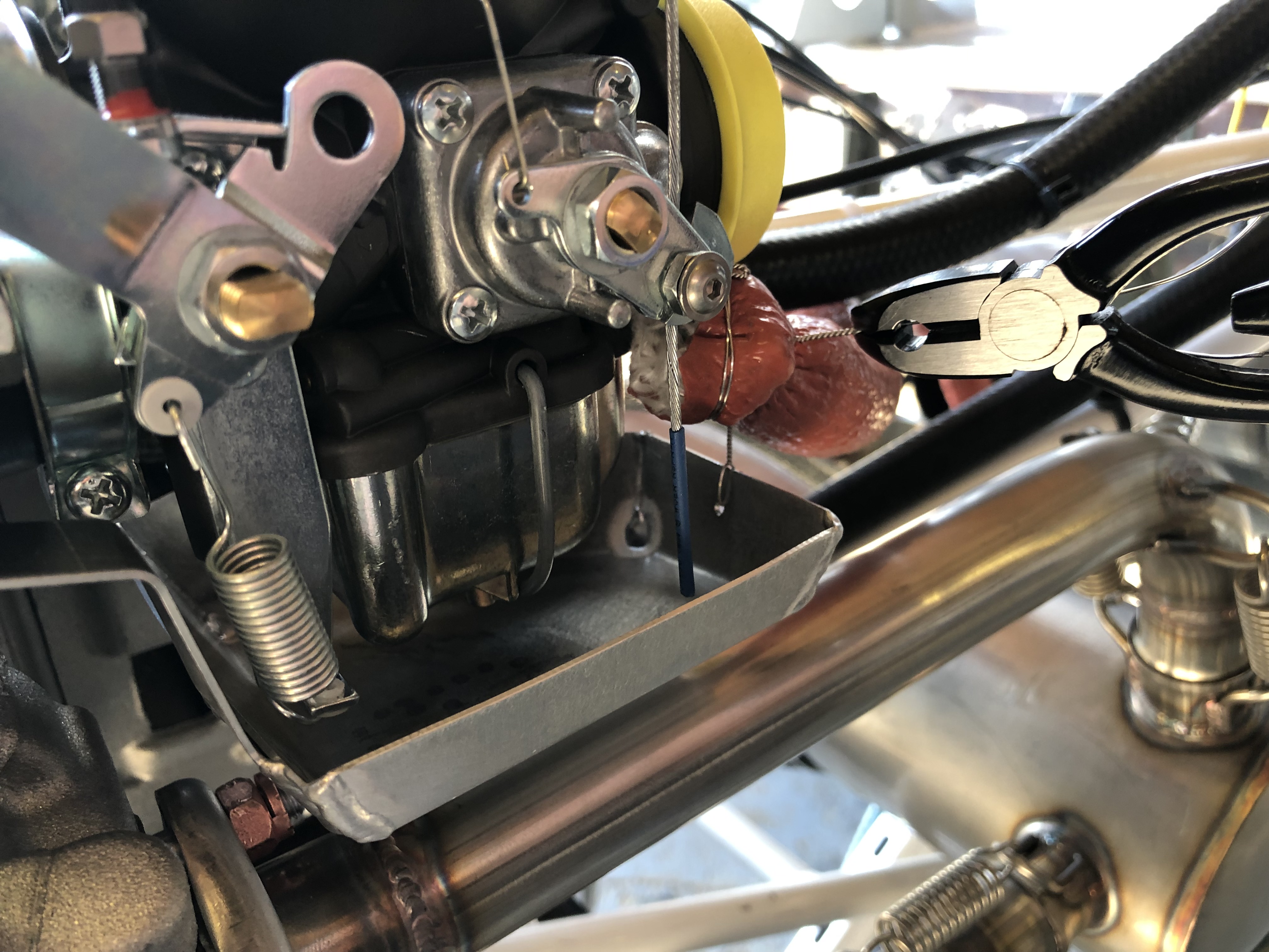
The throttle and choke cables need to be adjusted, tightened and cut to length.
A small piece of heat shrink is put on the end to stop it fraying in service before it is cut to size.
The drip trays are held in position by a bracket at one end and a piece of wire lock at the other. A small hole is drilled in the drip tray to facilitate.
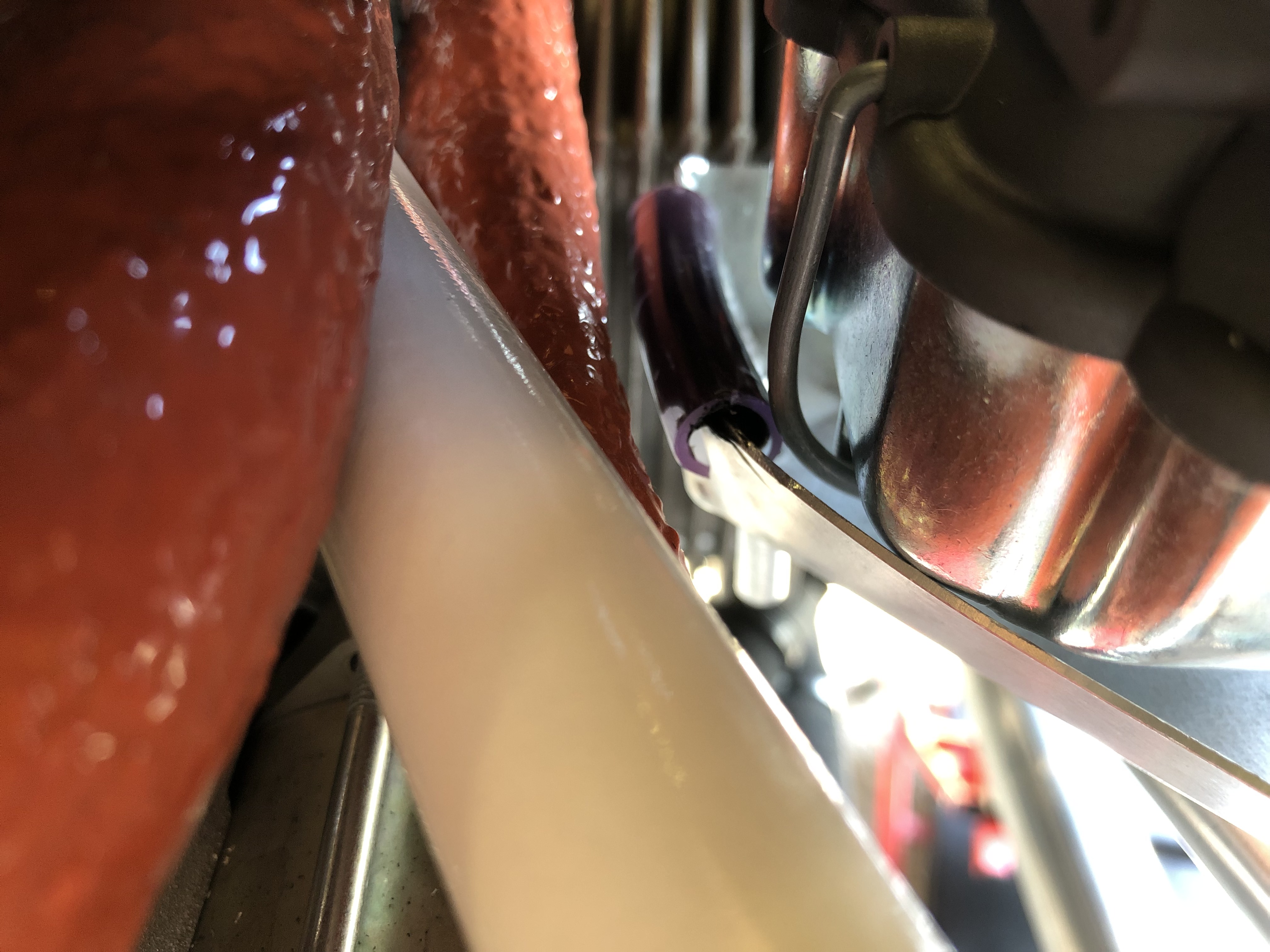
The right hand tray is quite close to the fuel line so a small modification was made to the tray itself and a small piece of plastic tubing secured on the top of the tray to stop it rubbing on the pipe.
View of the final installation.
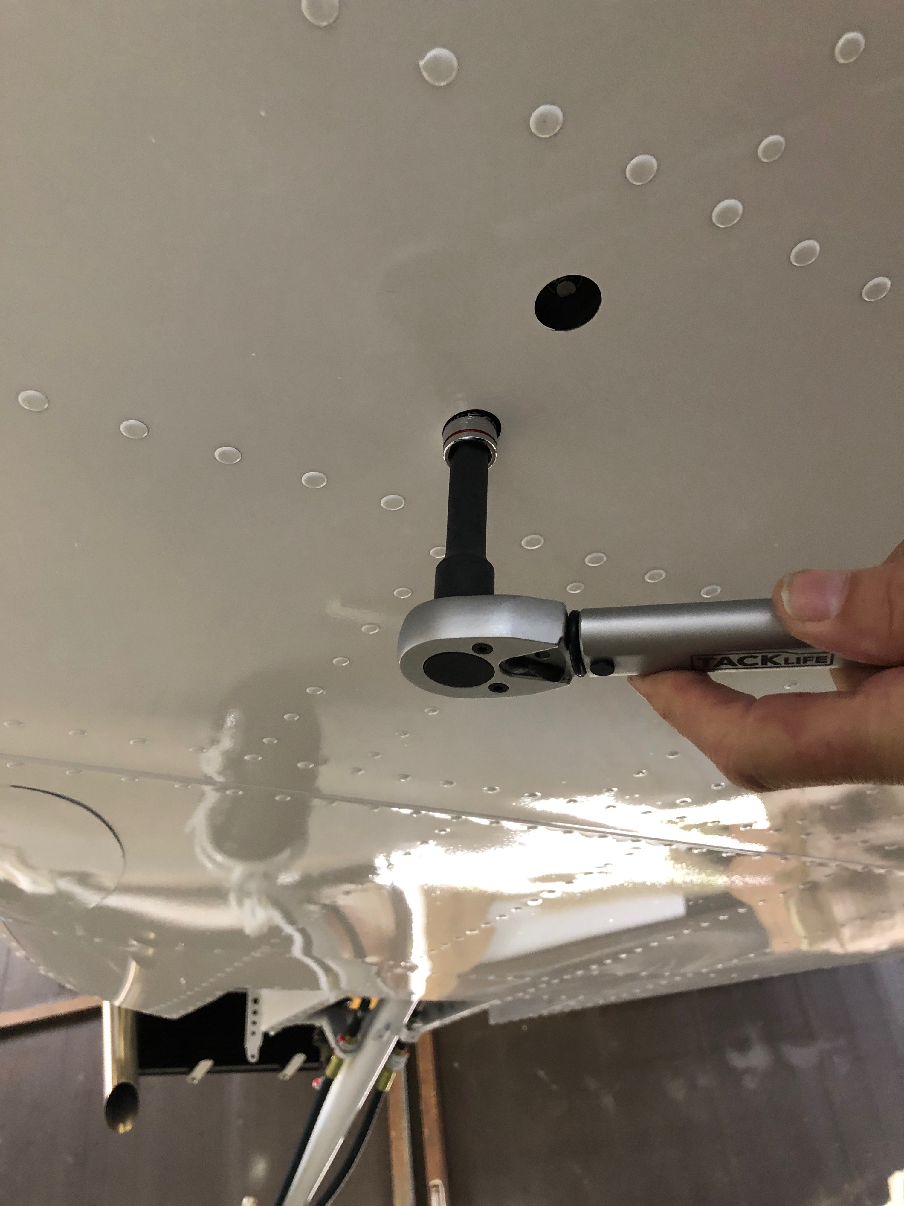
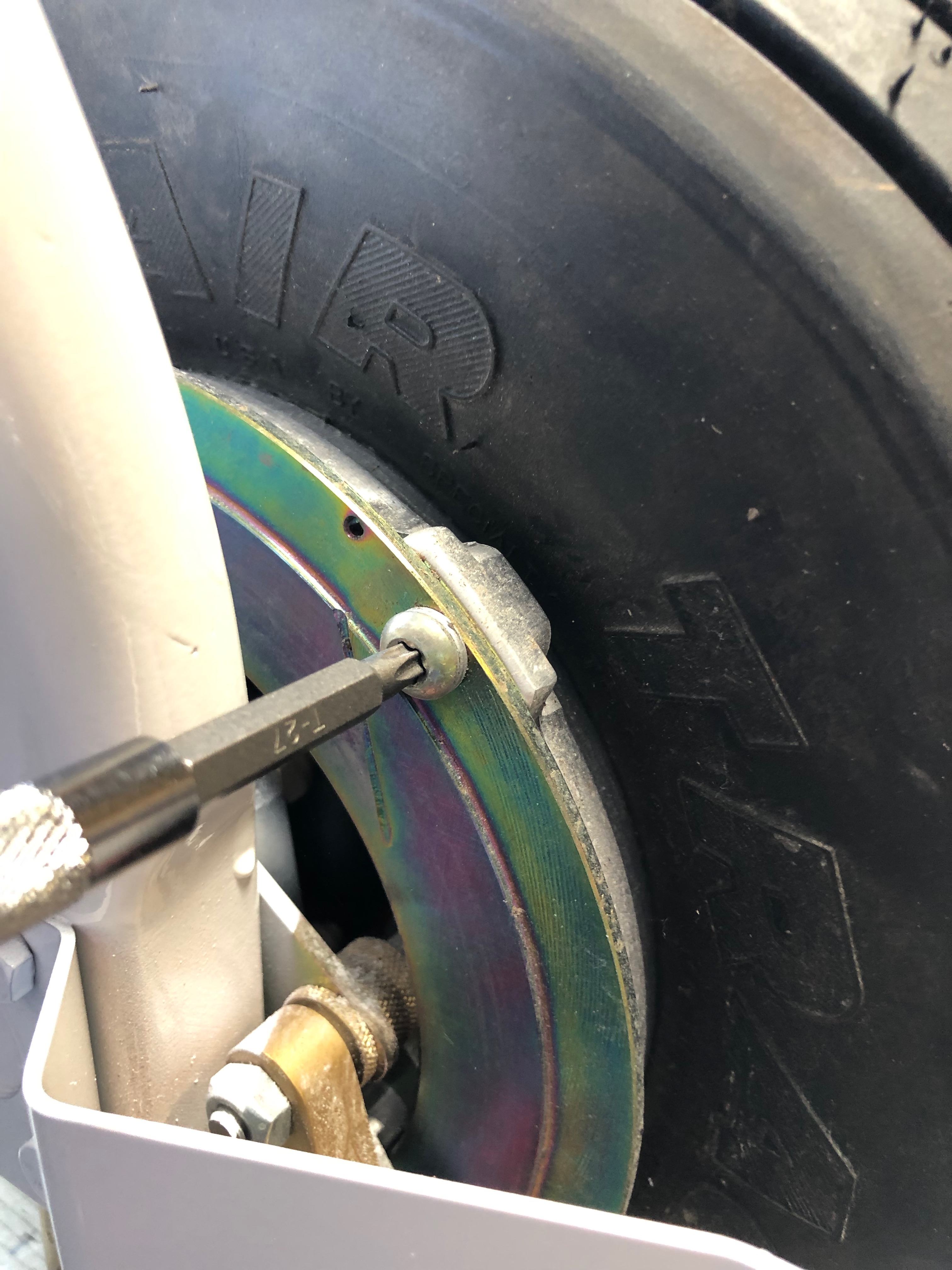
One of the jobs on my ‘todo’ list was to torque the brake disks so the wheel is jacked using a simple wooded jack.
The bolts are torqued…
and marked with torque seal. This will allow me to see if there is any movement in the bolts whilst in service.
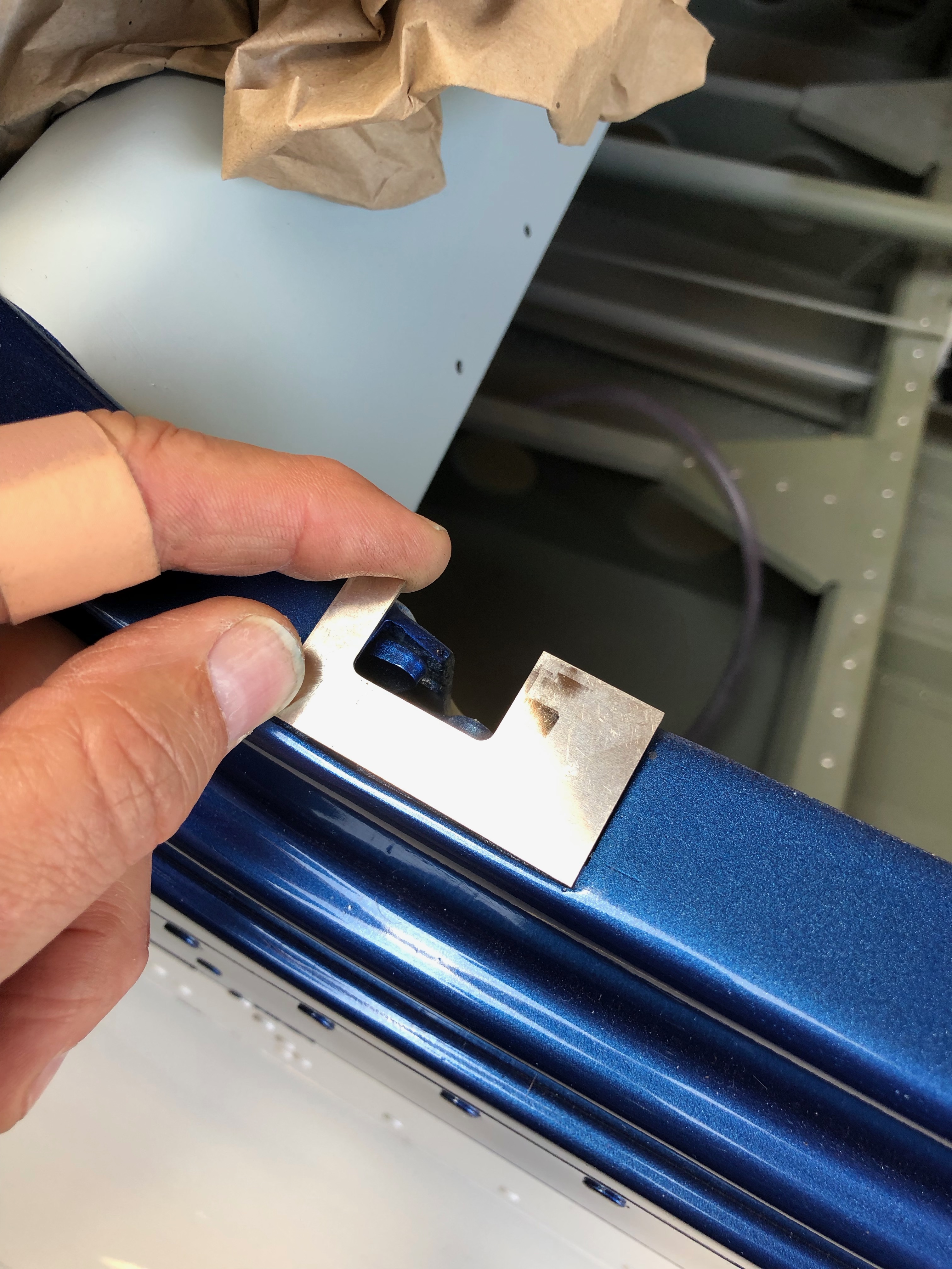
Next job to do fit the canopy locks and striker plates.
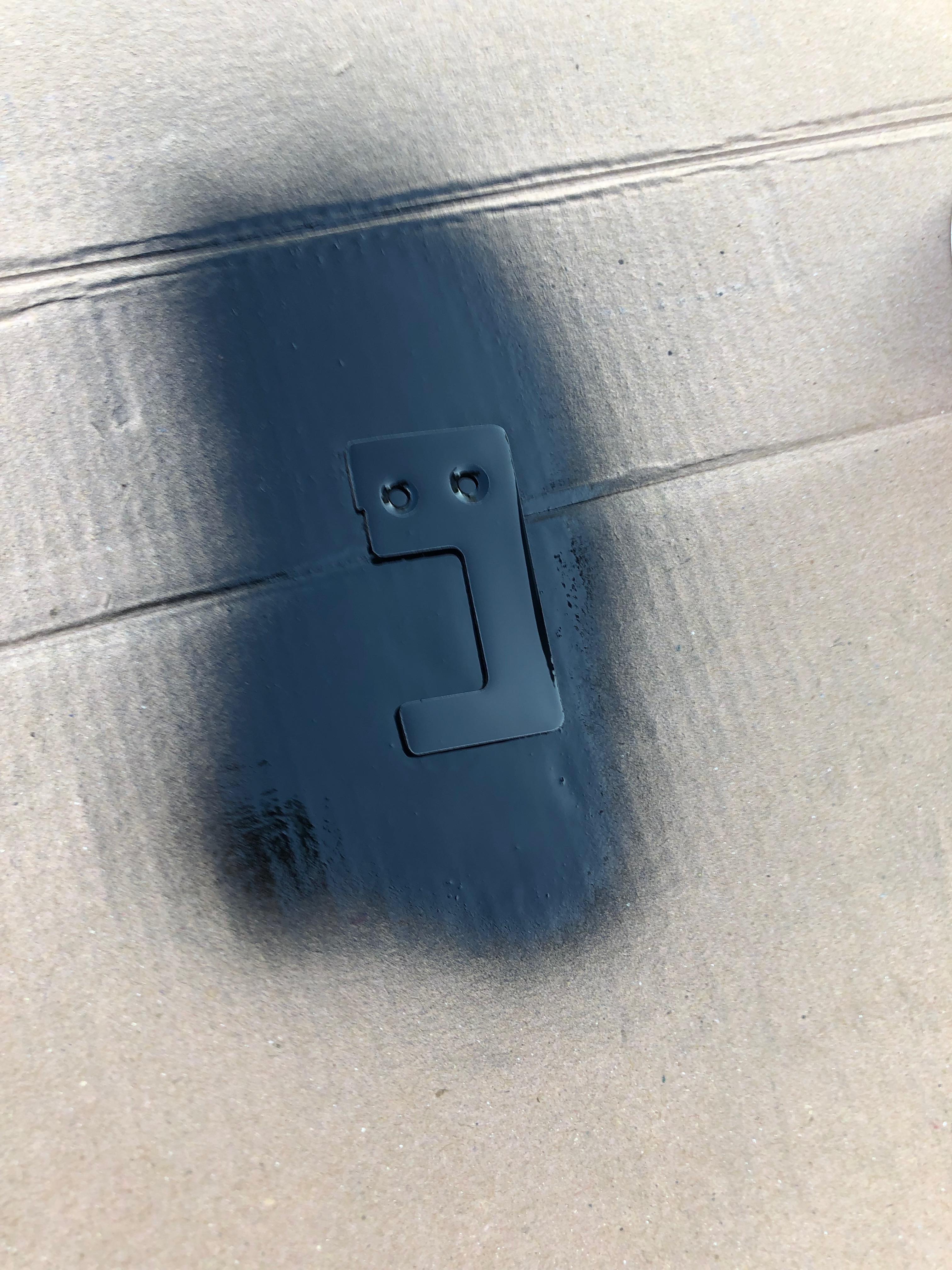
Once cut to size, holes countersunk and smoothed off they can be painted.
The striker plate in place ready to be riveted into place tomorrow.
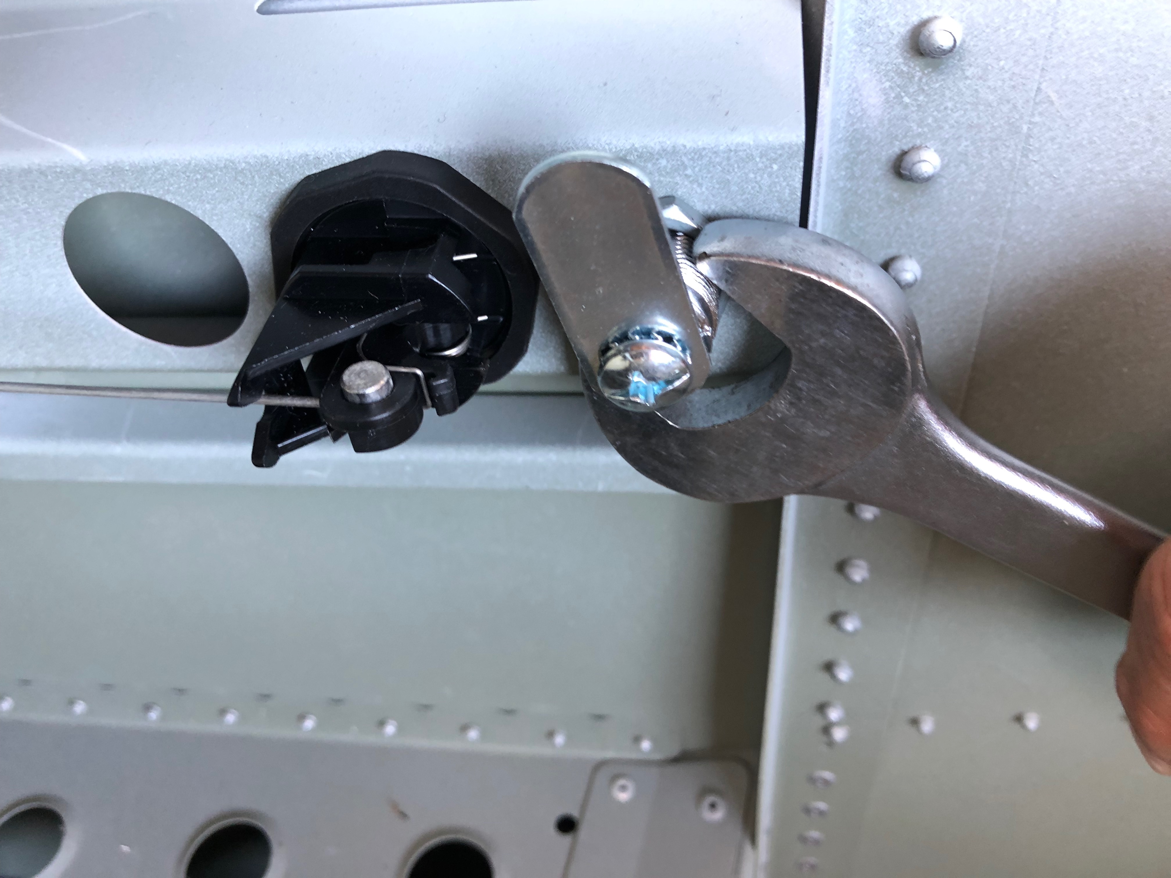
The canopy lock and release are installed and tightened.
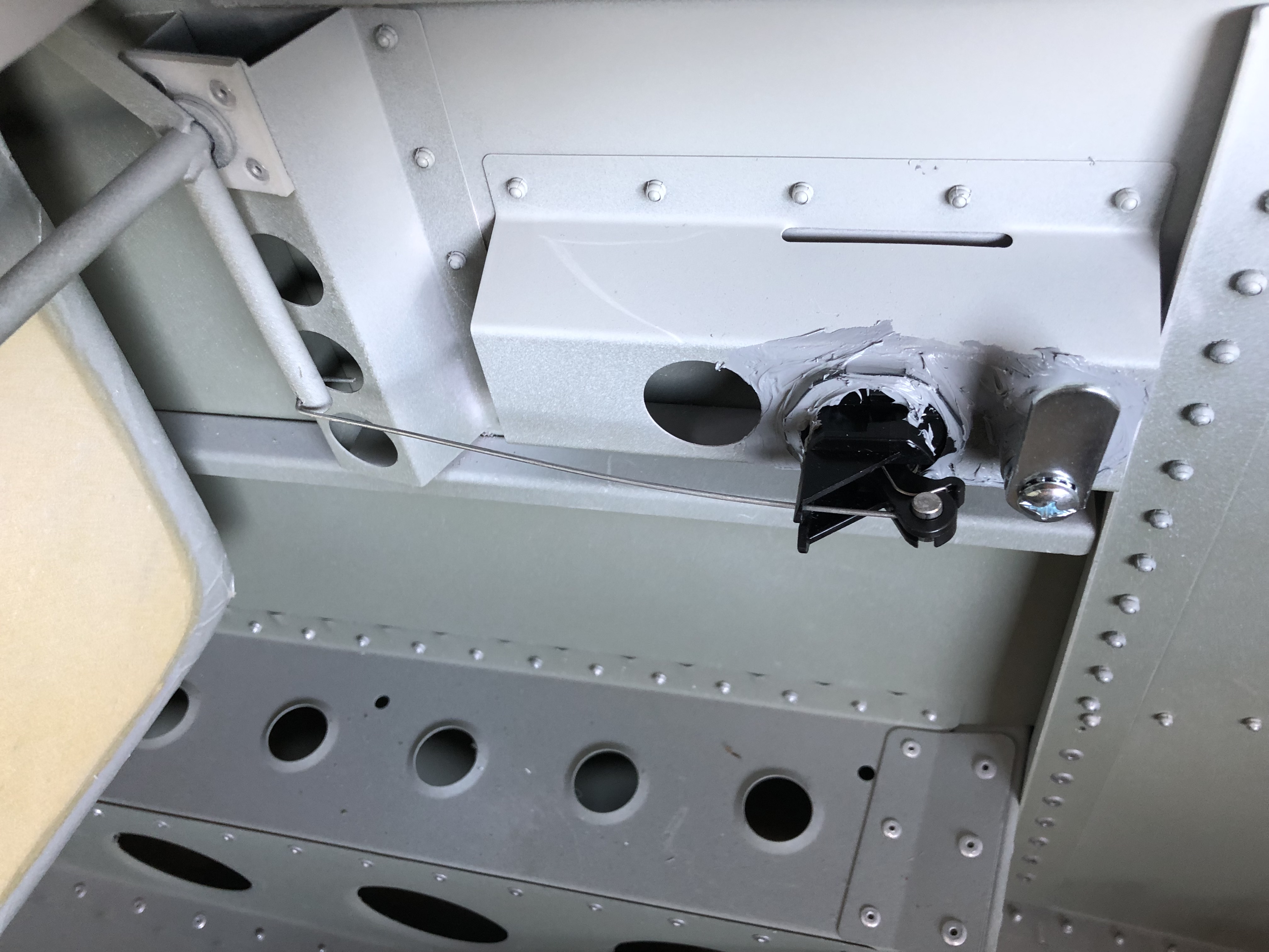
The actuating wire is cut to size and fed through the operating arm and finally the installation is sealed with silicone sealer.
Following the build of my Bristell NG5 Kit No. 382 Registration G-MLSY