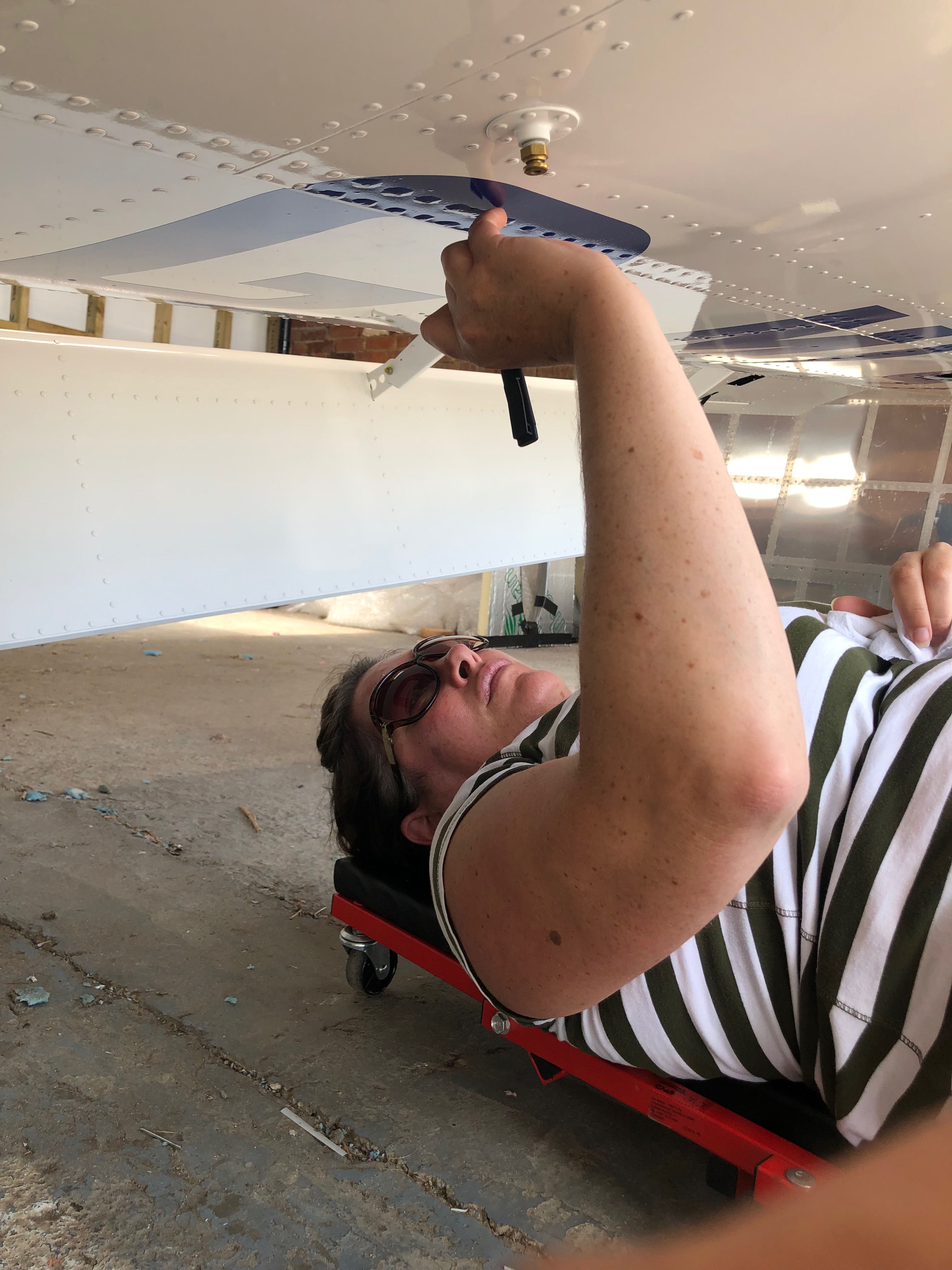
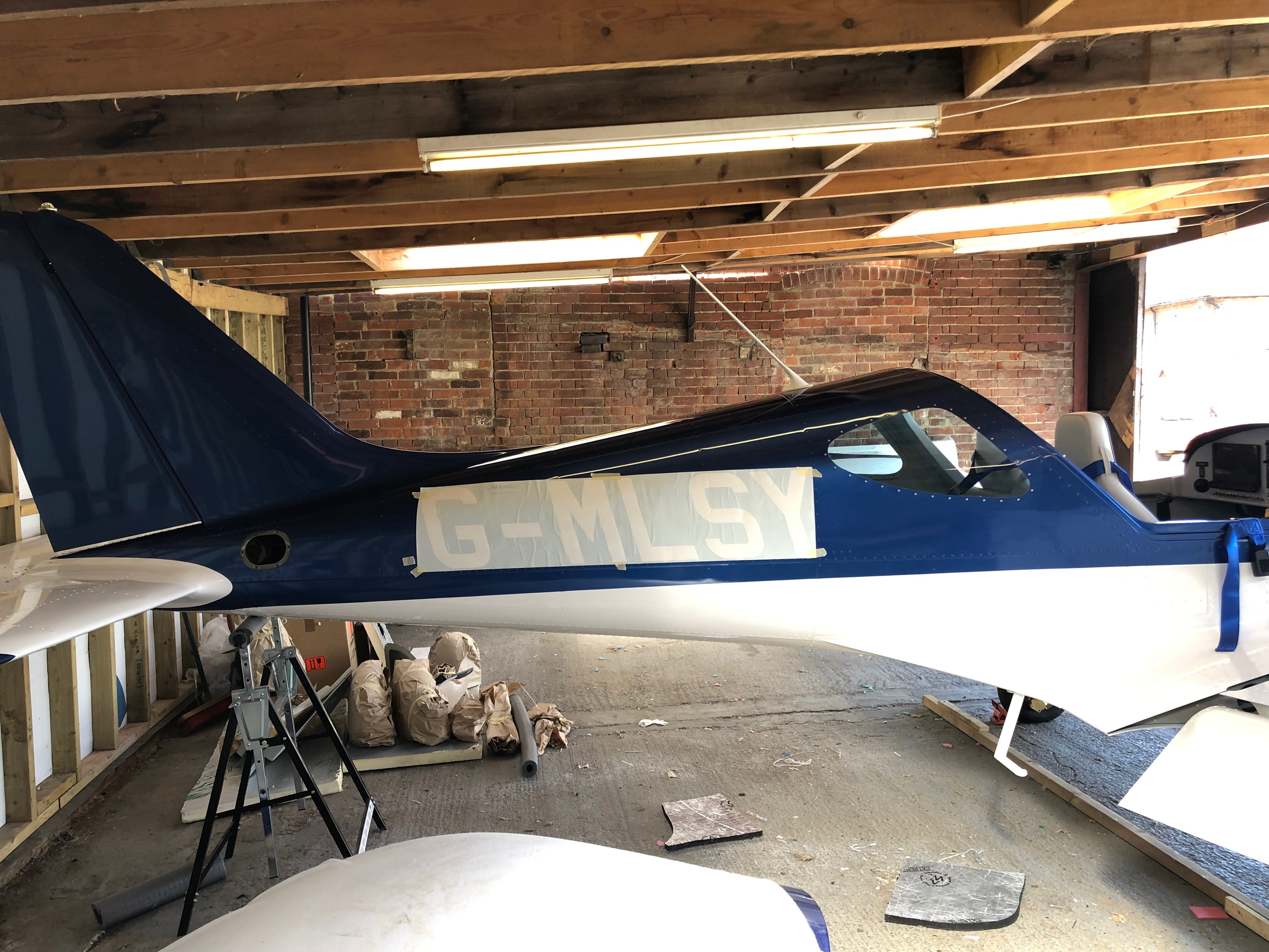
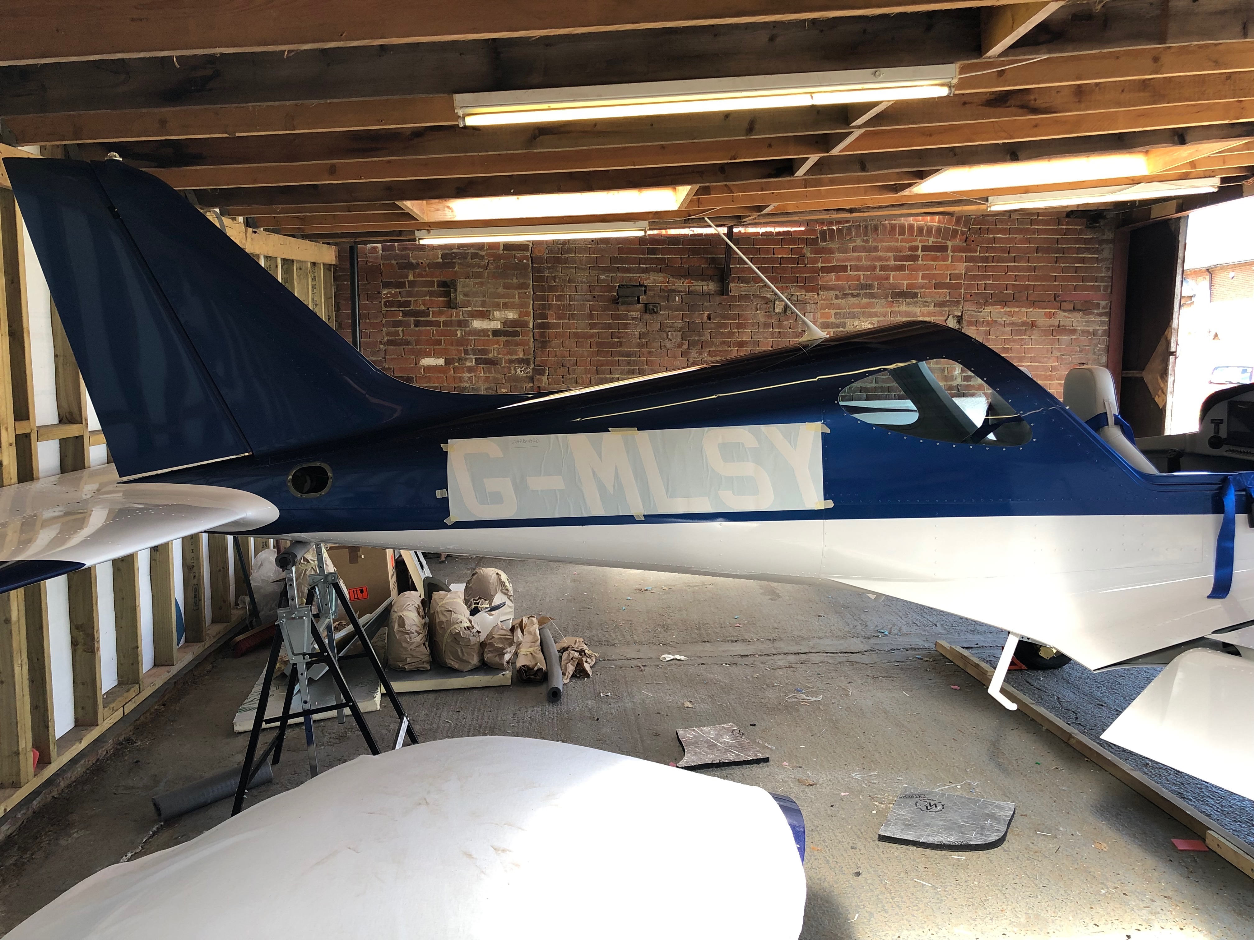
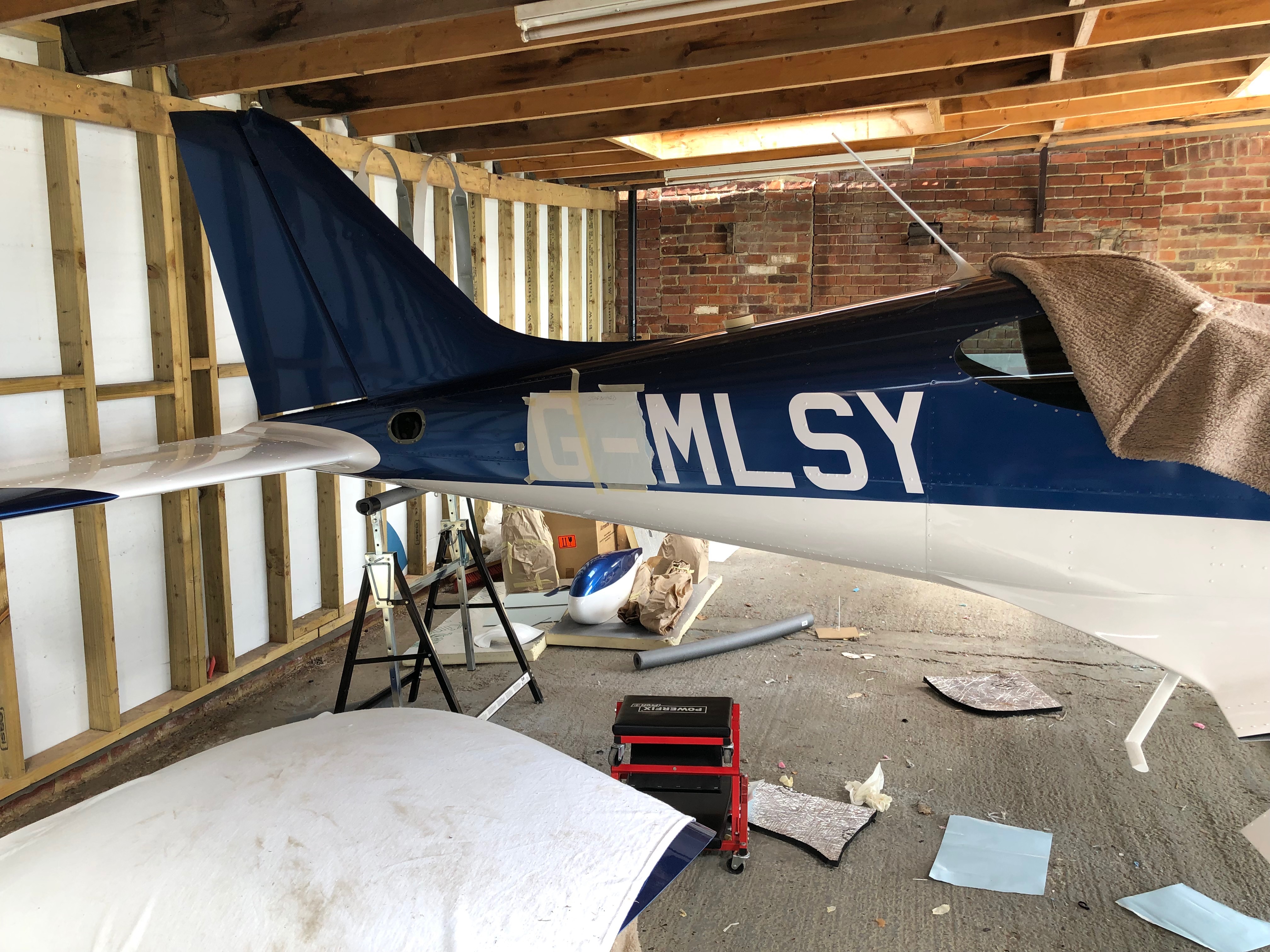
Karen came to the airfield today to help get rid of the little air bubbles around each of the rivets on the wing, did a sterling job as well. We tried several positions for the side registration to see which would look better. Pete Thomas, a friend from the London Gliding Club is coming down on Monday to do the weight and balance so I started to add all the bits and pieces that need to be on the aircraft from the weighing.
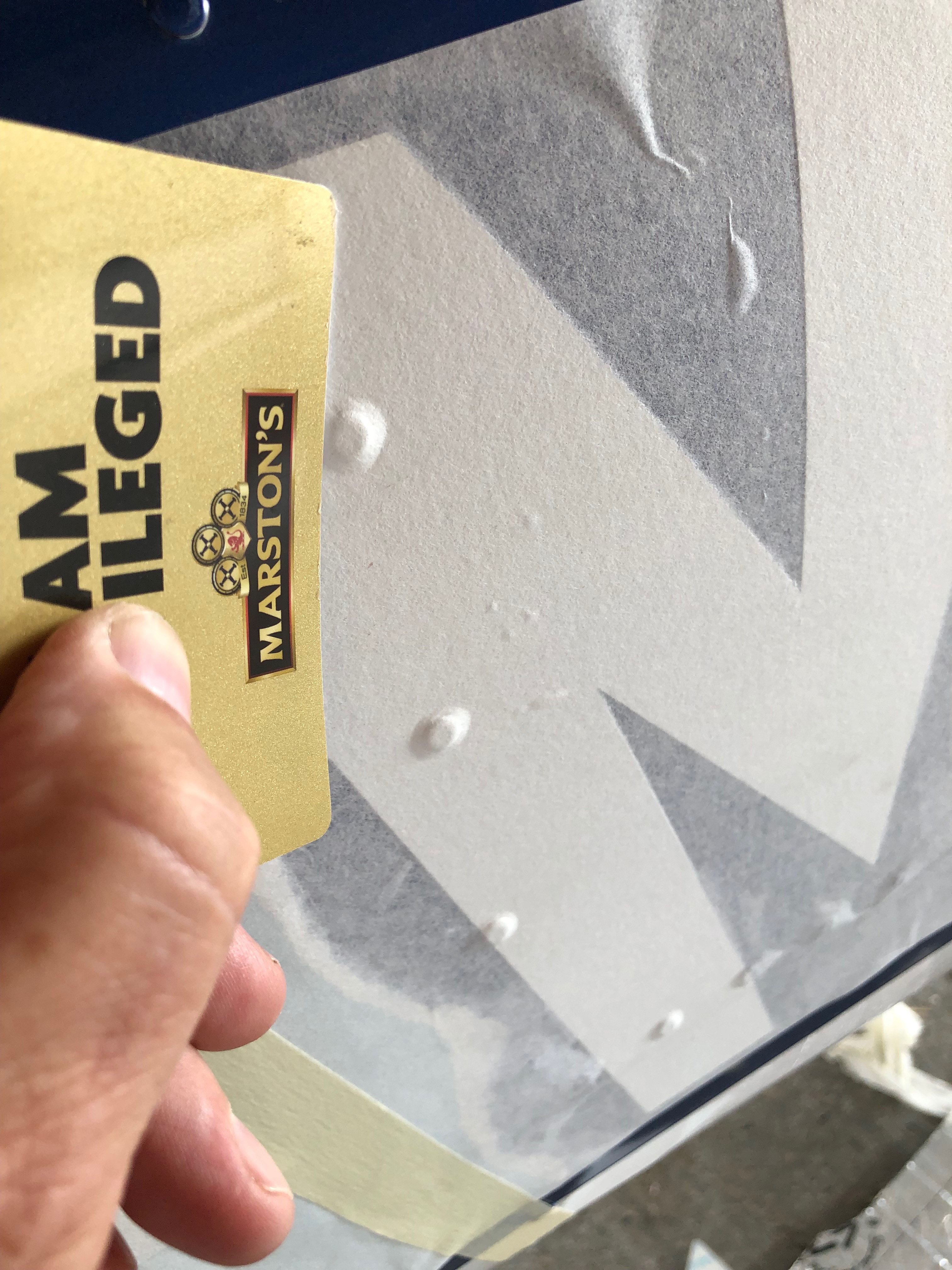
The vinyl registration doesn’t sit well around each rivet that it covers. A little air bubble is present on nearly every one of them. Karen used a fine point to pierce the vinyl and then gently pressed out the air. The result was fantastic and a big thanks to Karen giving up some her weekend to help me.Which looks better? aligning with the rivet line or ……the paint line. We both decided that the paint line was a better option so the decision is made.The spats need to go on as does the spinner and cowlings ready for weighing on Monday.Application of the registration starts. Not many pictures here on how to do it as I was worried about mucking it up.Part way though and it’s looking good. The next bit is to take a little of the spacing out between the ‘G’, ‘-‘ and the ‘M’ as it’ll look a bit better. I should have asked Pete from Mirage Signs to do that for me but I forgot!The final look. Very pleased with the result.A picture shows the inside of G-MLSY with all the seats and trim in place and a very happy me!
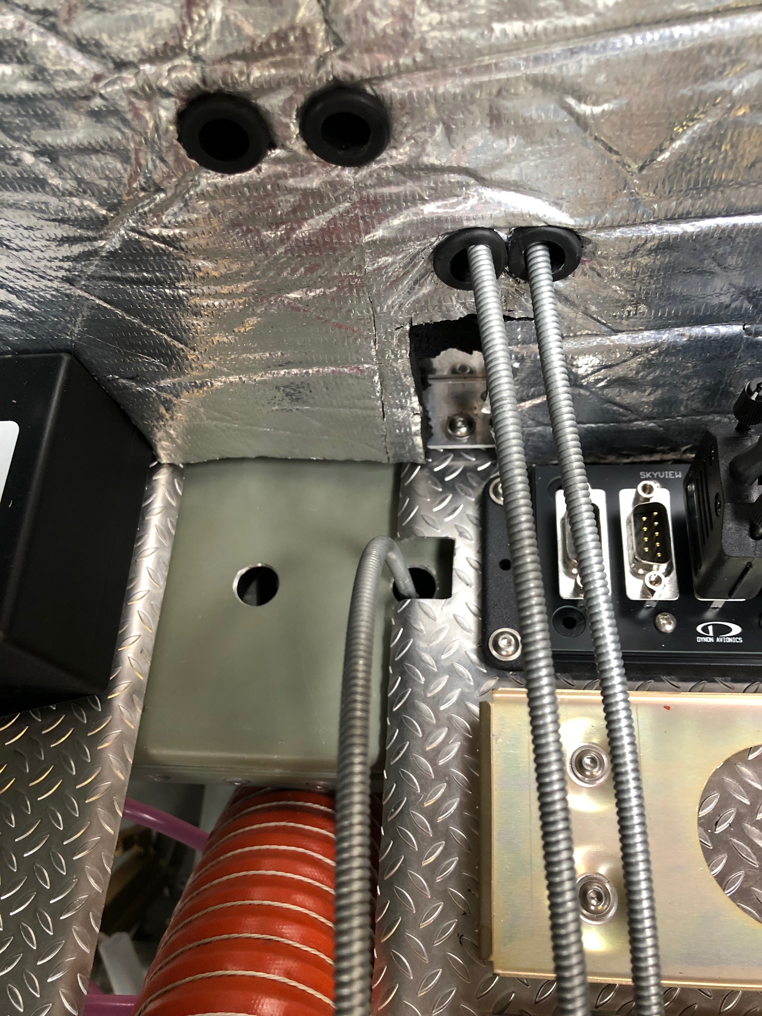
Short day today so just a couple of items. The first thing for today was setting the trim speed so it falls within the acceptable stop to stop time limits for the LAA followed by fitting the fuel pipe between the wing tanks and fuselage and finishing off by driving the holes for the LEMO plugs for the Bose headsets and fitting the rear trim panel. Also called CFS to see if my floats for the Rotax engine need changing as there has been a fault that’s been affecting them for 5 years now. You’d think they’d have sorted it out by now eh?
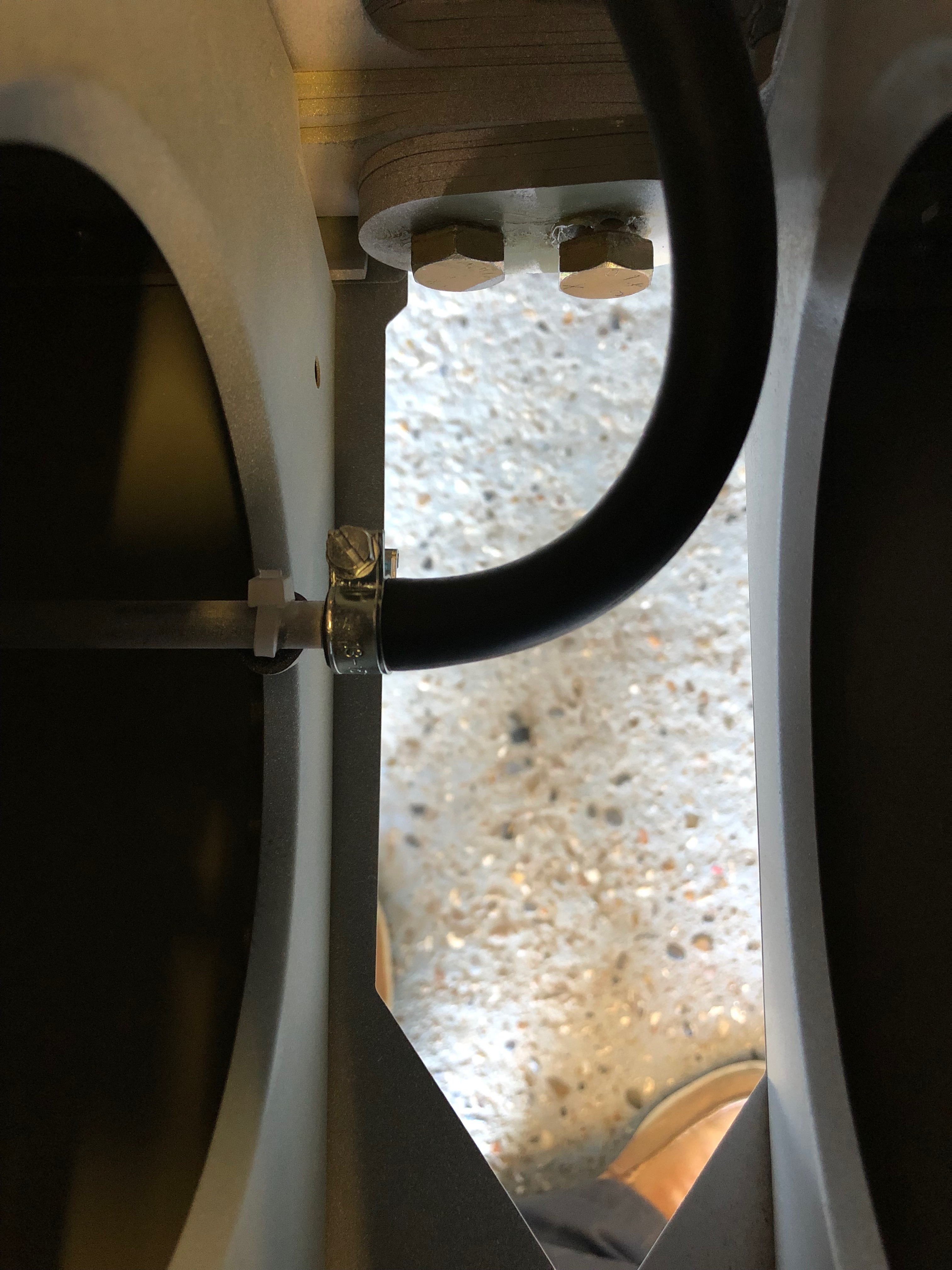
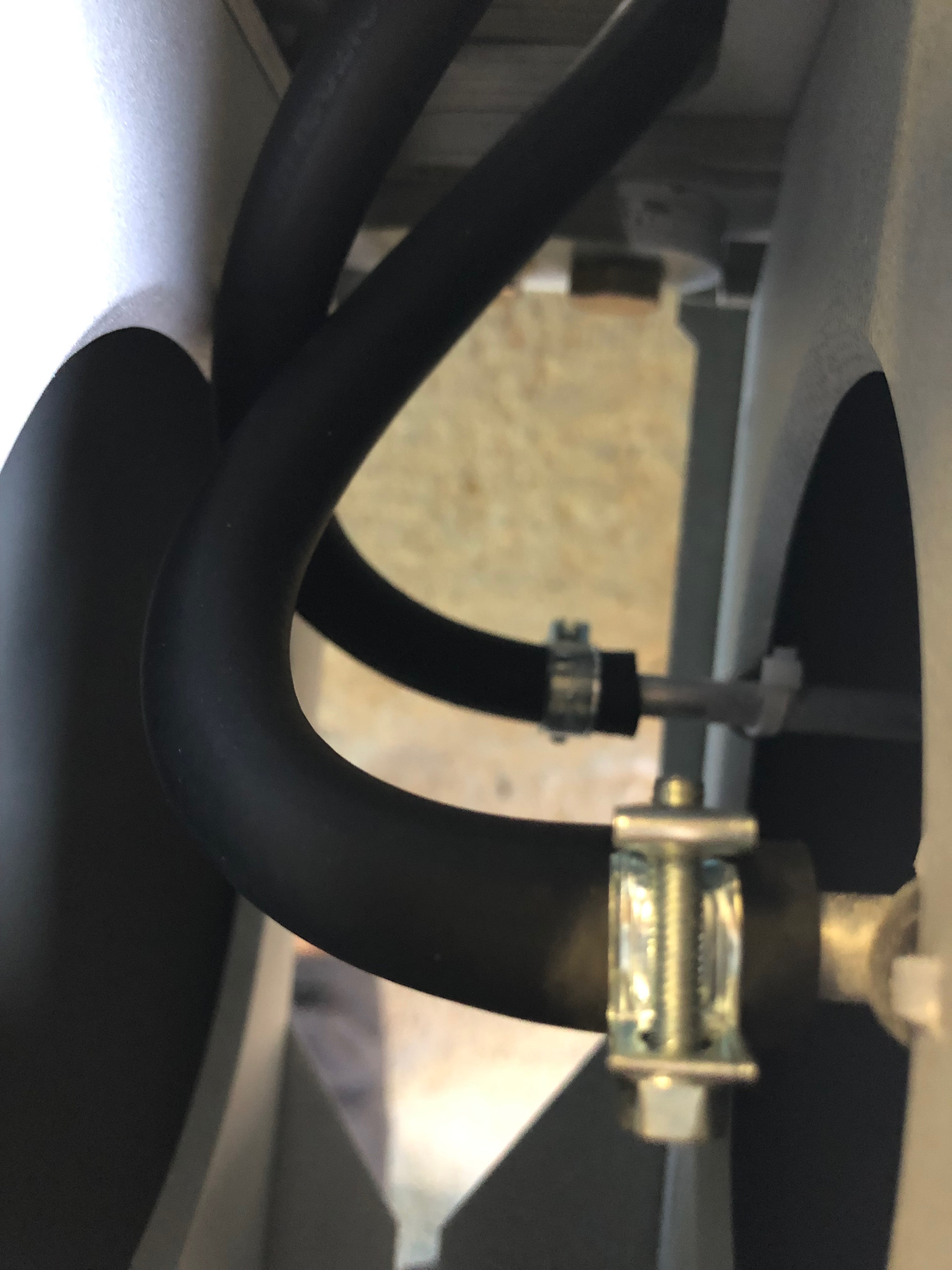
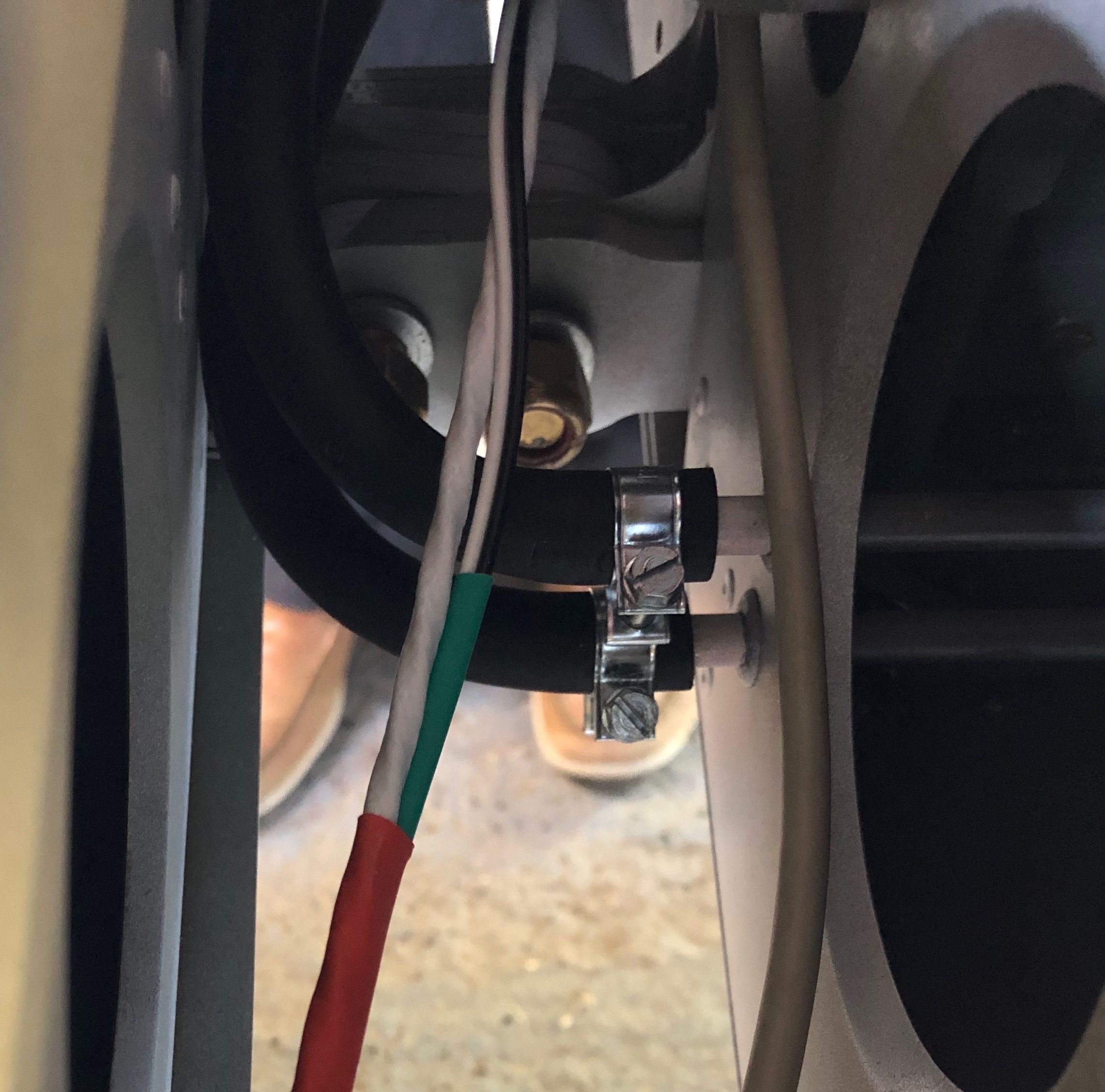
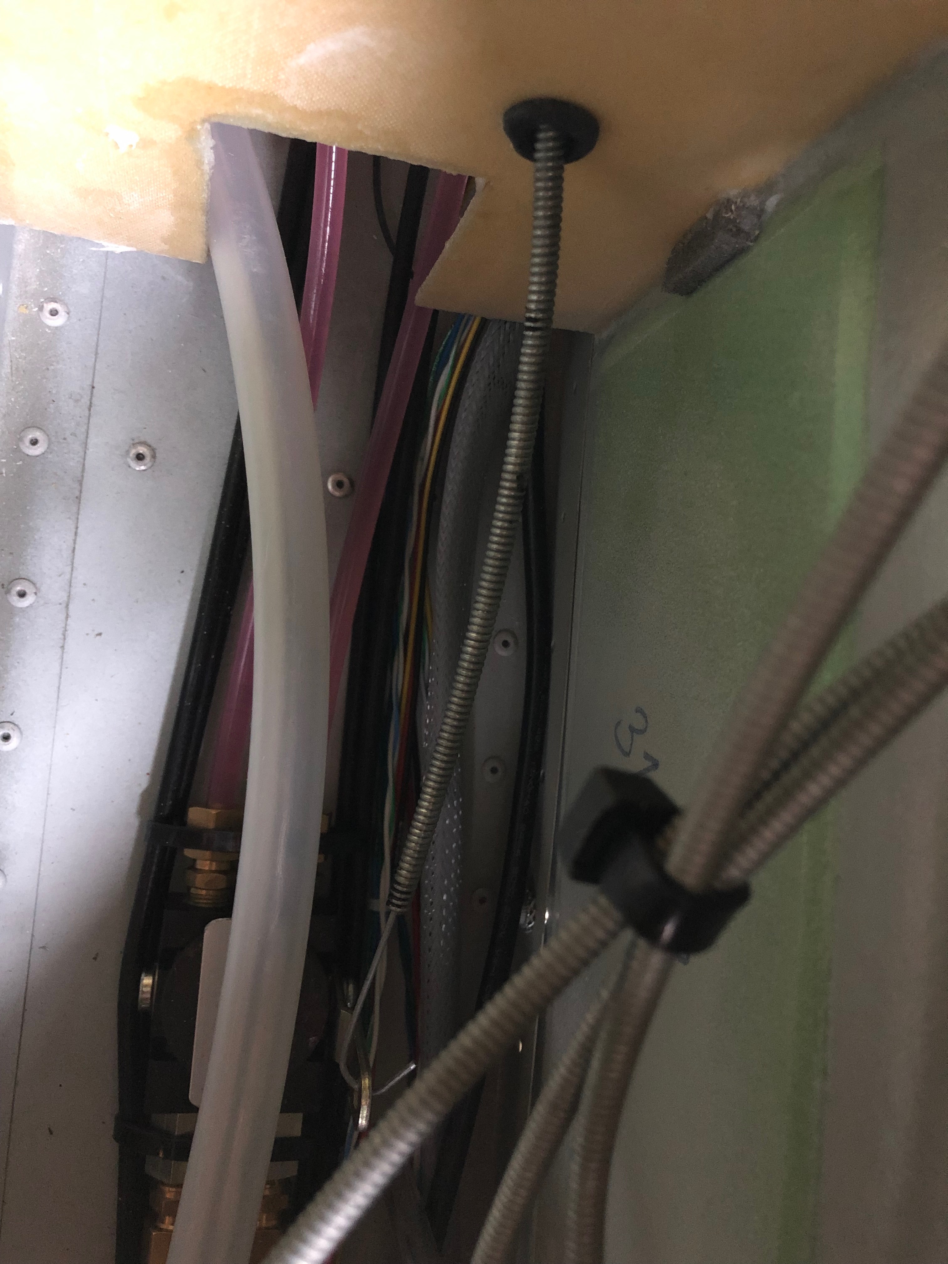
The starboard wing has a single pipe that runs from the fuel tank in the wing to the fuselage. It’s quite a tight fit so need to make sure it doesn’t kink and it’ll need protecting with some sheathing.The Port wing fuel tank has two pipes one for supply and one for return. When starting the engine it’s important to select the Port fuel tank as any surplus fuel is returned to that tank. If it’s already full it will overflow. Must make sure you don’t get the supply and return mixed up!The feed and return pipes from the fuselage. The bottom one is the return.I’ve already fitted the centre canopy release mechanism so all that is required is to drill and shape the two holes for the LEMO headset sockets. They fit from underneath so they can be fitted with the sockets already attached.Last job of the day is to fit the rear trim panel. I decided to make the panel removable so Rivnuts and screws are used to secure.
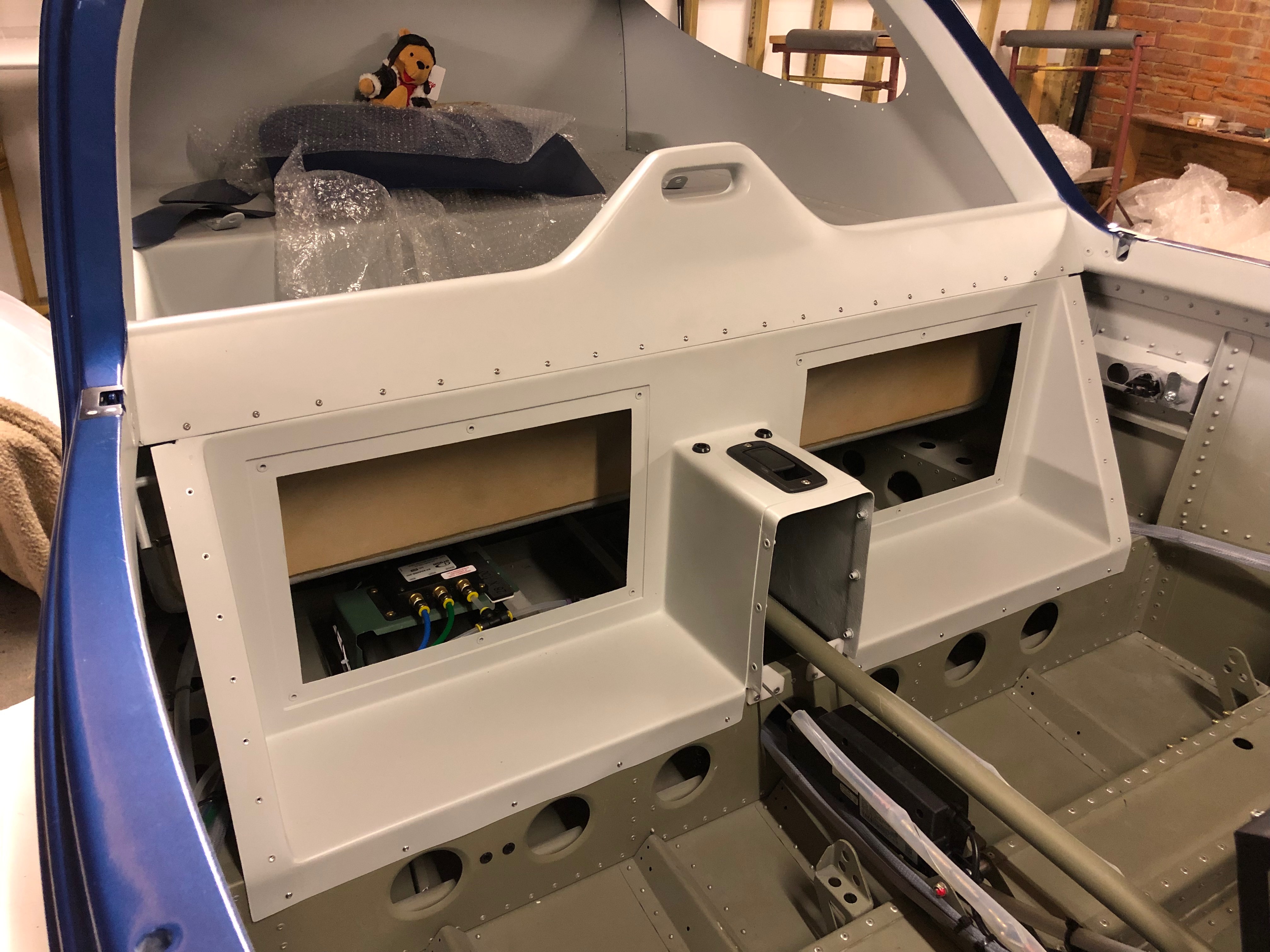
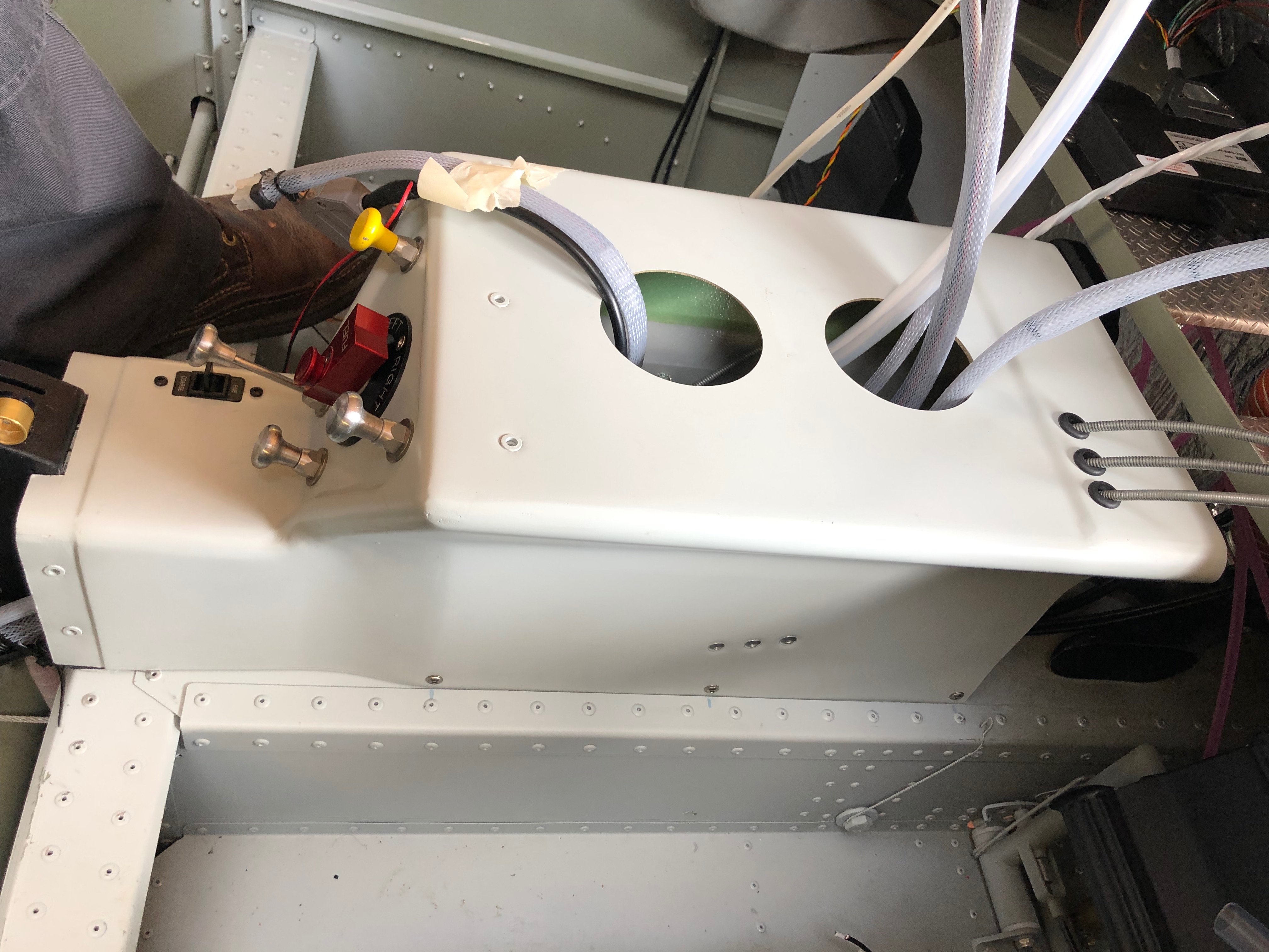
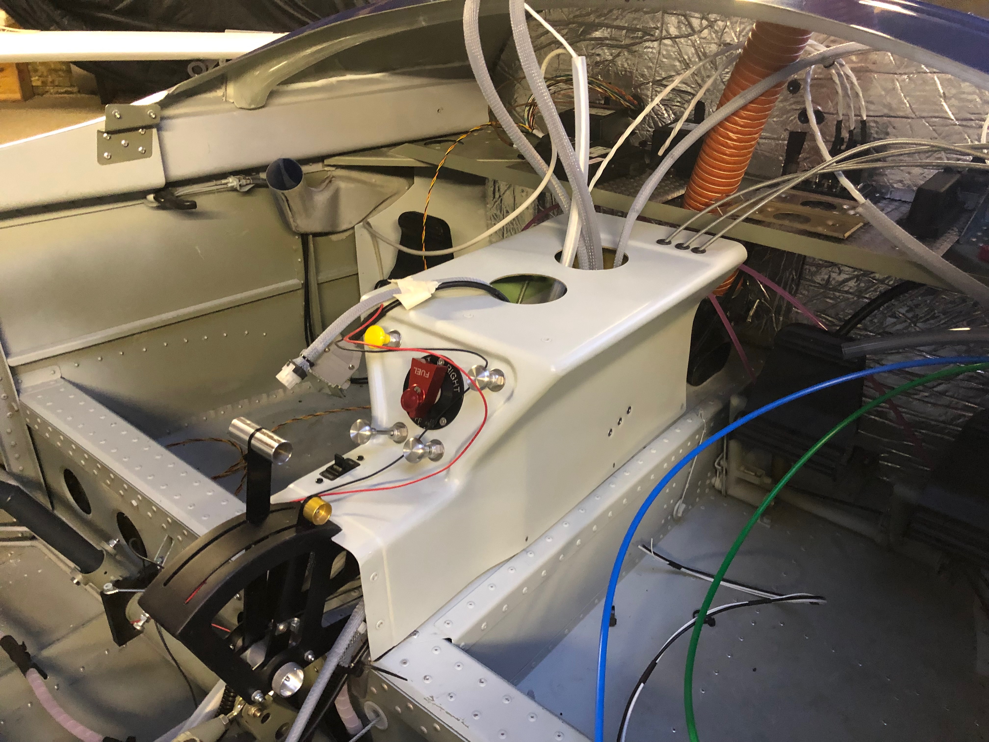
With all the prep to fit the centre console, today’s the day to fit it for the final time. All the control cable outers have been routed and cut, the connections worked out, the pipe runs decided on and checked. Now it’s just a case of carrying out the fit.
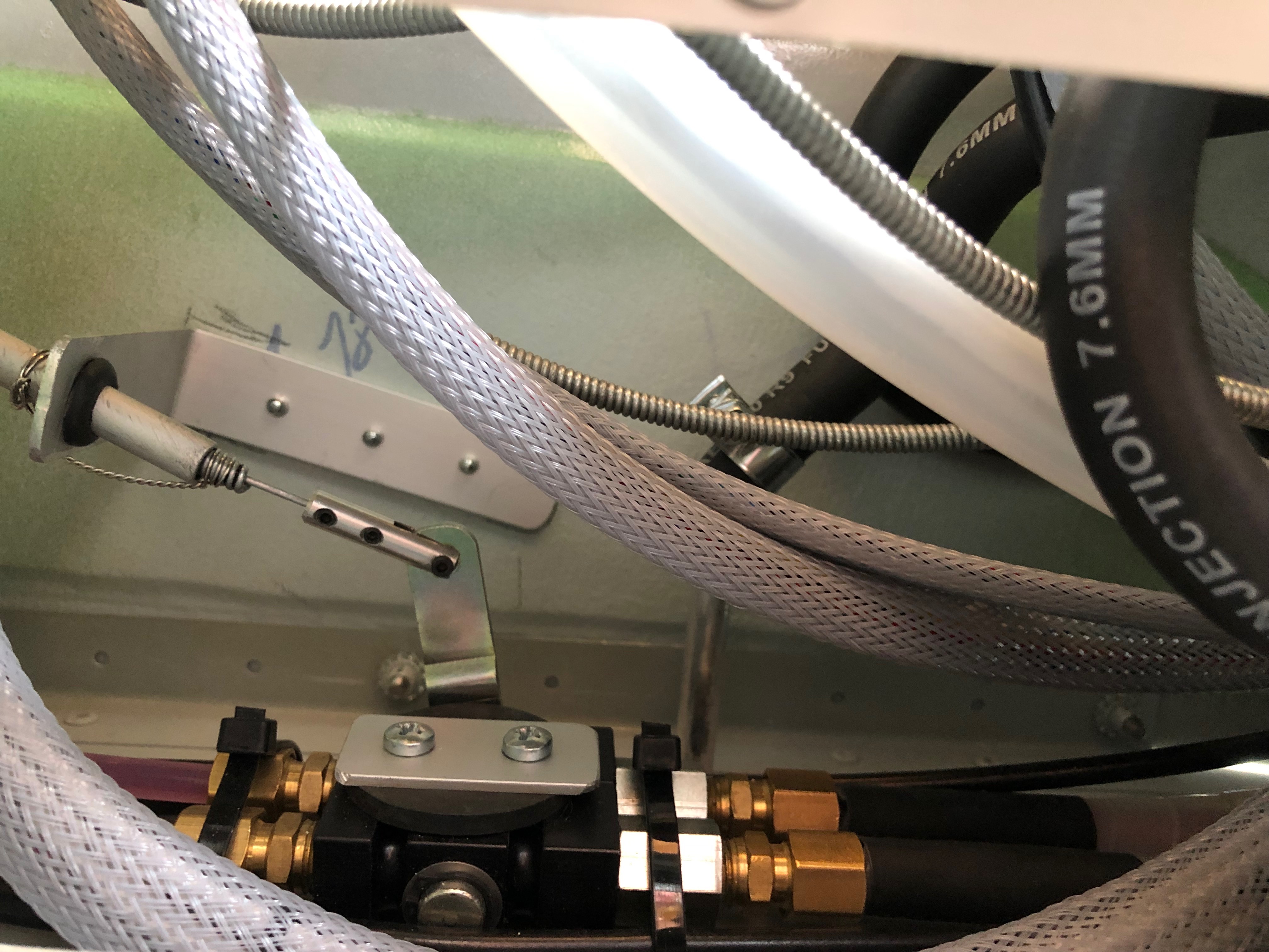
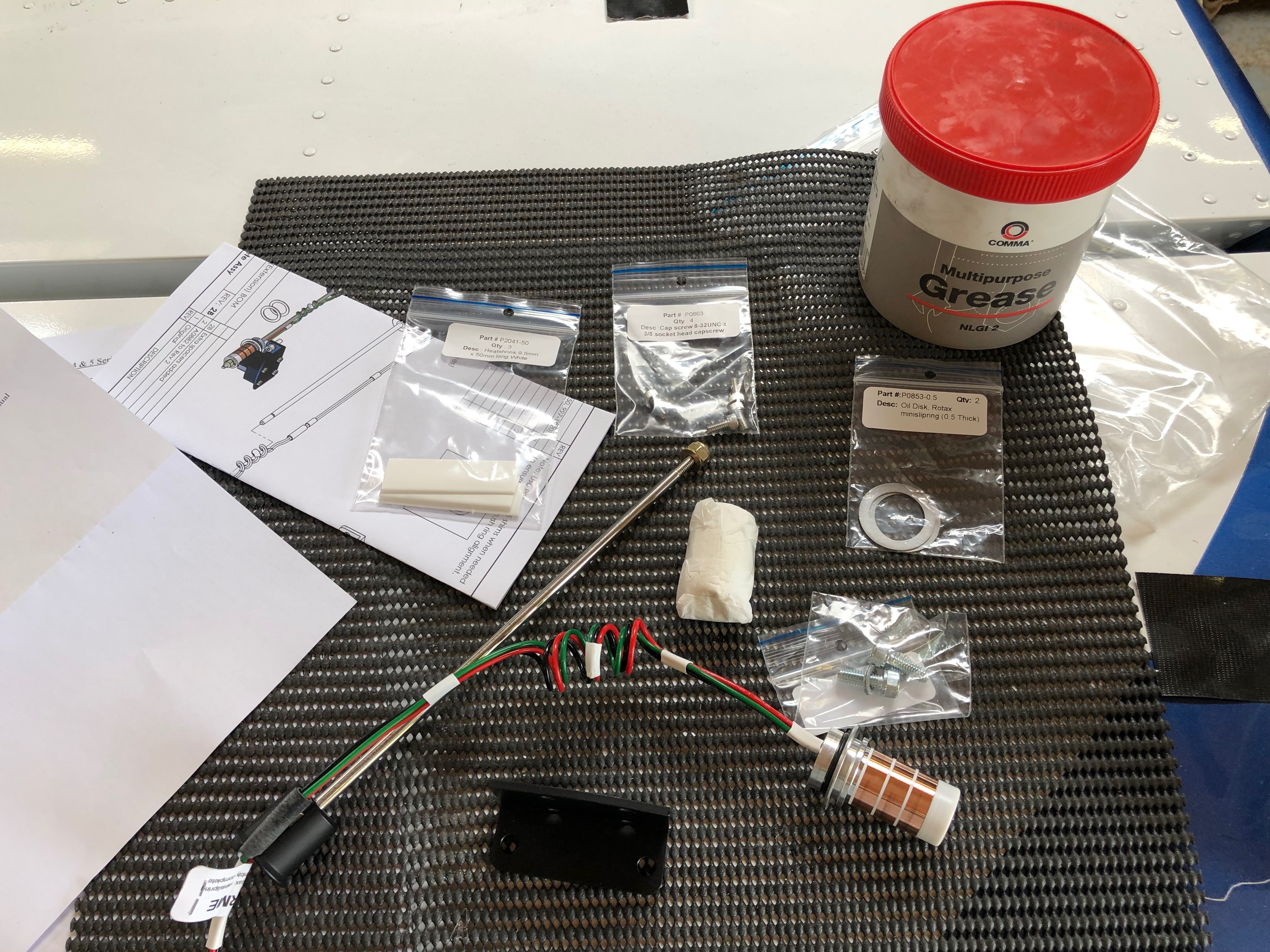
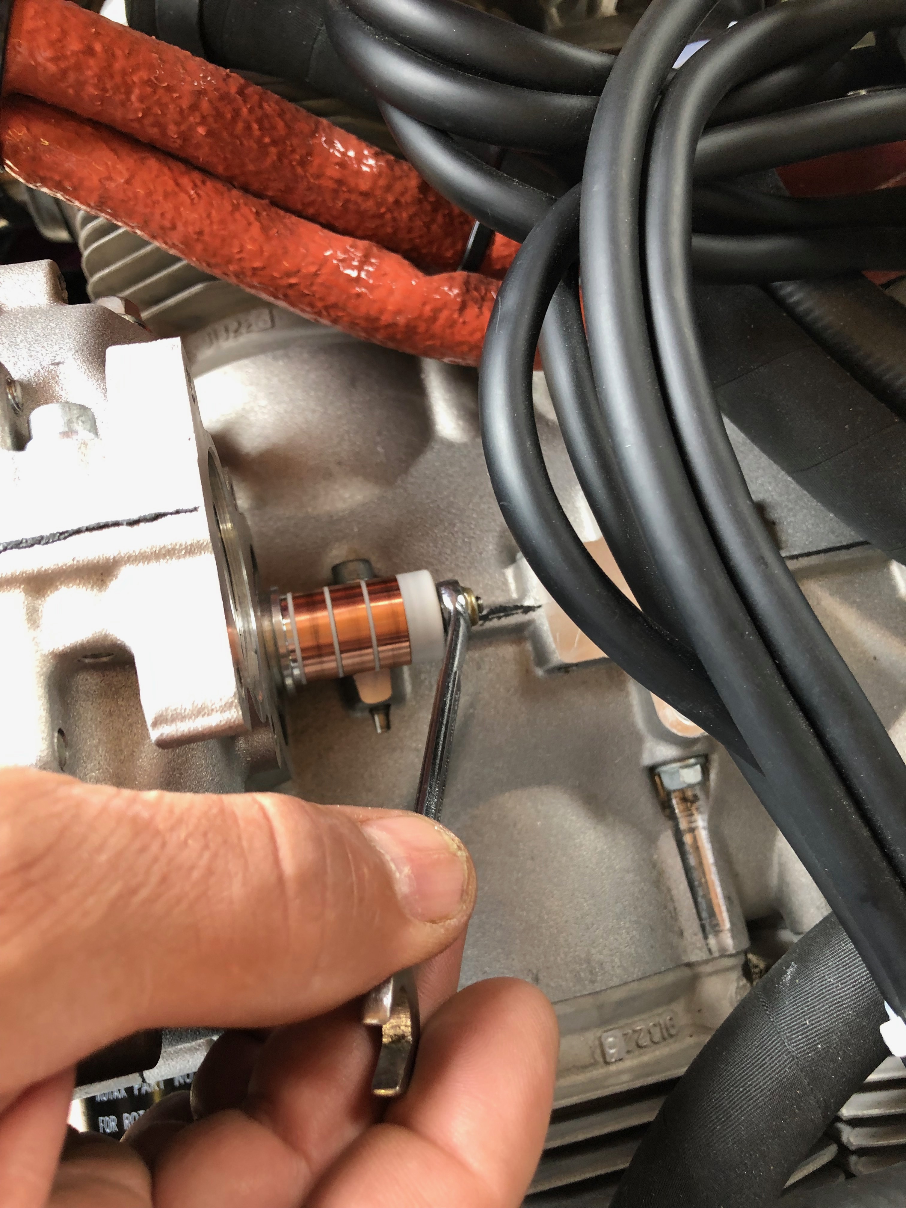
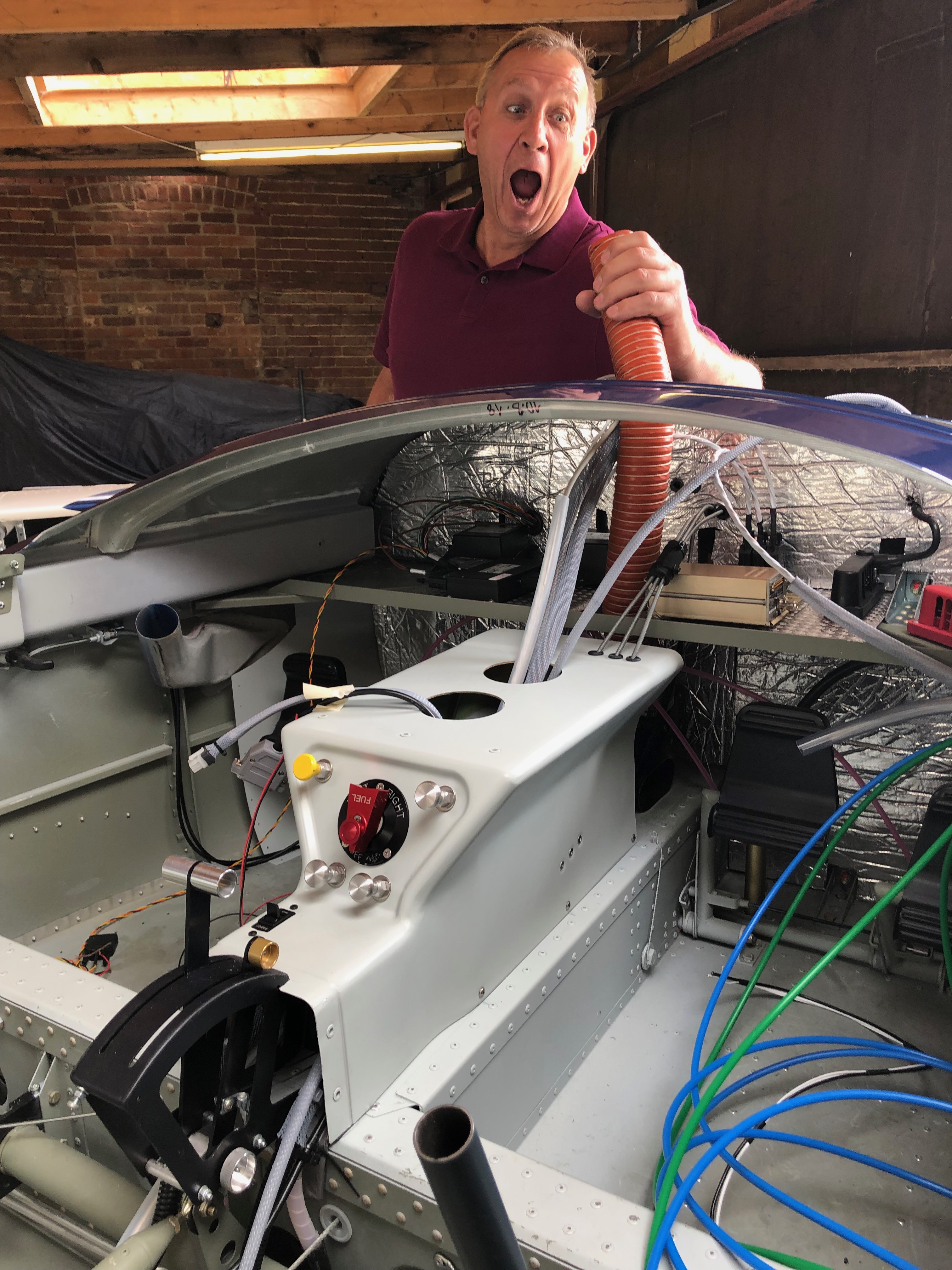
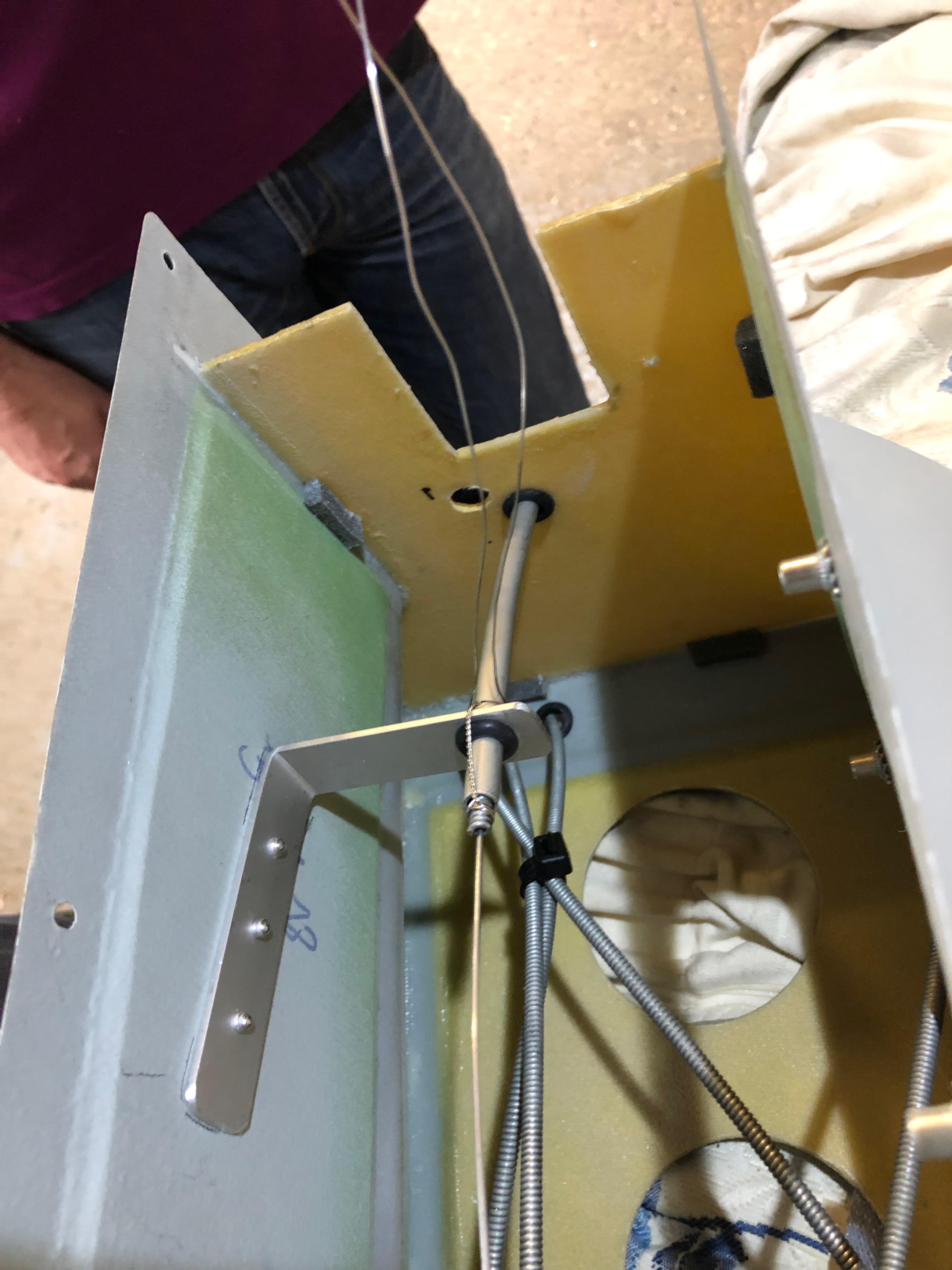
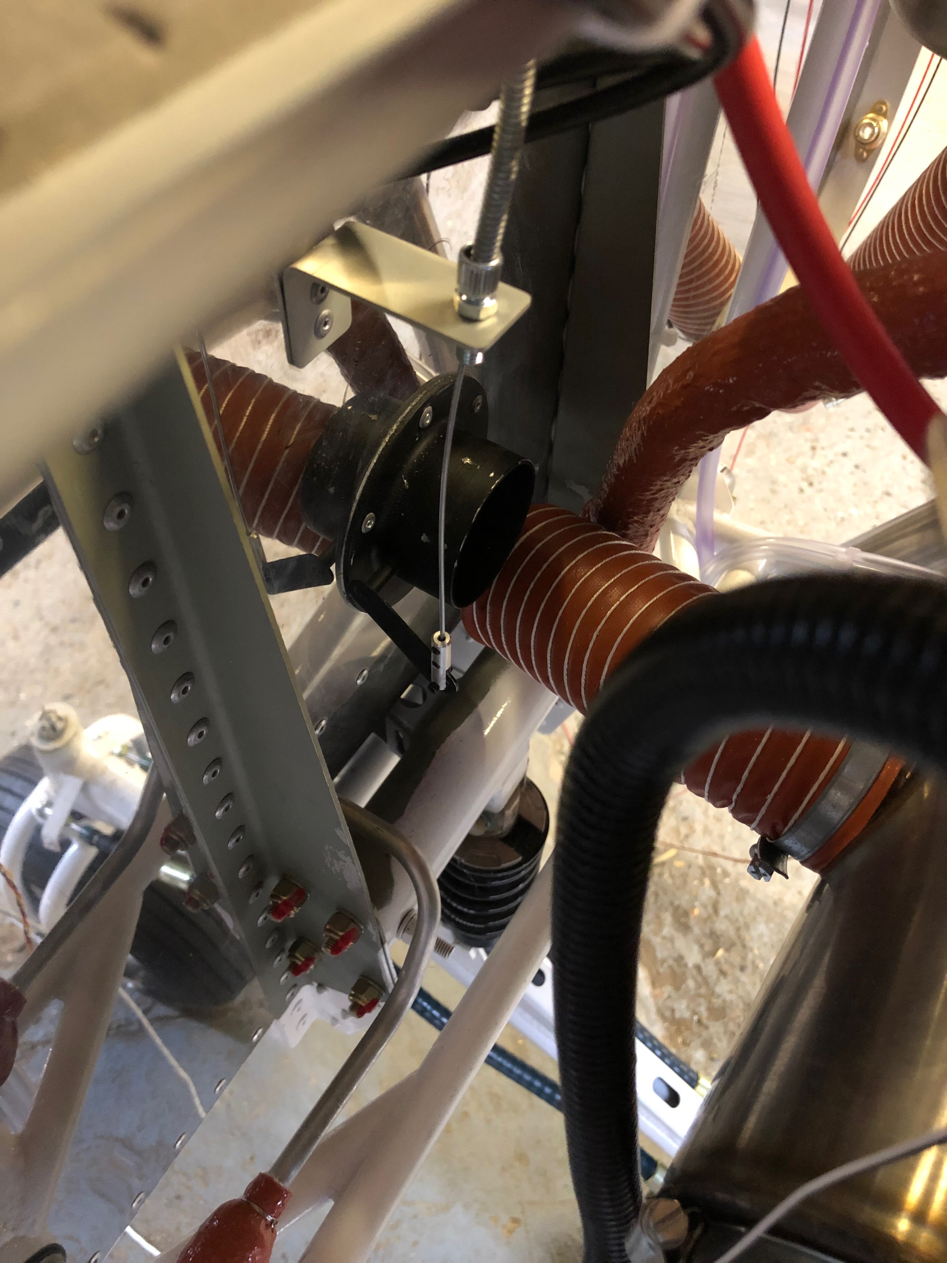
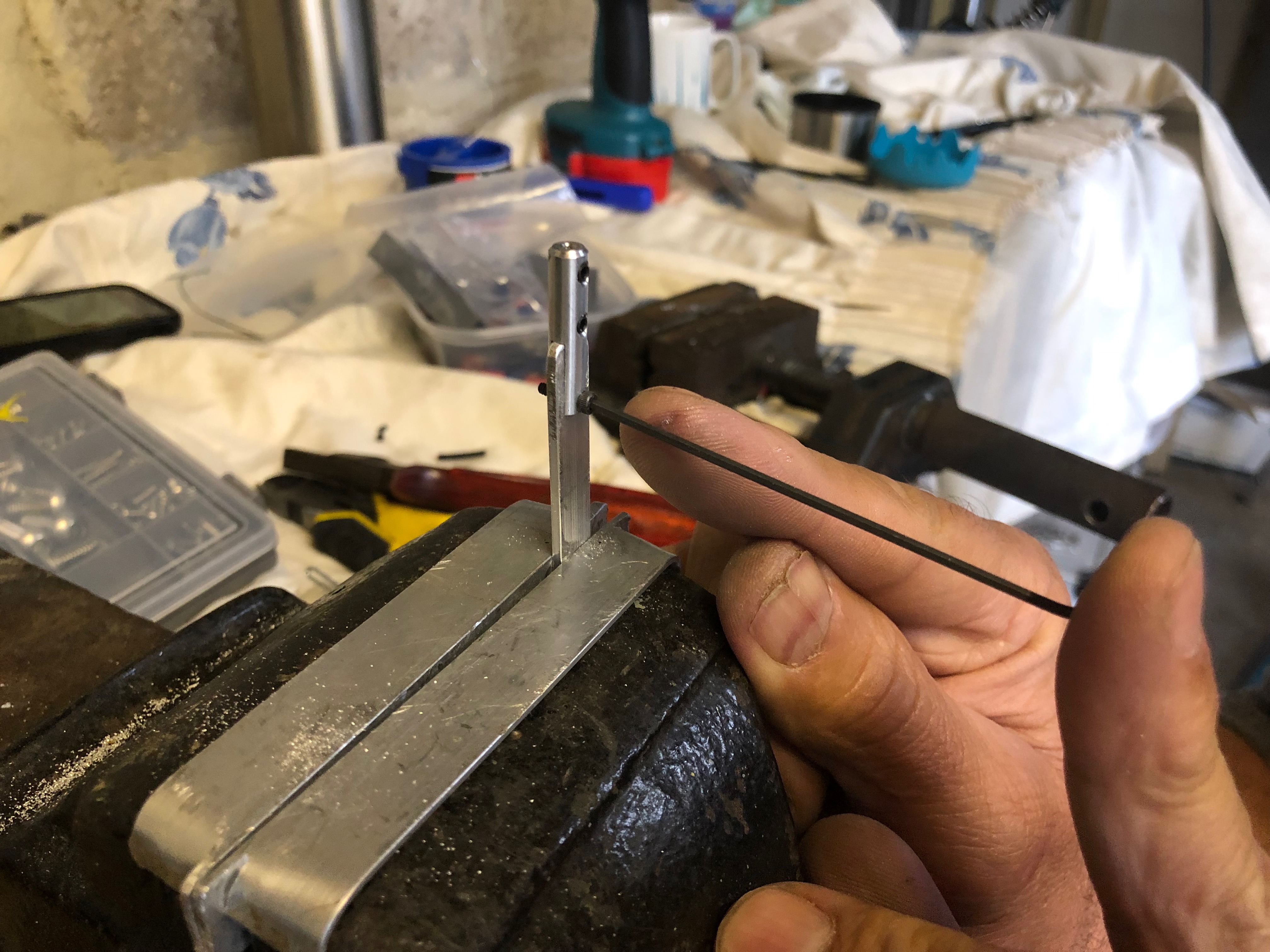
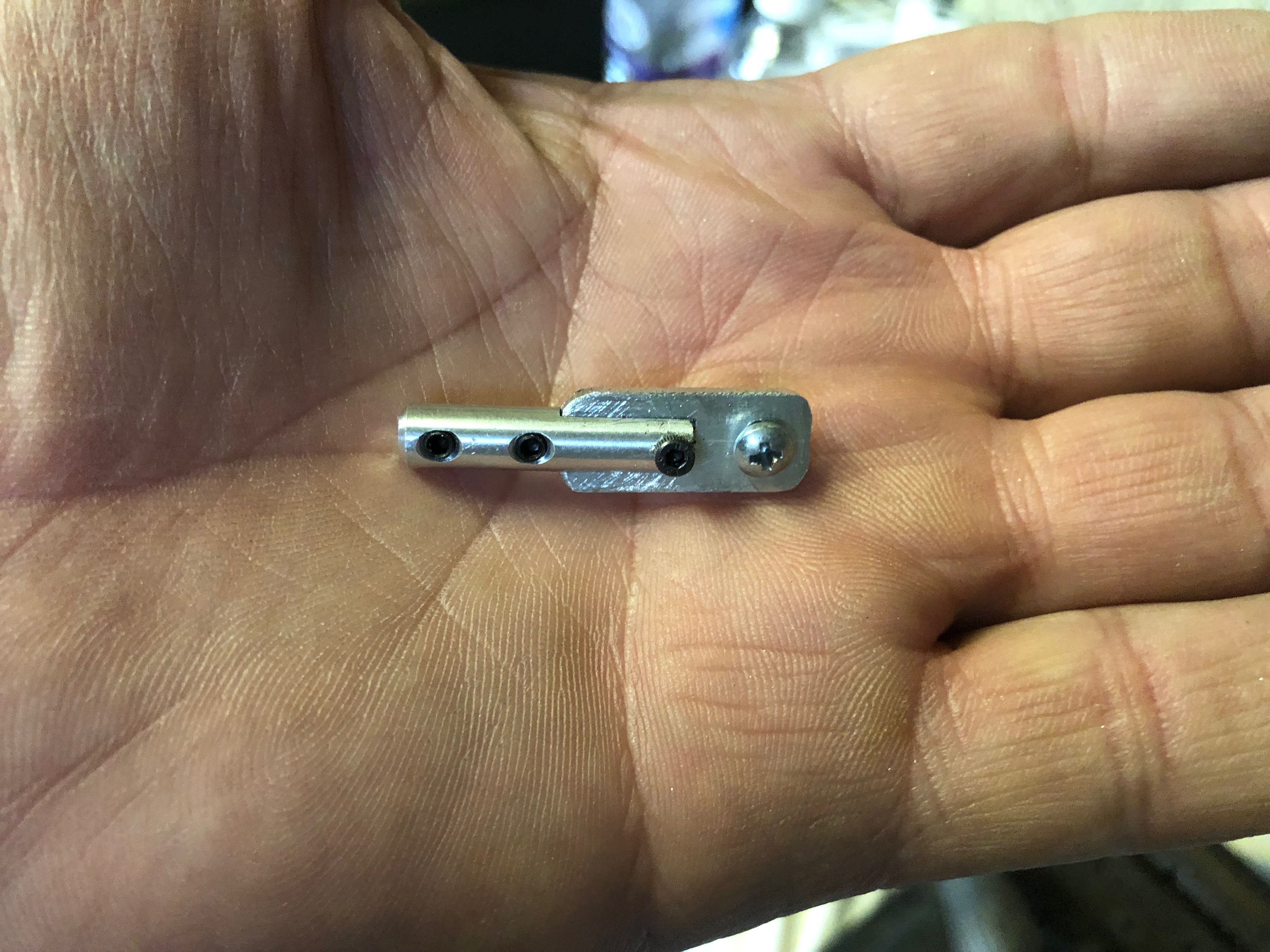
The fuel pipe from the selector to the tanks and engine need to be routed so they don’t kink and cut the supply whilst also being kept away from anything that may chaff them.This shows the support bracket for the park brake cable. It works well.The outer cables are wire locked to the adjusters so they can’t move once fitted.The demist control with the connector we made up. It looks a very good solution.At last the centre console’s complete with all the controls fitted, cables run and fuel pipes fitted. Having received the prop on Monday I can start to install the various bits. This is the mini slip ring available for Rotax 912ULS type 2 engines. It’s fitted to the rear of the gearbox.and then secured in place with a rod hat runs through the hollow gearbox shaft. The control wires spiral round the rod… and exit the front of the engine ready for connection to the pitch motor wires in the spinner.Once the slip ring is fitted the pick up bushes are installed. The bushes need run centrally on the slip ring. That’s all for the prop today, more tomorrow.Moving on to the panel again. I will fit as much as possible before fitting to the aircraft as it’s a lot easier than fitting the components when the instrument panel has been fitted to the aircraft. I’m not sure what Tom is doing here? Perhaps he’s going to start to sing? Captions please! He’s going home today so I’m solo again tomorrow!
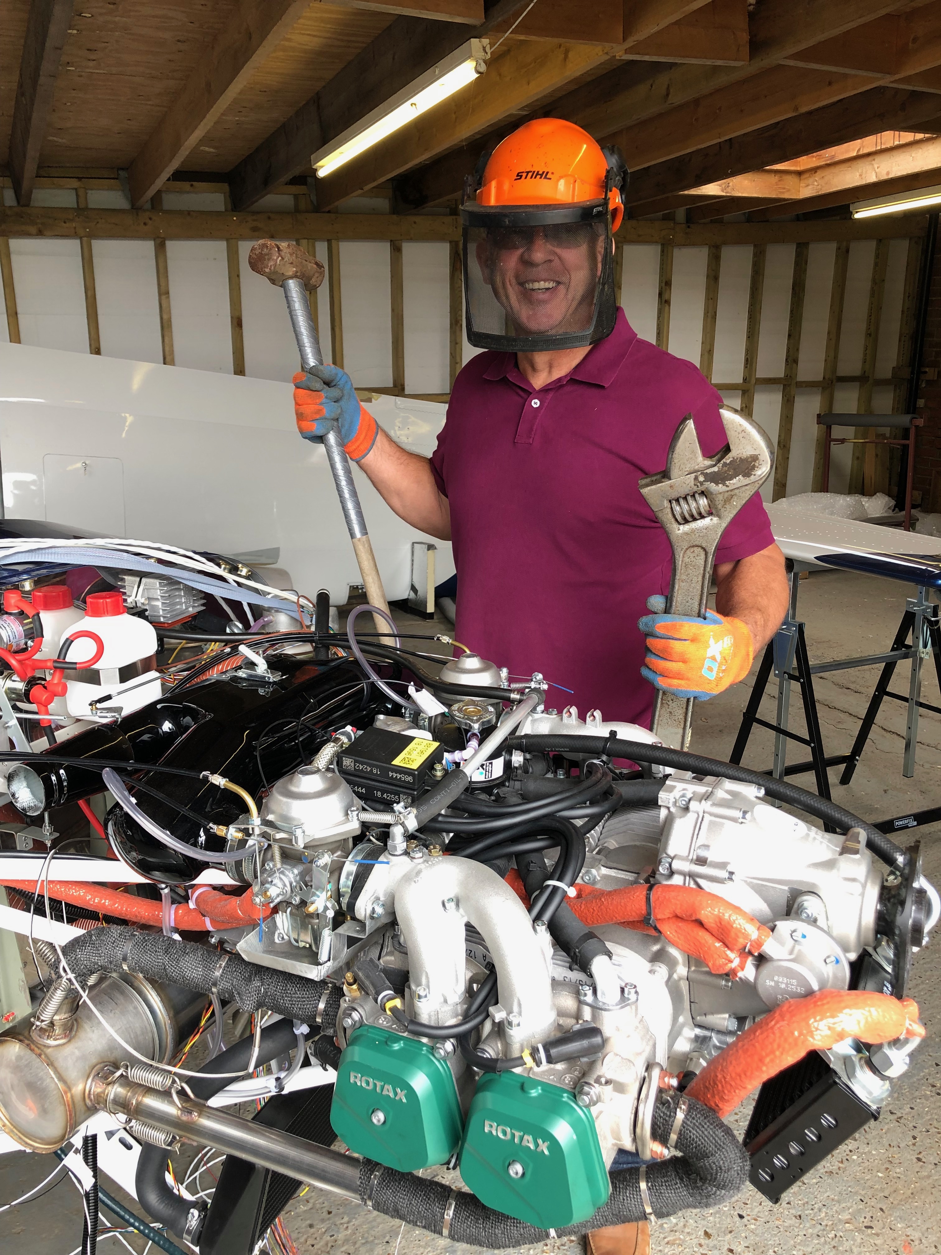
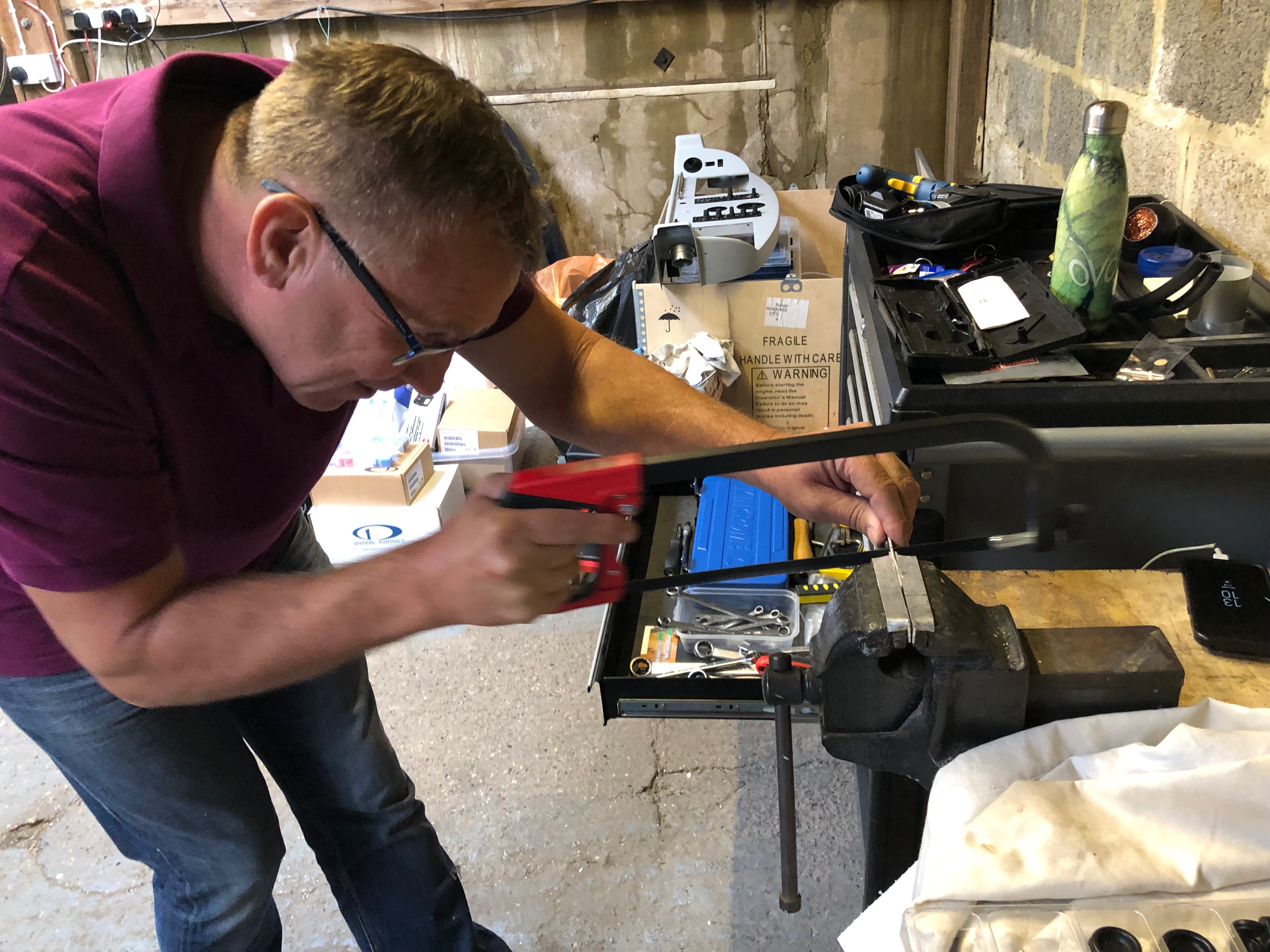
Tom came down to stay for a couple of days and give me a hand. Luckily he bought some tools with him from the land of the giants!
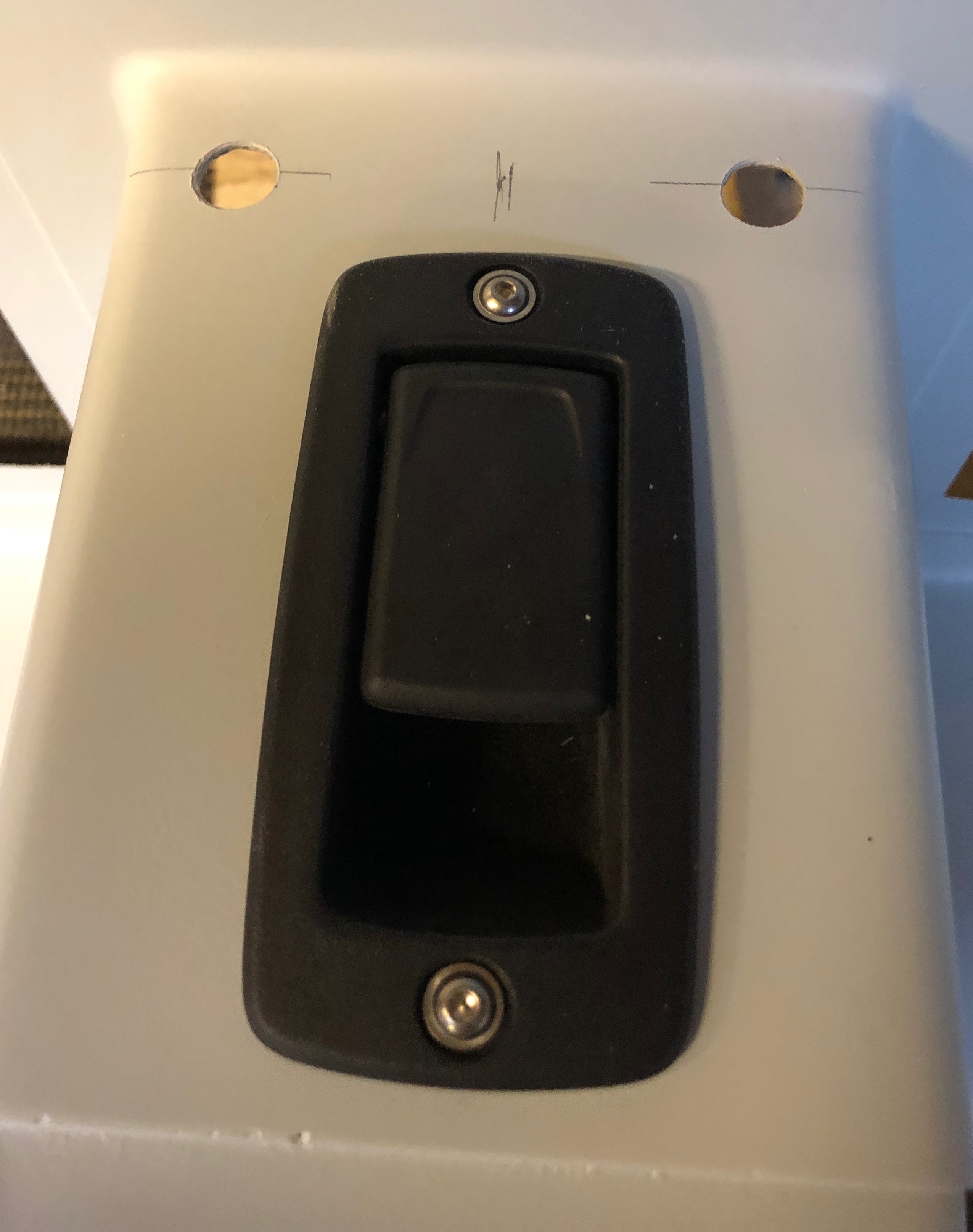
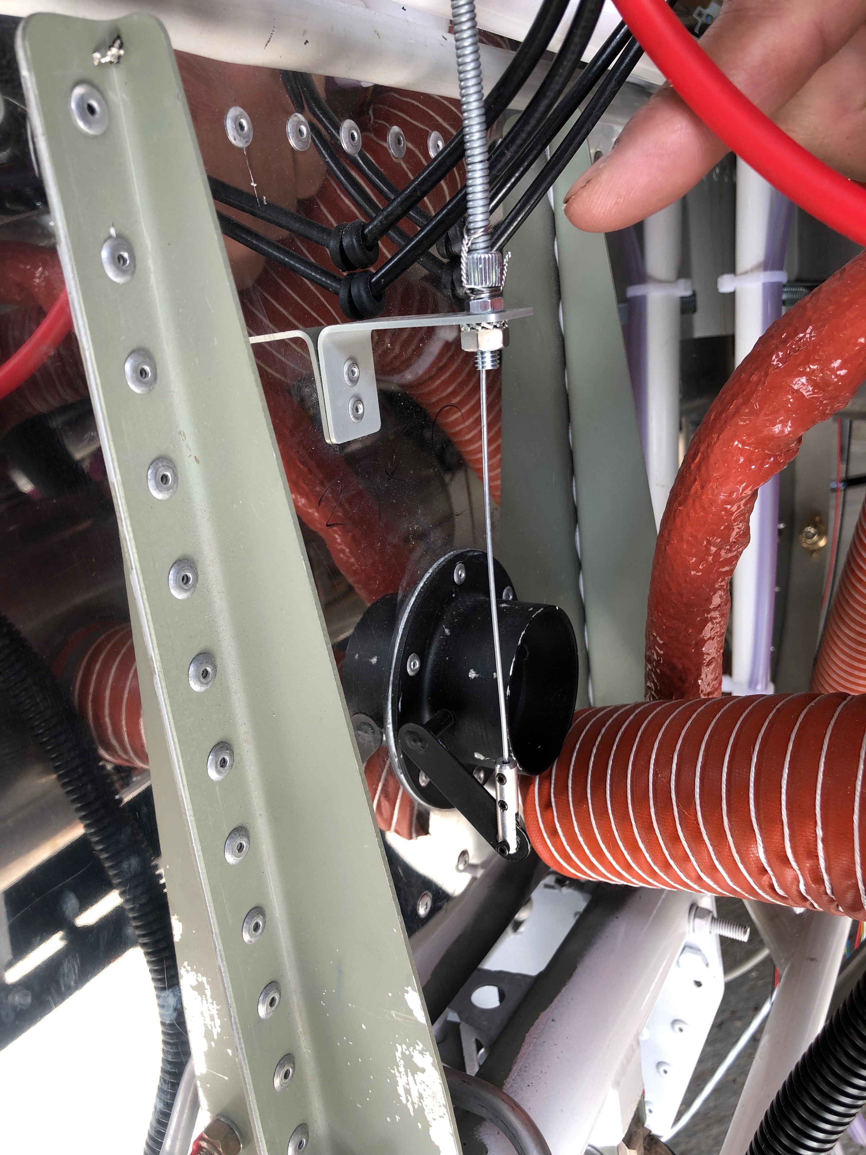
Today we were concentrating on fitting the centre console, ensuring that all the control operate smoothly for the carb heat, cabin heater and demister. The park brake needed some special attention as it needed to operate with push on and pull off. This required the cable to exit the front of the console and loop back in. This would make it operate in the correct source but there would be about 100mm of unsupported cable which would bend and it’s unlikely to operate correctly. The other connection that would need a bit of thought would be the connection to the demister as it had a protrusion to connect to and not a hole like the other controls.
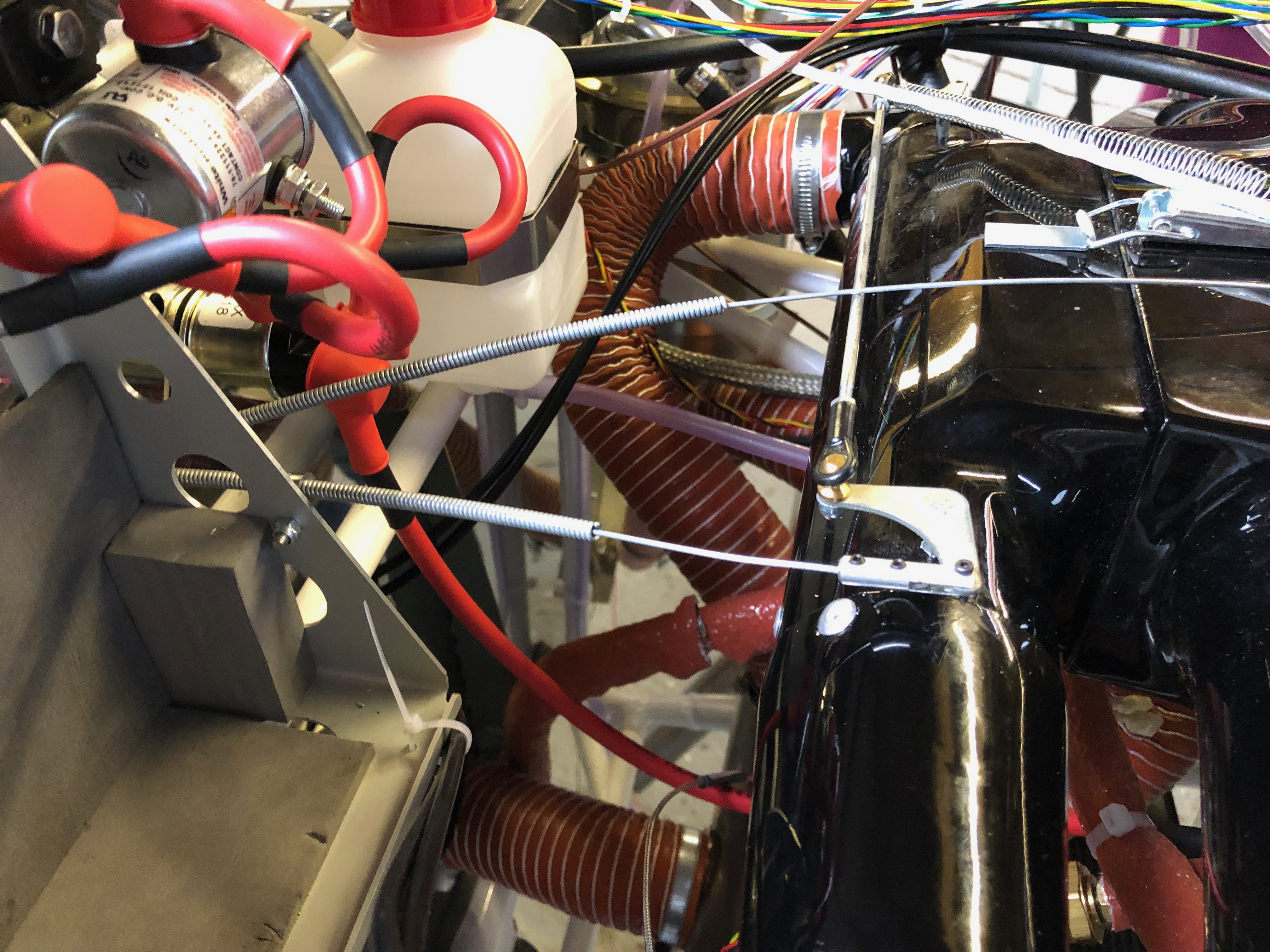
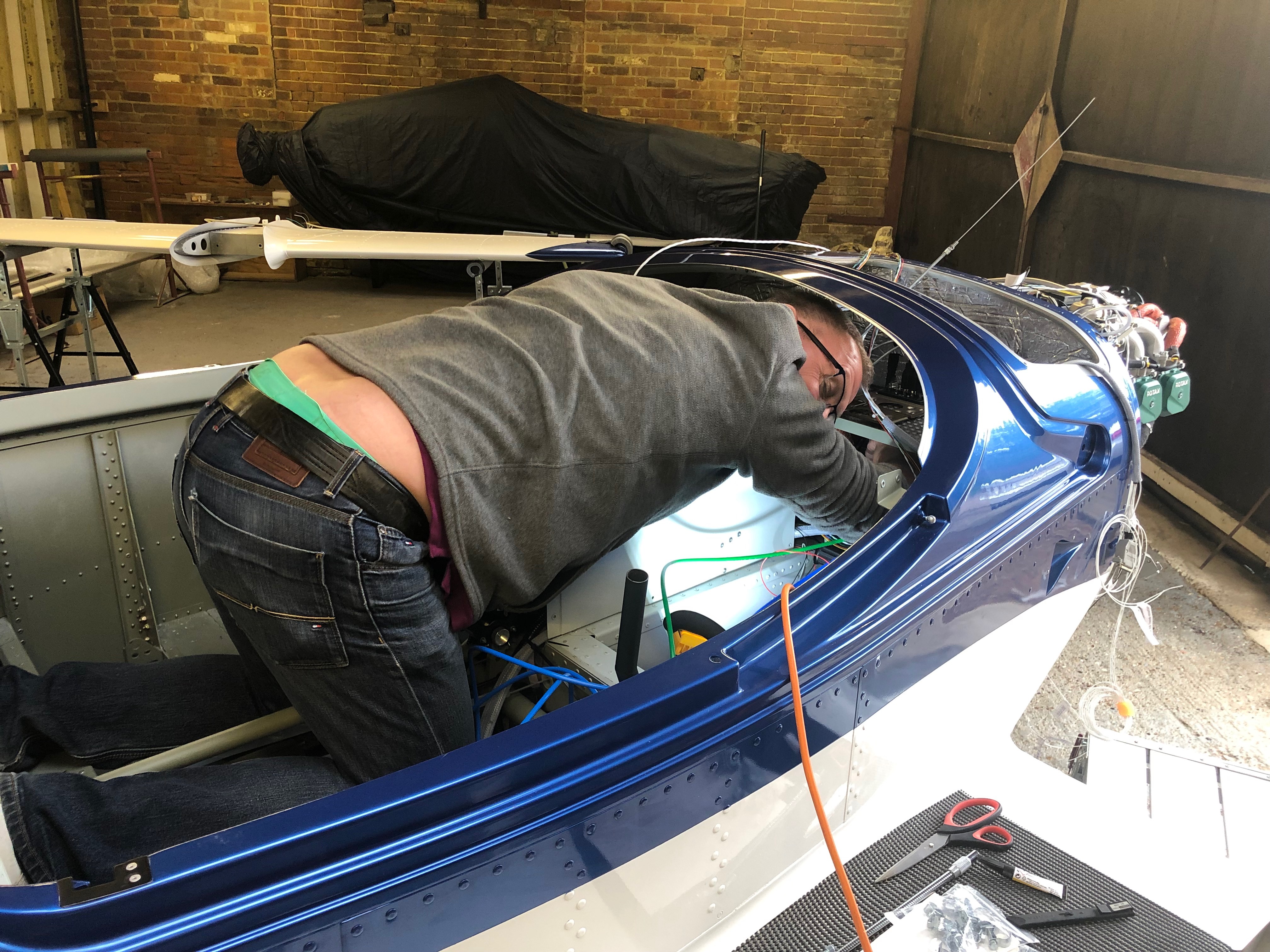
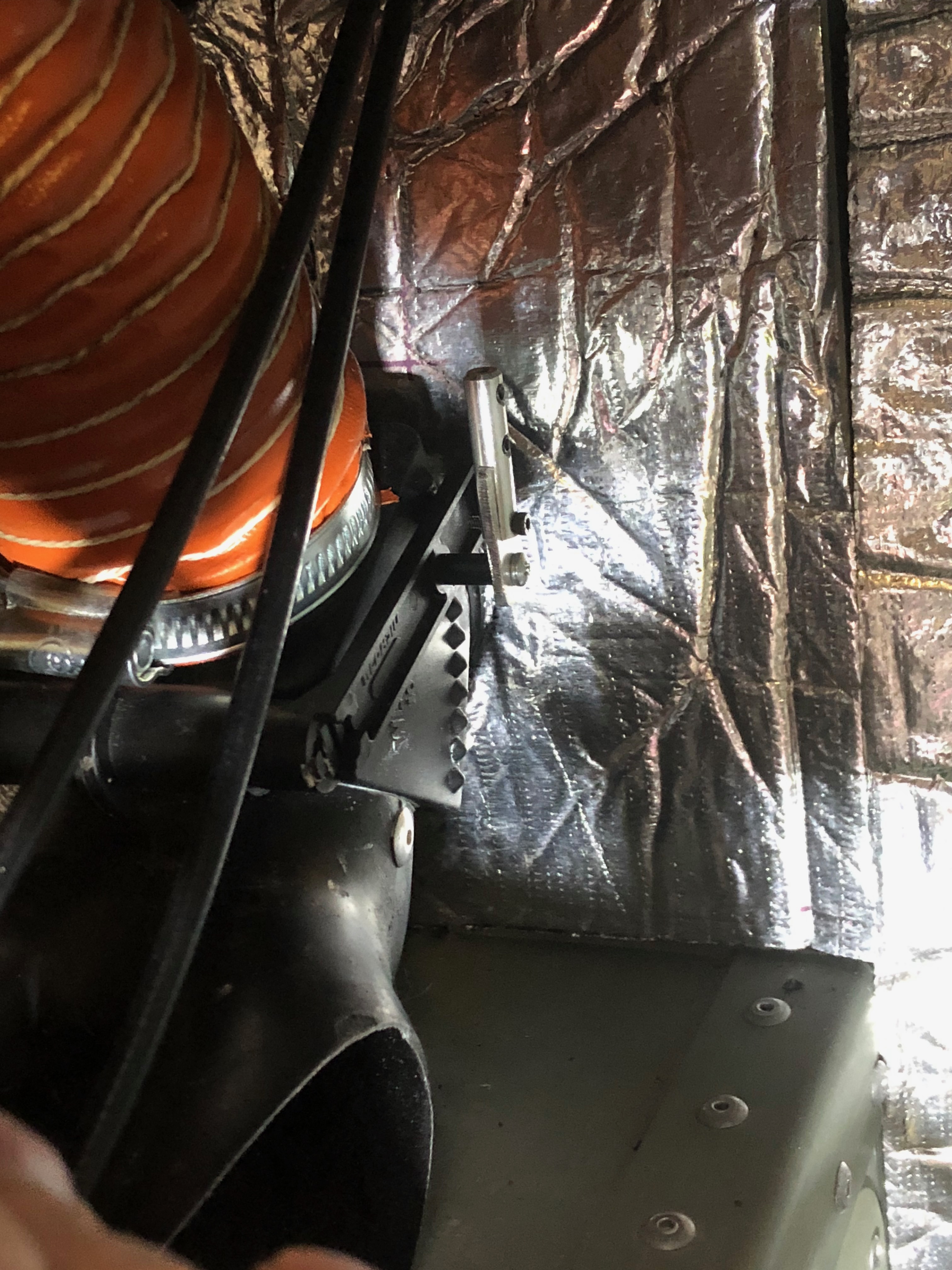
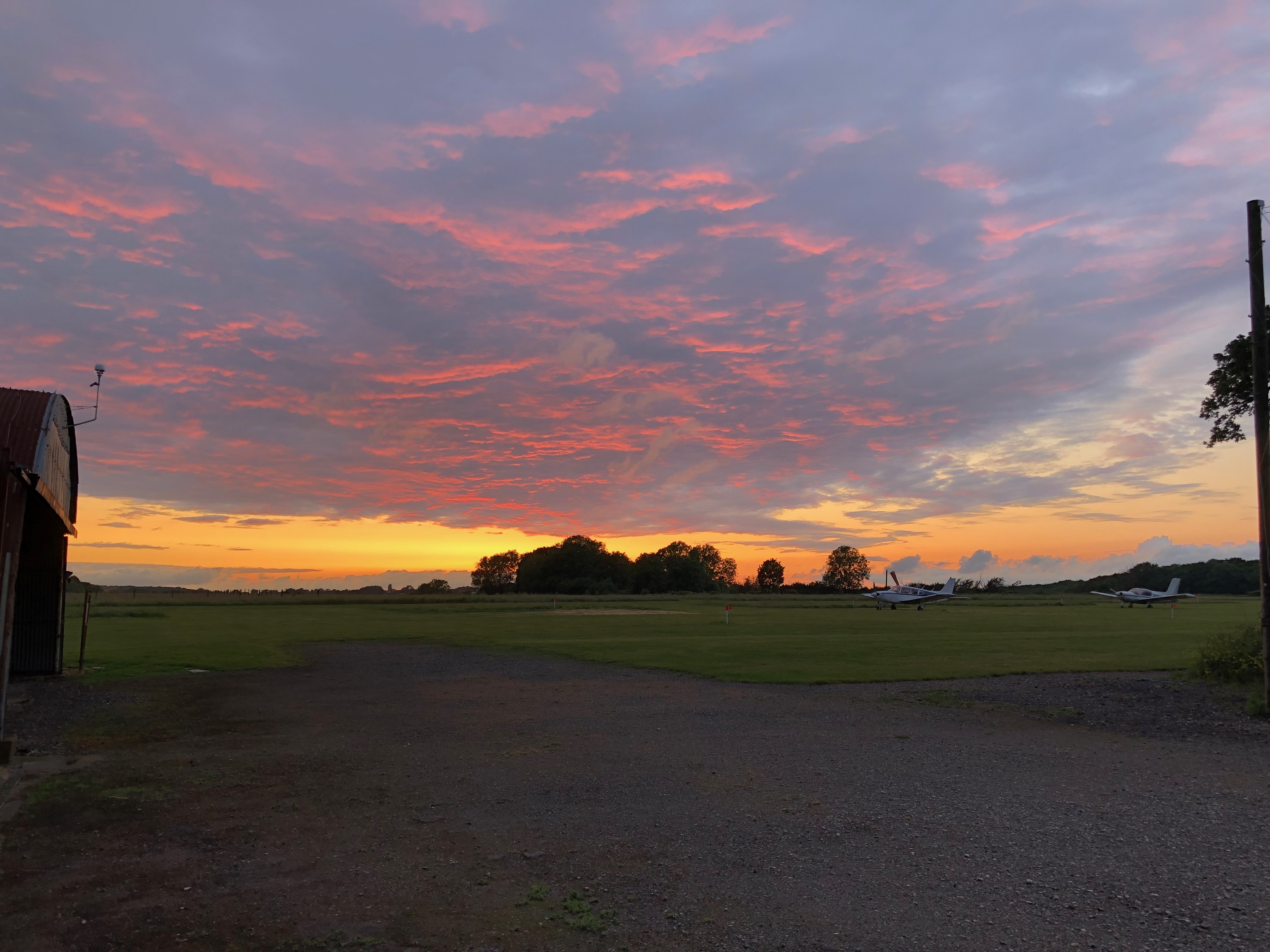
Tom always comes equipped for the job. I think he was was going to work on a JCB not a Bristell!The demist, heater and carb heat control cables routing over the equipment tray.A test of the parking brake proves that the cable will bend and fail to operate without additional support. Inside the centre console there are quite a few other cables and they need to be positioned so they don’t interfere with each other. In addition to this the fuel pipes have to fitted to the fuel selector.Our solution is to prevent the outer cable from bending piece of aluminium tube and then making a bracket to support it in the console.This looks to be a good solution to the problem. A final wire lock ensures that the cable doesn’t move, so full movement is realised.A radio control clevis is used to connect to the cable. Time will tell whether this is a reliable solution.The connector to the heater and……carb heat controls are very straightforward but the outer cables still need to be fully secured otherwise the whole cable will move and fail to operate the attached item.The demist attachment required a different solution and after some thought we came up with the idea of using a piece of 2mm aluminium to extend the RC clevis.The final solution which will do the job. The only thing to do is fit it!So Tom launched into action! It’s all a bit difficult to get to.But the solution worked well.With two out of the three fuel pipes connected and all the wires and cables routed as require we can call it a day. Tomorrow sees the final fit and we can move on to the prep for fitting the panel and prop.Lovely sky as we exited the workshop. Need to get the build finished so we can go fly in skies like these!
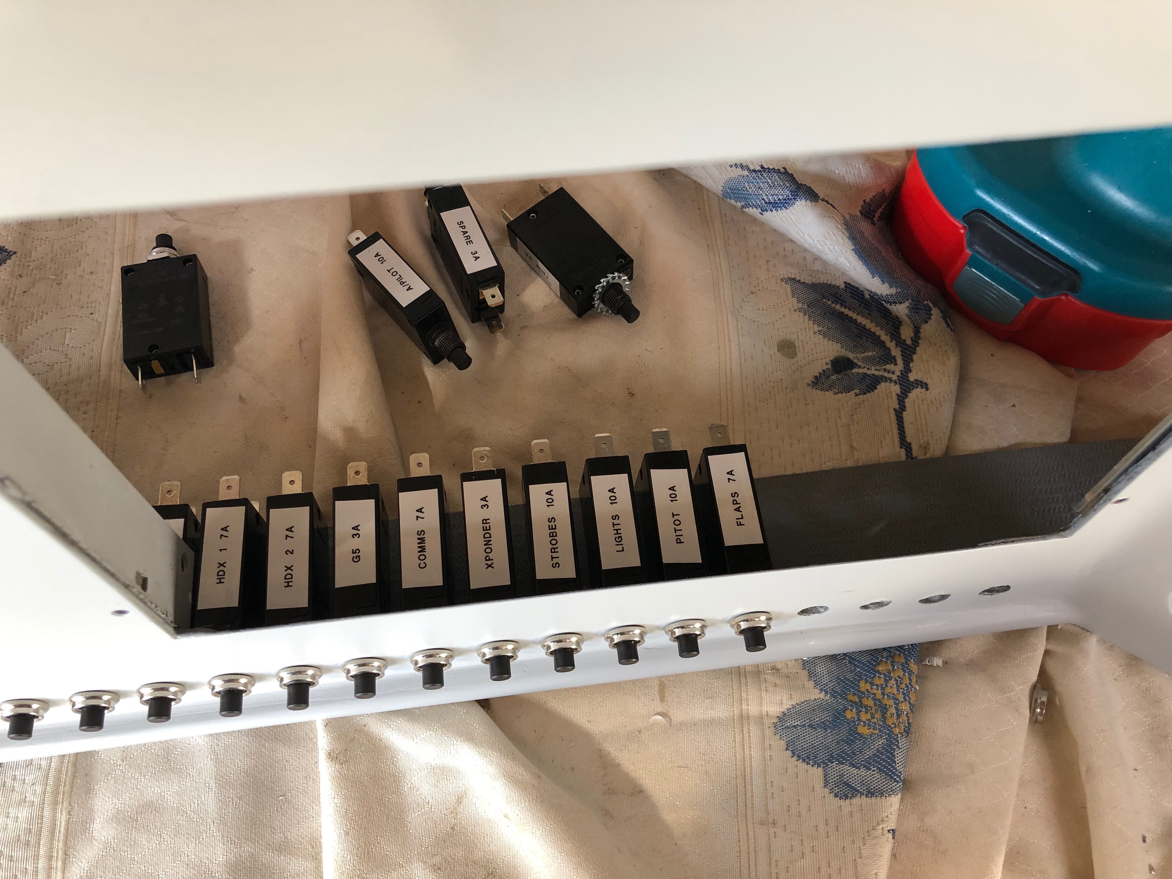
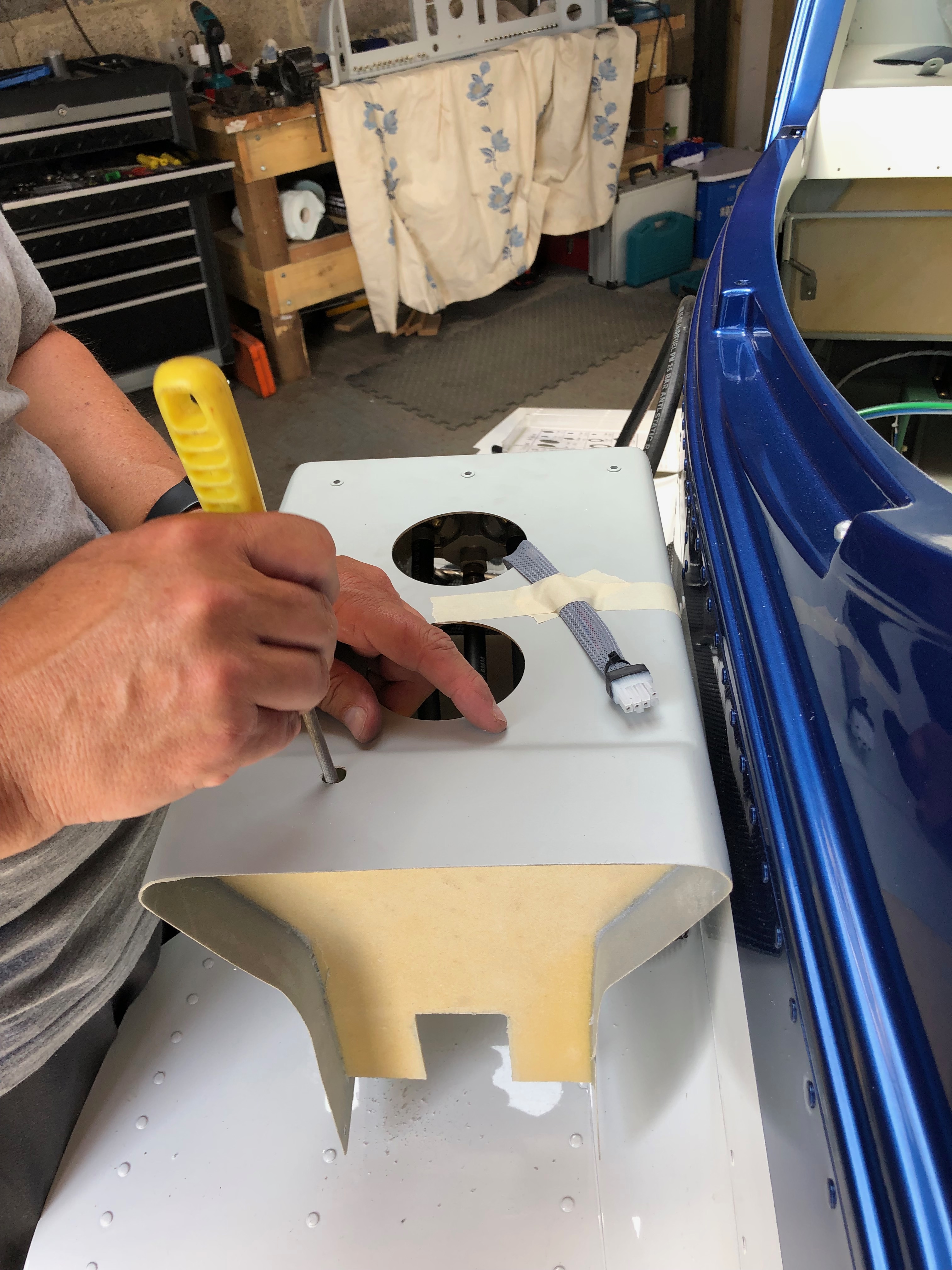
A couple of jobs to focus on today. The first is to fit the circuit breakers and second is to start the fitment of the centre console that includes the control cables for Carb Heat, Park Brake, Cabin Heater, Demist and fuel pipes to the selector and tank lines.
I’ve printed labels using an electronic printer so I can easily identify the circuit breakers and switches once fitted.Unlike the switches that have a hex nut and can be tightened with a spanner the circuit breakers have a knurled ring that is difficult to grip. I found the best way was to adjust some mole grips so they gripped the ring firmly that allowed me to turn the the ring a quarter of a turn at a time. It took some time but got the job done. All the switches and circuit breakers are in now. Very pleased with the result, looks quite tidy!The cables used to control various items have to be routed so they don’t snag. After a couple of trial fits the best route from the front of the panel to the control is to exit the centre console via a hole at the rear. Three cables will exit this way and the fourth which operates the park brake will exit the end of the console and loop back in. This makes sure that the control operates in the correct sense i.e. push is off and pull is on. With the console in place I can test the routing again and once checked I can drill the other holes.The carb heat cable is connected to the carb heat control using a radio control model clevis.The centre console ready to be installed showing the park brake cable that loops round and back in connect to the park brake. Without doing this the park brake would operate incorrectly.Chris has been helping me over the last couple of days but before he left I thought I’d install a screen and power it up. With the ADAHRS unit installed and wired it’s the first time that I’ve seen it myself – looks quite impressive!
I received two pieces of good news today. The first was the dispatch notification of my Airmaster propellor which will be delivered on the 4th June. And the second was that the ignition switch that I ordered 5 days ago was arriving from Germany today! With Chris here for a couple of days he can give me a hand to do some of the jobs that I haven’t got round to like installing the rivnuts for the interior panels and fitting the wing locker seals. I continued preparing the panel for the instrument fit and working out how best to install the centre console.
Chris came down to visit and give me a hand with some outstanding items.As I’ve decided to make the interior panels removable rather than rivet them in Chris’ first job is to install the rivnuts that will take the 3mm button head retaining screws.Who says I’m a slave driver! A happy worker 🙂After the rivnuts the next job for Chris is to fit the wing locker seals to ensure that they are waterproof. As the seals are not included in the kit!?!? I’ve brought some draft excluder that should do the job.Good job done. The seals will ensure that any luggage is kept dryI continued prepping the panel for the instruments. These aluminium ‘washers’ are to spread the load of the nuts when used to secure the instruments.
My bother’s birthday today – Happy Birthday Aitch!
After a lovely Easter in York with friends it was back to action today however I couldn’t quite get ‘into the groove’ for some reason so didn’t do as much as I normally do. So I bled the brake lines to get rid of the air in them, fitted the centre arm rest and started some wiring.
Now I’ve fitted the fuel selector I thought I’d continue to fit the arm rest. The console needs to be cut to accept the throttle quadrant.
It’s important not to cut too much away at any time otherwise you’ll end up with an unsightly gap between the quadrant and the console.
Quite pleased with the result and once secured in place it will look good.
Now for a bit of the electrics. There are several places where a join in the cables need to be made. I’ve decided to use Superseal connectors and they are very neat, easy to disconnect and are waterproof.
Each of the connecting pins need to be crimped onto the wire…
and the then inserted into the connector block. ‘Male’ pins are used for those wires receiving power and female connectors are used for those supplying power. More of the same tomorrow.
Some time ago I had assembled the Andair fuel selector but hadn’t installed it as it wasn’t needed at the time. Today was the day to mount the selector and various controls into the centre console.
On a lot of centre consoles I’ve seen, the fuel selector and the flap control are positioned side by side in this recess. Personally I thought it would be better to keep the fuel away from any electrics, so have decided to mount the flap selector on the instrument panel.
The centre console which is made from glass fibre and re-enforced with carbon fibre panels. I marked the centres and positioned the selector where I thought it would look good.
After measuring and remeasuring the position to drill the mounting hole I used a step drill to cut a 26mm hole. It was only after doing this I found that Andair actually provide a template to help do this. Note to self: RTFM!
No problem with my measurements though and the selector cover goes on ok. I can now mark up where the Carb heat, Park Brake, Heater, and Screen De-mist controls go.
Although there are strengthening panels build in to the console I thought it would be good to further strengthen where the push/pull controls are mounted so made a couple of brackets…
and use a piece of glass fibre to secure them in place. This further supports fuel selector and controls.
This is what it looks like after the glass fibre has set.
Re-drill the holes
and the finished console ready for the the selector and controls to be mounted.
The cables are secured in place with nuts and I’ve put another washer on the back to spread the load even more. Taking no chances!
The inners are inserted to finish off. I will be able to mount the console and work out the runs for all the cables and make sure they work in the correct sense i.e. Pull for on, push for off.
There are 2 brackets that secure the instrument panel and the centre of the panel is supported by the console.
The console and instrument panel temporarily installed to see how it looks/works. I can now prep for the install of the screens and various switches, circuit breakers and warning lights once I’ve completed my electrical design.
Following the build of my Bristell NG5 Kit No. 382 Registration G-MLSY