A few jobs whilst Andy is still here to help including the internal trim panels, OAT sensor, bleeding the brakes and pitot system installations.
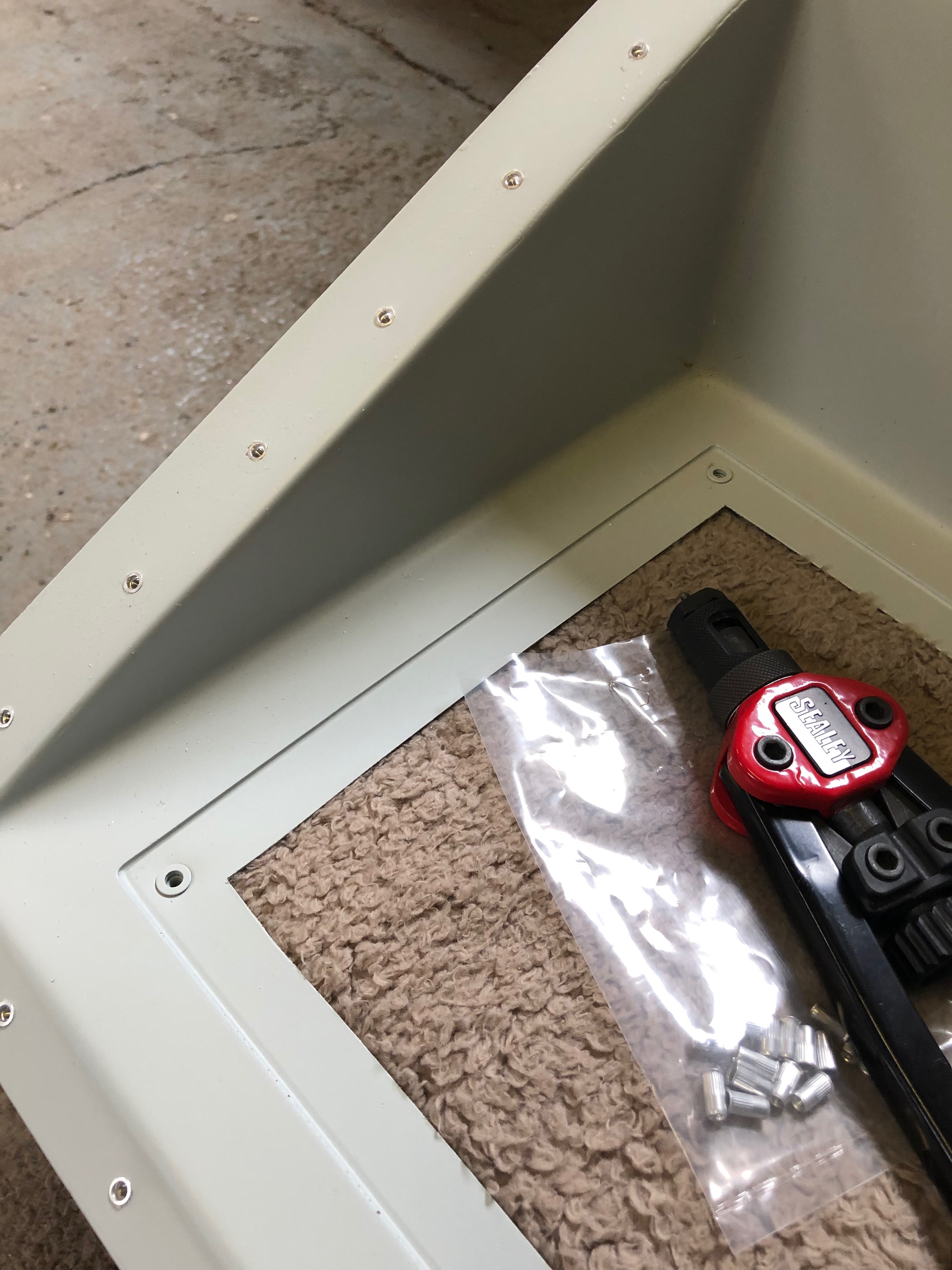
The rear panel in normally riveted into the aircraft and has two access panels cut in with covers. I thought it would be a better idea if it was removable so decided to use 3mm screws and rivnuts to secure it instead. First job drill the 5mm hole for rivnuts.
The install the 37 rivnuts in the rear panel…
and 8 along this panel.
The finished job which looks quite good.
The supplied OAT cable is several metres long but I’ve decided to mount it close to the ADAHRS unit so I shortened it out by cutting some wire out of the the middle of the cable and soldered together which removes the need to crimp new ends on.
The OAT sensor is fitted from below and secured with a nylon nut and washer. I’ve used a bit of silicon to make it even more water tight from below before fitting.
The finished installation needs to be within 2 degrees of level in all planes so once the aircraft is finished I may have to shim the unit.
After bleeding the brakes I have two very small air bubbles left in the brake lines that need to be purged. The normal method didn’t work so thought using an electric pump might work. The whole thing turned into a disaster. The first attempt resulted in the electric pump sucking in air. The second attempt resulted in the pump forcing off the pipe. Then on the third attempt the pump failed after 5 seconds of continuous use. I gave up! will try again another time…
Moving onto the pitot installation. I’ve purchased an electrically headed pitot that needs power to it so I need to run power to the unit. There is conduit in the wing so will use this but it’s difficult to get to.
The only place I can easily mount the heater power unit is on access cover but the unit is just little bit big for the access hole so I had to cut the corners of the mounting bracket.
It’s secured onto the of the access panel with M4 screws, washers and nylocs.
It’s a perfect fit..
The view from the underside.
just needs to be connected and wires run up the conduit.
It’s a very tight fit but need to get my arm into the access panel to get to the conduit.
Andy came down to visit again so got him to work straight away! Now the ADAHRS and GMU mounts are in the units can be installed and the Pitot system can start to be installed. The aircraft was also rigged to to check for fitting and alignment which will allow Ian Daniels to sign off that stage.
I ordered some brass screws to secure the ADAHRS unit in place but they were too long so Andy’s first job, correct my mistake and cut 10mm off!
Getting Andy straight down to business.
A pilot hole (drilled by a Pilot!) for the OAT was opened up from below – I’m sure it could have been done from above but it got Andy on the crawler board 🙂
I sat the mounts quite a way back in the fuselage to keep them away from any EMI but it made securing quite tricky. A job for Andy!
The ADAHRS…
and GMU units installed.
The Pitot system pipes need to be installed so holes are drilled and grommets will be fitted to support the pipes and prevent chaffing.
One of the sign off stages is to check that the wings fit! Ian Daniels guiding the process of attaching the wings for checking.
Wings on and she starts to look more like an aeroplane!
My bother’s birthday today – Happy Birthday Aitch!
After a lovely Easter in York with friends it was back to action today however I couldn’t quite get ‘into the groove’ for some reason so didn’t do as much as I normally do. So I bled the brake lines to get rid of the air in them, fitted the centre arm rest and started some wiring.
Now I’ve fitted the fuel selector I thought I’d continue to fit the arm rest. The console needs to be cut to accept the throttle quadrant.
It’s important not to cut too much away at any time otherwise you’ll end up with an unsightly gap between the quadrant and the console.
Quite pleased with the result and once secured in place it will look good.
Now for a bit of the electrics. There are several places where a join in the cables need to be made. I’ve decided to use Superseal connectors and they are very neat, easy to disconnect and are waterproof.
Each of the connecting pins need to be crimped onto the wire…
and the then inserted into the connector block. ‘Male’ pins are used for those wires receiving power and female connectors are used for those supplying power. More of the same tomorrow.
Some time ago I had assembled the Andair fuel selector but hadn’t installed it as it wasn’t needed at the time. Today was the day to mount the selector and various controls into the centre console.
On a lot of centre consoles I’ve seen, the fuel selector and the flap control are positioned side by side in this recess. Personally I thought it would be better to keep the fuel away from any electrics, so have decided to mount the flap selector on the instrument panel.
The centre console which is made from glass fibre and re-enforced with carbon fibre panels. I marked the centres and positioned the selector where I thought it would look good.
After measuring and remeasuring the position to drill the mounting hole I used a step drill to cut a 26mm hole. It was only after doing this I found that Andair actually provide a template to help do this. Note to self: RTFM!
No problem with my measurements though and the selector cover goes on ok. I can now mark up where the Carb heat, Park Brake, Heater, and Screen De-mist controls go.
Although there are strengthening panels build in to the console I thought it would be good to further strengthen where the push/pull controls are mounted so made a couple of brackets…
and use a piece of glass fibre to secure them in place. This further supports fuel selector and controls.
This is what it looks like after the glass fibre has set.
Re-drill the holes
and the finished console ready for the the selector and controls to be mounted.
The cables are secured in place with nuts and I’ve put another washer on the back to spread the load even more. Taking no chances!
The inners are inserted to finish off. I will be able to mount the console and work out the runs for all the cables and make sure they work in the correct sense i.e. Pull for on, push for off.
There are 2 brackets that secure the instrument panel and the centre of the panel is supported by the console.
The console and instrument panel temporarily installed to see how it looks/works. I can now prep for the install of the screens and various switches, circuit breakers and warning lights once I’ve completed my electrical design.
Music: The Greatest Showman reimagined and Snow Patrol.
Finishing off the insulation installation, first fit of centre console, autopilot servo install and filling brake system with Aero Shell 41.
One quick job this morning now all the other pipes have been fitted is to run a piece of piping from the water expansion chamber to the water bottle.
I have been given templates for the insulation so I can cut them to size without too much effort.
Some notches, cuts and holes need to be made to make sure it sits properly on the firewall.
It’s a tight fit behind the rudder pedals which makes it difficult to handle once the backing paper has been removed.
The final pieces are fitted around the heated inlet.
The finished insulation, hopefully this should reduce noise from vibration of the firewall and the engine.
Now the servos brackets are in position the servos can be fitted. First the roll servo.
It’s very fiddly and would have been much easier to fit the servo to the bracket whilst it was out of the aircraft.
The pitch servo with the movement limiting bracket fitted which stops the motor running over centre. I still can’t finish the installation as there were items missing from the kit supplied to me – very frustrating as I can’t refit the controls until I fit the roll servo arm.
A first fit of the centre console in readiness for the fuel selector. Need to check with the instrument panel in place to check that the flap control cable is long enough to fit on the panel otherwise is will need to be mounted here instead which I would like to avoid.
After fitting the insulation need to reconnect and tighten the brake hoses before filling.
The brake fluid is filled from the bottom so some plastic pipe is wire locked onto the brake calliper nipple so stop it slipping off. The nipple is unscrewed to allow the fluid to flow into the calliper.
An oil can that has been thoroughly cleaned is filled with Aero Shell 41 and the plastic pipe is fitted to the nozzle.
The filling commences after releasing the park brake valve.
When the fluid reaches the brake oil bottle the brake calliper nipple is tightened and the process is repeated for the lefthand side brakes.
Filling complete but some air bubbles are present. They will need to be purged before use otherwise the brakes may not operate properly.
I took delivery of the servo brackets and wing locker fittings after a lengthy wait. Unfortunately bit were missing, again. The servo arm, bolts, washers and some rivets were missing from the servos mounts and the nuts, washers and large screws for the locks were missing from the wing locker kit. It can be very frustrating and delays the build.
Despite this at least I was still able to mount the servo brackets. During the install I found myself like a contortionist whilst I installed the brackets and front trim panels with an air rivet gun.
I spent some time this morning making sure that I can get to all the screws once installed. The cut outs are for the EFIS backup batteries. The insulation is fire resistant and will provide sound proofing too. It is secured into position by a self adhesive backing.
The install consists of 2 brackets one for roll and one for pitch. To install them I will need to remove the controls.
There’s quite a few nuts and bolts to remove including those holding bearings.
The control assembly, sometimes it feels like you’re dismantling the aircraft instead of building it when you have undo some of the work you’ve already done.
Now the area is clear I can start to install the brackets.
The bracket is positioned and 4mm holes drilled through the floor of the aircraft.
From underneath 3 holes are drilled which will further secure the bracket.
Ian Daniels has kindly lent me his air rivet gun and compressor which should make installation a little easier.
Once the holes are de-burred, and anti corrosion jointing compound is applied the bracket is cleco’d in place and riveted from below.
The final bracket installation. Once I have the rest of the missing bits I’ll be able to complete the roll installation.
To enable the installation of the pitch servo bracket 3 rivets need to be removed. The first thing to do is knock the centre hardened pin out…
and then drill the head of the rivet off and then know the rivet out.
The bracket is placed and checked that it’s positioned correctly.
One of the rivet holes don’t quite line up which is surprising but will need to be drilled out to enable it to be riveted.
Ian Daniels come to the rescue again as he lent me this 90 degree drill attachment that allows me to drill the hols for the rivets. There isn’t enough space to drill the holes without this.
The pitch servo riveted in place. Quite please with the bracket installations but they take a lot of time and I’ve still got to re-install the controls!
So I can install the insulation in the door wells I need to install the forward trim as they are riveted in place. It’s a tight fit behind the rudder pedals but they can’t be fitted until after the rudder pedals are fitted as there is insufficient room.
The air rivet gun makes it easier to get to the rivets but because it’s size I won’t be able to use it for all the rivets…
So for some I need to use the hand rivet gun but it’s very awkward to use in such a tight space.
It took some time, longer than expected however the left panel is in…
and so is the right. Tomorrow I will refit the controls.
Due to limited space I couldn’t drill the second set of holes for the retention system. Luckily Ian had a 90 degree attachment the allowed me to drill the holes.
The holes for the rivets that will secure the bracket.
Sometimes you have to leave certain jobs because an immediate opportunity comes up for someone to help you swap wings. This is what happened when I had starboard wing up on the stand so I didn’t get chance to fit the strobe light. So today’s the day to do it.
Once the holes are drilled they need to be countersunk otherwise the strobes won’t fit flush.
Some Loctite 243 on the screws and then they are pinched up, not too tightly, otherwise they will disfigure the rubber mount.
The finished job, let’s hope it matches the other wing!
A job I kept forgetting to do is to add a breather pipe to the oil tank.
Now they can be secured with the drip tray and air intake breather tubes that Andy fitted yesterday.
I wanted to try to reduce the amount of vibration and droning from the firewall and noise from the engine. I purchased some sound & vibration deadening heat resistant foil back foam that will do the job.
After cutting to size, I’ve made the service holes to match the firewall and added grommets to make it a neater job.
I used some thinners to remove the printing on the foil before fitting. Looks a good fit.
I now need to undo some of the work I’ve done on the brakes and fit the front lower panels so I can fit sound deadening on the firewall behind the rudder pedals but run out of time today so will finish this job Monday.
Andy is here for another day so I can work on some outstanding things that need doing on the the wings.
With Andy here he can help me move the wings so I can get some of the outstanding work on them done.
The aileron hinges are of the piano top and need to be fitted, lubricated and locked in position with split pins.
The split pins I need are 1/16″ x 3/8″ but I only have a longer version so they are cut down in size with side cutters.
They are fitted from the top of the wing so they can’t fall out in service if the locking fails.
The ends are bent over to lock the pins in place.
The Aileron actuator and flap hinge bolts are fitted and tightened against the bearing. They have Nyloc nuts to prevent them becoming loose.
A check for free movement after tightening is made.
To check any movement I’ve run some torque seal over the nut and threads. If the torque seal cracks it indicates movement and will need to be checked.
The hinge is lubricated with white lithium grease.
Once completed, the exact same work is carried out on other wing.
The elevator hinge is also a piano hinge so will need to have the same work carried out as the ailerons. The trim tab is already fitted and the hinge is secure when manufactured.
There’s two pieces of wire in the elevator which needs to be adjusted and secured at both ends and lubricated with white lithium grease.
I decided to change the landing light retaining screws to black cap head screws which I think look better.
Andy has come to visit for a couple of days and give me a hand on some of the items that need 2 people, like lifting and turning the wings. One of the jobs that would be good for us to start on was carrying out the final fit of the lower cowl that needs modification to gain access to the fuel check valve and ensure that there is sufficient clearance around the radiators and exhaust is service.
Once the cowl is fitted the ‘tight’ spots need to be marked.
Also the position of the hole for the gasocolator fuel check valve is marked.
The cowl is made from carbon fibre so the tight spots are filed with a course file to start and finished off with wet and dry.
The cowl is also adjusted for the exhaust downpipe.
Next a hole needs to be drilled in the cowl for the drain valve.
and opened out with a step drill.
Plenty of room now so no chance of rubbing against the exhaust…
… or the water radiator.
The hole is in a perfect position but will need to be opened up further.
The Rotax installation involves running hoses and tubes from everywhere, to everywhere. One of the last tube runs are the drains from the carb drip trays and the air box plenum.
They need to be run to exit underneath the fuselage but miss all the hot spots like the oil, water and exhaust pipes. it’s not straightforward.
But Andy has done a good job.
Meanwhile, I finish off designing and installing the equipment tray retention system which will be rubber mounted to dampen vibration and protect the avionics units mounted on it.
One down and one to go tomorrow…
Andy taking the captains seat as usual after a very productive day.
A number of jobs planned for today. Complete the engine NACA ducting, install the clevis pins to the carb heat control and cabin heater, install the fuel pressure sensor, install the engine intake air box, install the MAP sensor pipe, adjust and set the cowl quick release fasteners and install the control stick torque supports.
The fuel sensor and adapter were left to set with Loctite 577 overnight so can now be fitted to the fuel hose that I had added for it.
The hose is secured with a hose clamp and fire sleeve is added which is secured in place with locking wire.
The sensor is secured against movement and vibration with a stand-off.
These are the clevis fittings that are used on the carb heat, cabin heater, screen de-mist and park brake.
Now the sealant is set, the air box is mounted on a couple of brackets off the engine mount. It’s secured with a couple of Nyloc nuts underneath. Two short pieces of sturdy rubber hose are fitted over the carburettor inlets and the air box and provide a flexible joint between them.
They are secured in place with jubilee clips.
The SCAT ducting is secured in place with jubilee clips to the air box intake and the starboard lower cowl side NACA duct.
The ducting to the port NACA duct is run to the rear of the exhaust and then into the centre inlet on the heat exchanger, secured with jubilee clips and held in position with a couple of tie wraps.
Port NACA duct.
Even with all the space that the Bristell has It can get a bit tight with all the hoses that are required.
The MAP sensor has already been mounted so just needs a pipe to be run and of course some wiring at a later stage…
I’ve used 5.6mm ID R9 fuel hose between the carburettor balance pipe and the MAP sensor.
The quick release fittings on the fuselage have been riveted in place and now require them to be adjusted and set. First thing is to screw them in…
until they are flush with the cowl.
Once adjusted the pin can be pulled that sets them into position.
They are released by a quarter turn of the Philips screw and the fitting stays set in place.
I still need to repeat the process for the top cowl and the oil inspection cover. Ian will be installing the fittings during next week. Unfortunately the rivets need to be ‘squeezed’ and I don’t have the tool to do it.
Now I’ve picked up the control stick torque arms I can start work on the control sticks.
The fittings need to be checked and secured although they will need to be adjusted when the wings are fitted to centralise them, set the limit screws and check aileron deflection are correct.
The torque arm is attached at one end using the bolt from the control stick bearing.
The other end is secured with a 4 x 15mm rivet.
Both torque support arms fitted, completing a fairly productive day.
I’m still not 100% sure on the layout of the screens and associated control panels so I thought it would be good to add the pilot seat so I could check different layouts.
Once the seats were installed I could sit in the aircraft as I would normally fly it. The panel here has most of the bits I need but is missing the flap switch, some warning lights and the air vents.
I’ve stuck the pictures on using glue dots that allow me to move the pictures about. I can then do a ‘touch’ test on the layout to see what works best.
Following the build of my Bristell NG5 Kit No. 382 Registration G-MLSY