Today plan is to finish off some tasks that will see the completion of the oil system, exhaust system, NACA duct, and installing the rest of throttle cables ready for the throttle quadrant install.
The hose clamp are added to the oil return line…
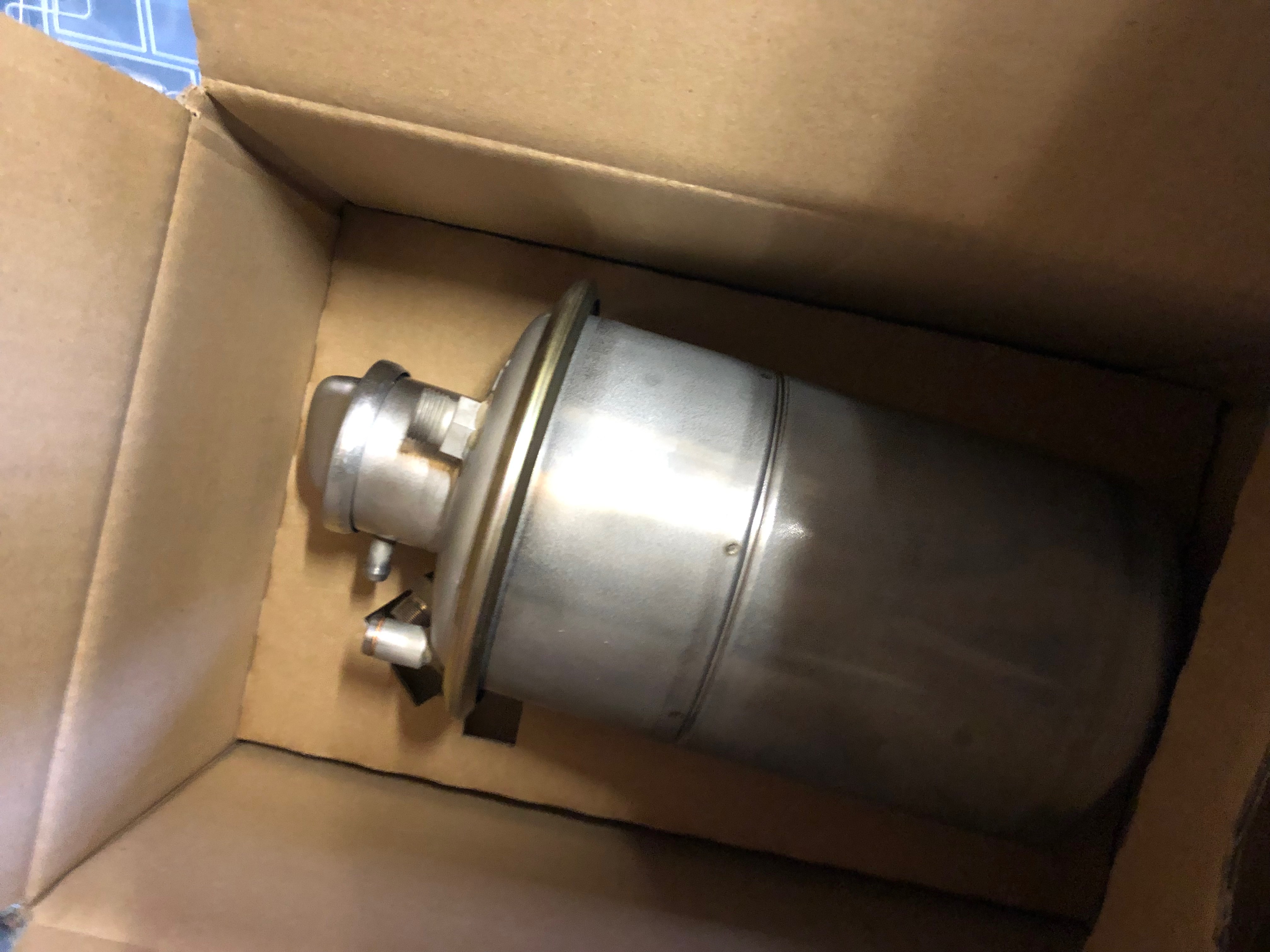
and the oil bottle. I’ve tried to position the clamps to make sure they are easier to get to for maintenance but out the way so someone working on in the engine bay won’t snag their hands or clothing on them.
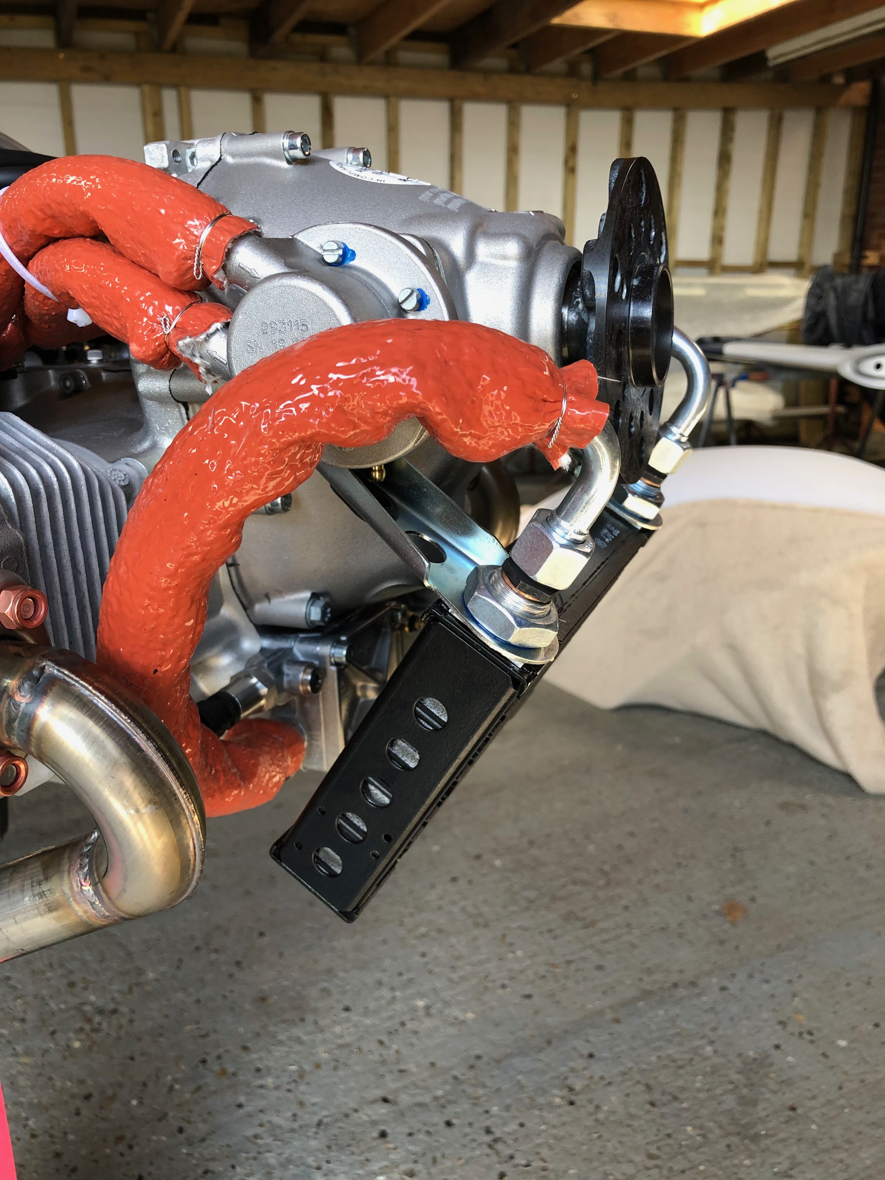
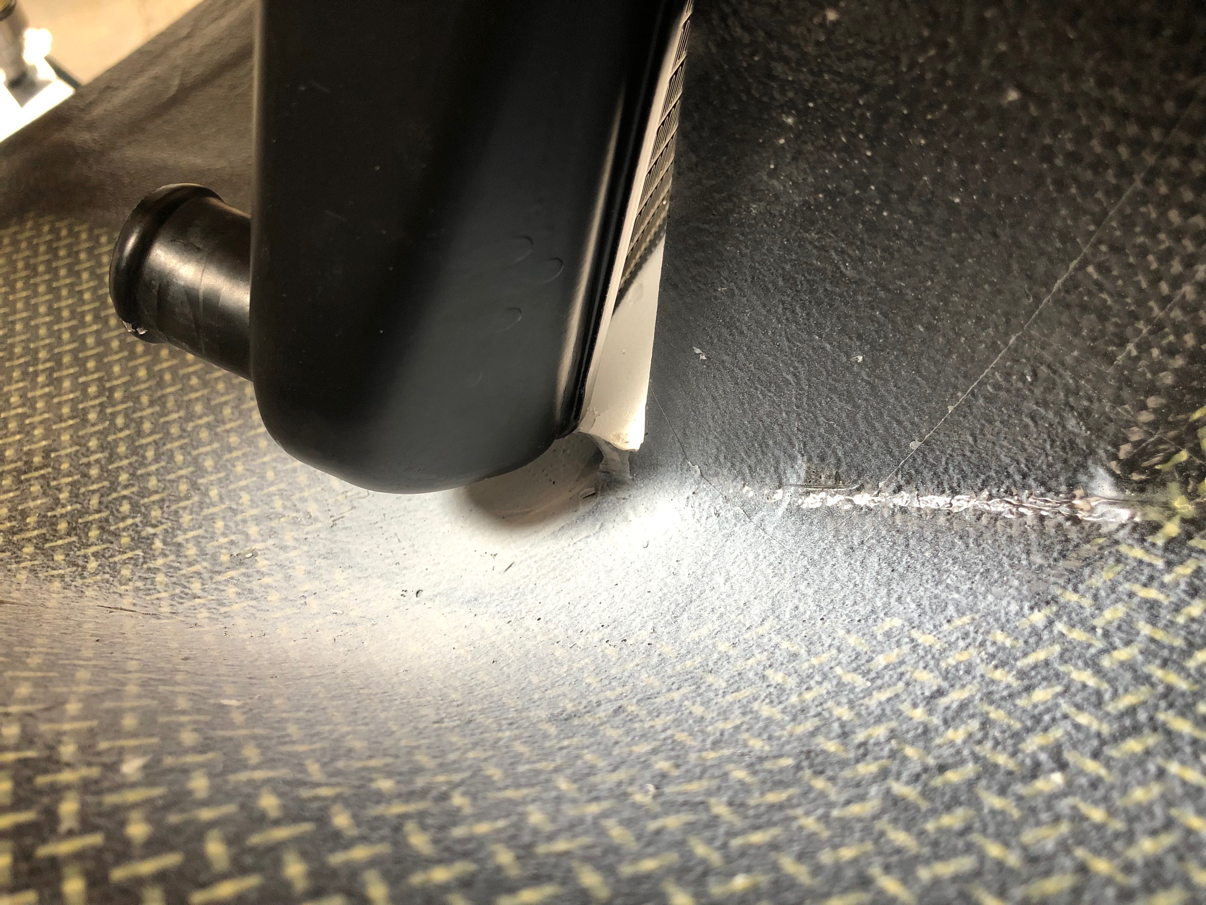
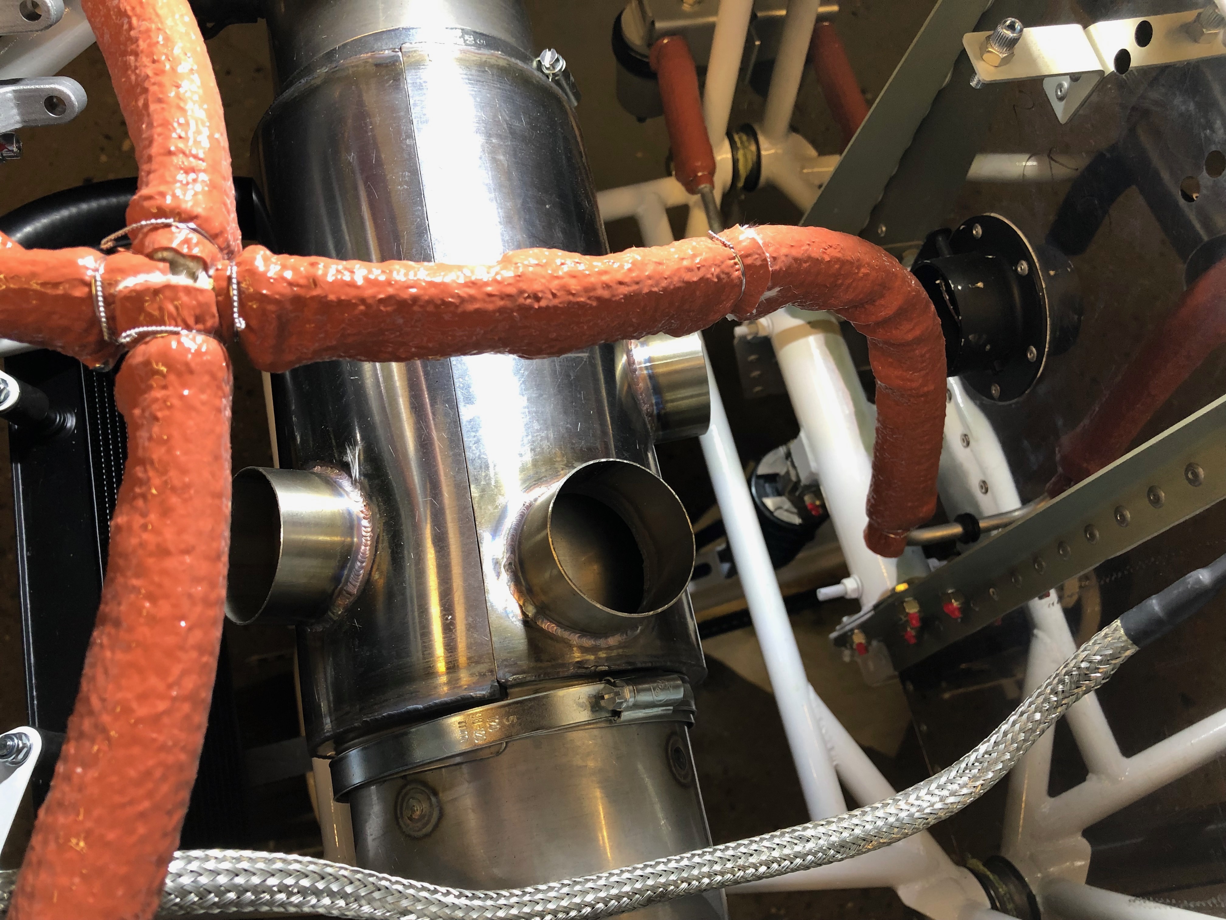
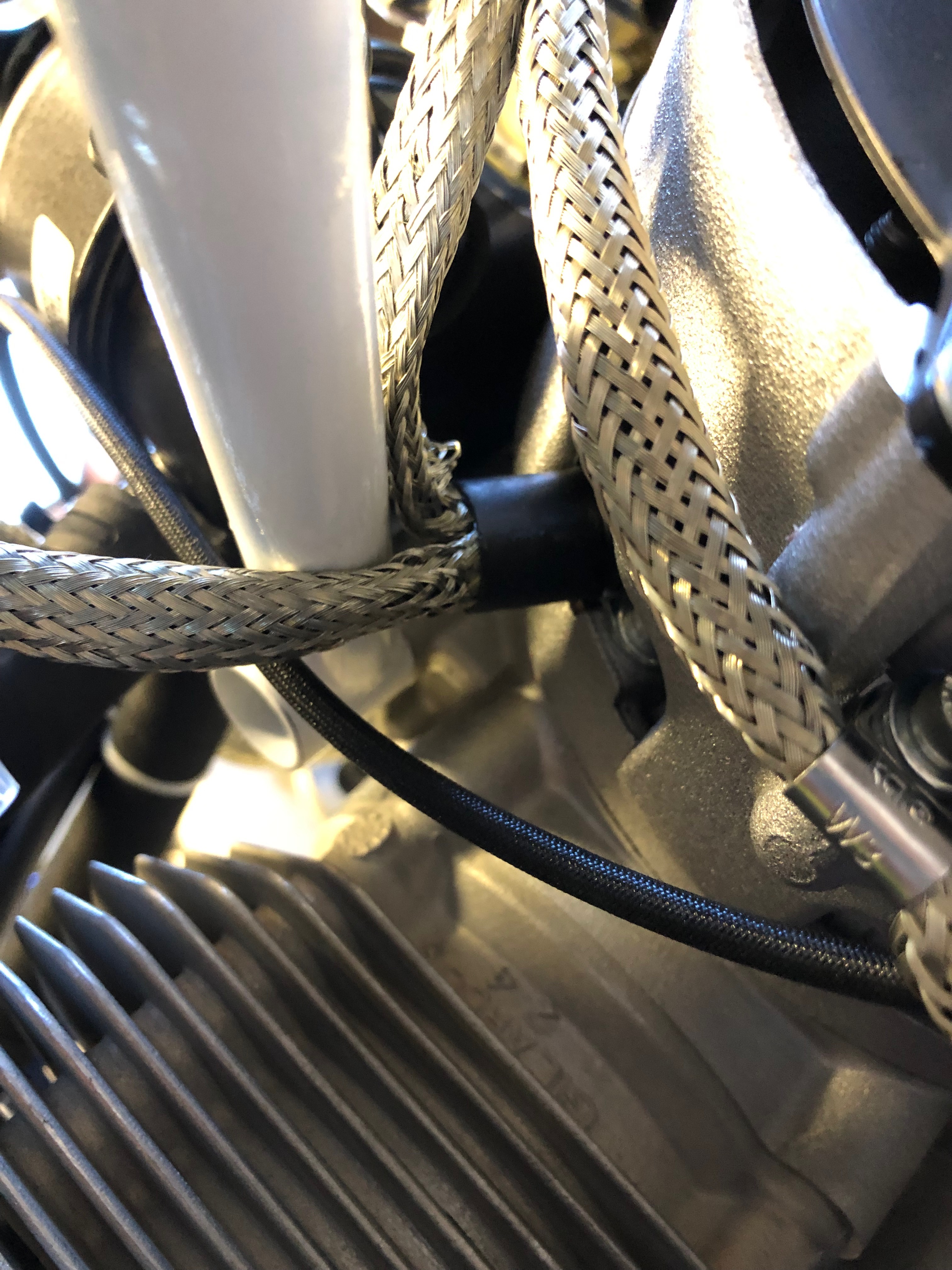
The oil pump to oil radiator pipe is clamped and fire sleeving is added as the pipe runs very close to the exhaust down pipe.
Fire sleeving should protect the oil hose but I will be adding some exhaust wrap to further protect the pipe. The oil system is now complete.
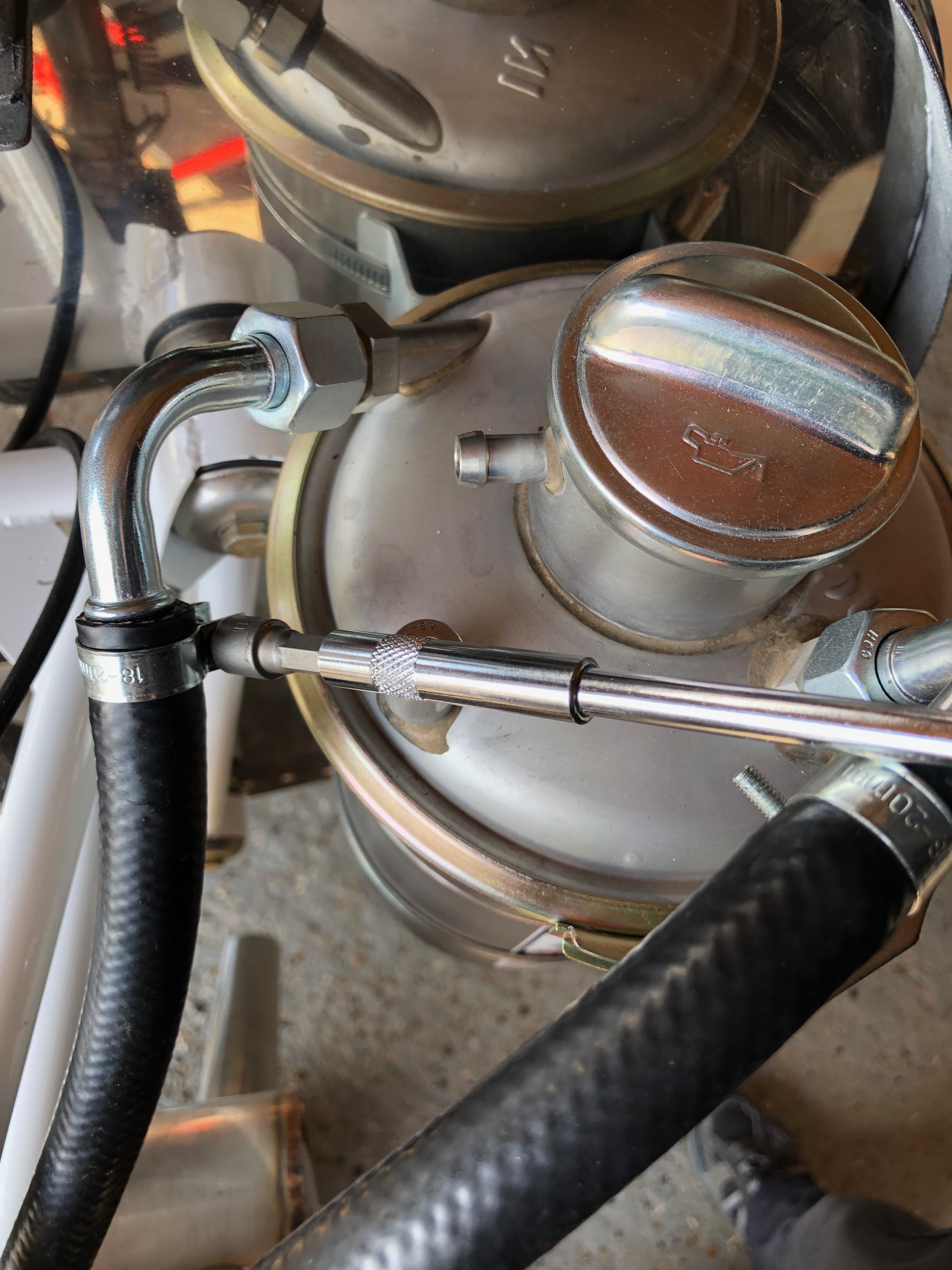
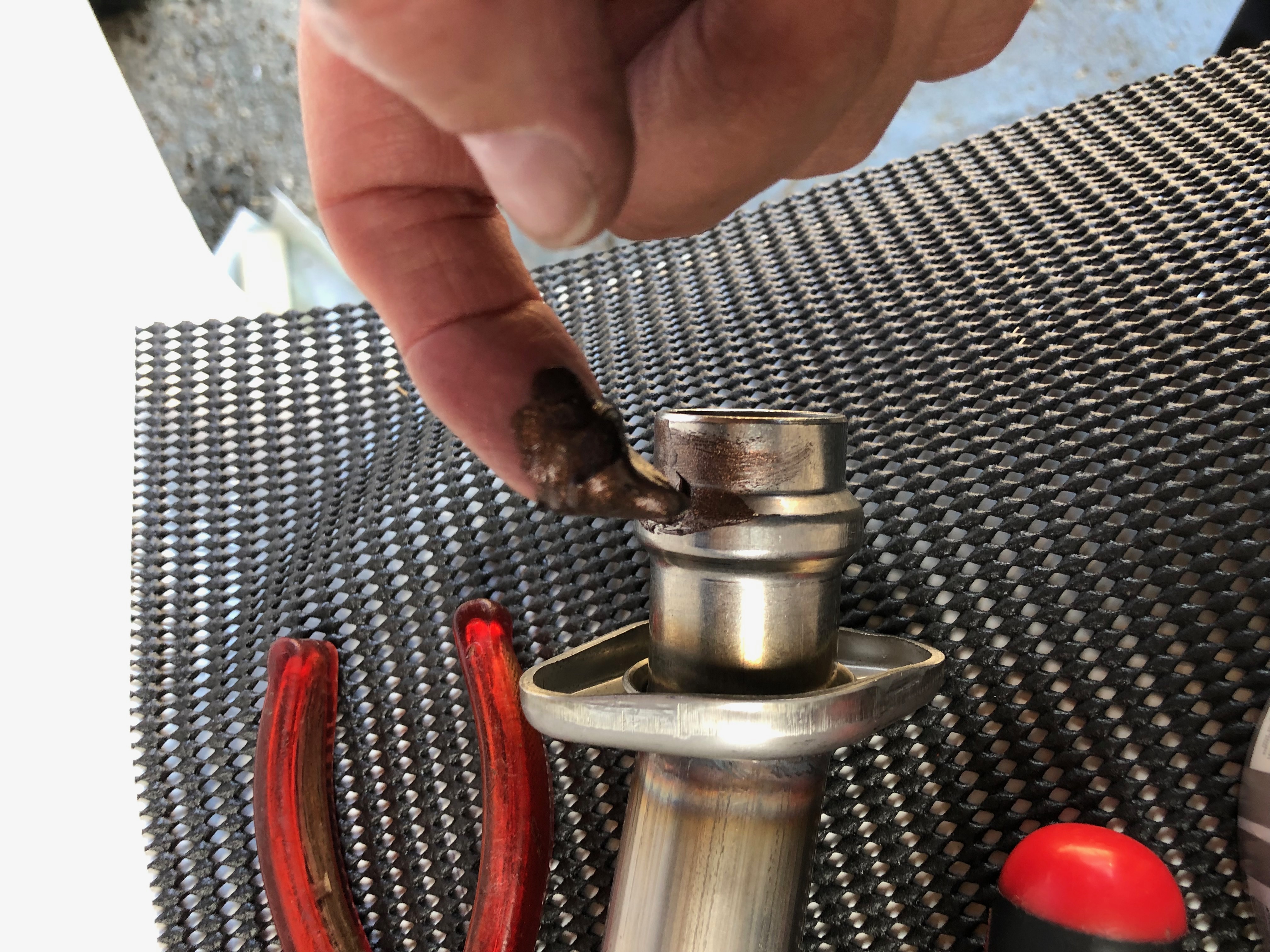
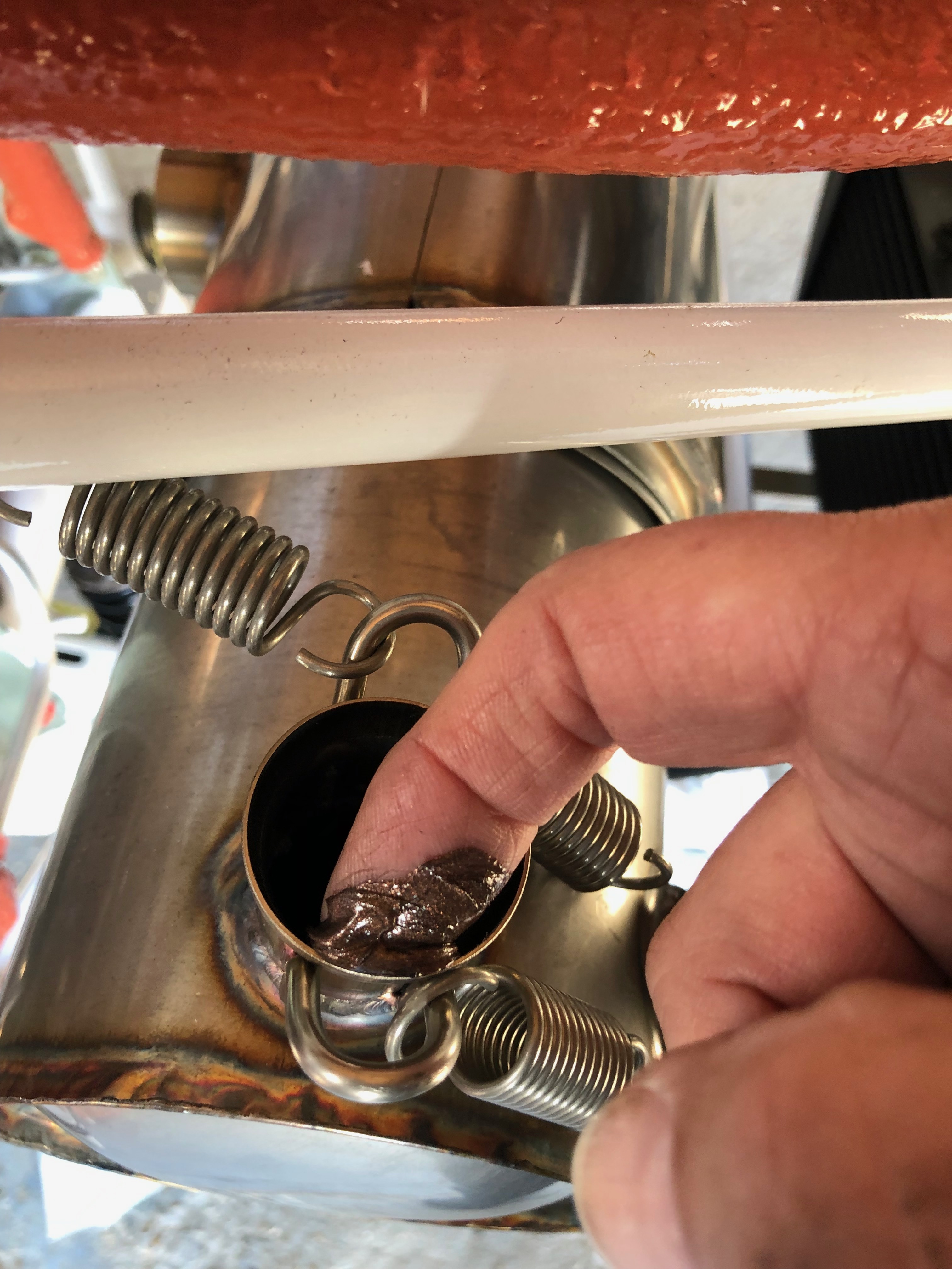
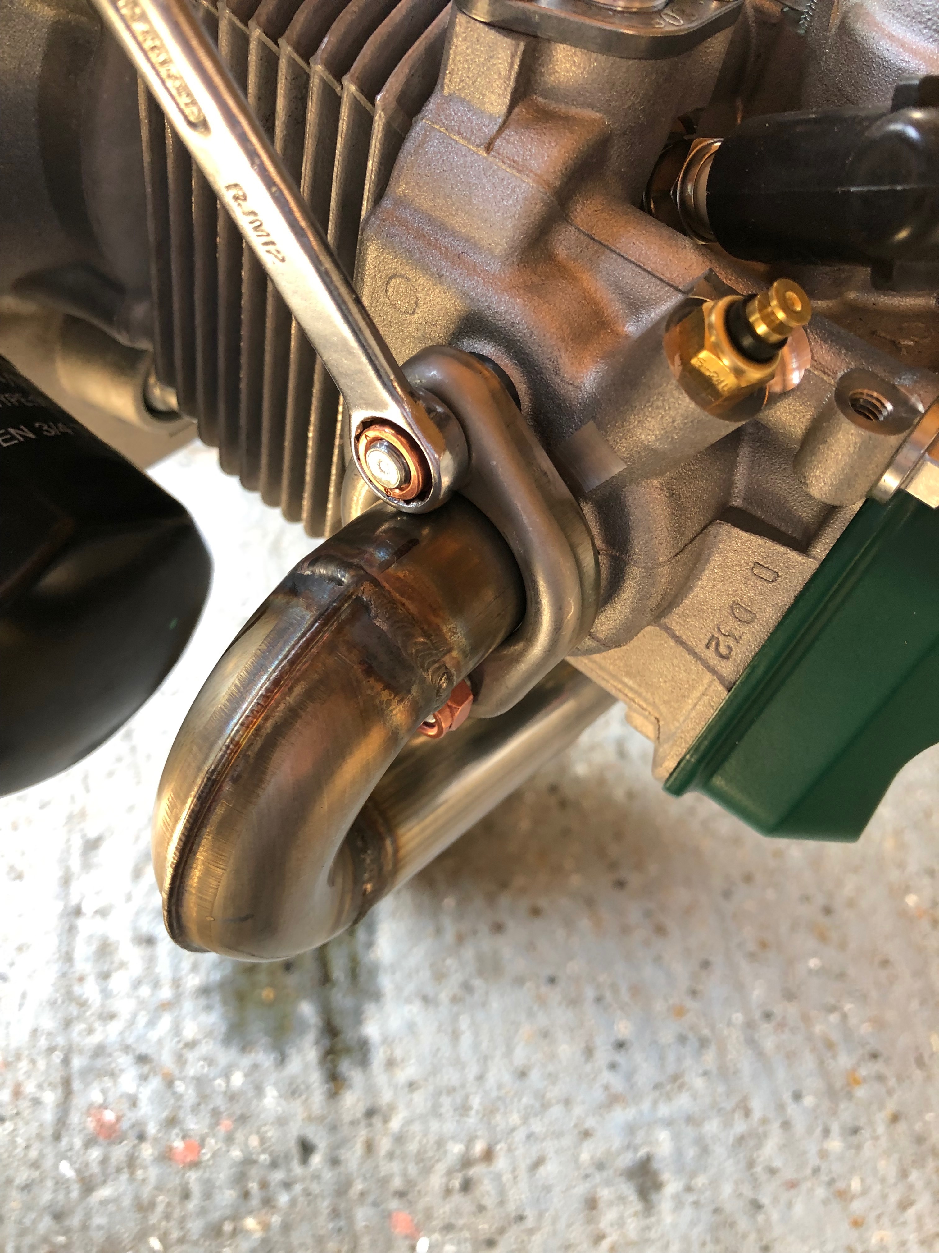
To finish the exhaust system install I need to apply some copper ease to the pipes to enable them to move slightly in service.
and also on the exhaust connection pipe.
After checking the run of the pipes the nuts are tightened to complete the exhaust install.
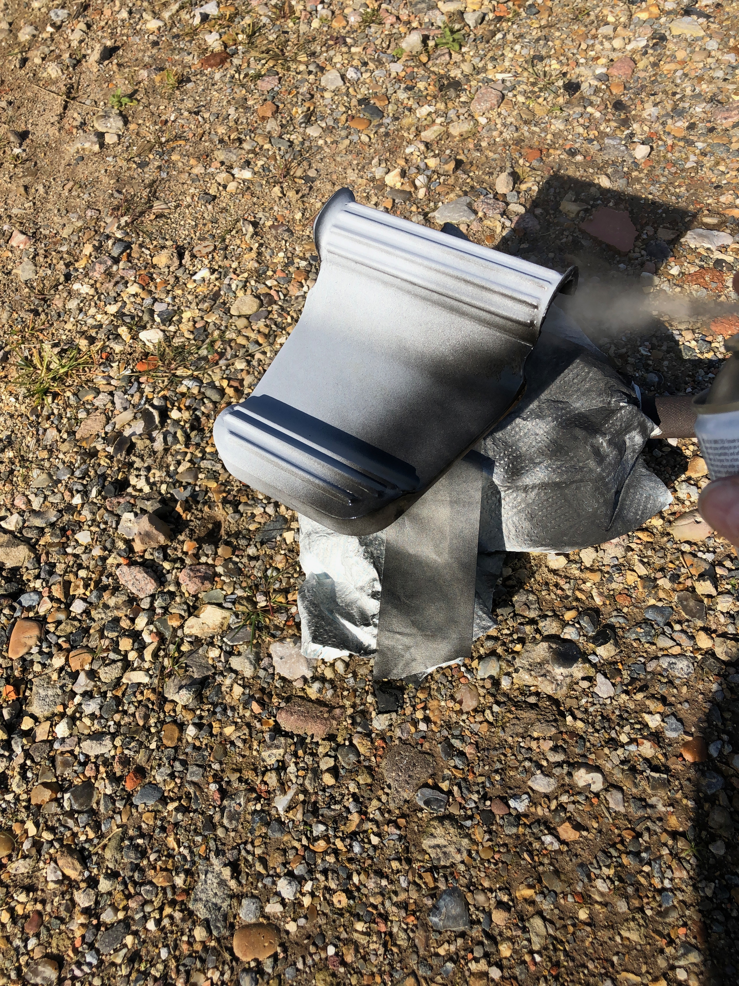
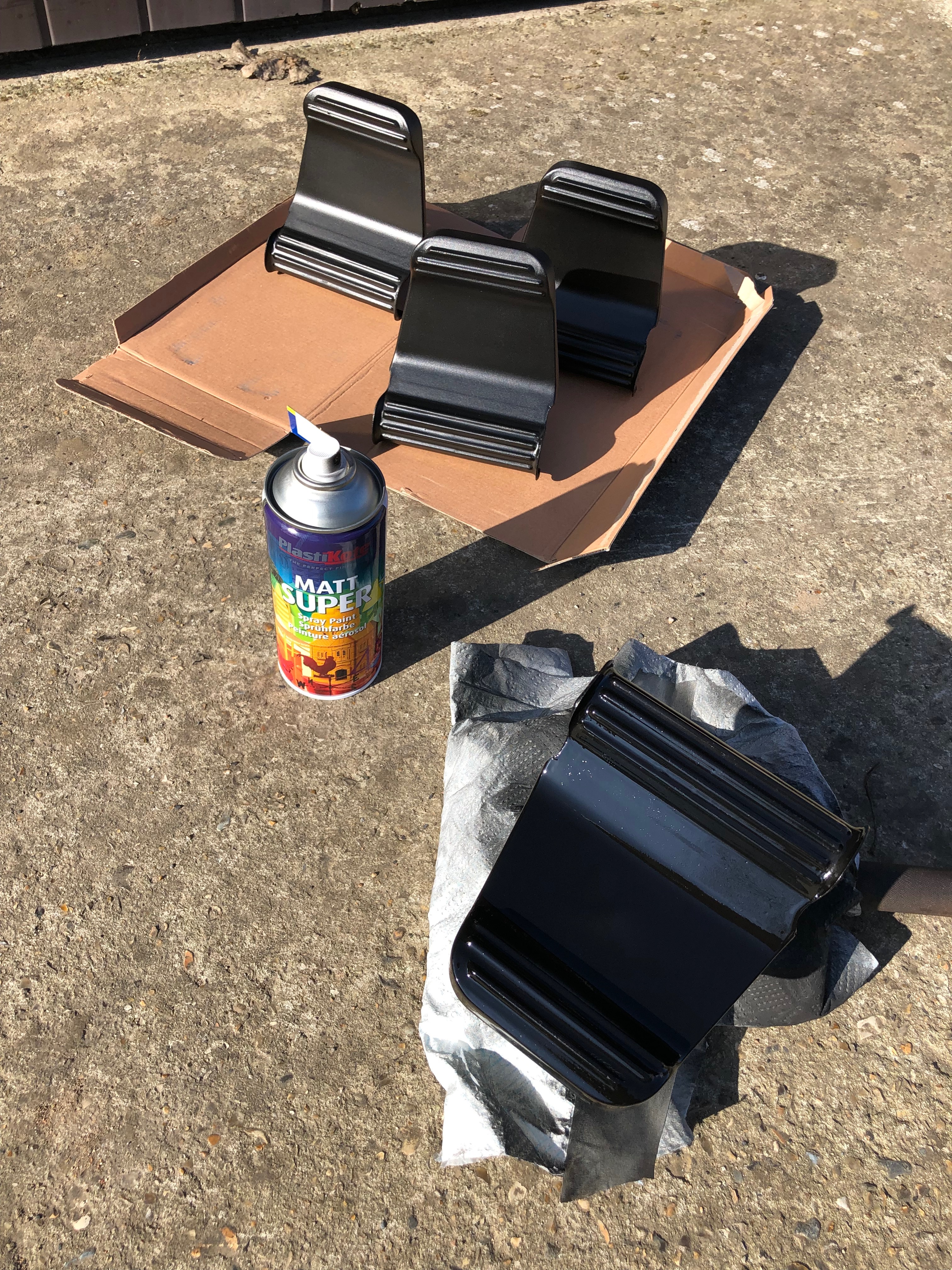
One of the jobs I can do between other jobs is to paint the rudder pedals. Two coats are needed leaving then to dry for about an hour between coats.
Last coat applied and drying off in the sun.
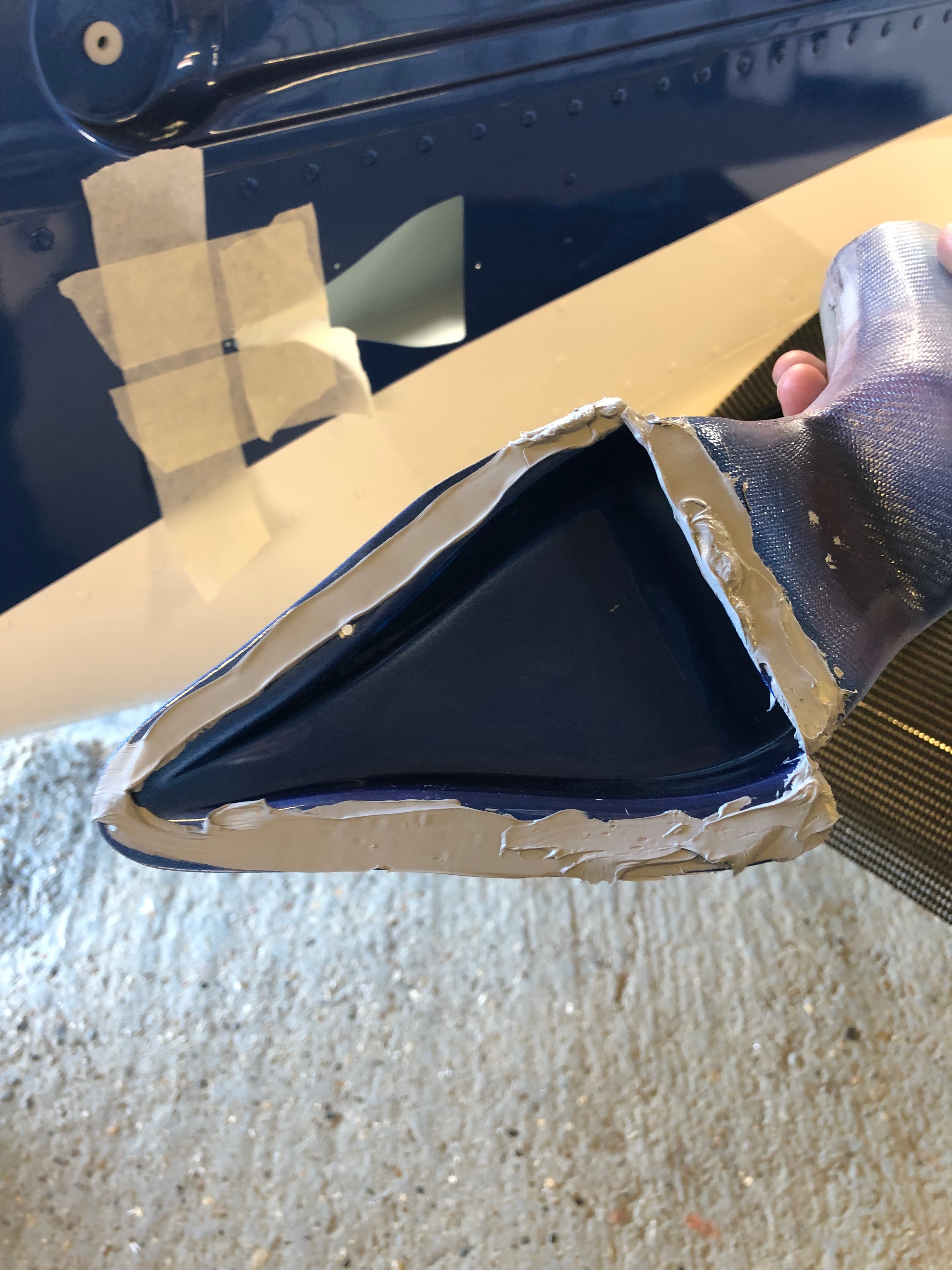
I had already drilled the NACA ducts but the mastic to seal them was too cold to apply so I had to warm it up slightly to apply it.
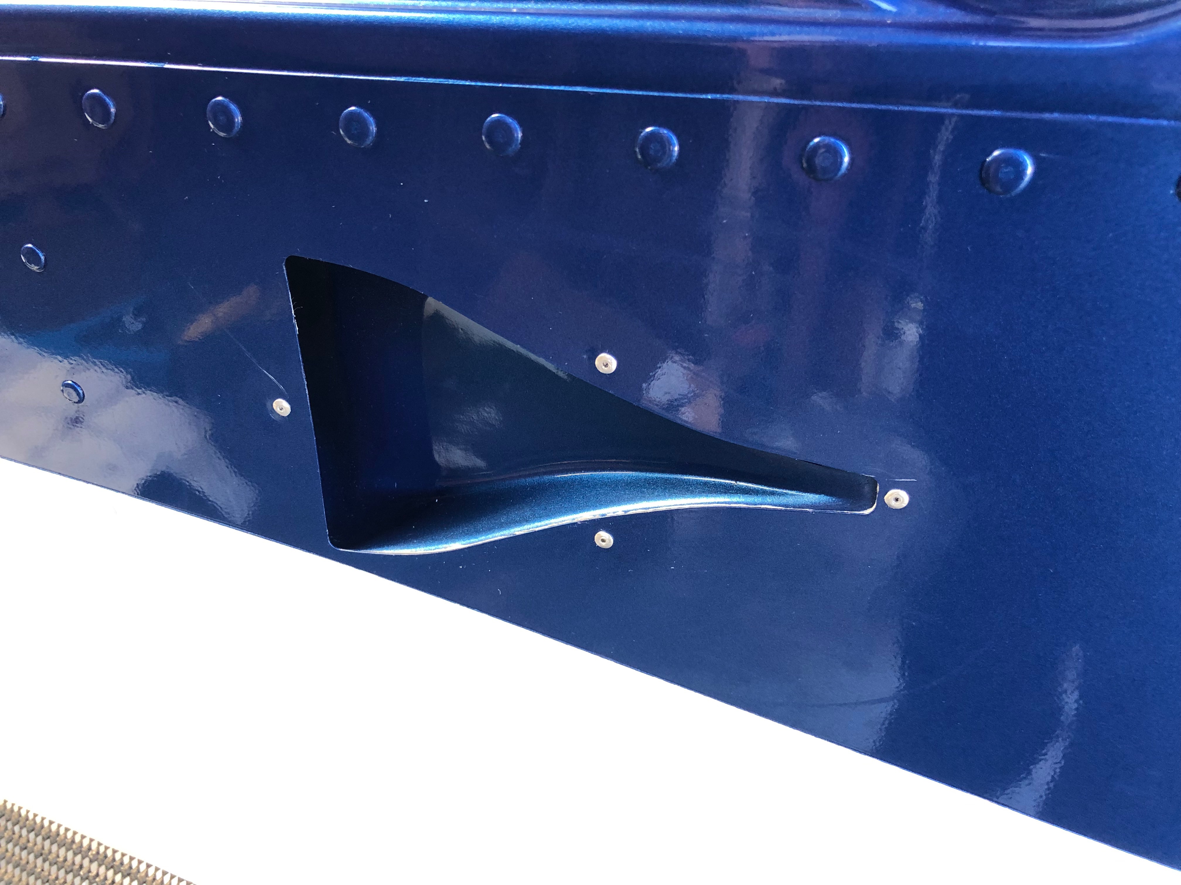
When I riveted the right side NACA duct I slipped twice and scratched the paintwork slightly which will need touching up and polishing out at some point. To stop this happening again I applied some asking tape around the rivet.
Right side duct. As you can see a slight scratch on the left rivet.
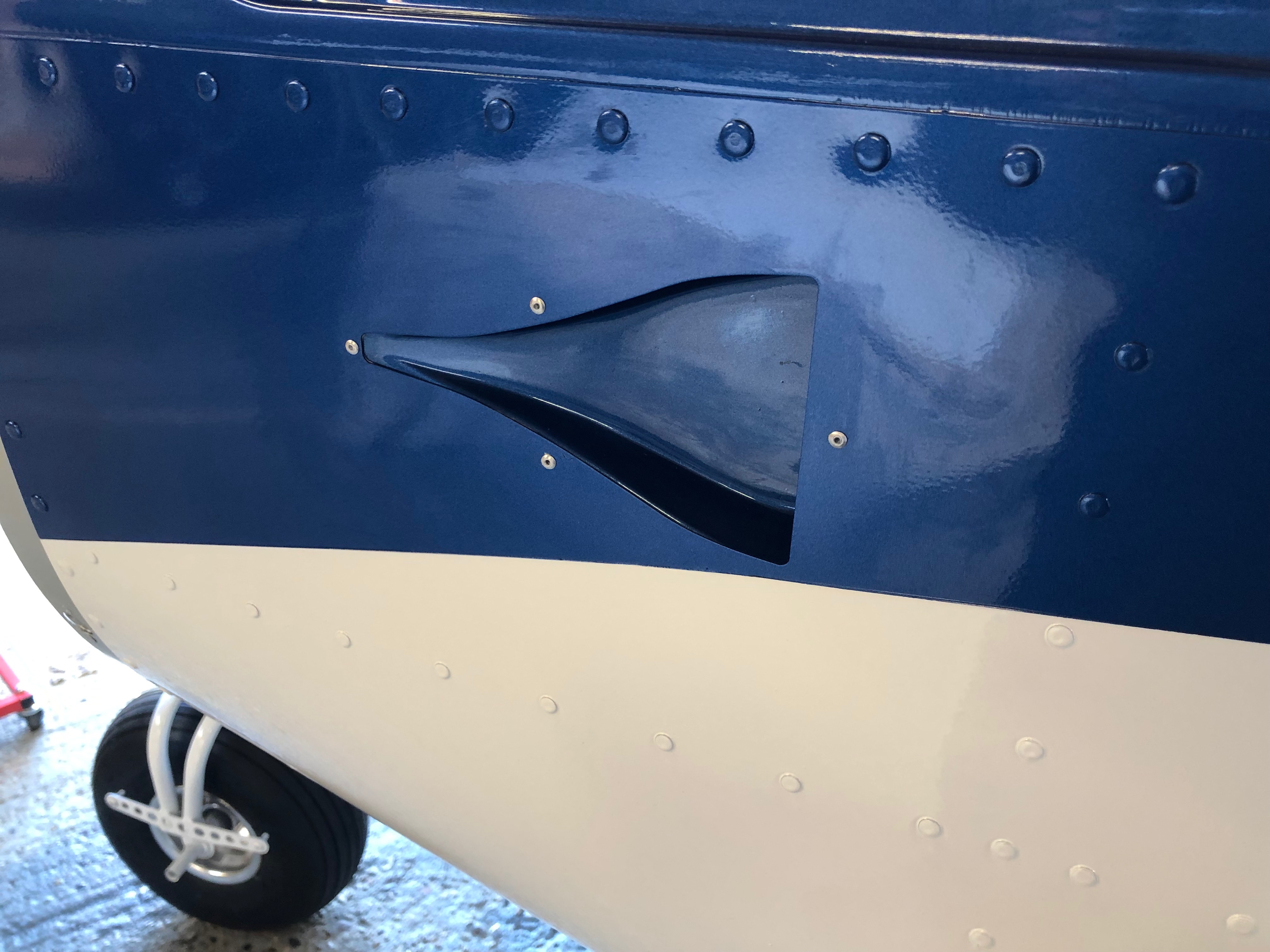
and the lefthand duct. A better job on this side. The duct install is now complete but still needs the Scat hose to be added for the cabin air vents.
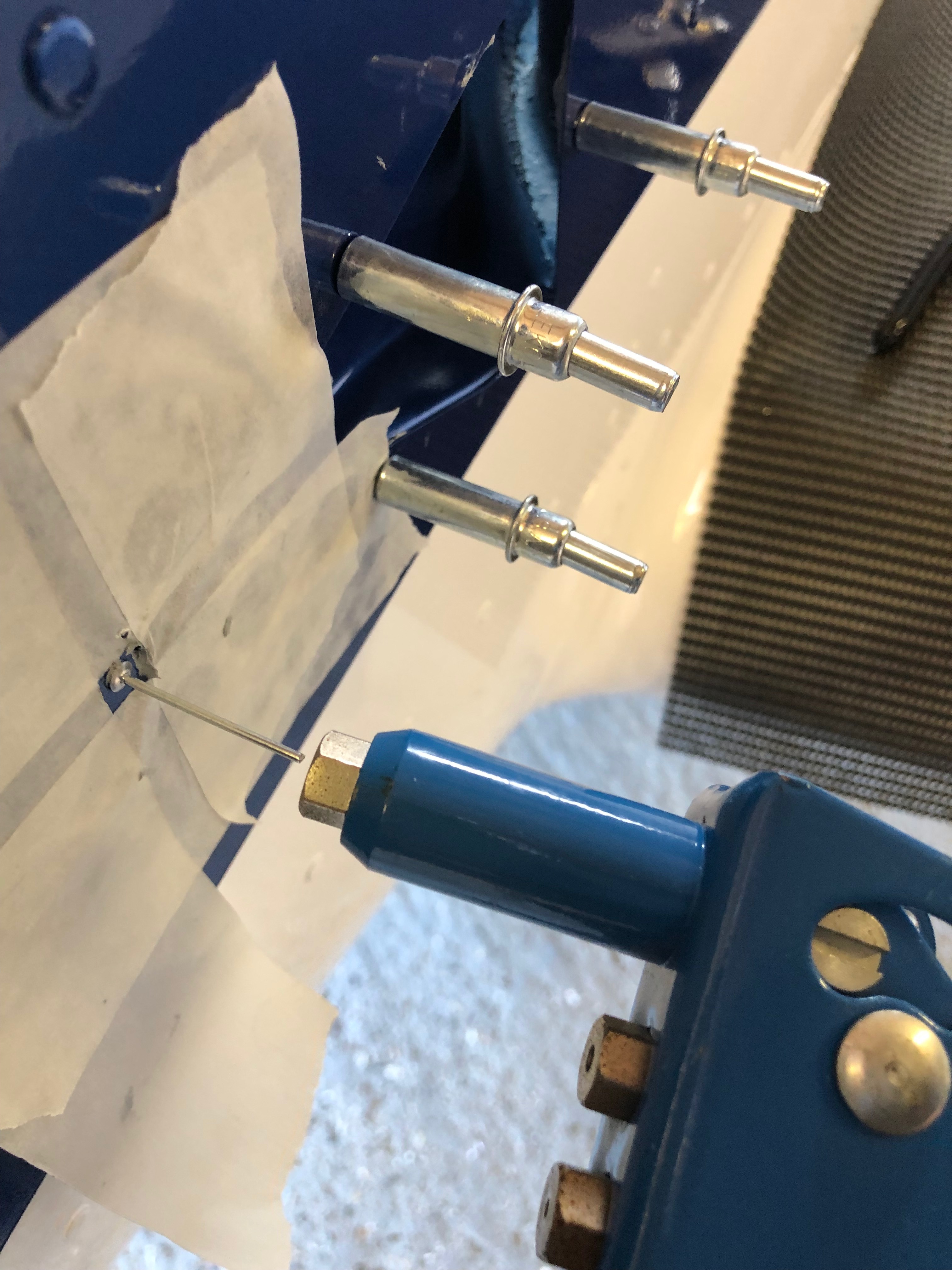
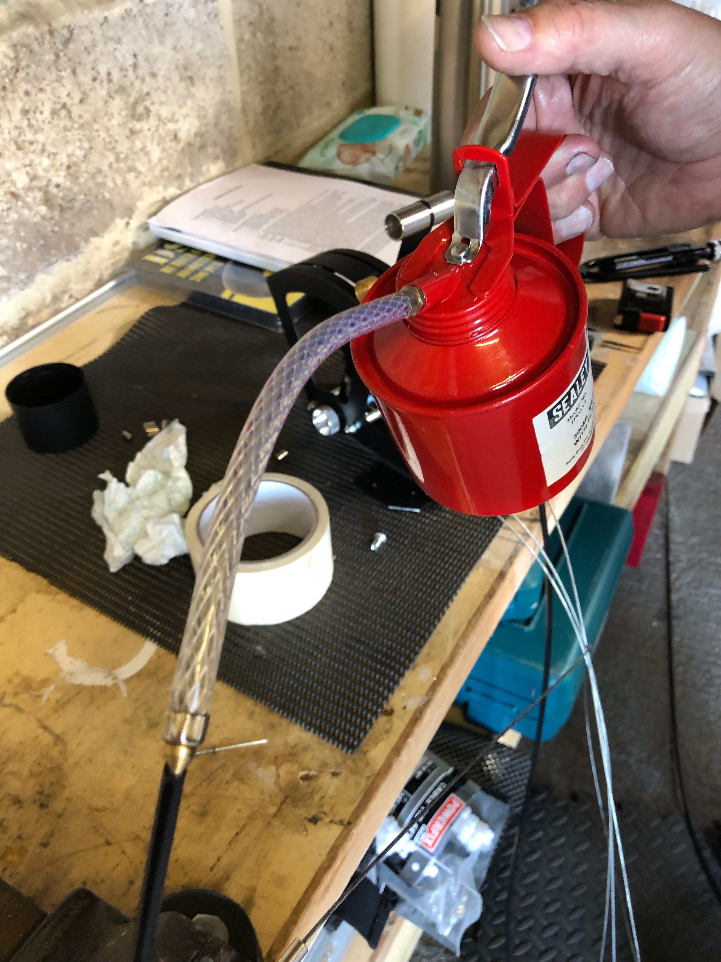
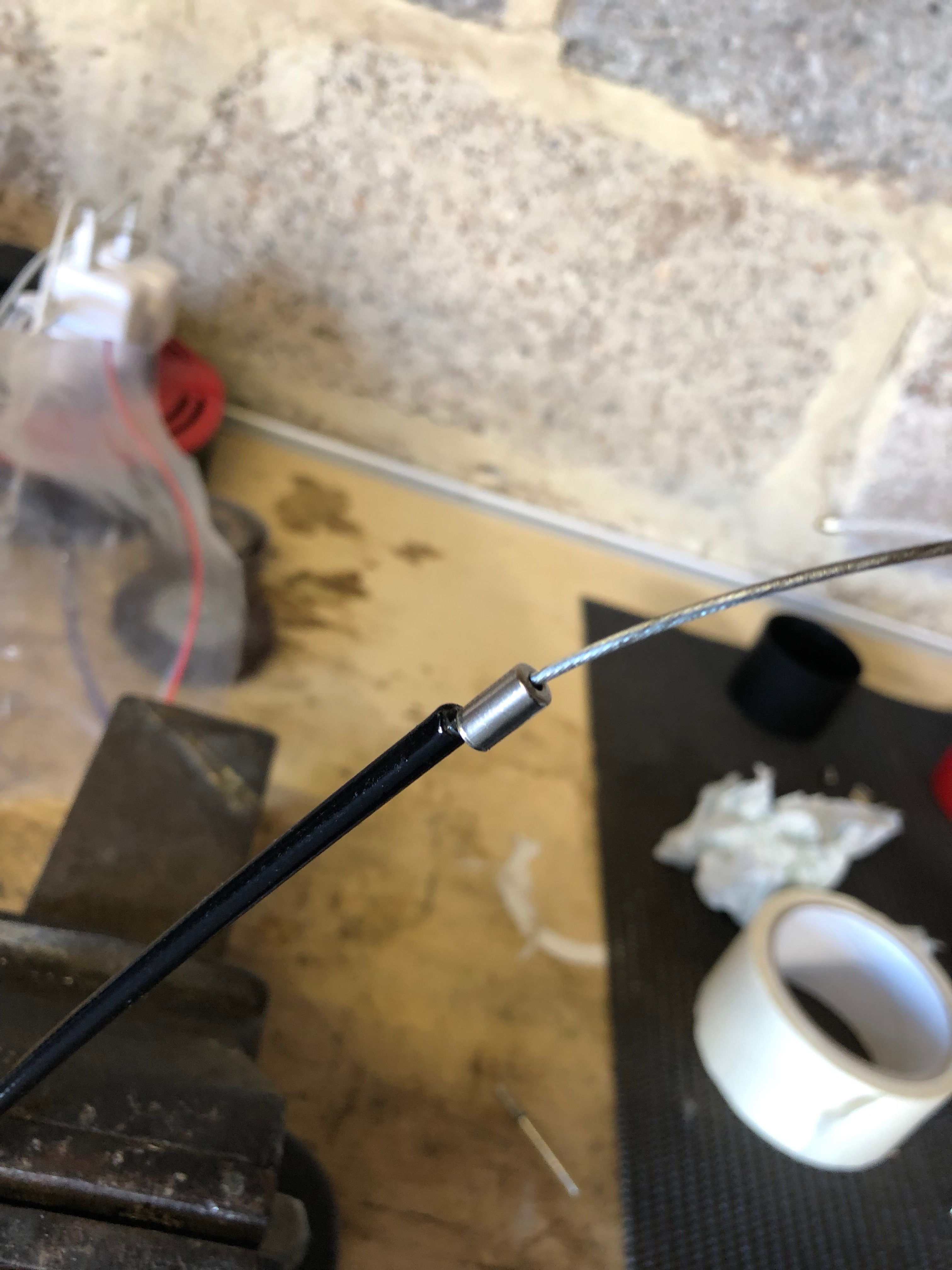
The throttle cables have to be cut and made up. A few drops of oil down the outer will allow the cable to run smoothly and operate better in service.
Ferrules are added to the outers before fitting.
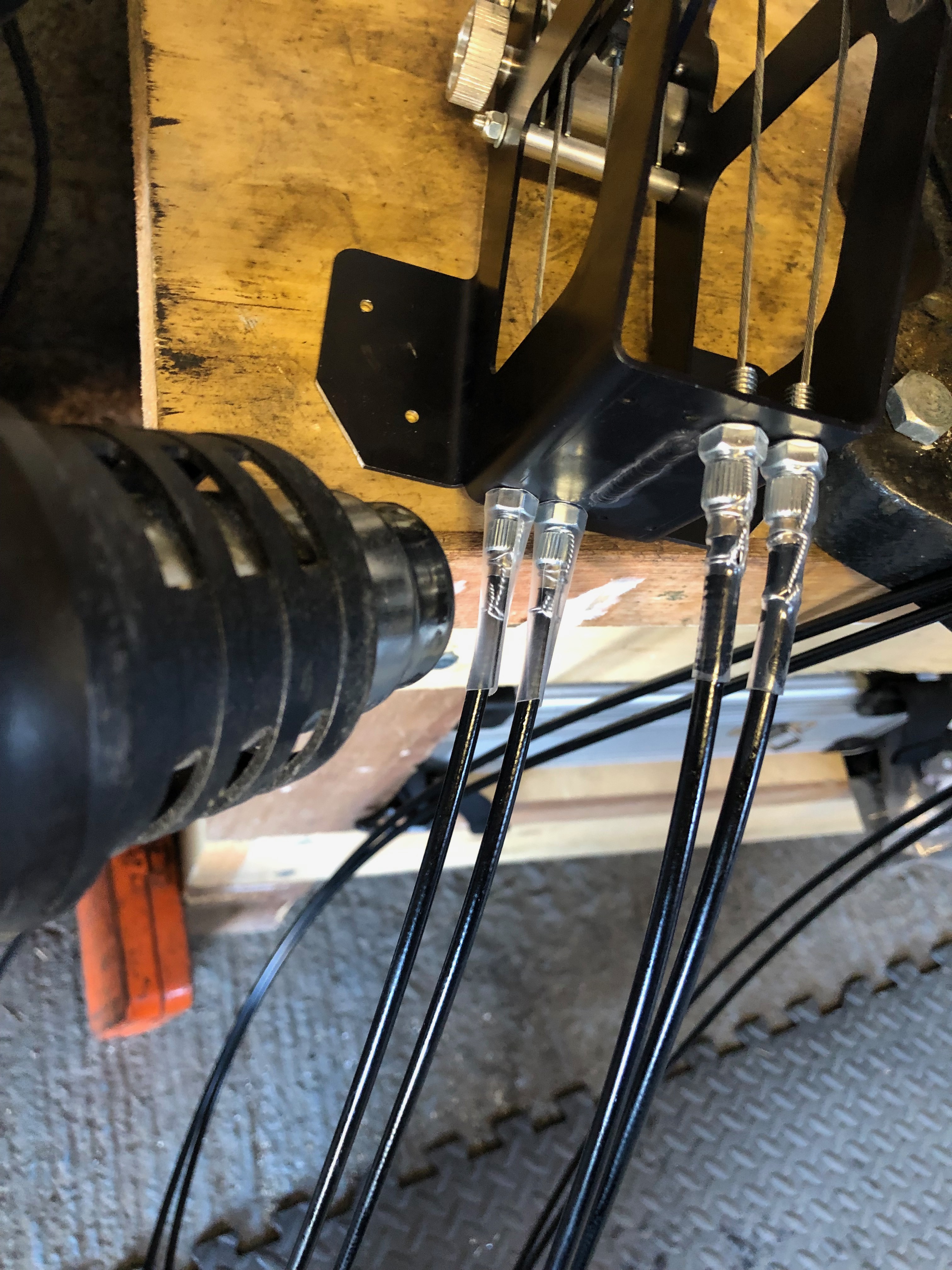
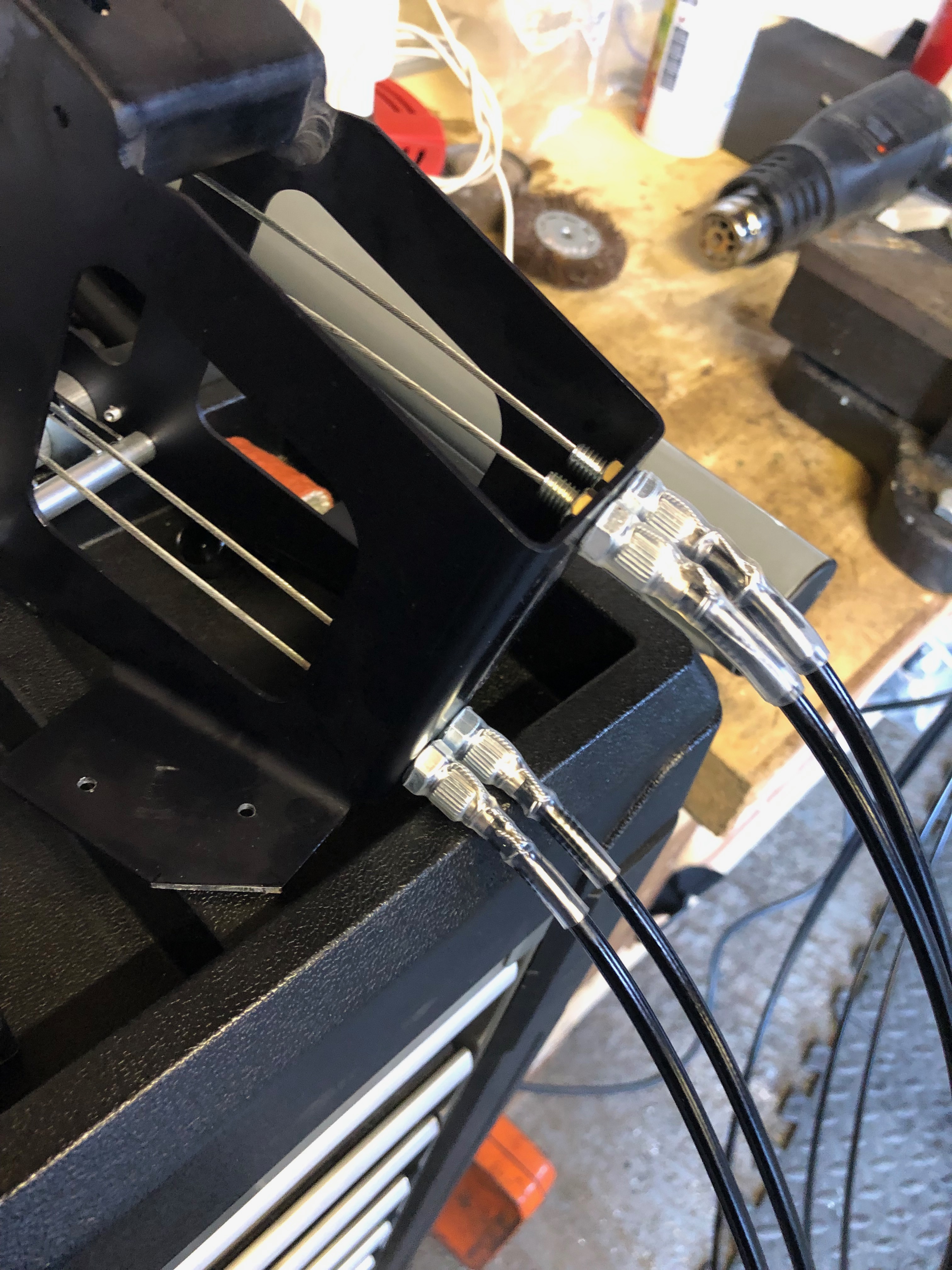
Wire locking is added and a piece of heat shrink tubing is slipped over the assembly to ensure is doesn’t undo.
The throttle quadrant is complete and will be installed when I come back this evening.
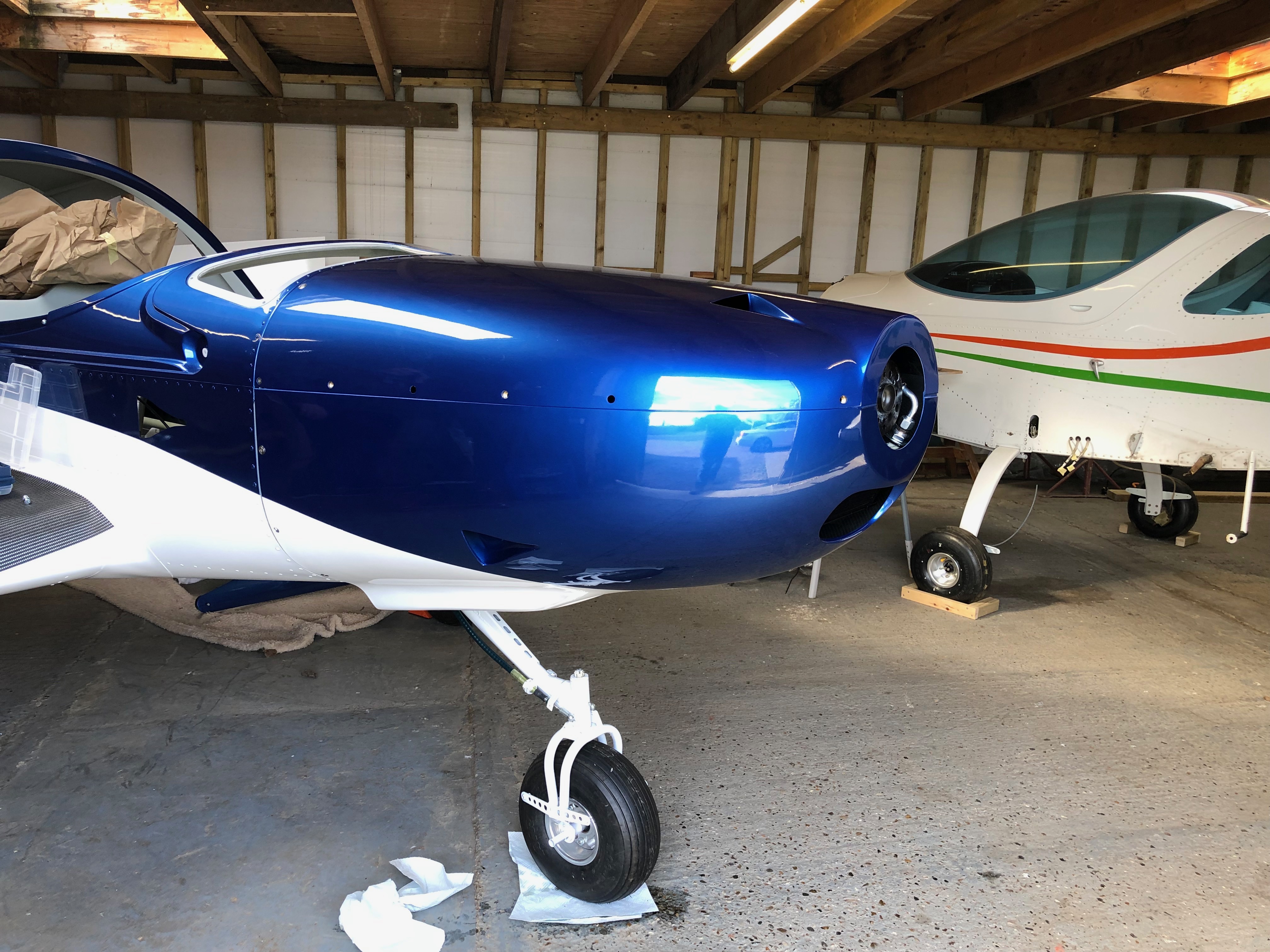
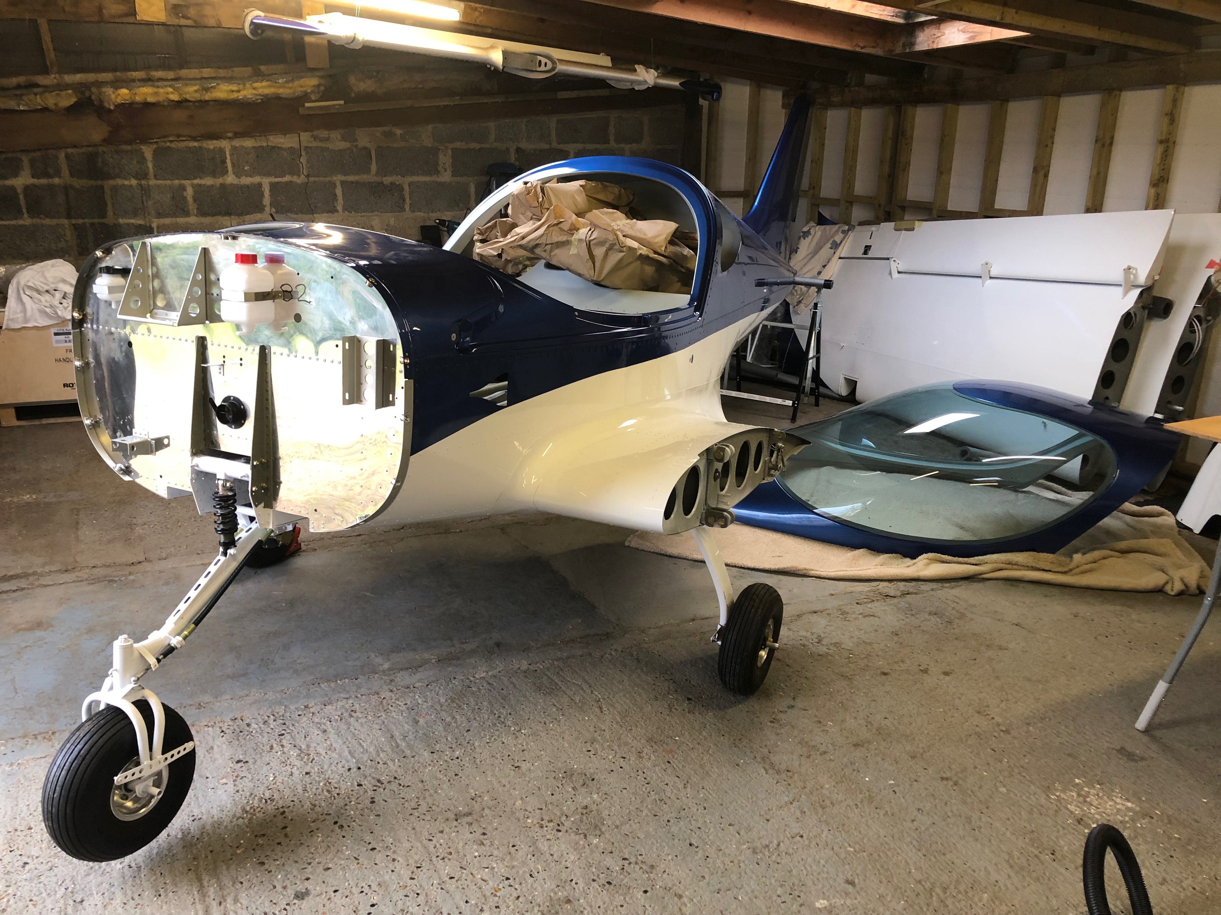
After fitting the fuel, oil and hose systems it’s time to see if the cowls fit properly around the radiators. It’s a two person job so Karen has come to help me this morning.
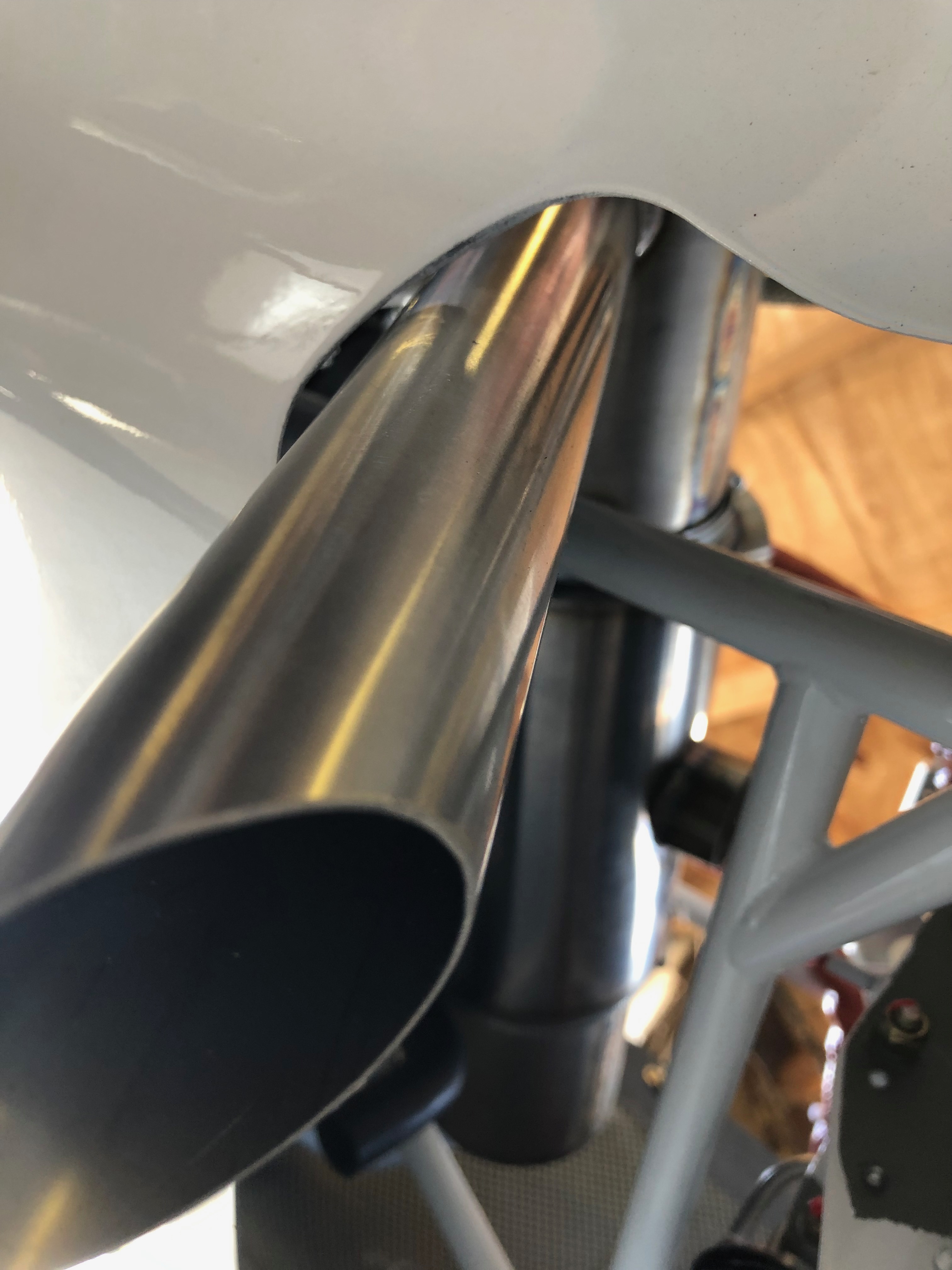
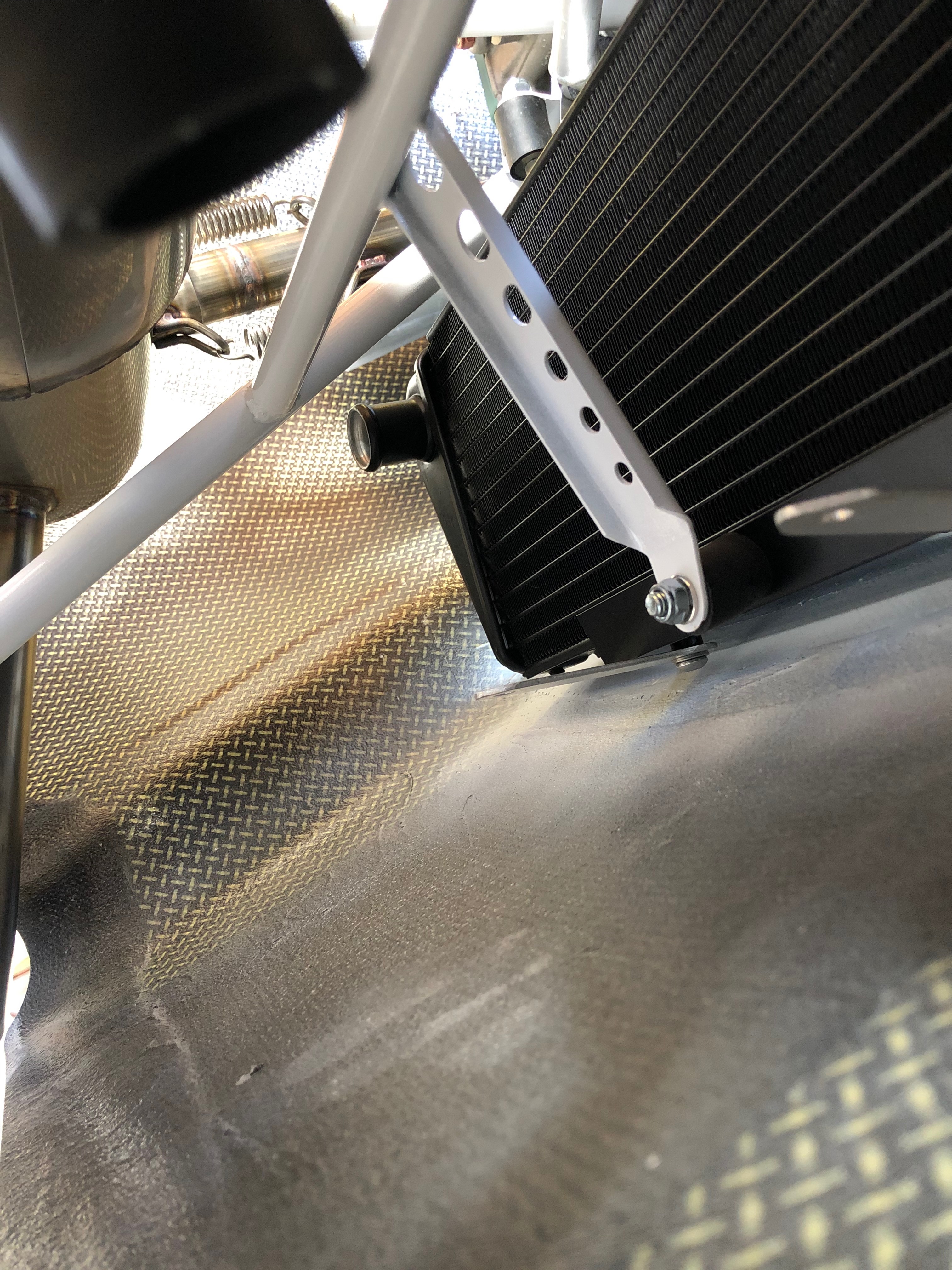
Exhaust pipe is very close but the clearance should be ok.
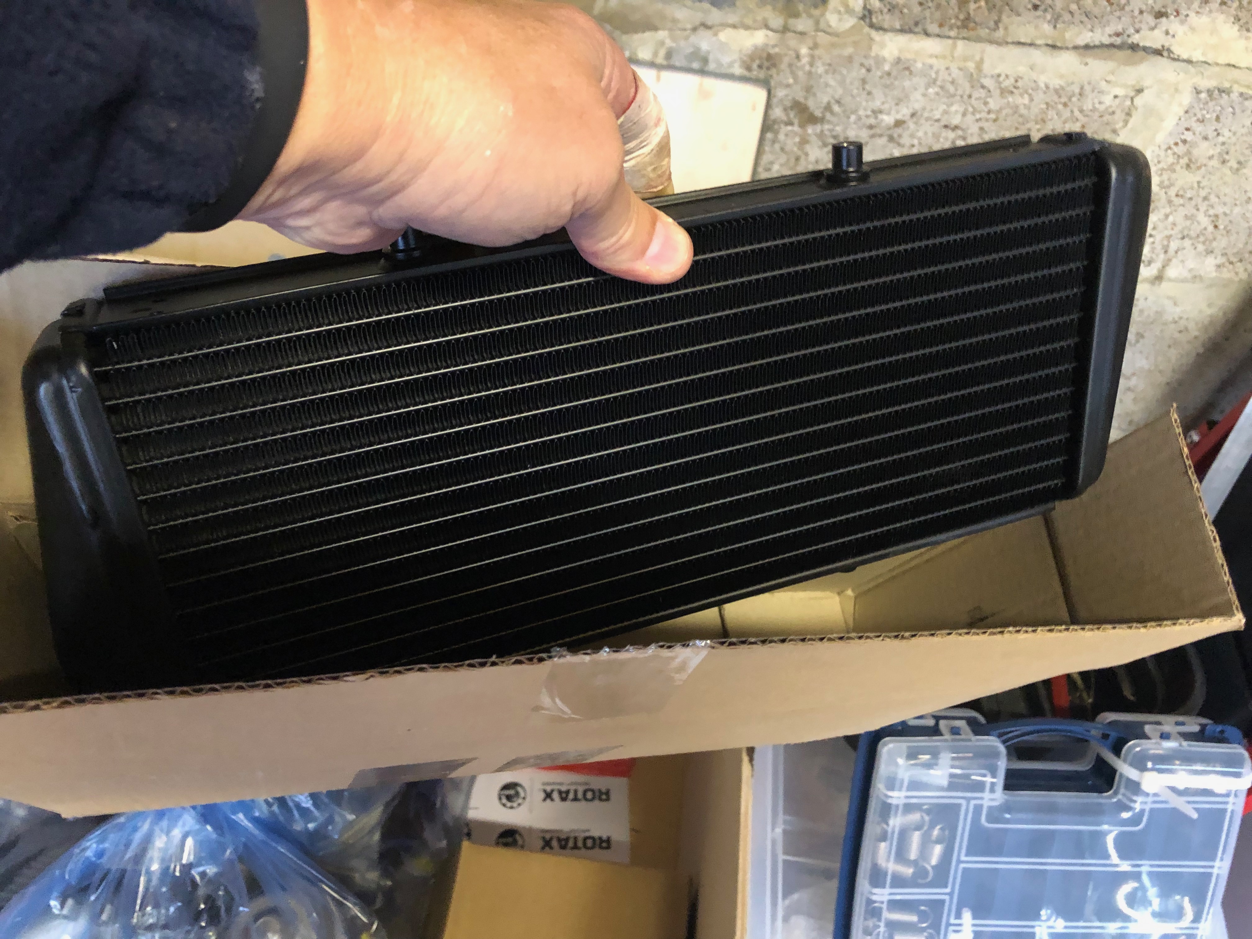
However the water radiator is too tight so the position and cowl will need to altered.
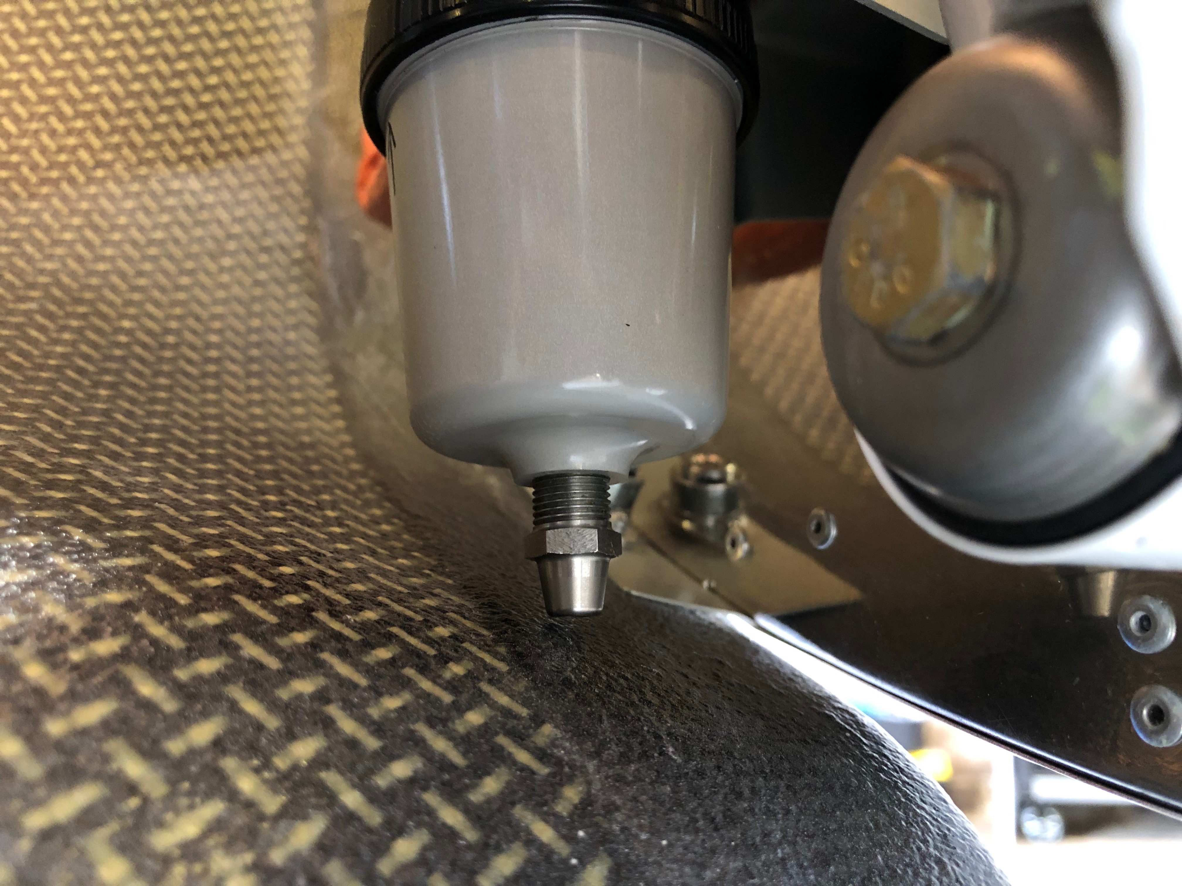
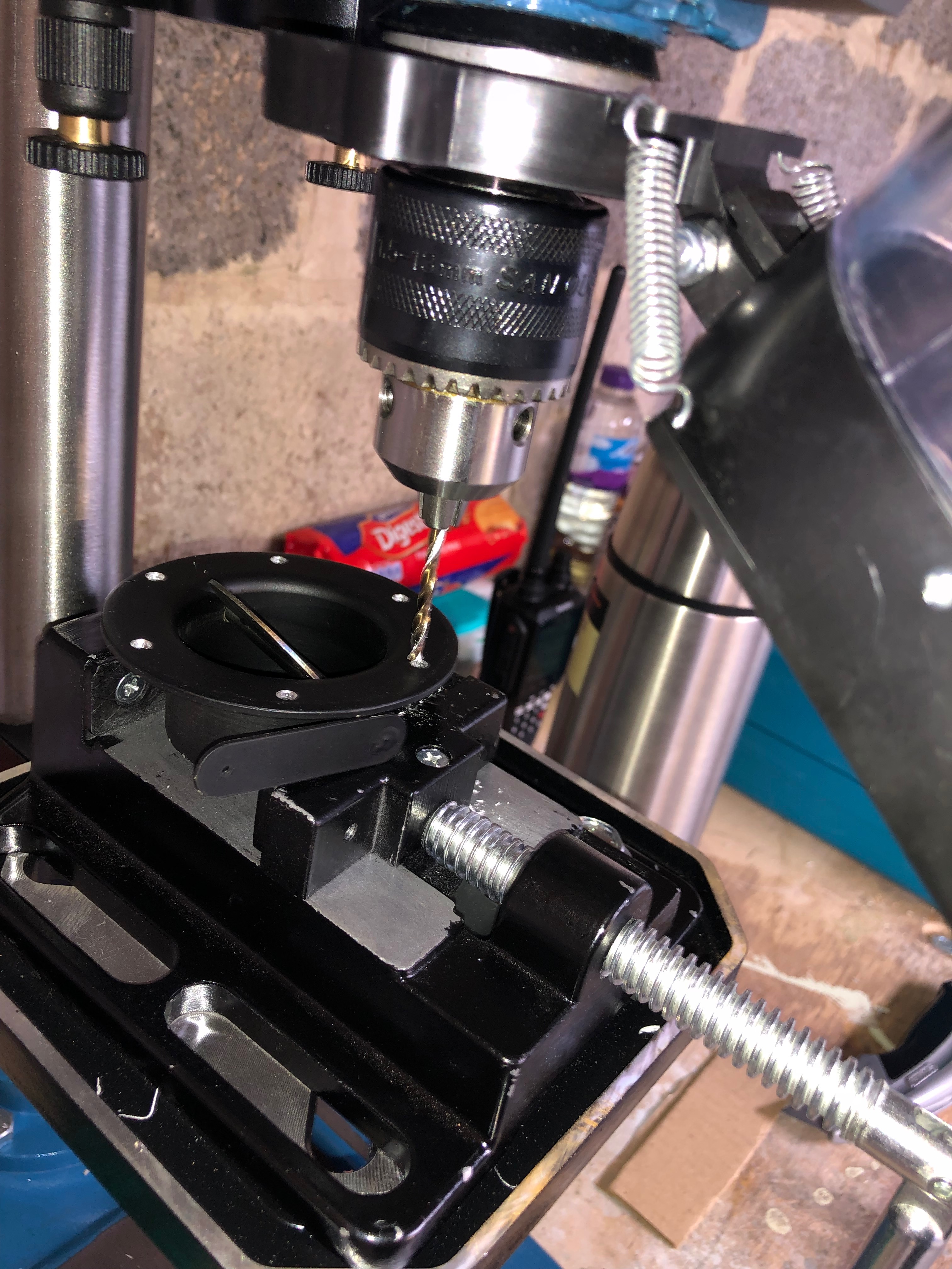
I will need to drill a hole for the fuel drain so I can check the fuel before each flight.
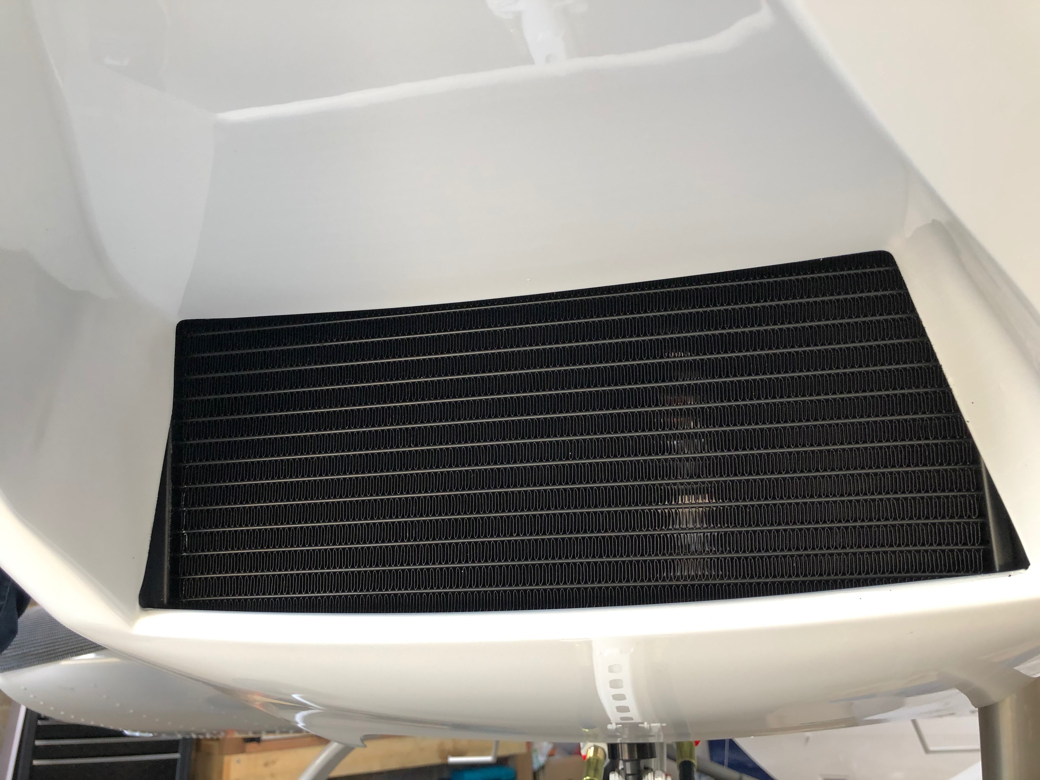
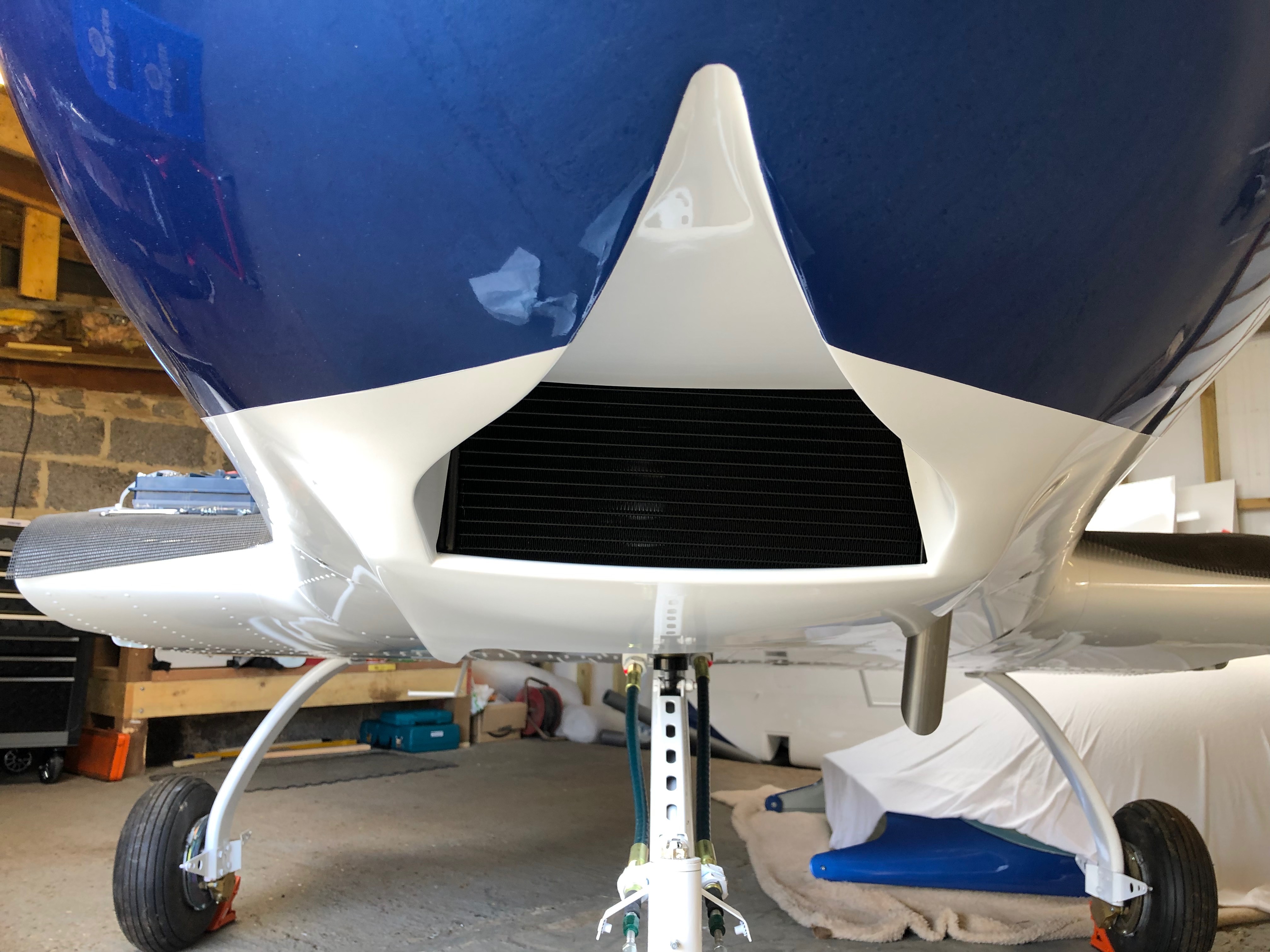
From the front the water radiator looks fine.
From the rear, the radiator brackets disconnected to allow movement for the trial fit.
The cowls fit but again only with the radiator brackets disconnected
Underneath looks fine.
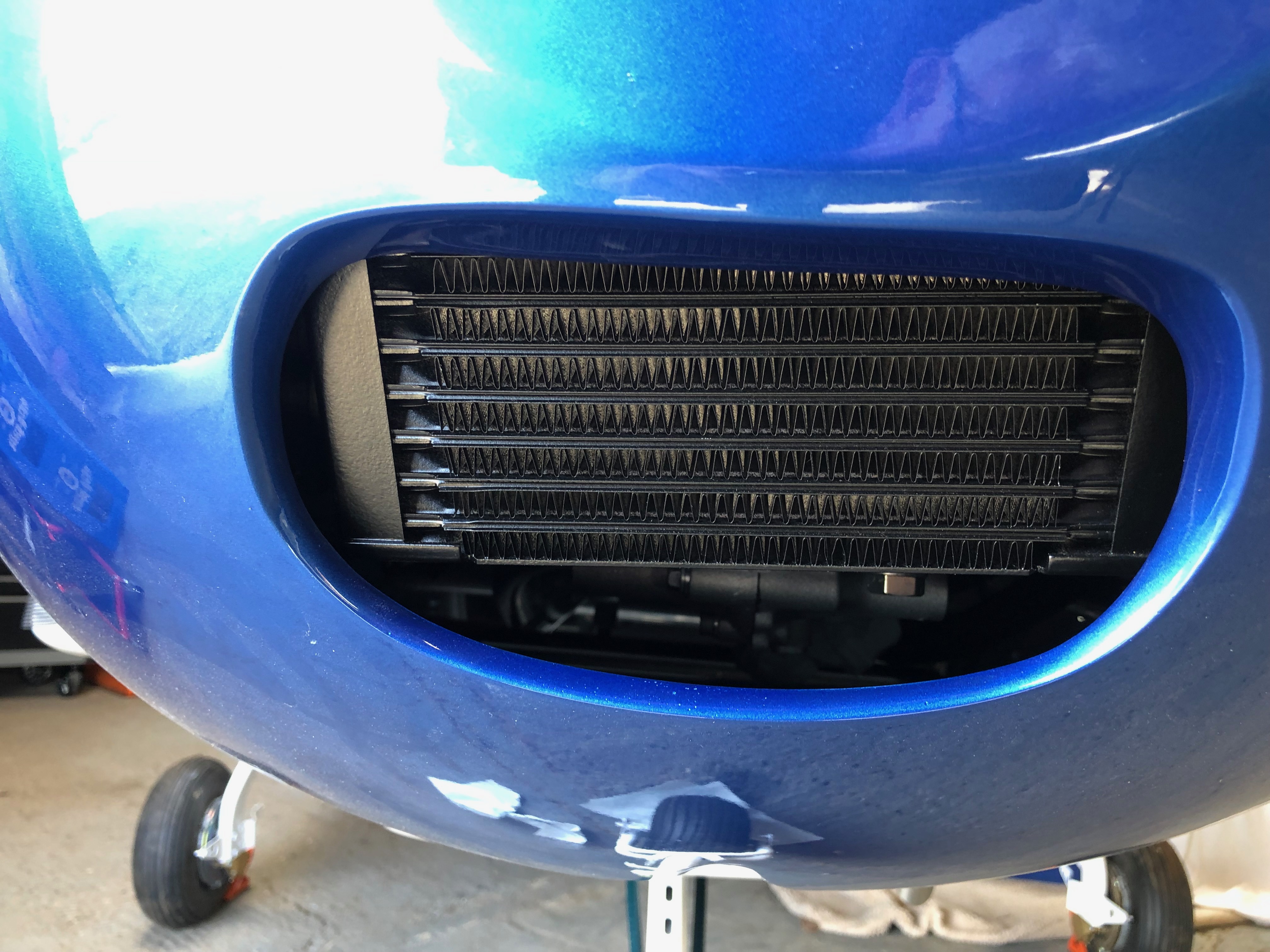
The oil radiator fits fine with a slight adjustment to its position.
All seems to be centrally located.
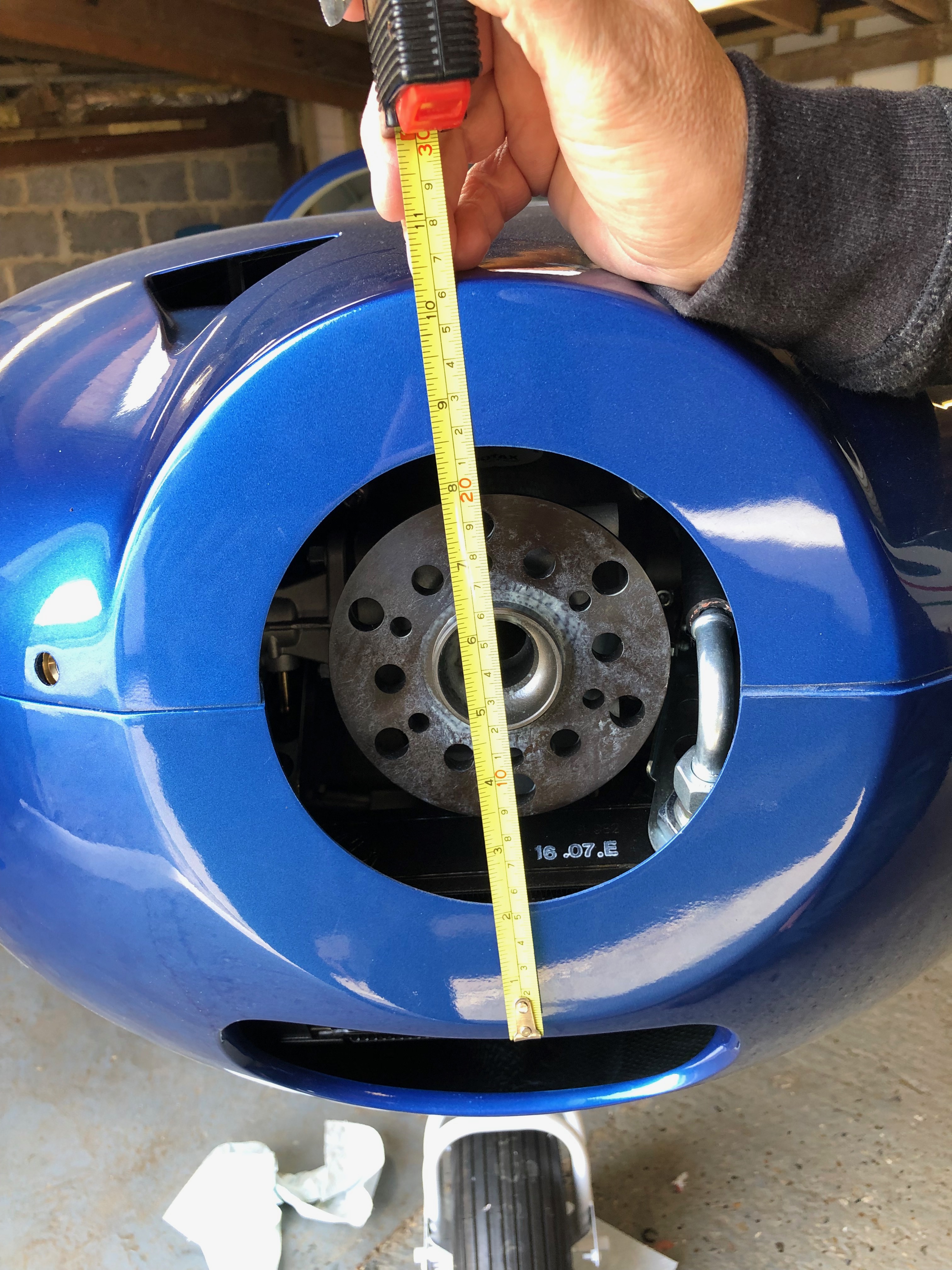
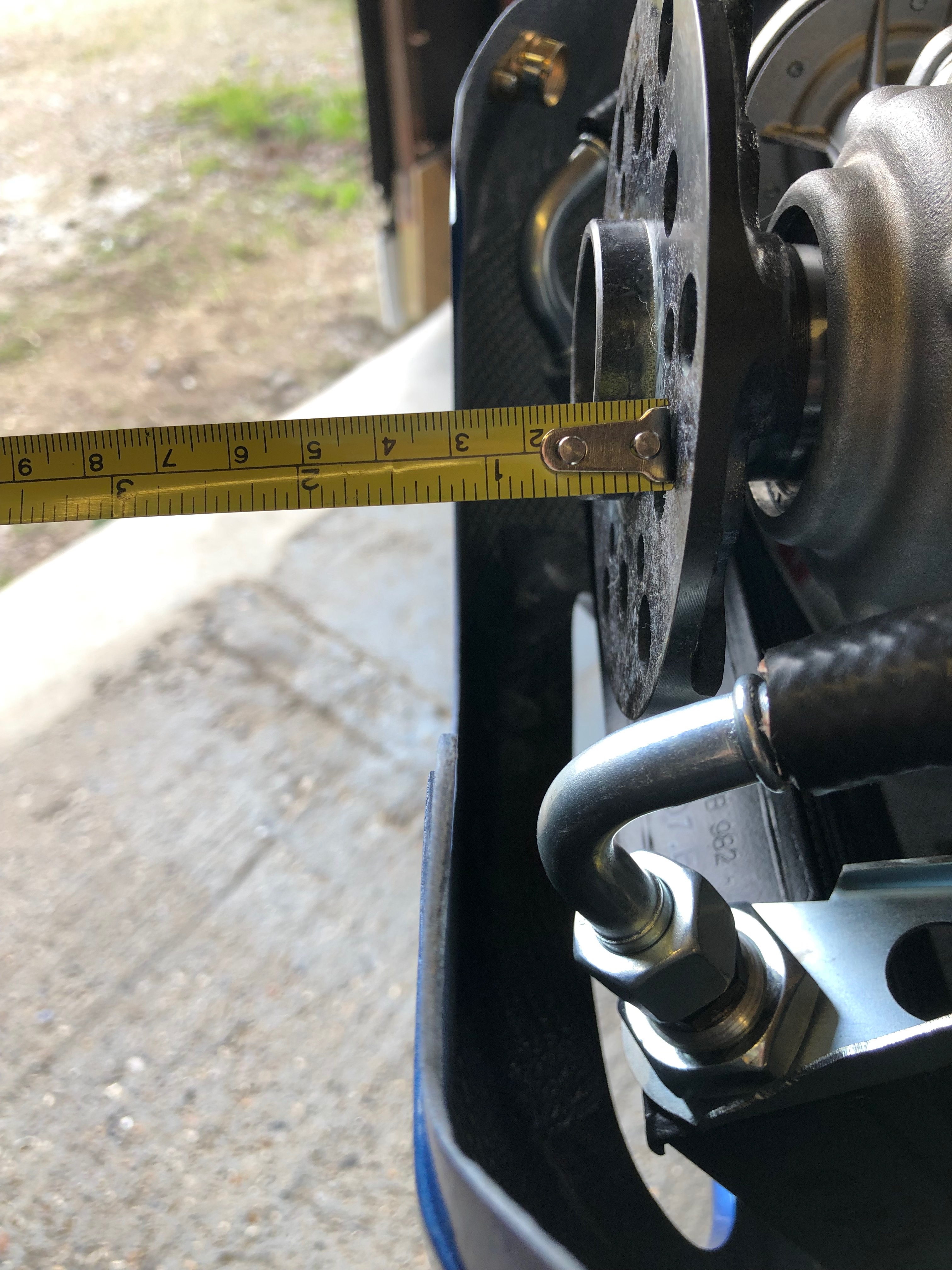
Need to measure the front of the cowl for the spinner size.
And the distance from the engine flange plate to the cowl. This allows a calculation to be done for the prop extension that needs to be fitted.
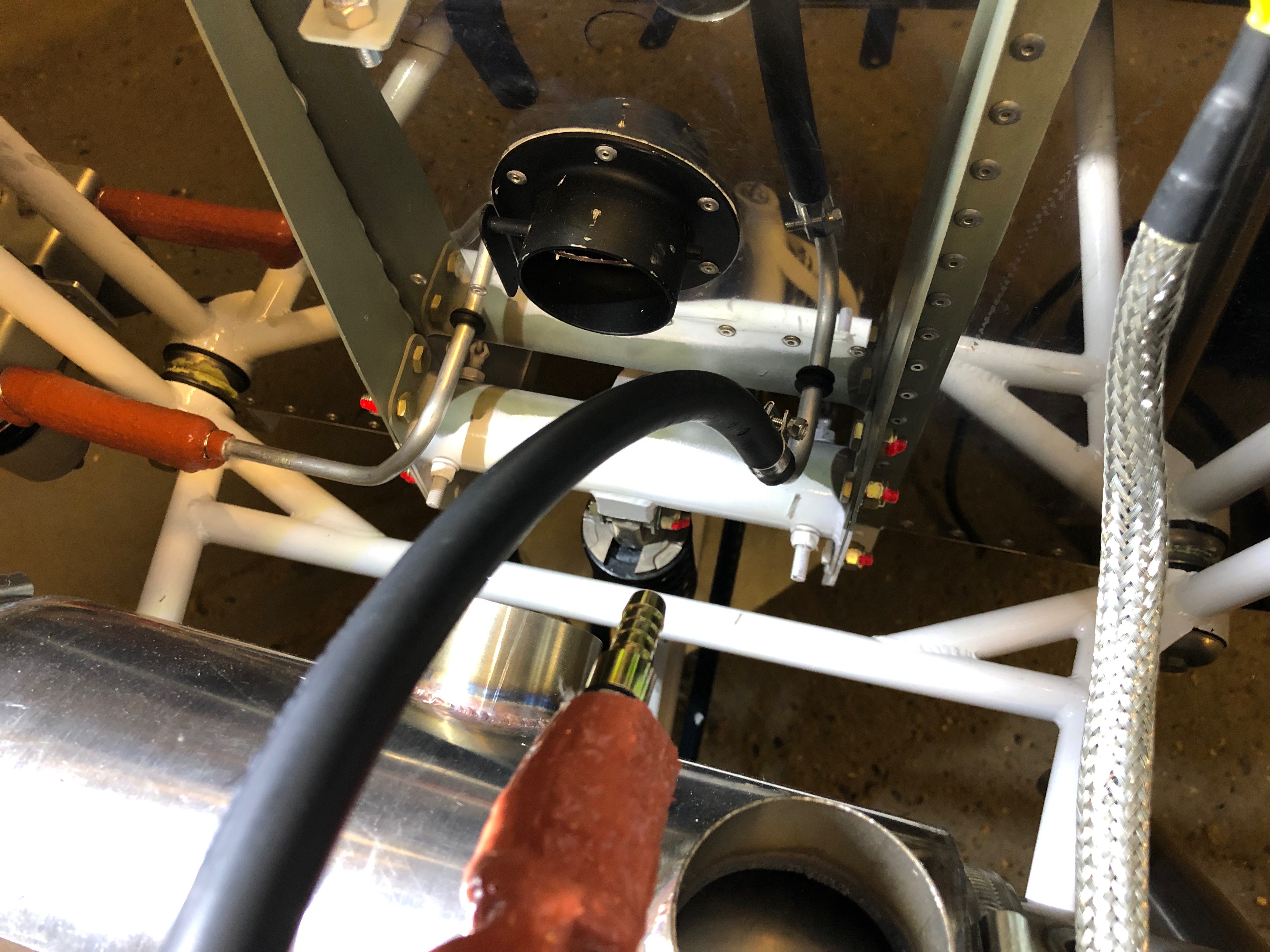
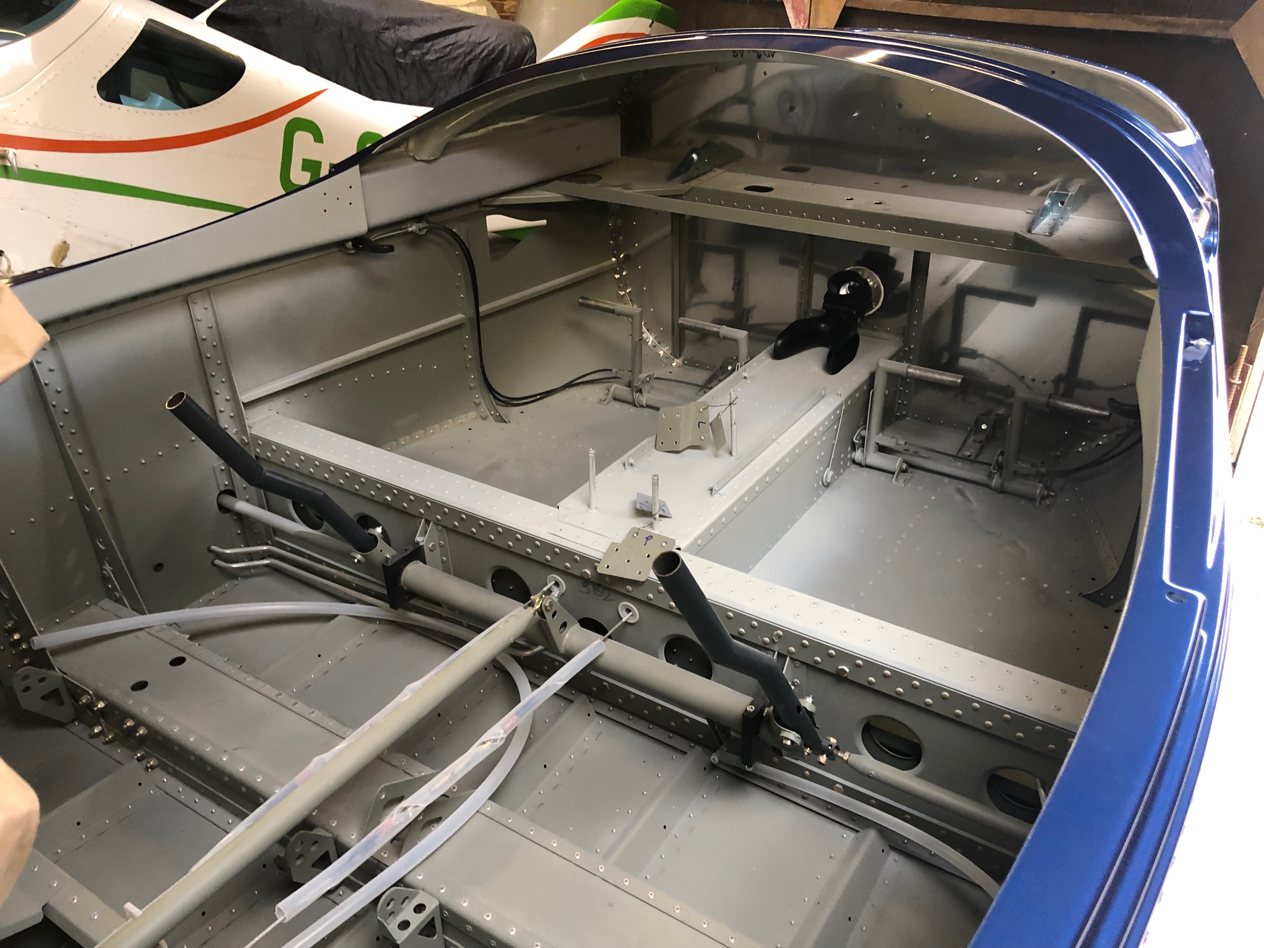
The fuel pipes each need to be bent 45 degrees to accept the connection pipes from the fuel selector.
I had a number of things planned to do tonight which included installing the reducing connector on the return line, bending the fuel pipes in the cockpit to accept the pipes from the fuel selector, applying Loctite to the oil radiator bracket and mount bolts and fitting the NACA air ducts.
First up is bend the fuel pipes using a pipe bender. Got to be careful that I don’t bend the pipes too far as it’ll be virtually impossible to bend them back. Luckily it has an angle guide to help.
All three pipes now bent as required. It was easier than I expected apart from the pipe on the right which was impeded by the adjacent bracket.
Onto the the fuel return line. First job is to cut the pipe and insert the reducer.
The return line is 6mm i.d. so the reducer converts from 6mm to 8mm so it can be connected to the 8mm aluminium return line.
Clamps and a new section of fire sleeving is slid over the pipe and wire locked together and at the end.
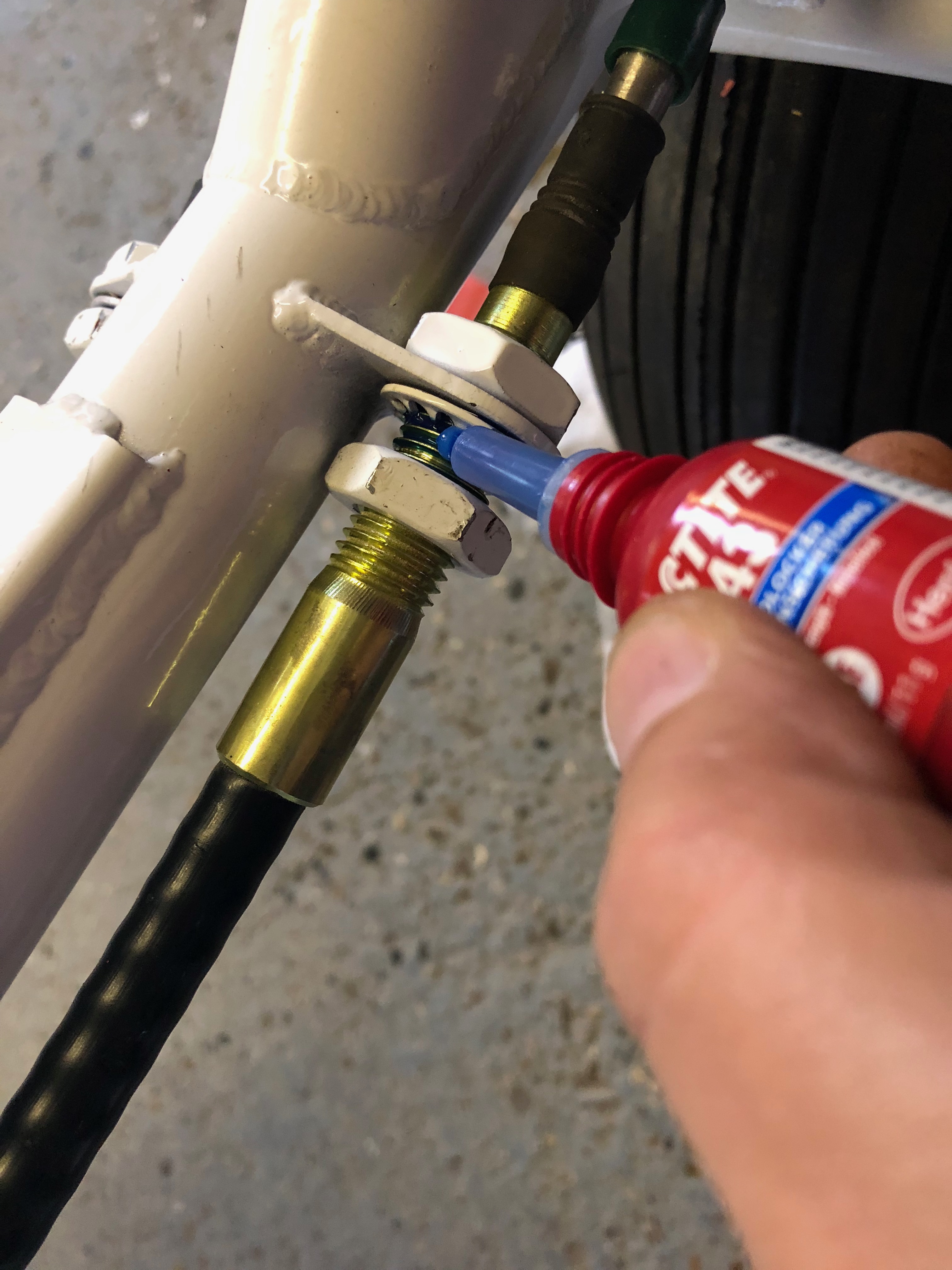
Loctite 243 is applied to the oil radiator threads and the bolts are tightened immediately.
Loctite is also added to the threads of the oil radiator bolts that hold it to the engine.
The carburettor banjo bolts are tightened not the fuel piping is complete.
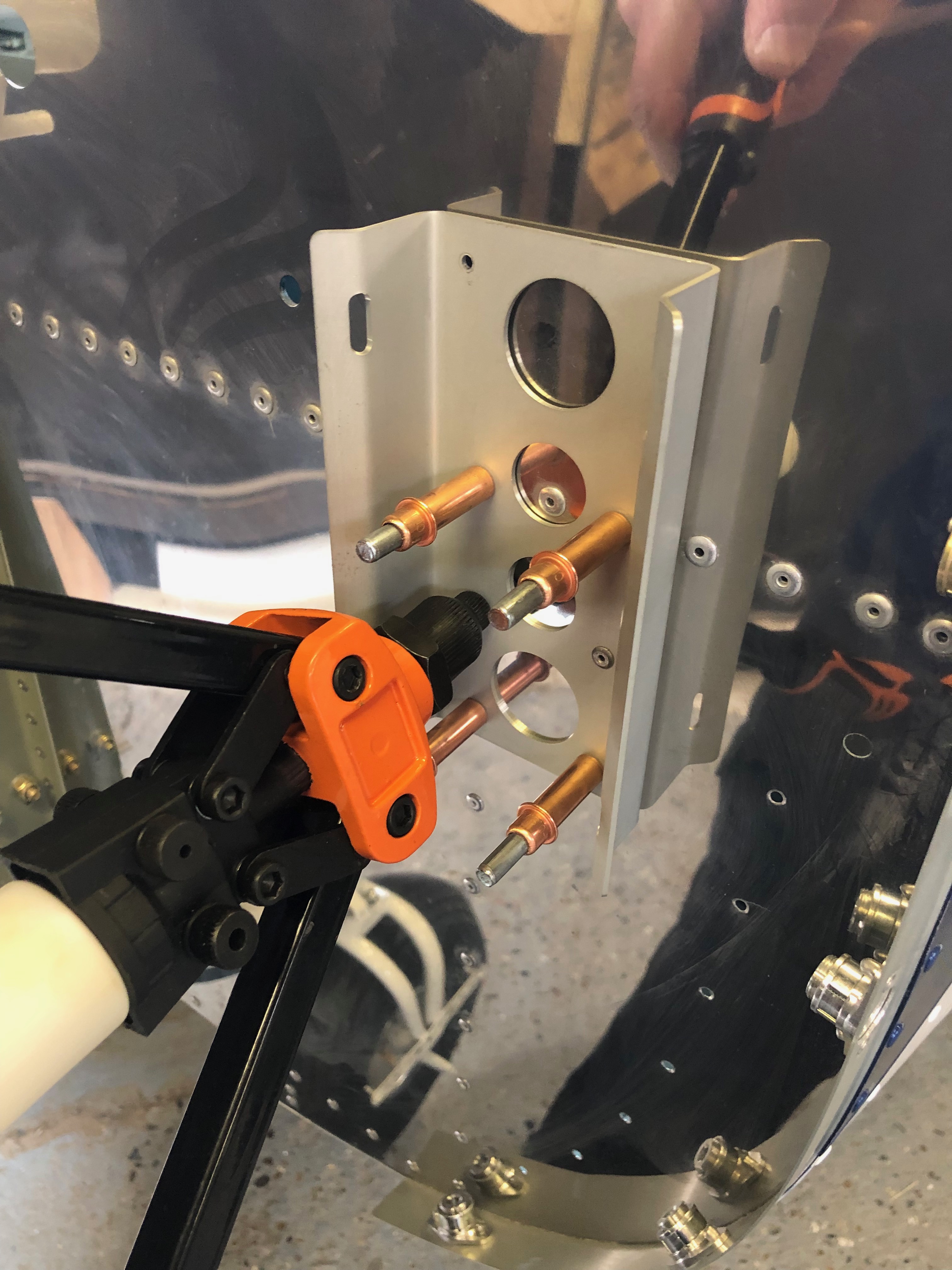
The NACA ducts are positioned and 4 x 2.5mm hole drilled to take the rivets to hold it into place.
The NACA duct in place secured by 4 temporary rivets (Clecos). The last job on this will be to add some silicon sealer to the face of the duct and rivet into place but its getting late, so time to go.
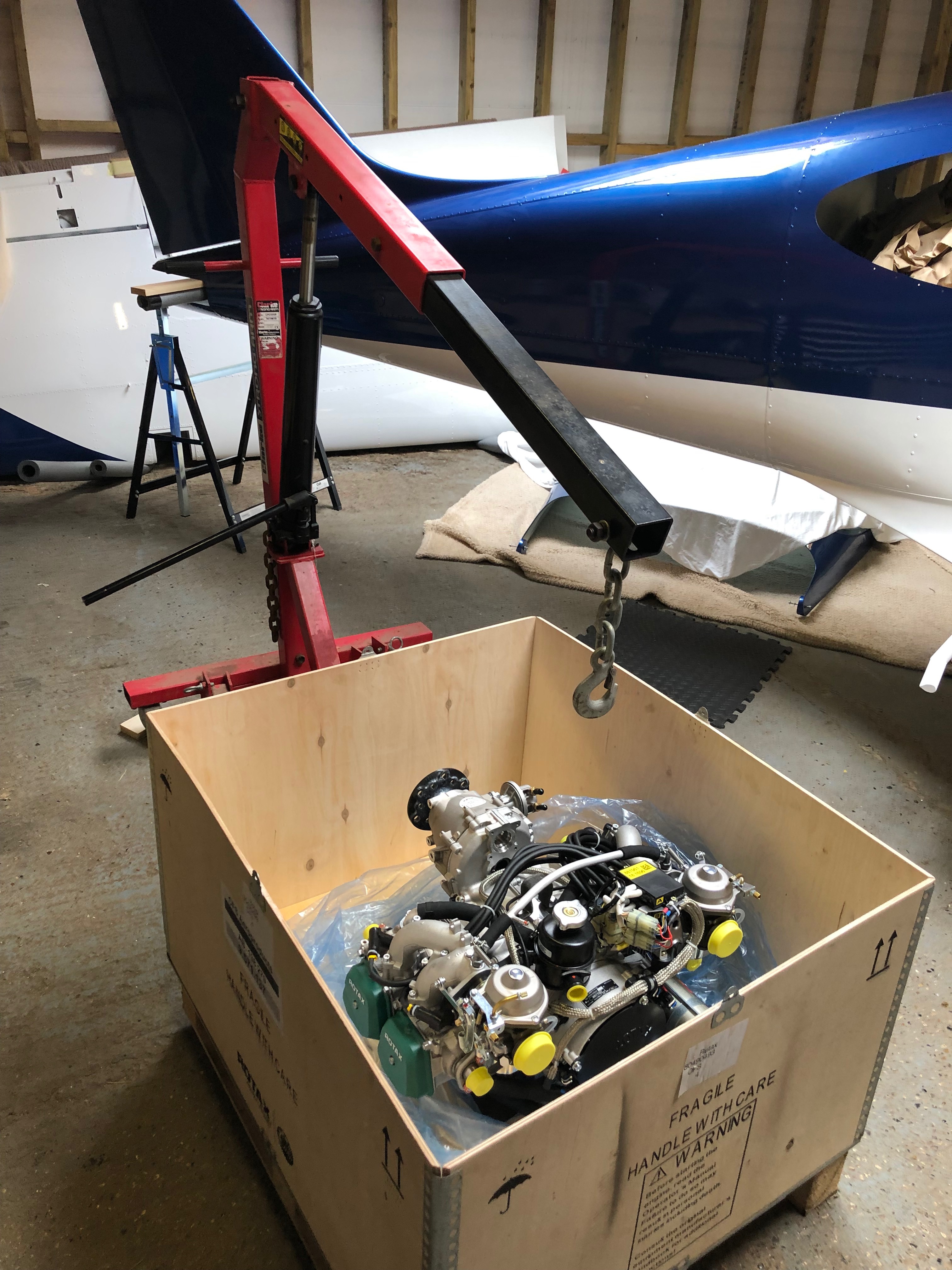
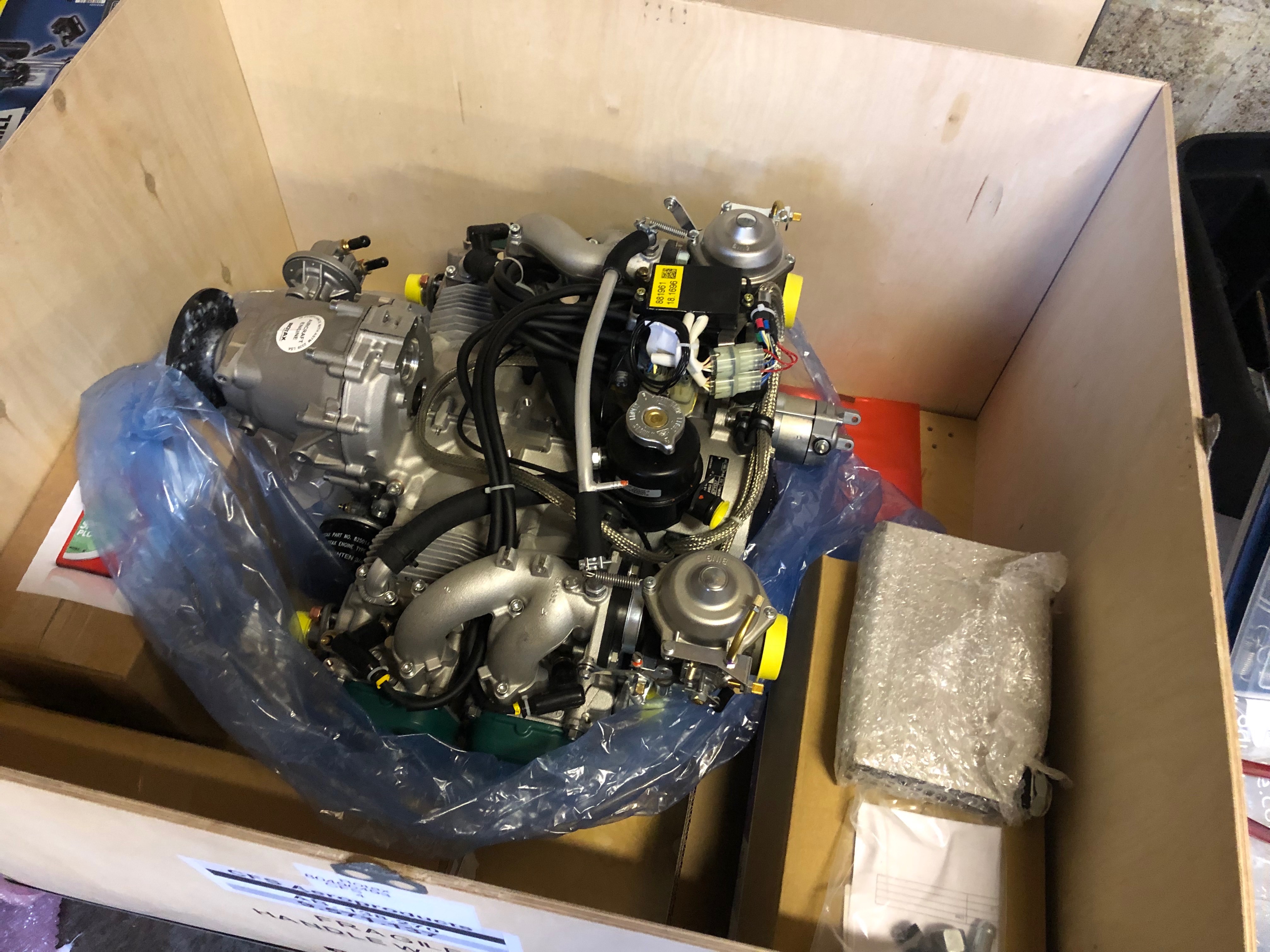
Time to lift the engine. Luckily there is an engine hoist onsite that belongs to Richard and he didn’t mind me using it.
Quite nervous about lifting the engine and and trusting the hoist and the lifting bracket that I made but it seems to be holding up ok.
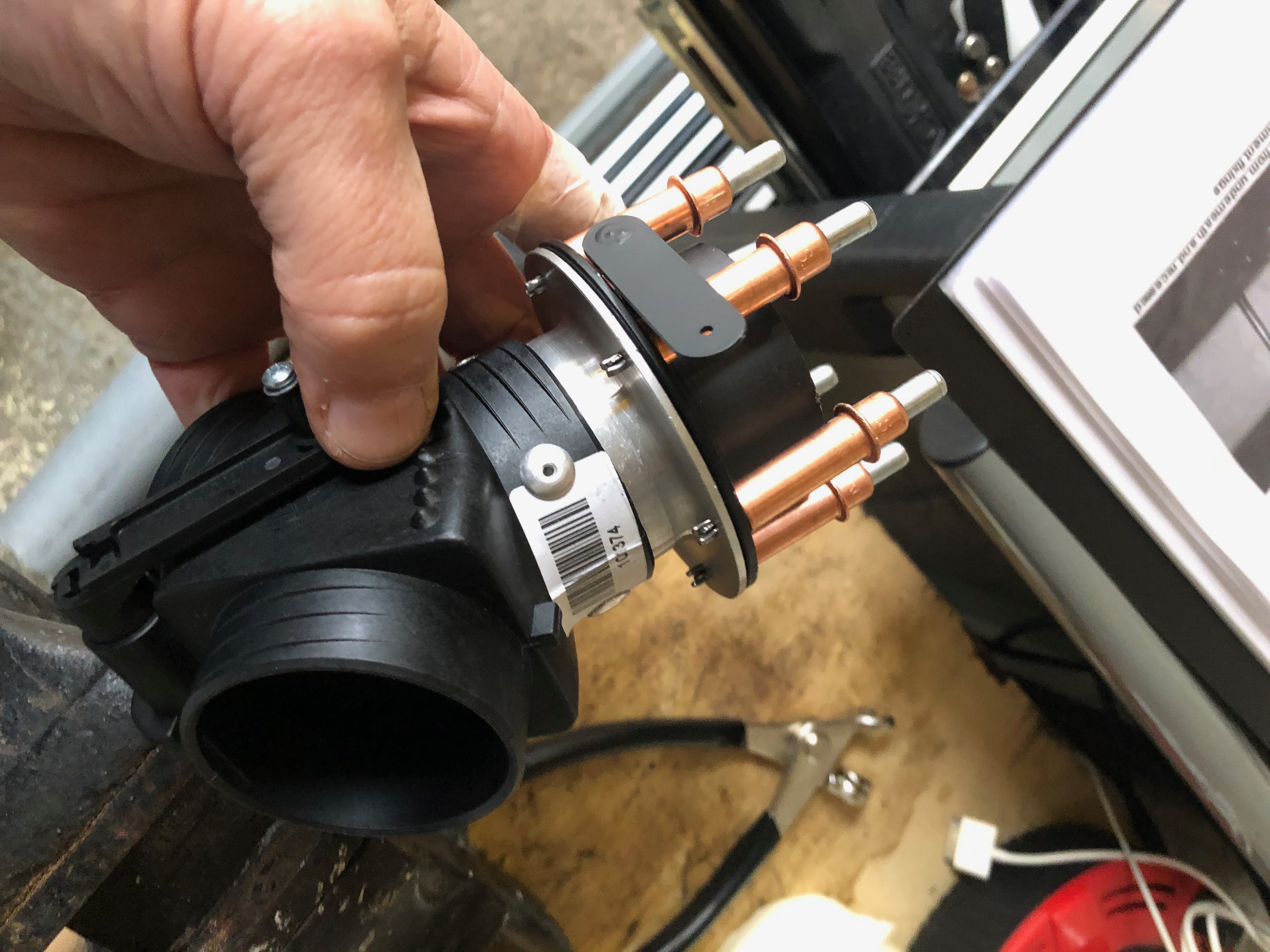
As the Bristell uses its own engine mount two of the pump aluminimum pipes need to be repositioned and the other two need to be replaced with modified pipes that come with the kit.
So the pump needs to be removed.
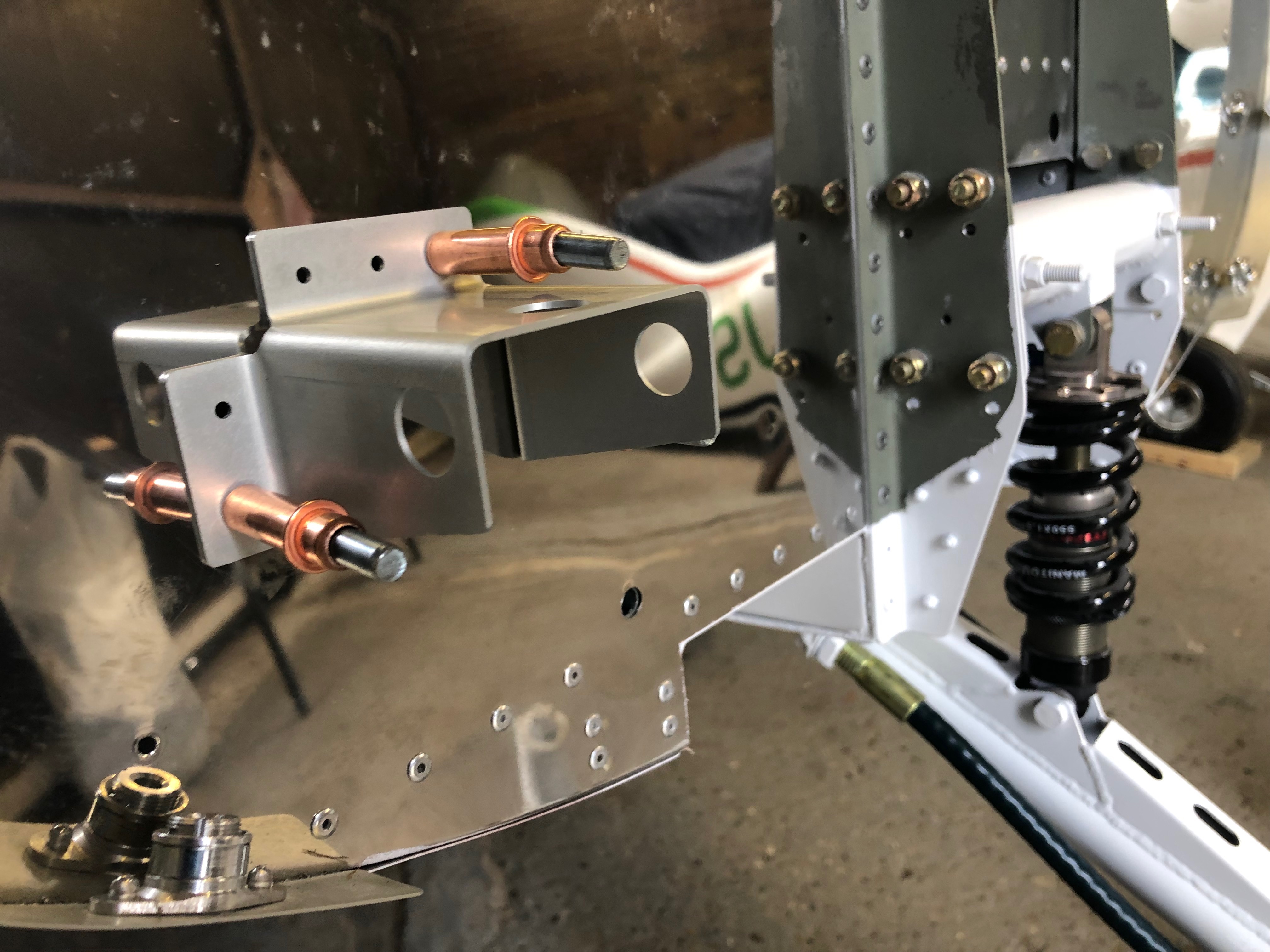
The engine mount needs to be fitted as it’s the only way that you can position the new water pump pipes. The mount is quite tight to fit and you need to make sure that you don’t catch any cables. The top right bolt needs to be removed as that becomes one of the engine mounting bolts that are fitted later.
As stated above, it’s a very tight fit so care must be taken to ensure that cables don’t get damaged. They will need to be protected before the engine goes into service.
The engine mount fitted. The water pump pipes need to be removed but I decided to think it through a bit more before carrying out the work tomorrow.
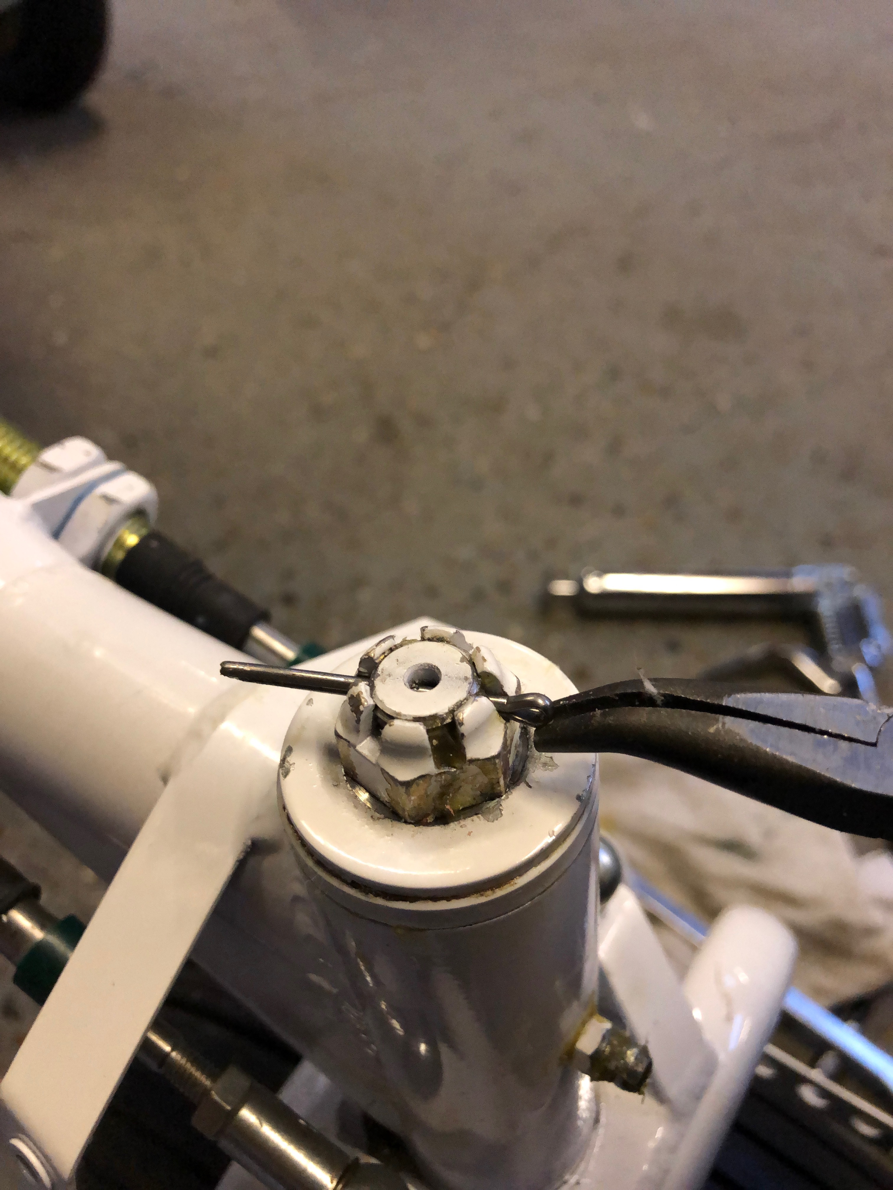
Now I have my grease gun I can fill the steering bearing with universal grease.
and then refit the castellated nut and fit a new split pin.
The other bearing that needs to be filled with grease is the nosebag pivot. It’s tricky to get to and once filled it’s tricky to remove the fitting from the grease nipple.
For peace of mind I’ve lowered the engine onto a beer crate and surrounded it with the packing that came with the engine so I can leave it overnight.
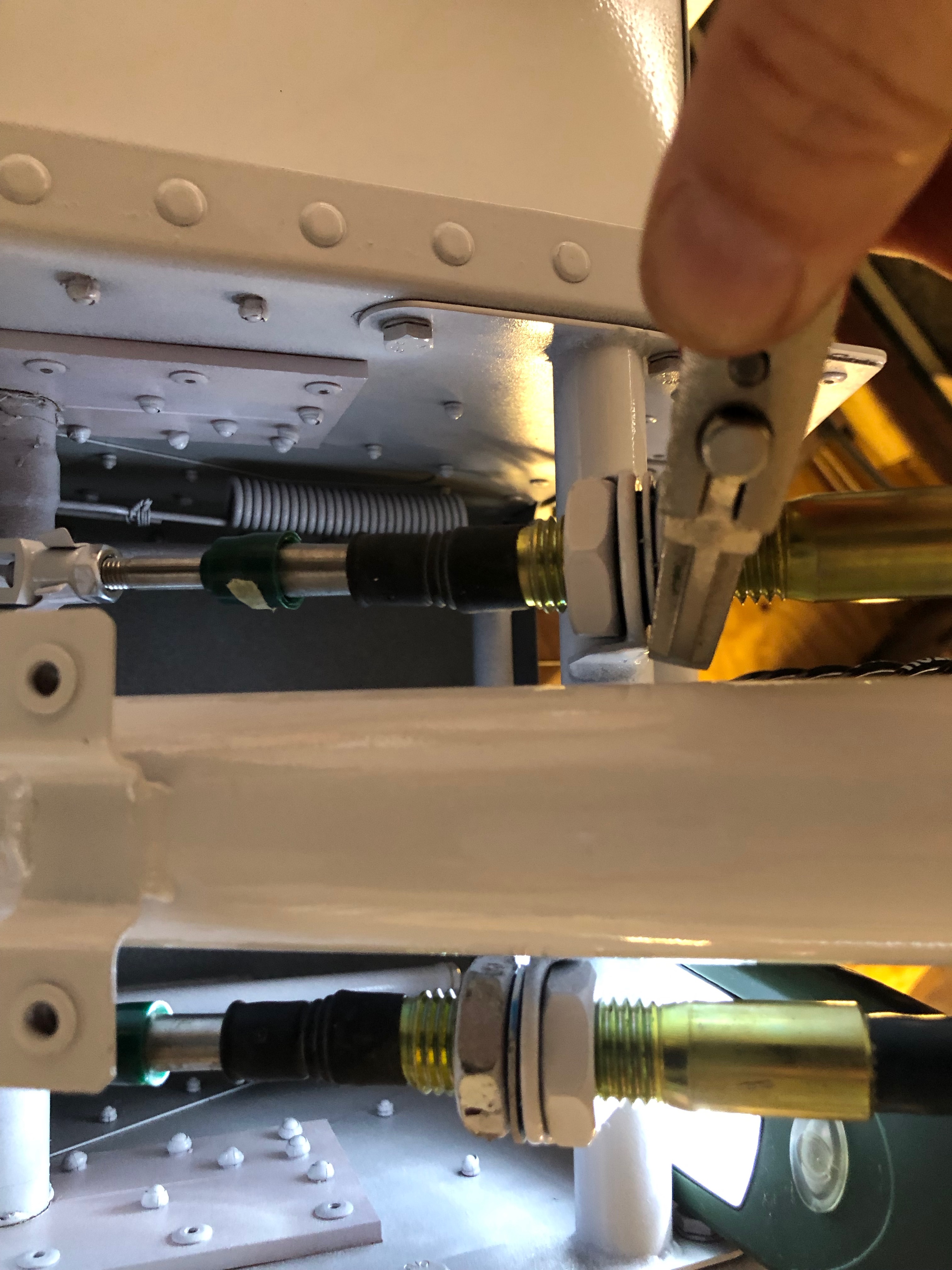
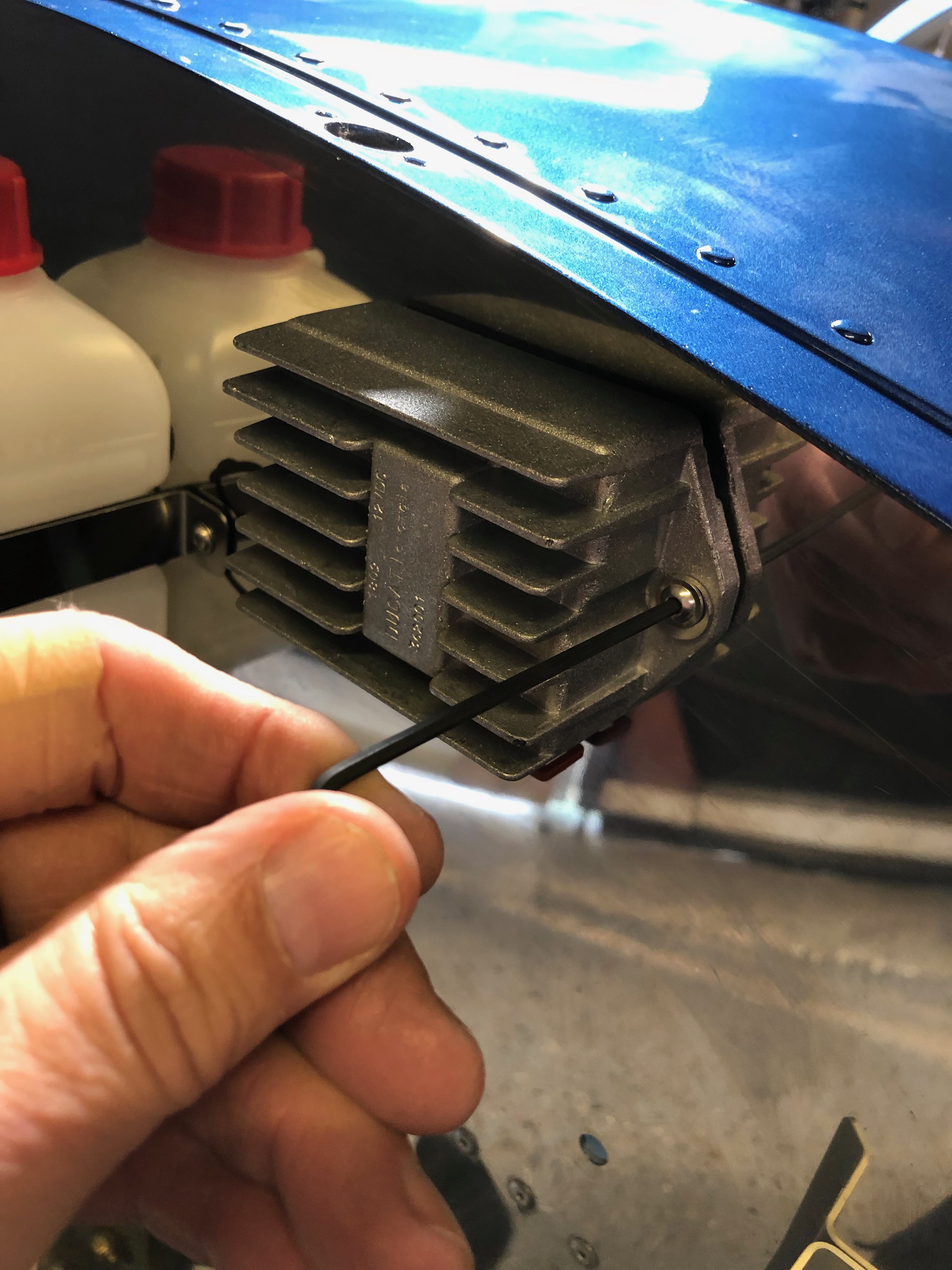
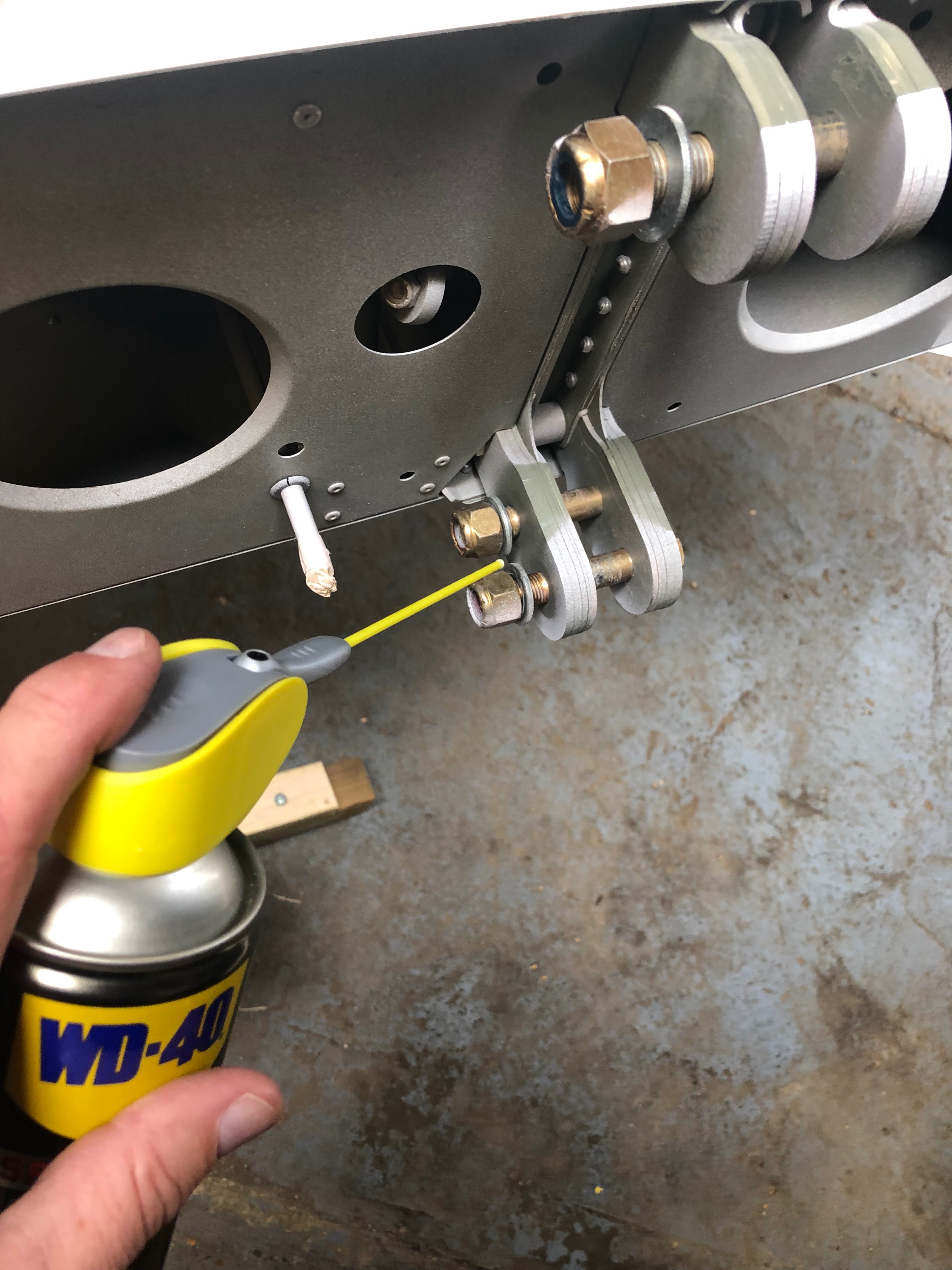
Although the Teleflex cables are already installed the nuts need to have Loctite 243 applied and retightened to ensure they don’t loosen during service.
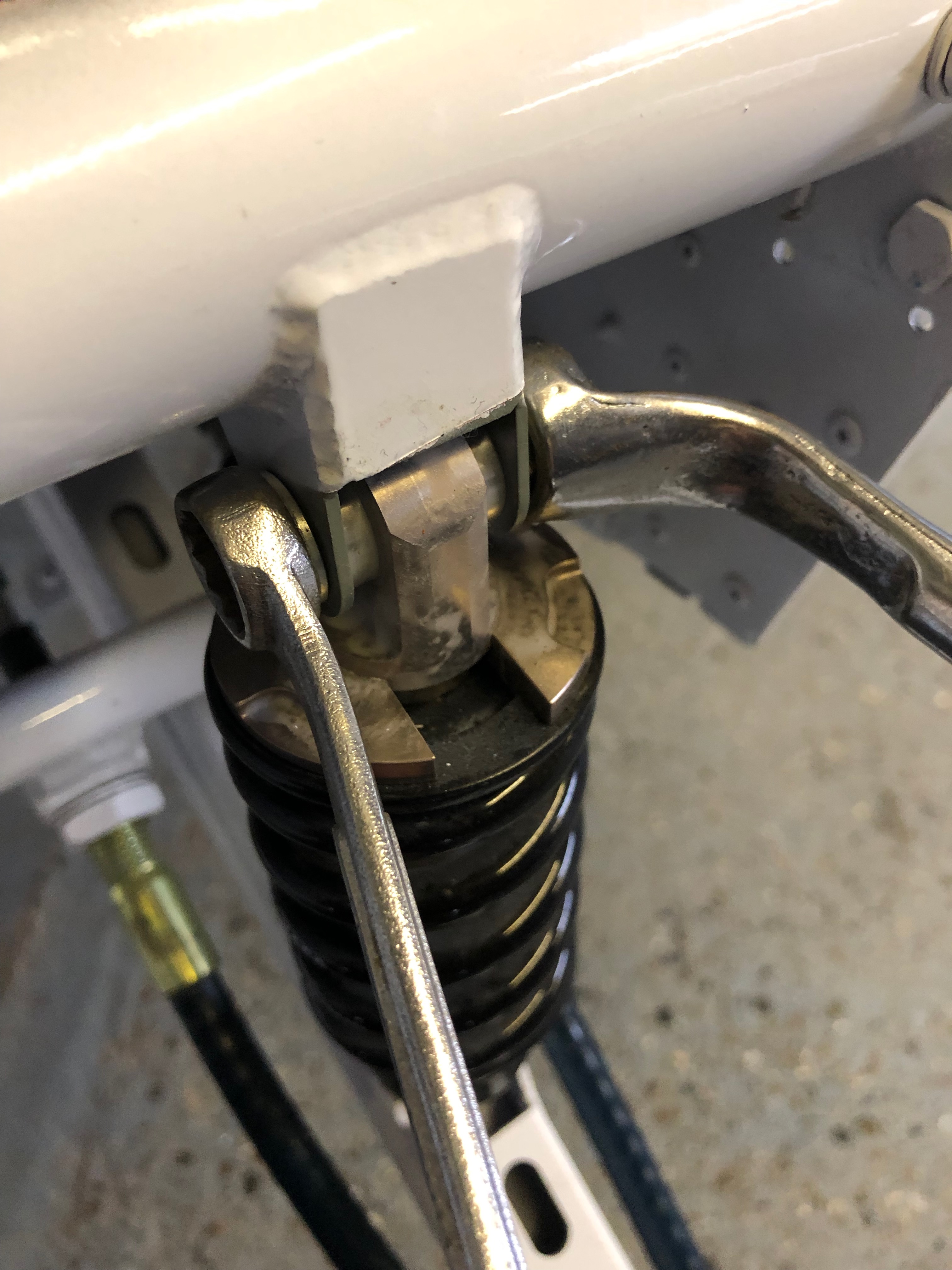
Not forgetting those underneath…
All the nuts and bolts also need to be checked.
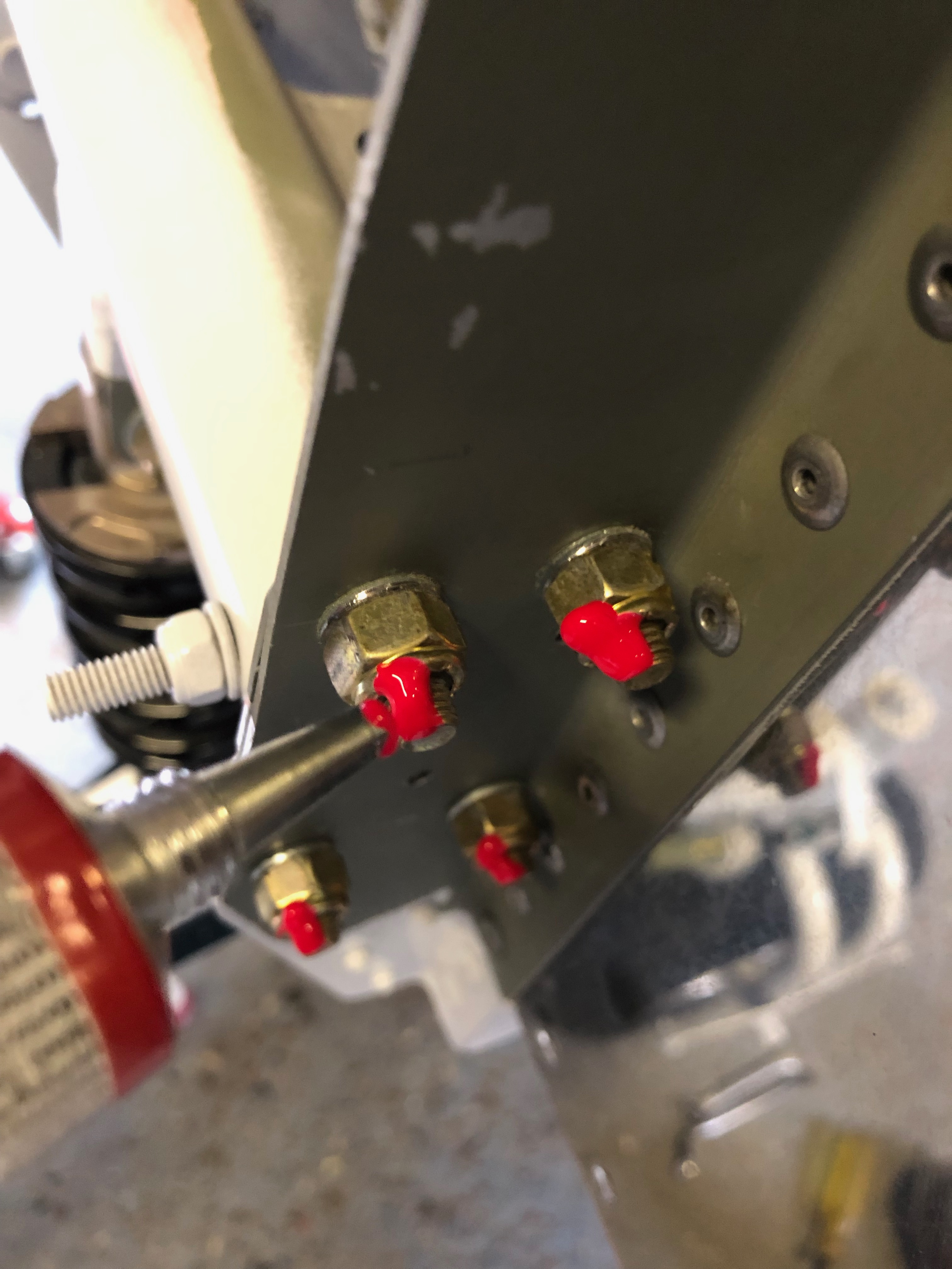
Once checked then Torque Seal is applied so an easy visual check can be made to ensure that they haven’t loosened.
I wasn’t happy with the screws used for mounting the control unit so I removed the Rivnuts and used M6 stainless steel nuts and bolts instead.
A view of the Firewall with the Torque Seal clearly visible.
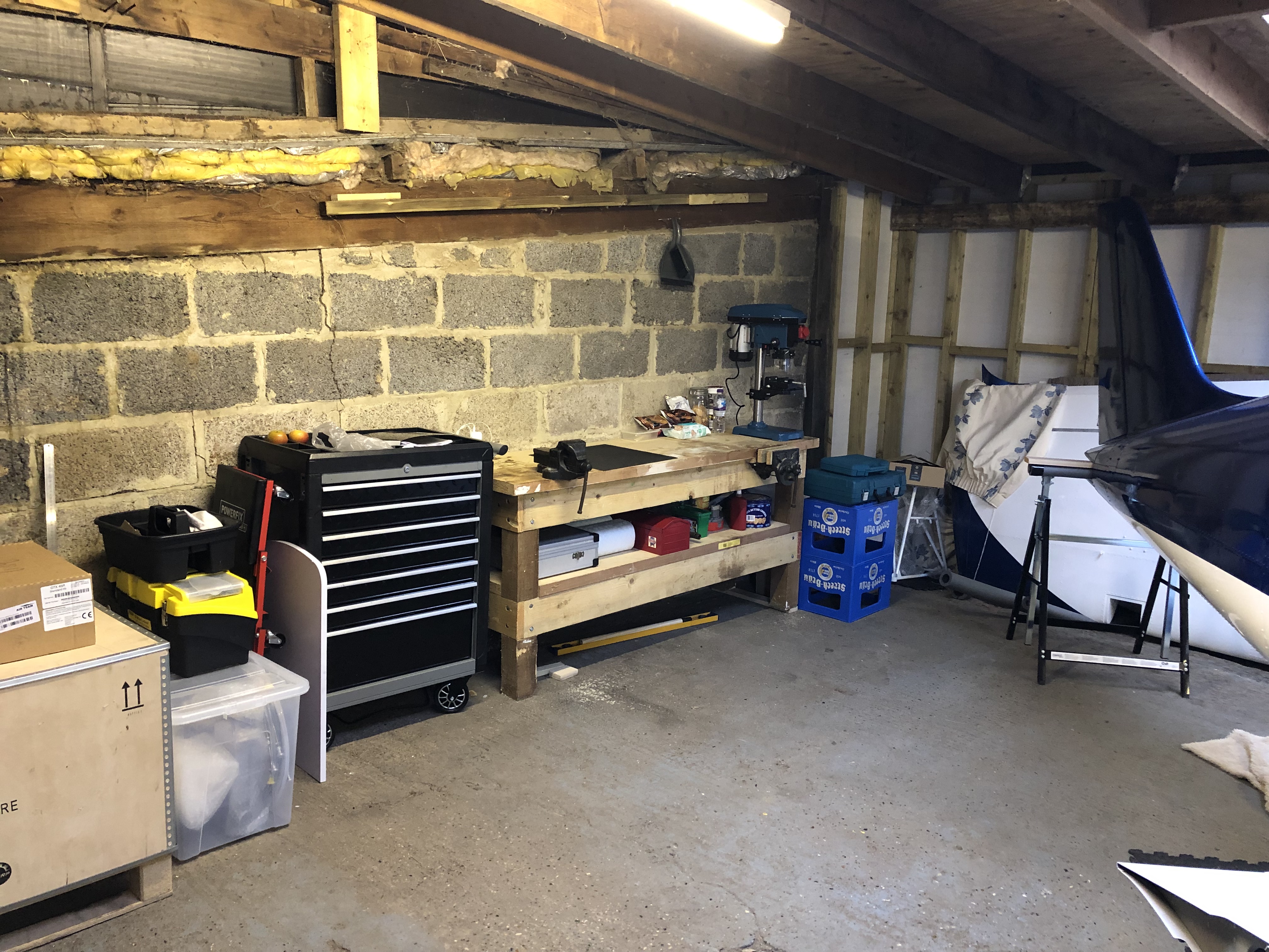
A tidy of the workshop was required to give me a bit more space on the workbench and clear area to work in.
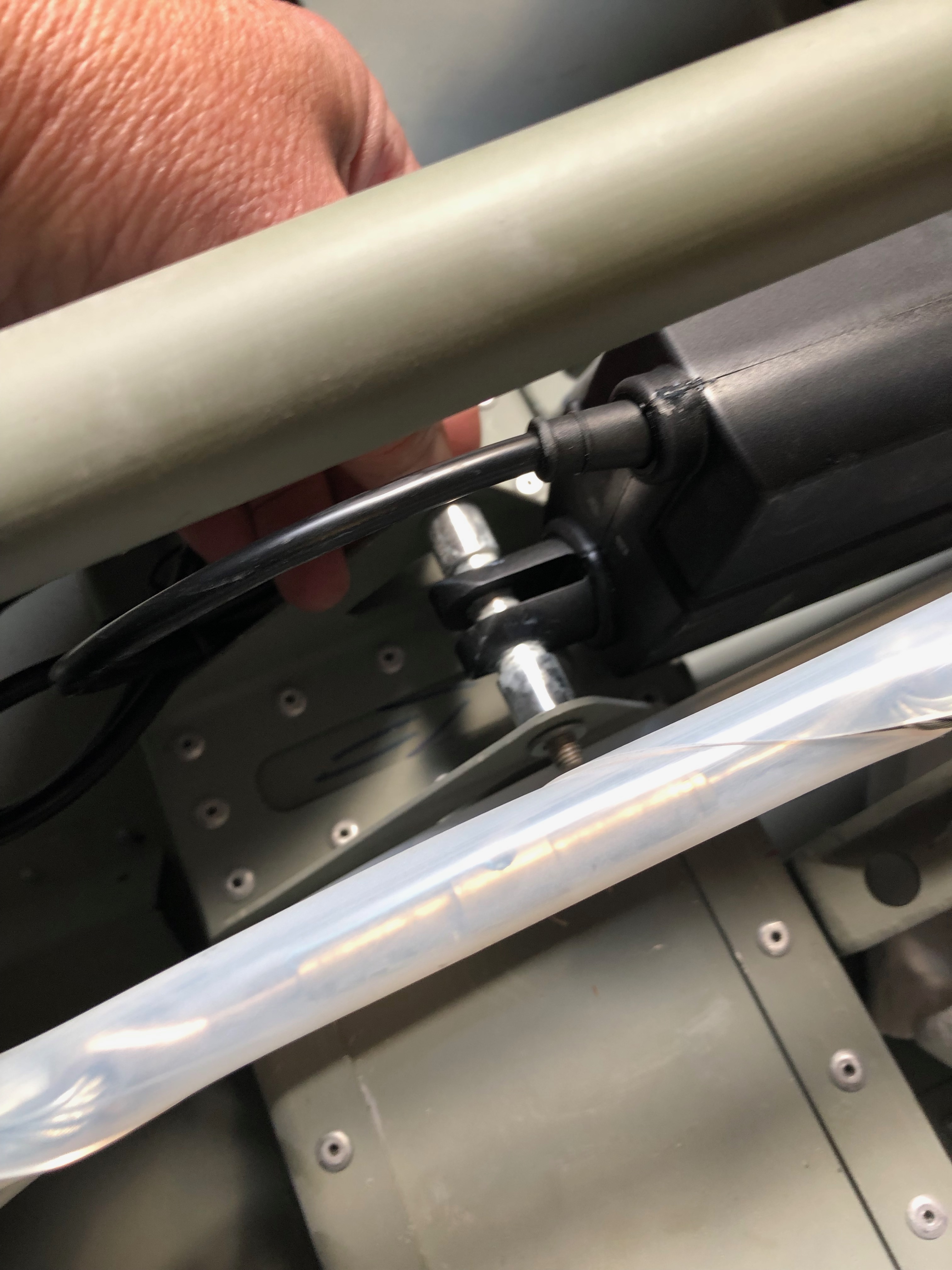
Time to install the flap motor. The bushes need to be sprayed with Lithium grease and then installed.
Fairly easy install but just a bit fiddly to install. You must connect the flap motor arm to the flap actuating arm first as you can’t get the bolt in after.
Motor installed.
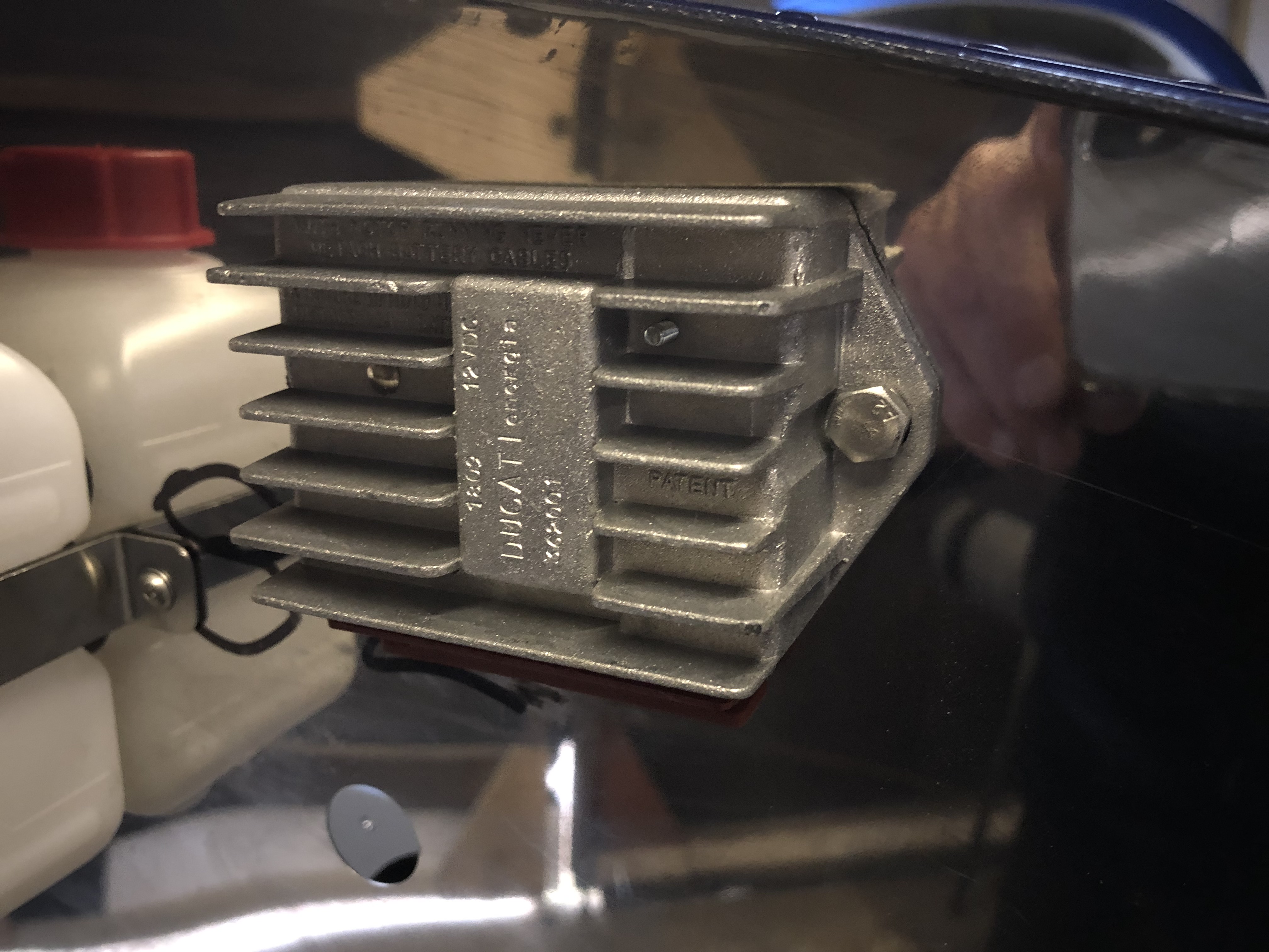
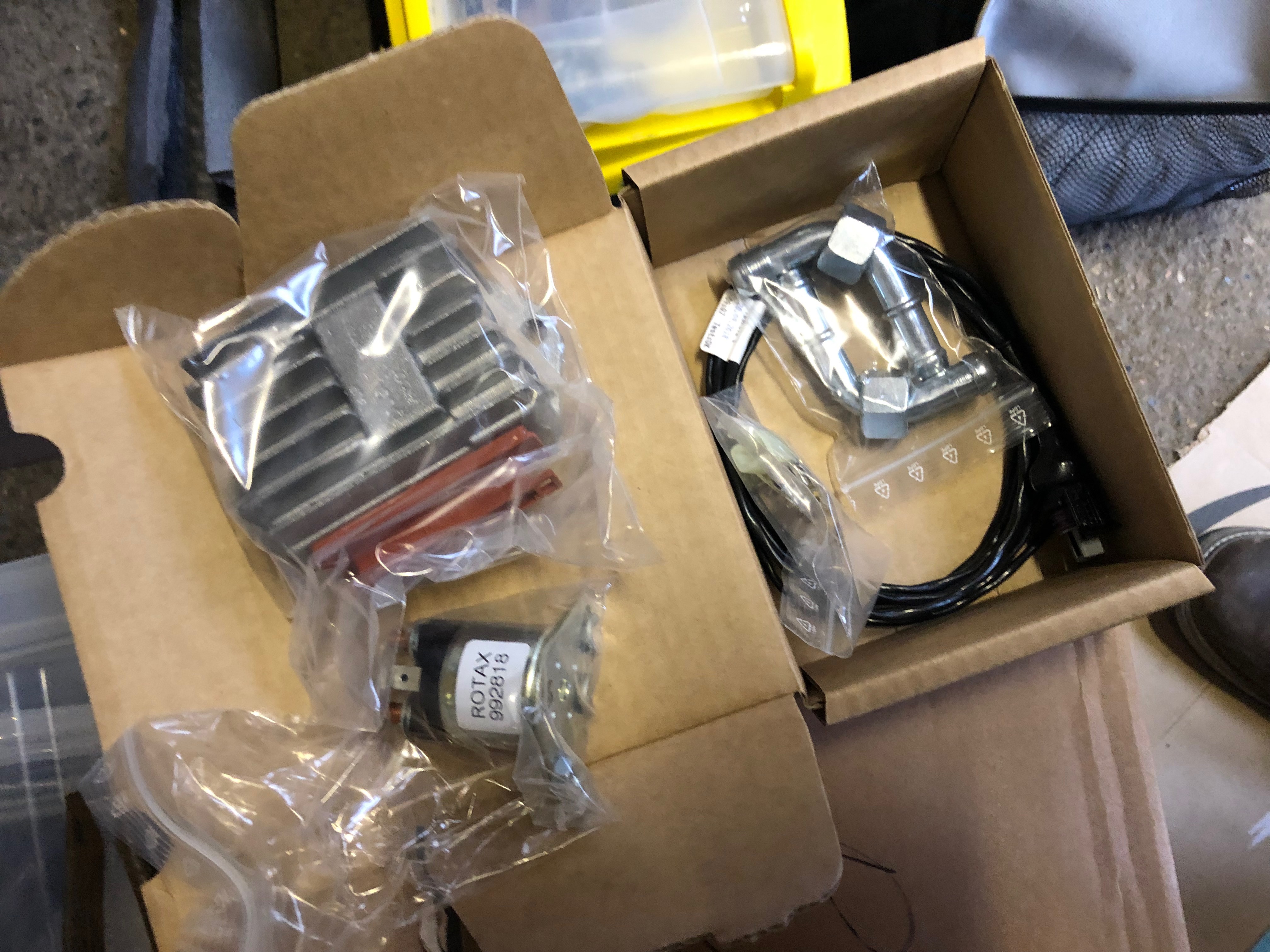
Next to be installed is the starter solenoid. A couple of M4 Rivnuts are installed with hex top screws to fix.
Now the Rotax control unit is installed using Rivnuts and screws.
The Firewall at the end of the day.
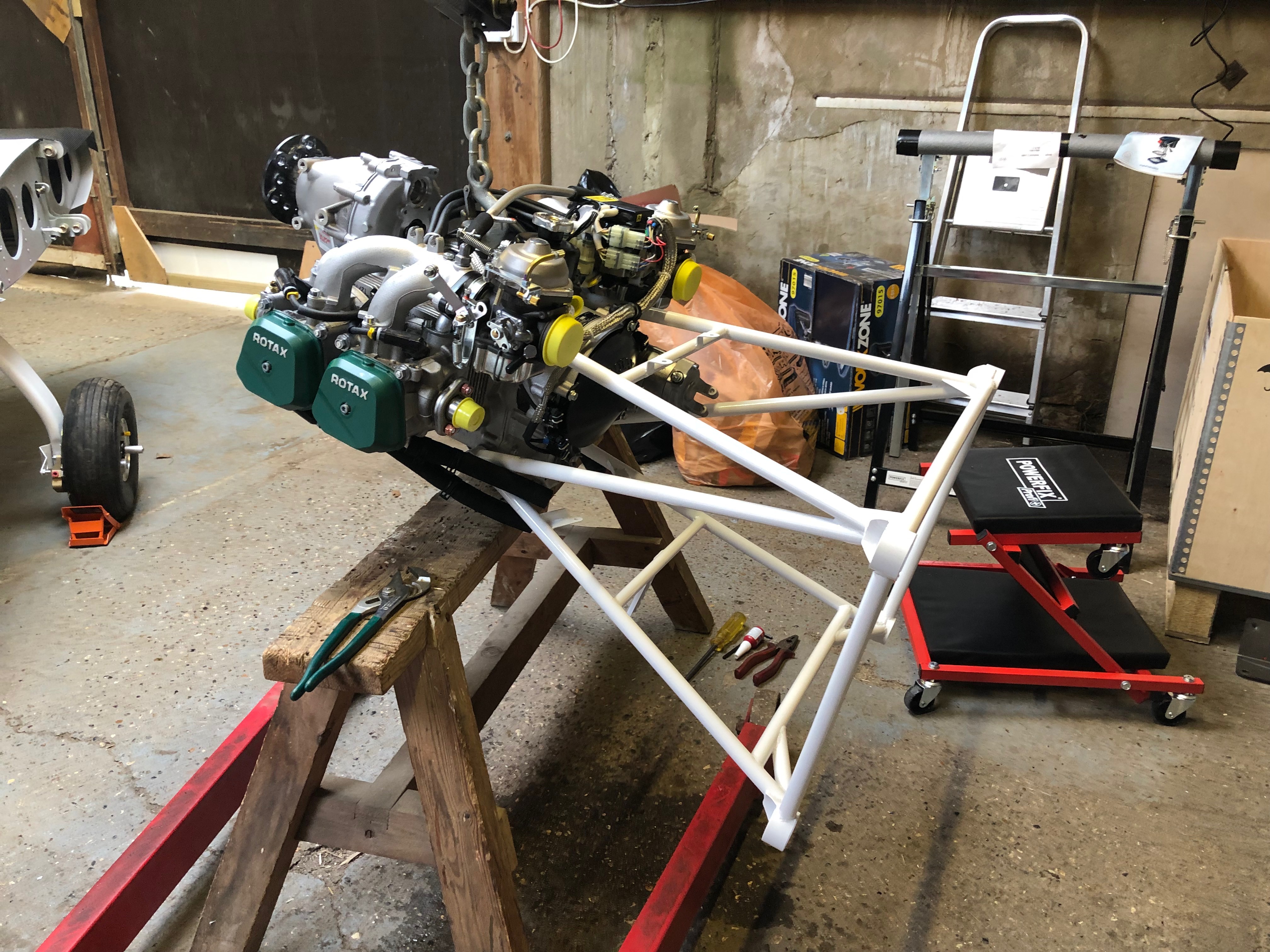
The engine needs to be lifted out of the crate and suspended whist the water pump is modified and engine mount is attached.
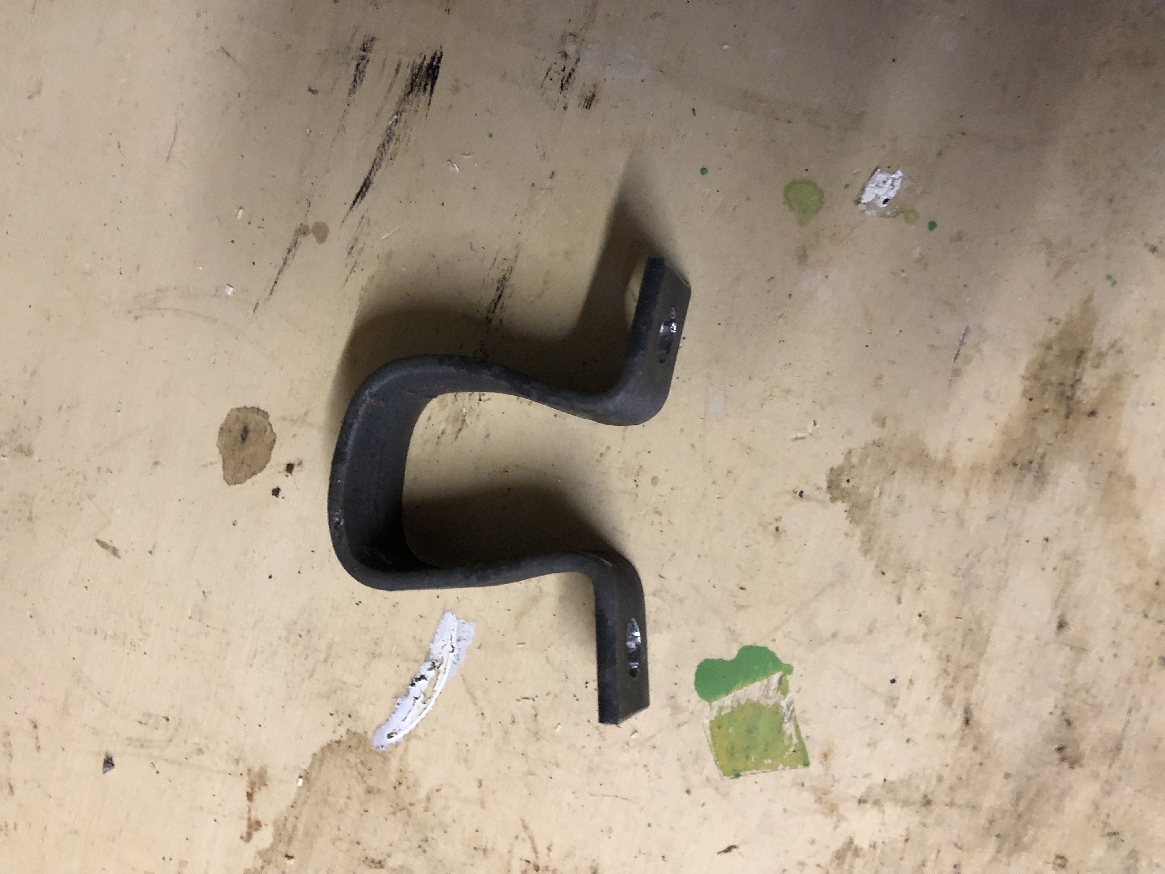
A bracket needed to be made from steel bar so it can be used for lifting.
Oil tank bracket. I’ve decided to use a different rivet gun which helps speed up the job
Gascolator bracket
Heater control cable bracket
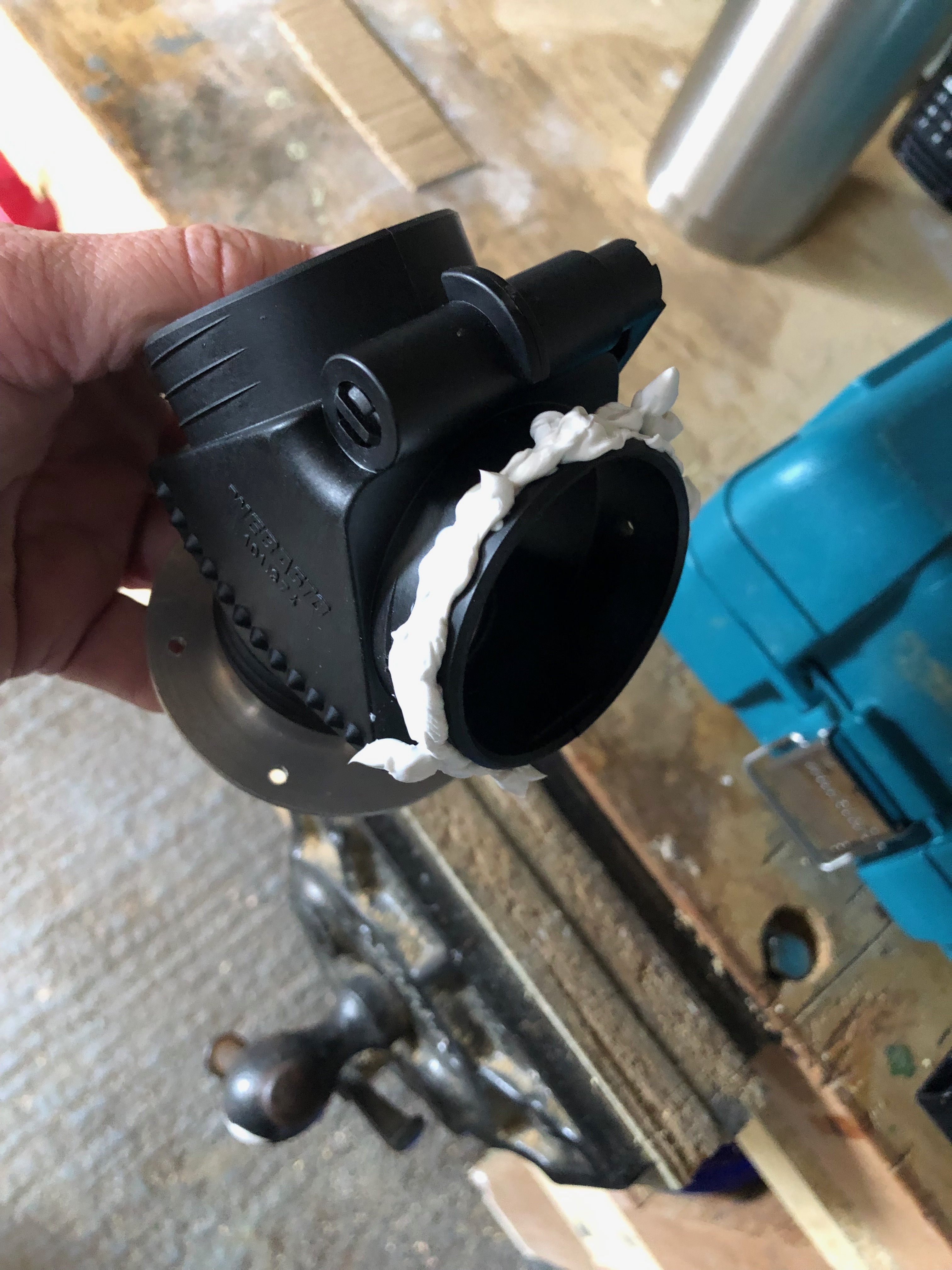
The fuel pump and firewall air ducts are next to be fitted once the canopy is removed
To ensure the wing root bolts don’t rust some lithium grease was sprayed on them
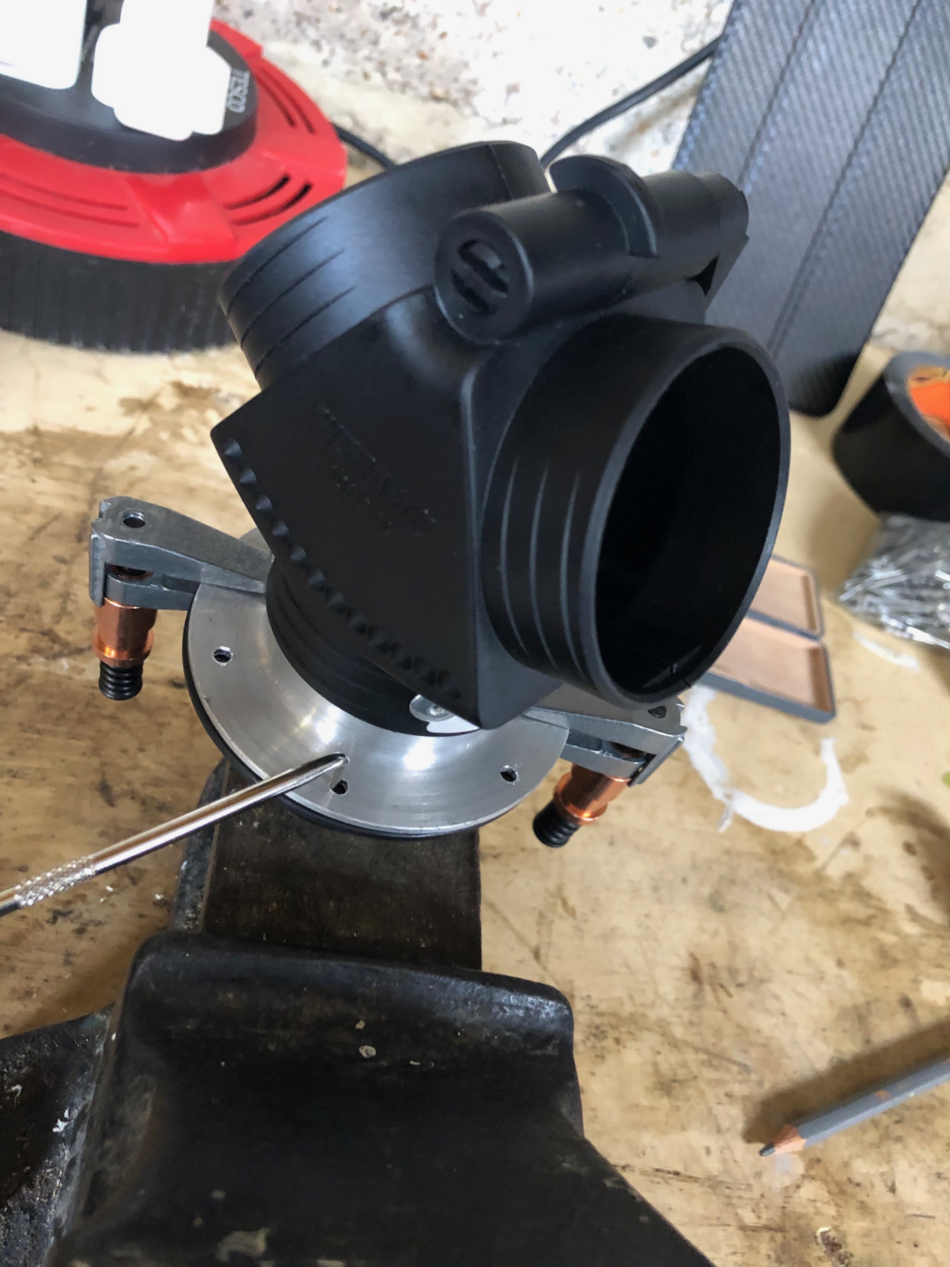
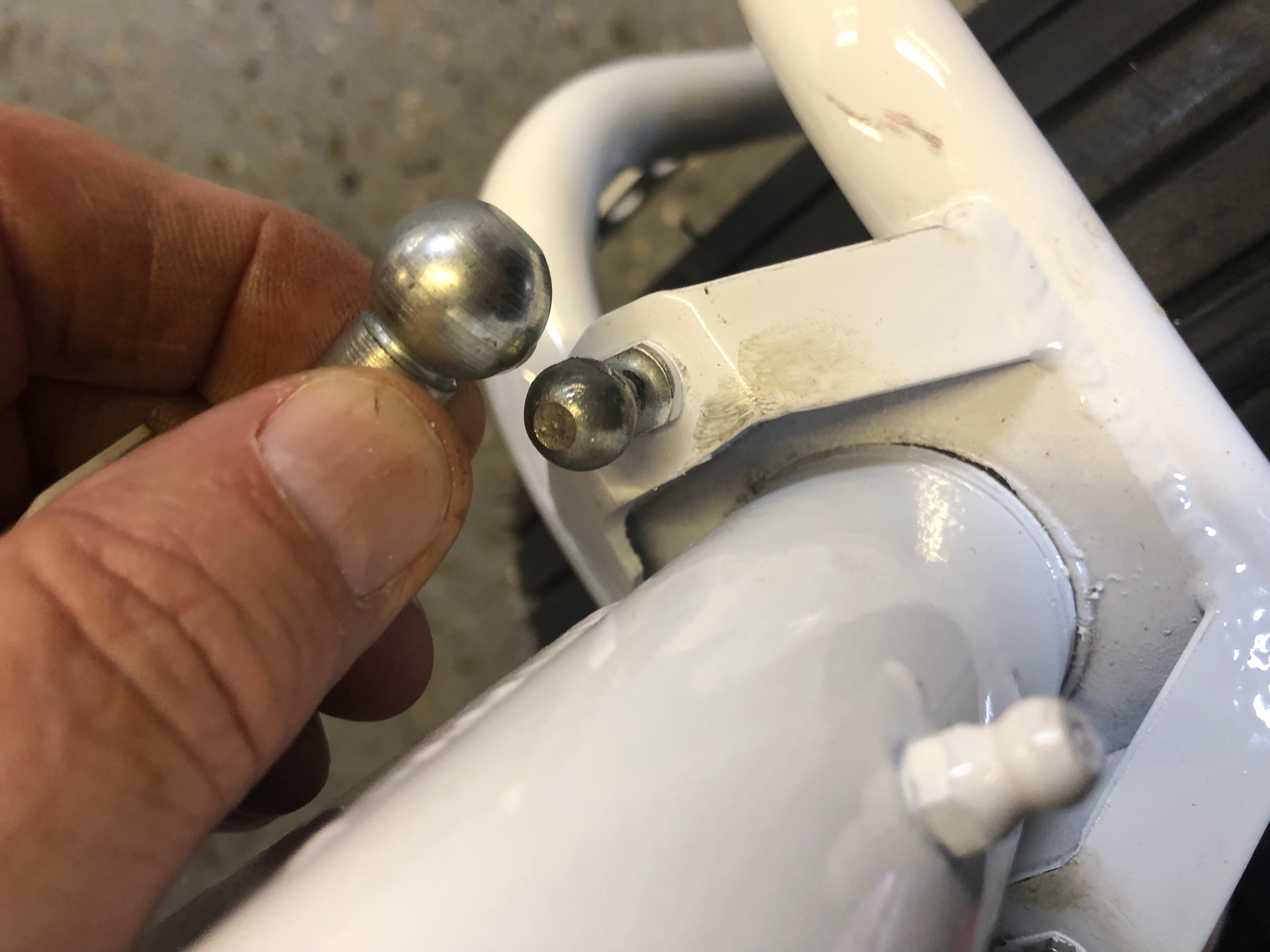
Steering cable ball connectors were removed, greased and refitted
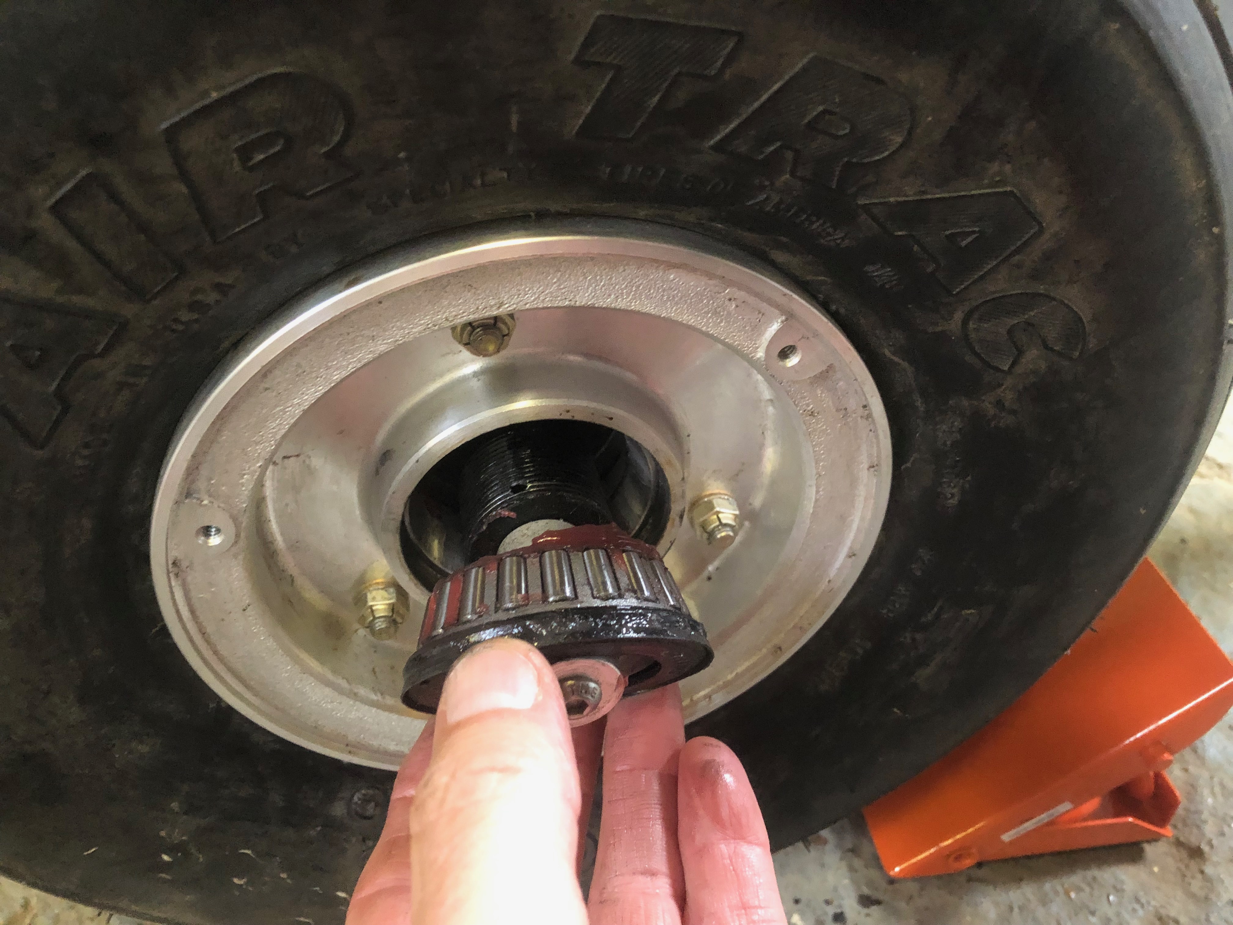
The kit comes with the wheels, hubs and brake callipers fitted to facilitate transport and movement but are not final fit so need to be removed, greased, checked and refitted ensuring all bolts are correctly torqued.
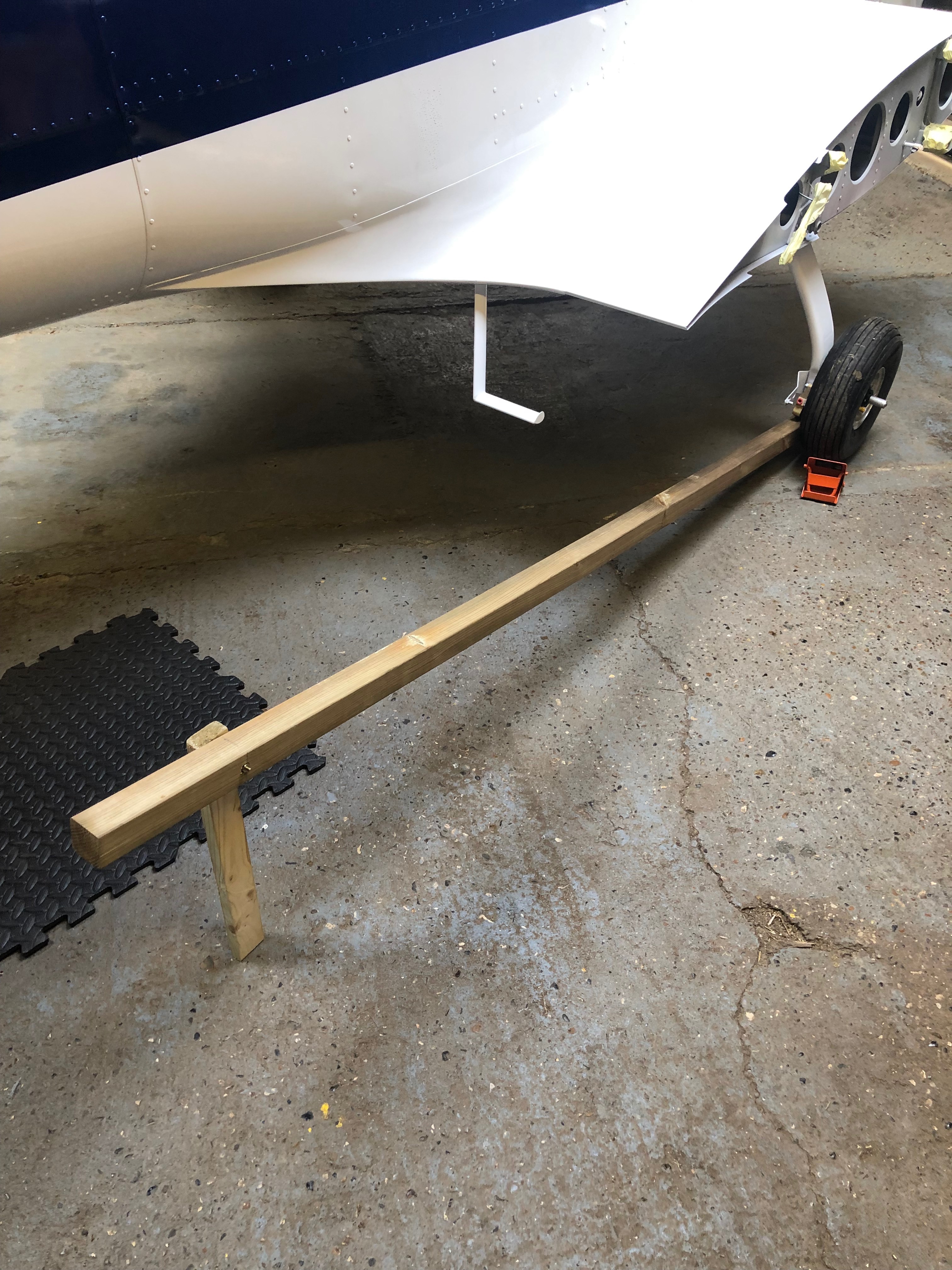
To jack the aircraft so the wheel bearing can be removed and greased a simple wooden jack is made.
To help lift the wheel off the ground a suitable ‘jack’ was made from a length of 2″ x 2″ wood.
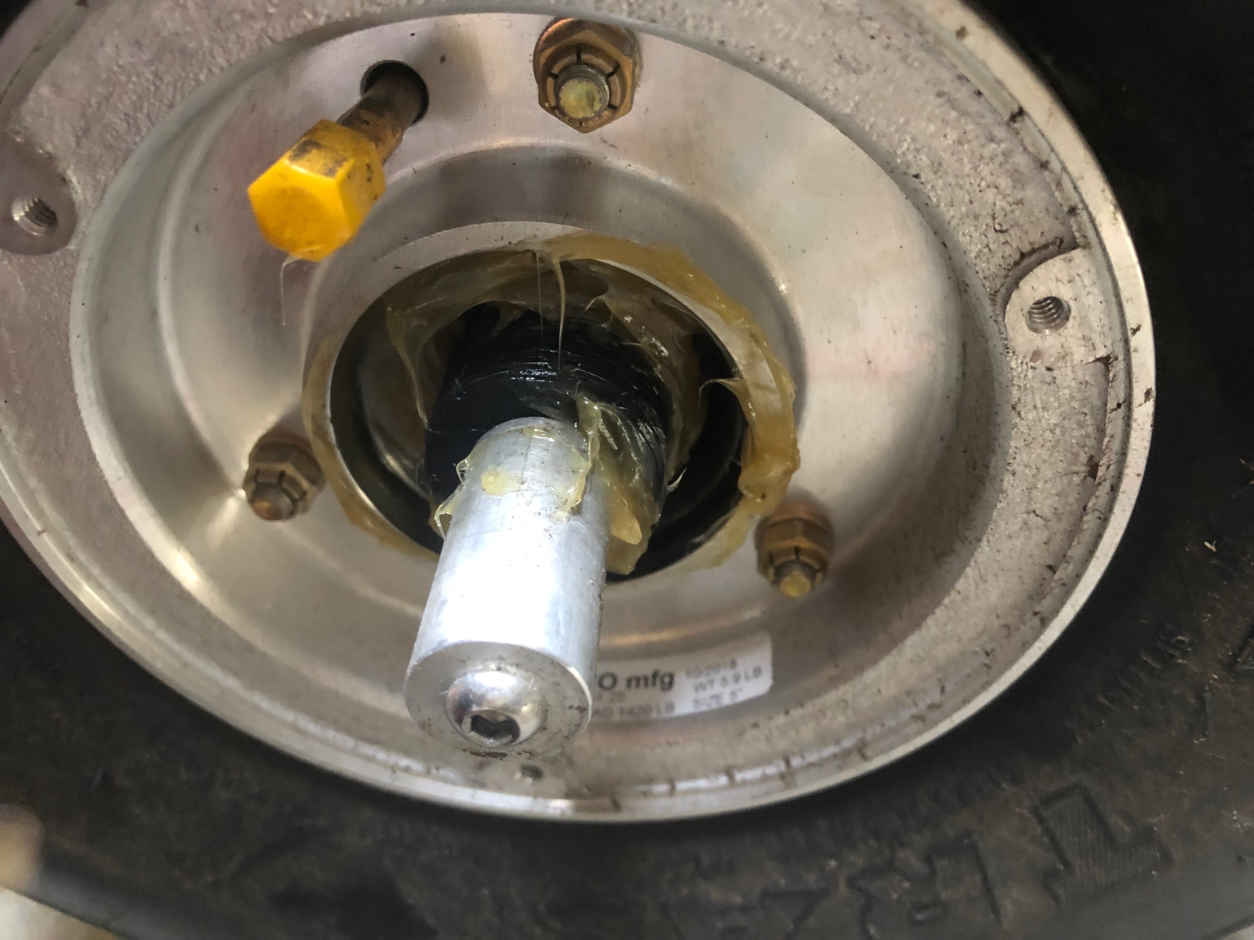
Once the wheel is clear of the ground the bearings are removed
Recess packed with grease.
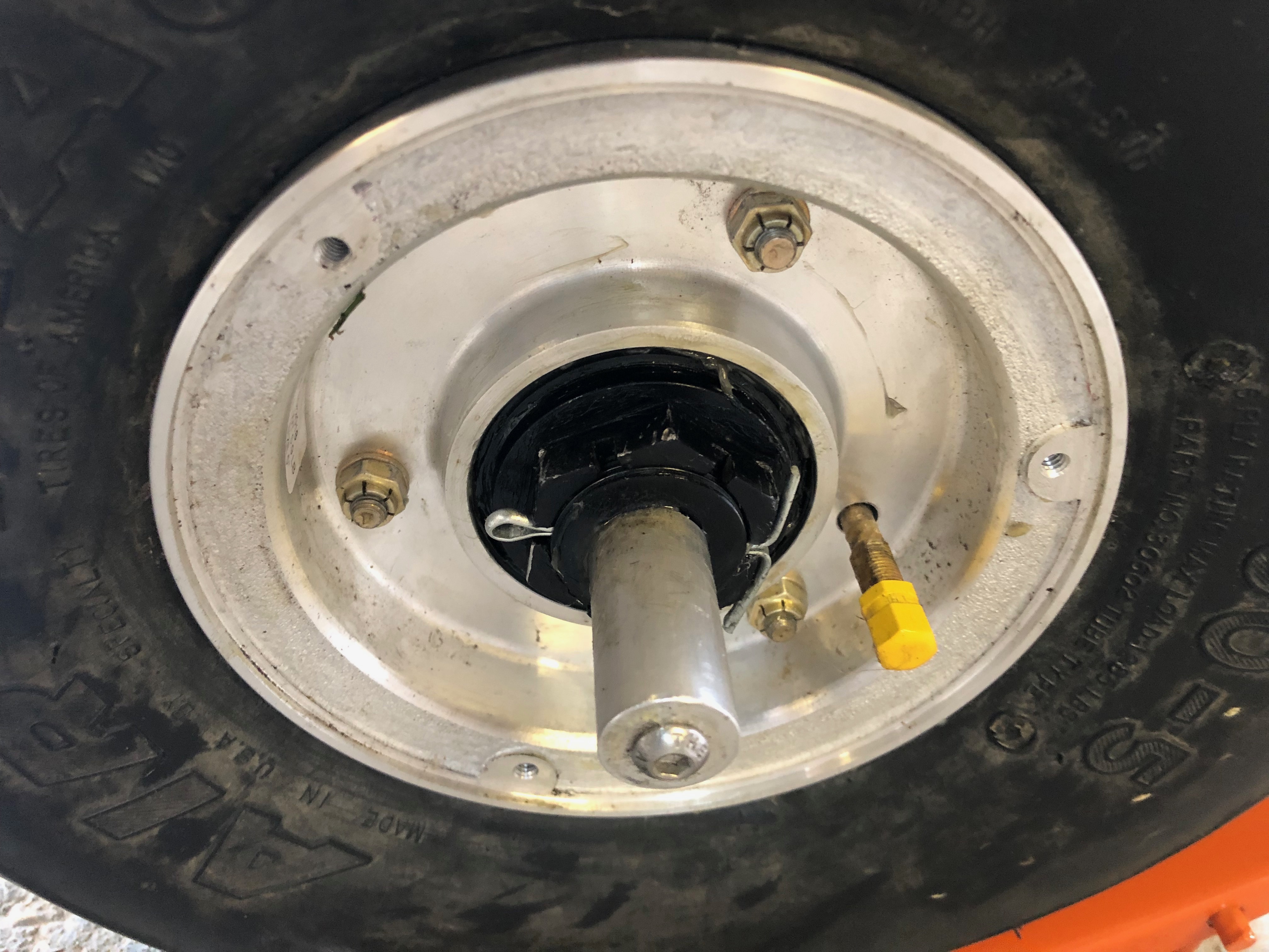
Wheel bearing is refitted, the wheel nut is refitted, tightened and a new split pin fitted.
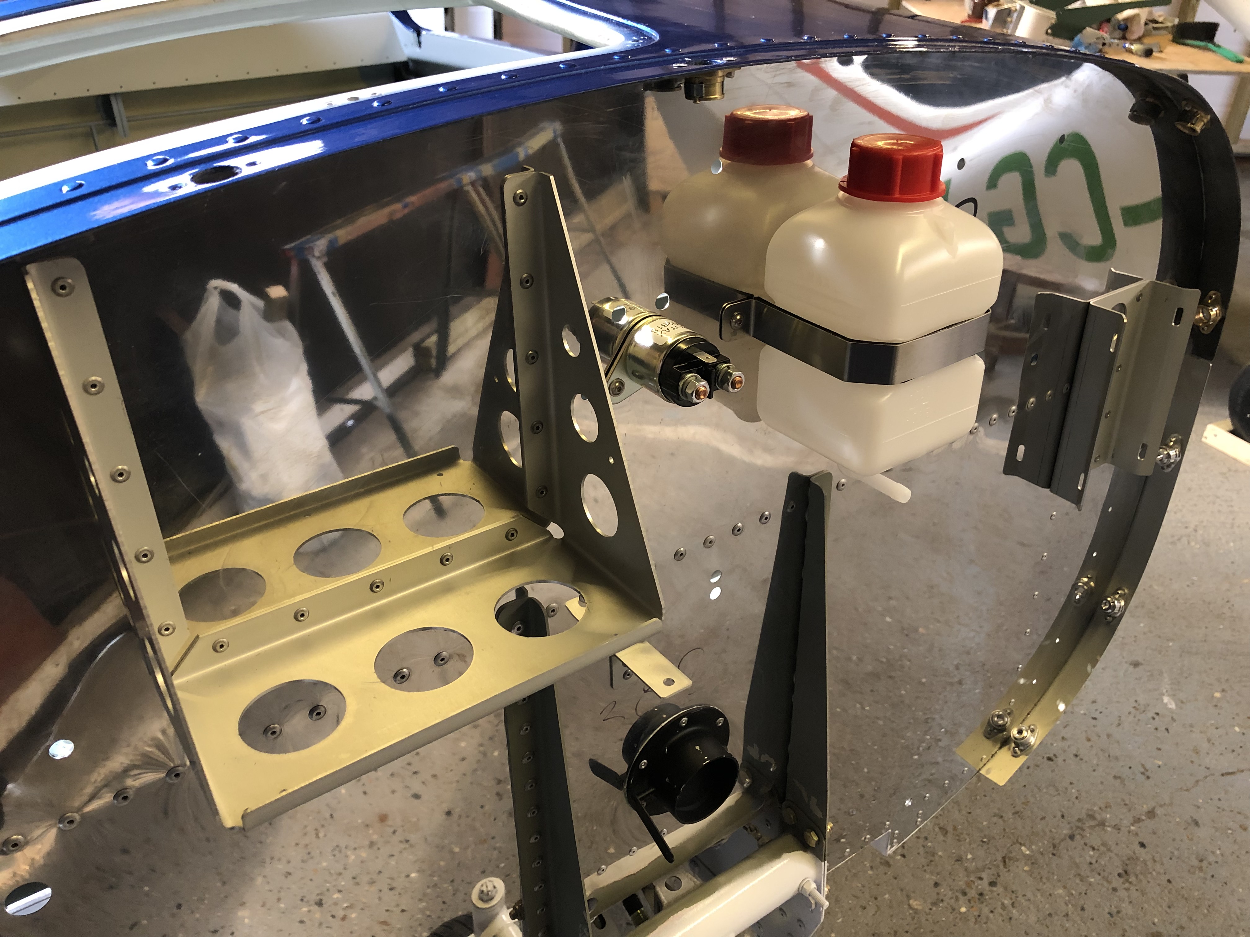
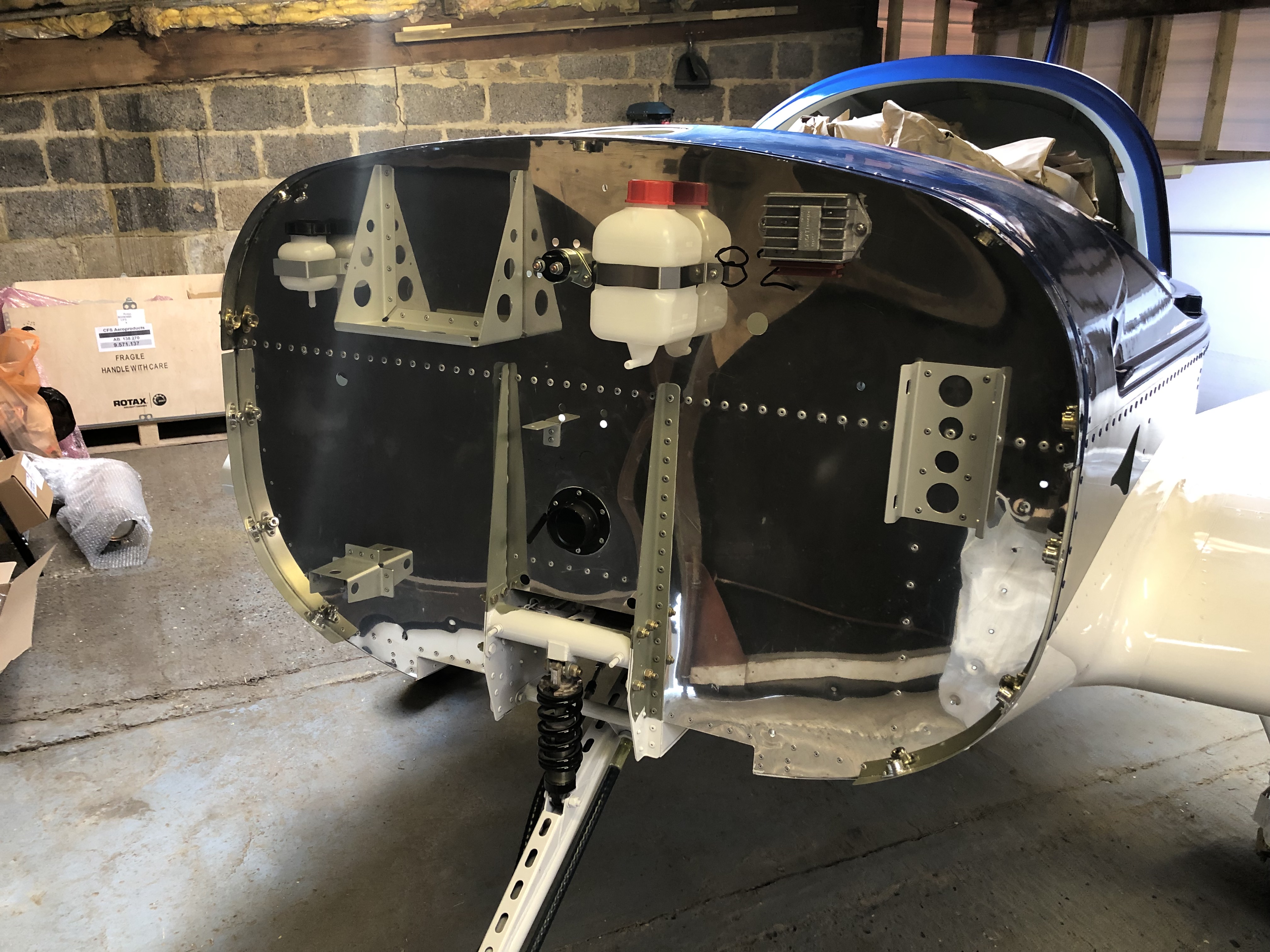
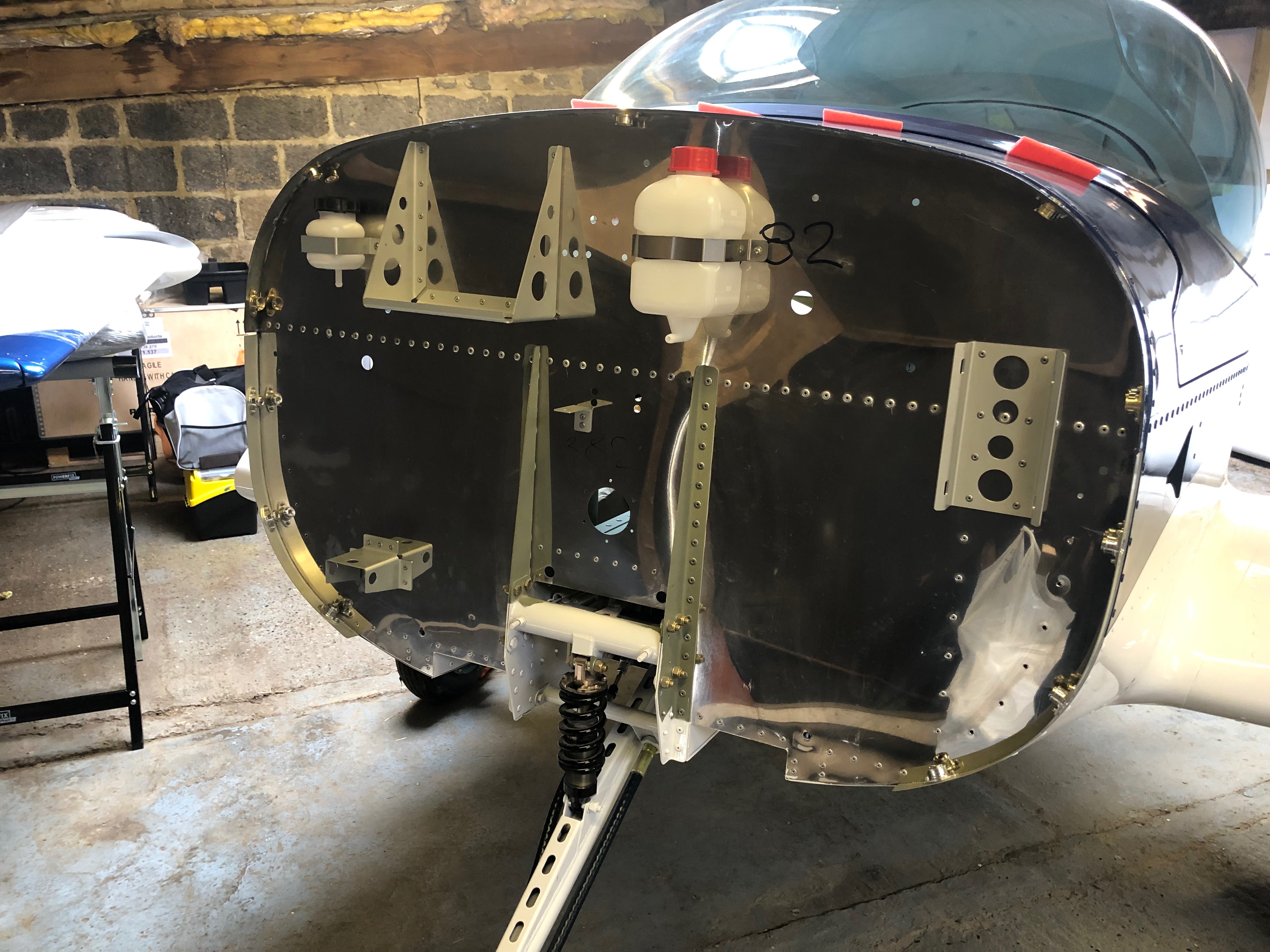
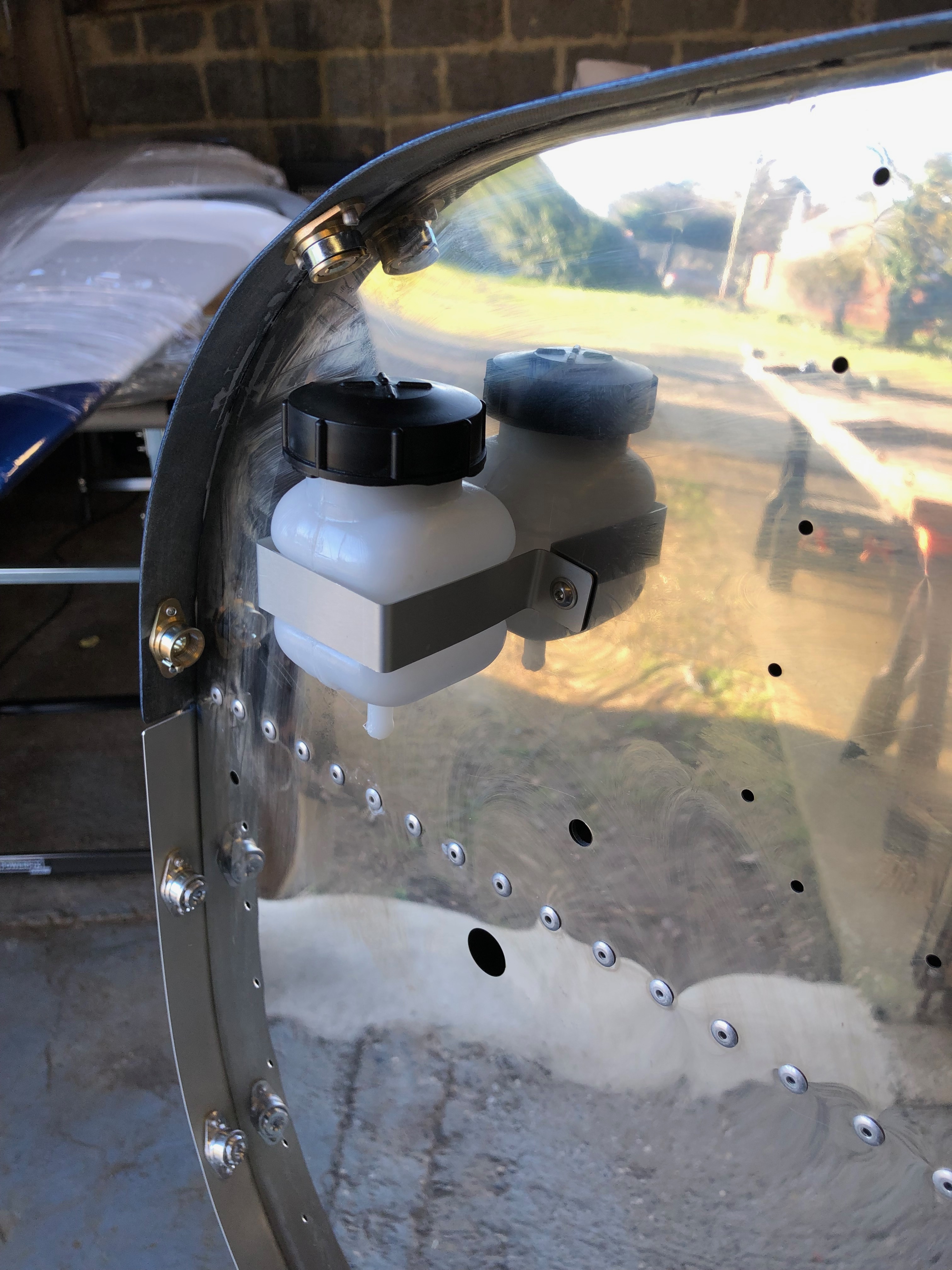
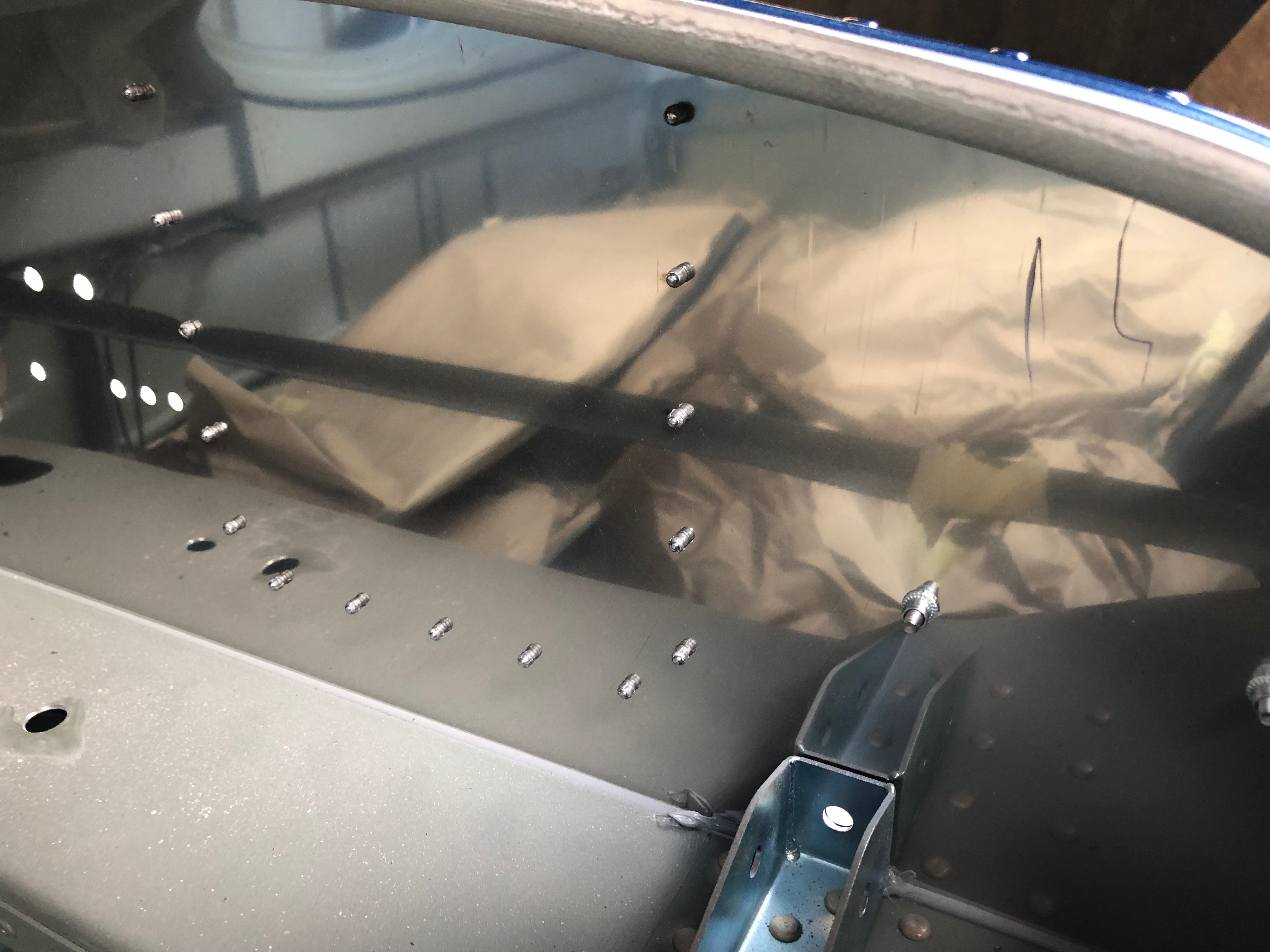
A number of brackets, bottles and components need to be installed before the engine is hung as it’s far easier to gain access to it. Some are just riveted onto the Firewall but other items need to be removed for servicing so Rivnuts are used with hex screws.
Setting an M4 Rivnut
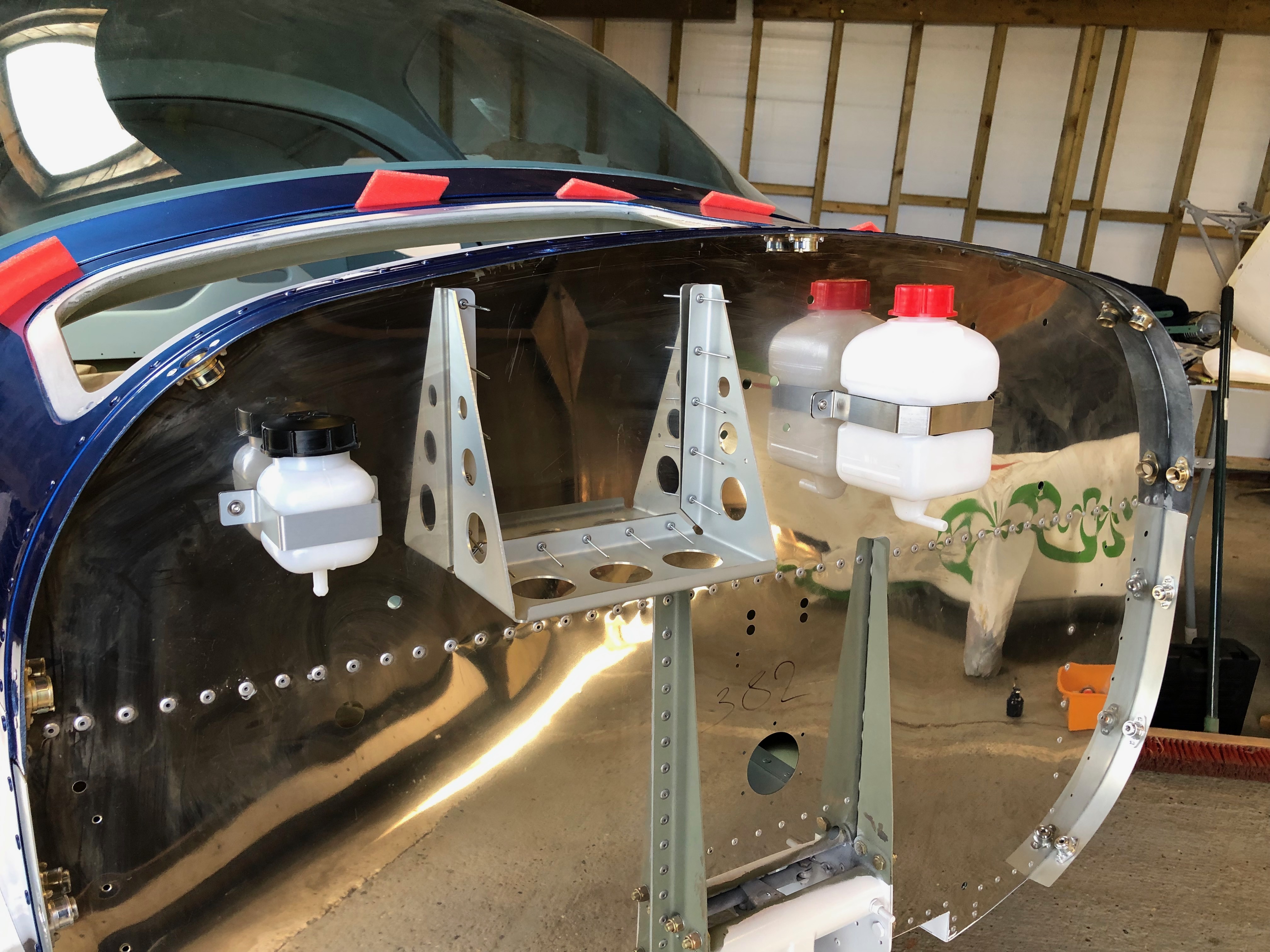
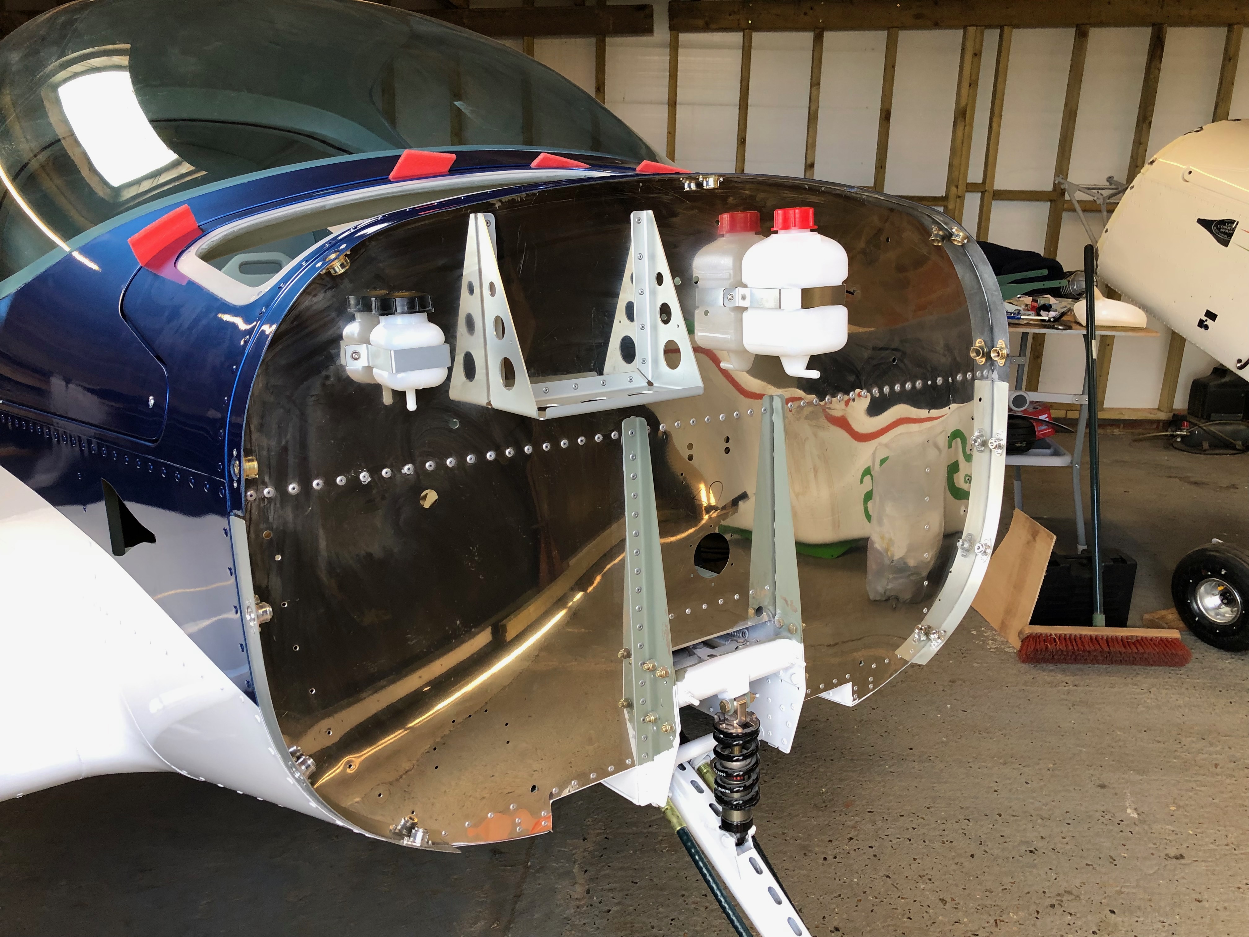
Brake Oil bottle installed
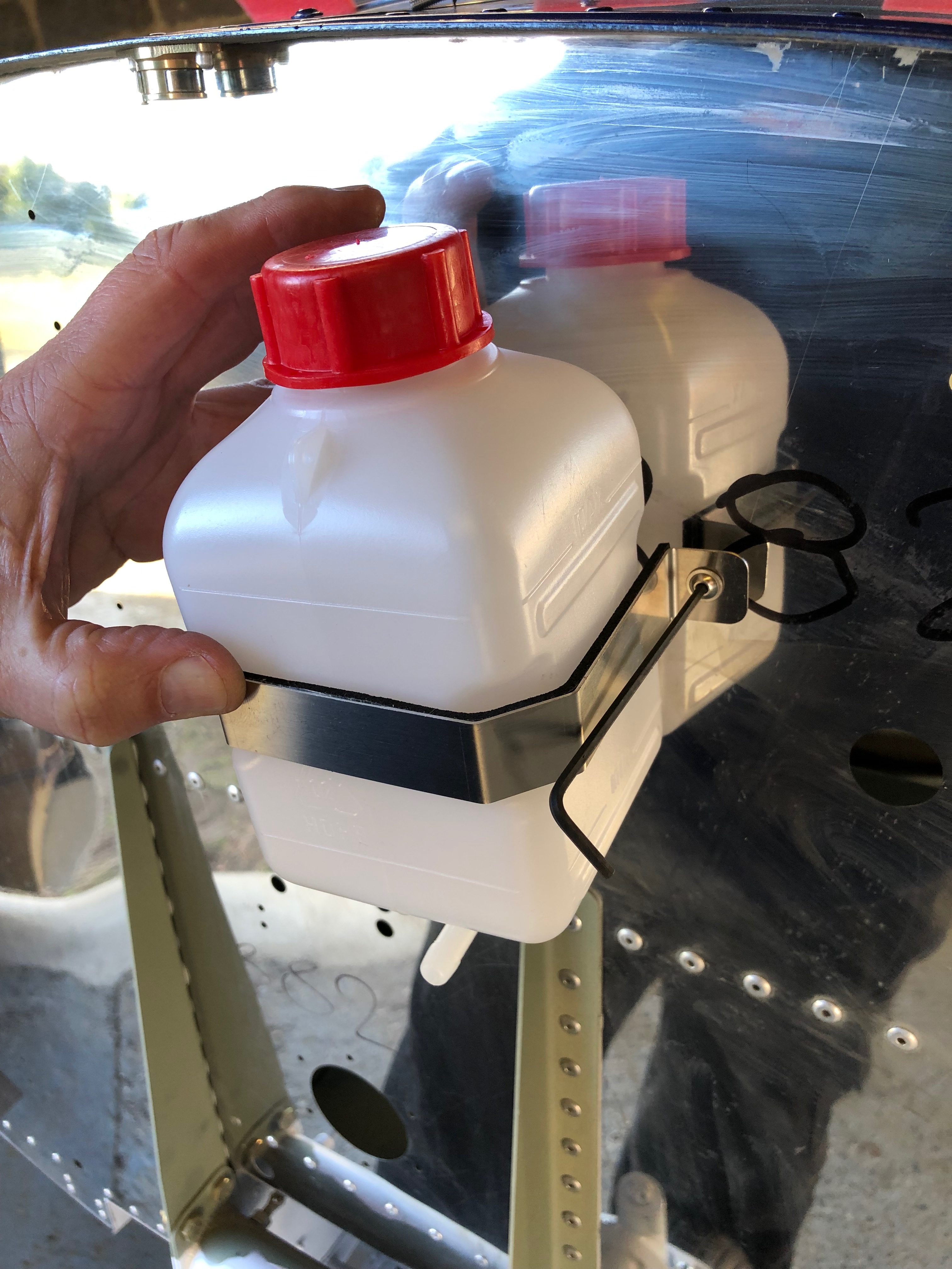
Repeating the procedure for the Rotax water expansion tank
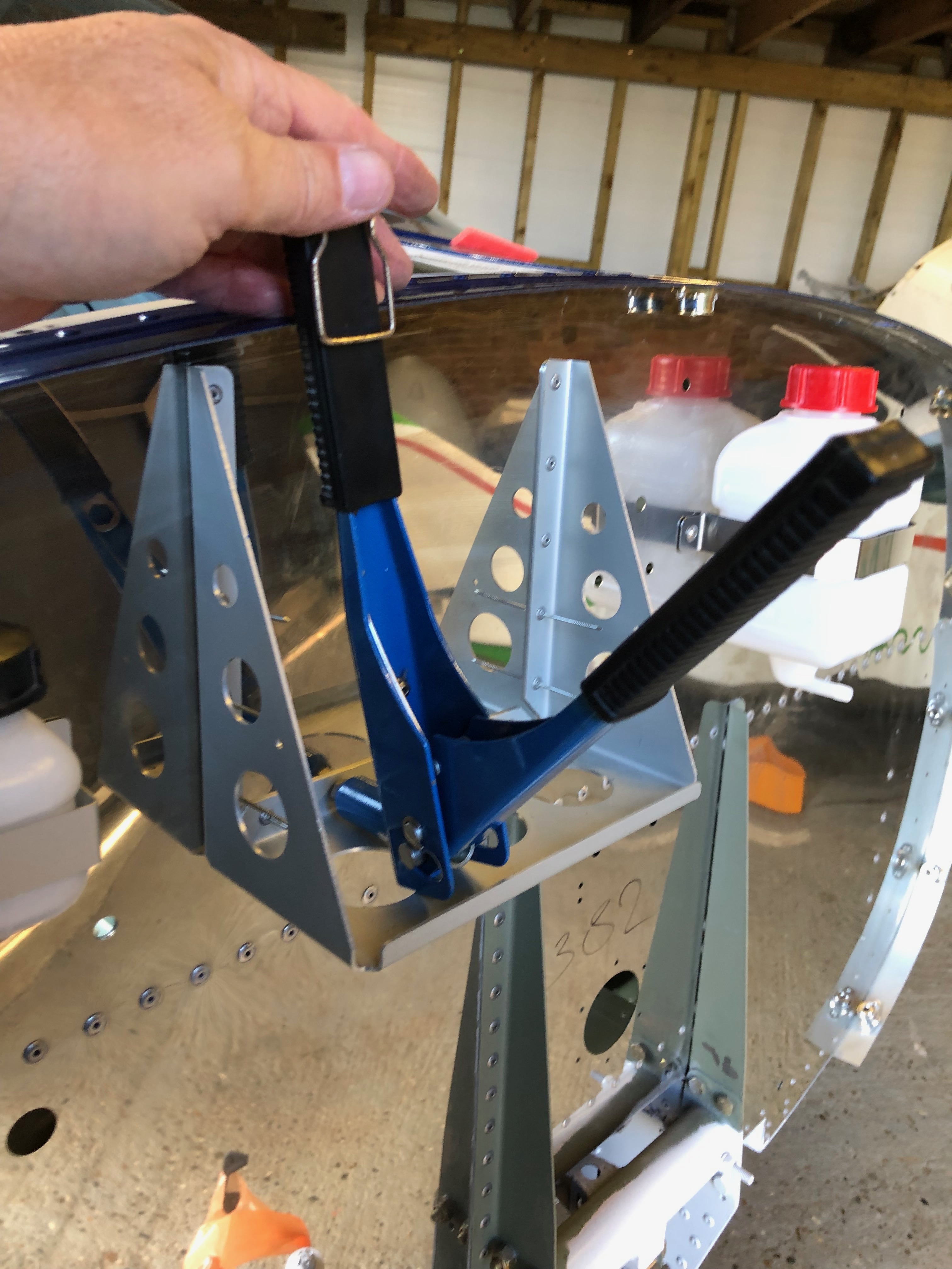
As the battery holder is predrilled I was able to rivet without the use of Clecos.
One of the activities that must be completed before the airframe can be painted is filling the rivets. After scouring the internet I found a video by Alan Radford who demonstrated the method to fill the rivets using SuperFil. I decided to use the same method and sourced the filler from Aircraft Coverings. I spoke to Alex there who despatched it straight away and I received it a day or so later.
Karen using a syringe and SuperFil to fill each rivet
It’s a long job
The filled rivets ready to be sanded
It was very slow going and very hard to squeeze the SuperFil out of the 16g needle. Consulting with Tony Palmer he suggested that we give up on SuperFil as it was just too thick due to the temperature we were working at which was sub 10c. He suggested that we use a resin, mixed with a 1% slow acting hardener which was mixed with talcum powder to give it a thicker consitency. He demonstrated how to mix and fill the resin and we then tried using the new filler. It was an instant success with much quicker progress made.
Some resin and some SuperFil
One by one the rivets were gradually filled.
It was quite chilly!
The slightly proud fills of each rivet which would be sanded down before painting.
It took 3 days to completely fill the rivets.
The next step was to sand down the tops of the resin in preparation for spraying. Using a very fine grit with an orbital air sander made the process very straightforward although it took a day to complete.
I used the air orbital sander to finish off.
Karen used the electric orbital sander just to take the sharp point off the top of the rivets.
A crawler board was invaluable.
and then Karen inspected my work to make sure I didn’t miss any.
Job done!
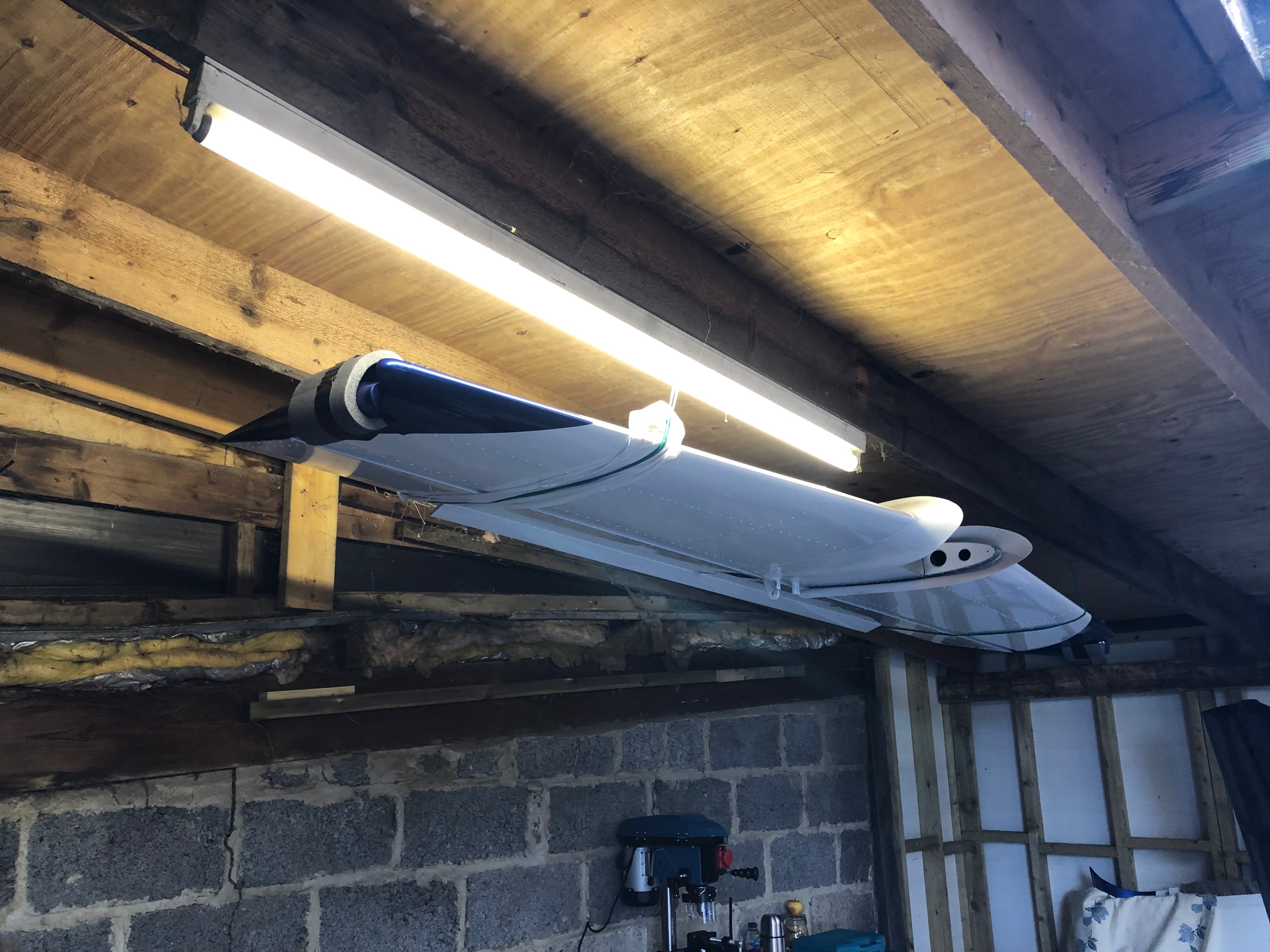
and then the cowls
With all the wings, tailplane and cowls in the van the Fuselage will be loaded onto a trailer for it’s journey to the paint shop.
Following the build of my Bristell NG5 Kit No. 382 Registration G-MLSY