Had a call from Karen tonight from The Handsome Sam to come round for a pint (or two). On ordering my an ‘Old Hector’ Karen delivered it in this! My very own glass with a picture of G-MLSY engraved on it. Not only that but I have my own hook in the pub to hang it on!
What a lucky man I am to have such a wonderful Fiancée.
With all the paperwork now complete and sent to the LAA it’s now a waiting game. As I’m away for the first couple of weeks in September it looks likely that the first test flight will be around the 3rd week in September. Hopefully there won’t be any queries and it goes through quickly.
For now I can just get it out of the hanger and give it a run up and down the runway to further test the engine and systems and then give it a good clean afterwards.
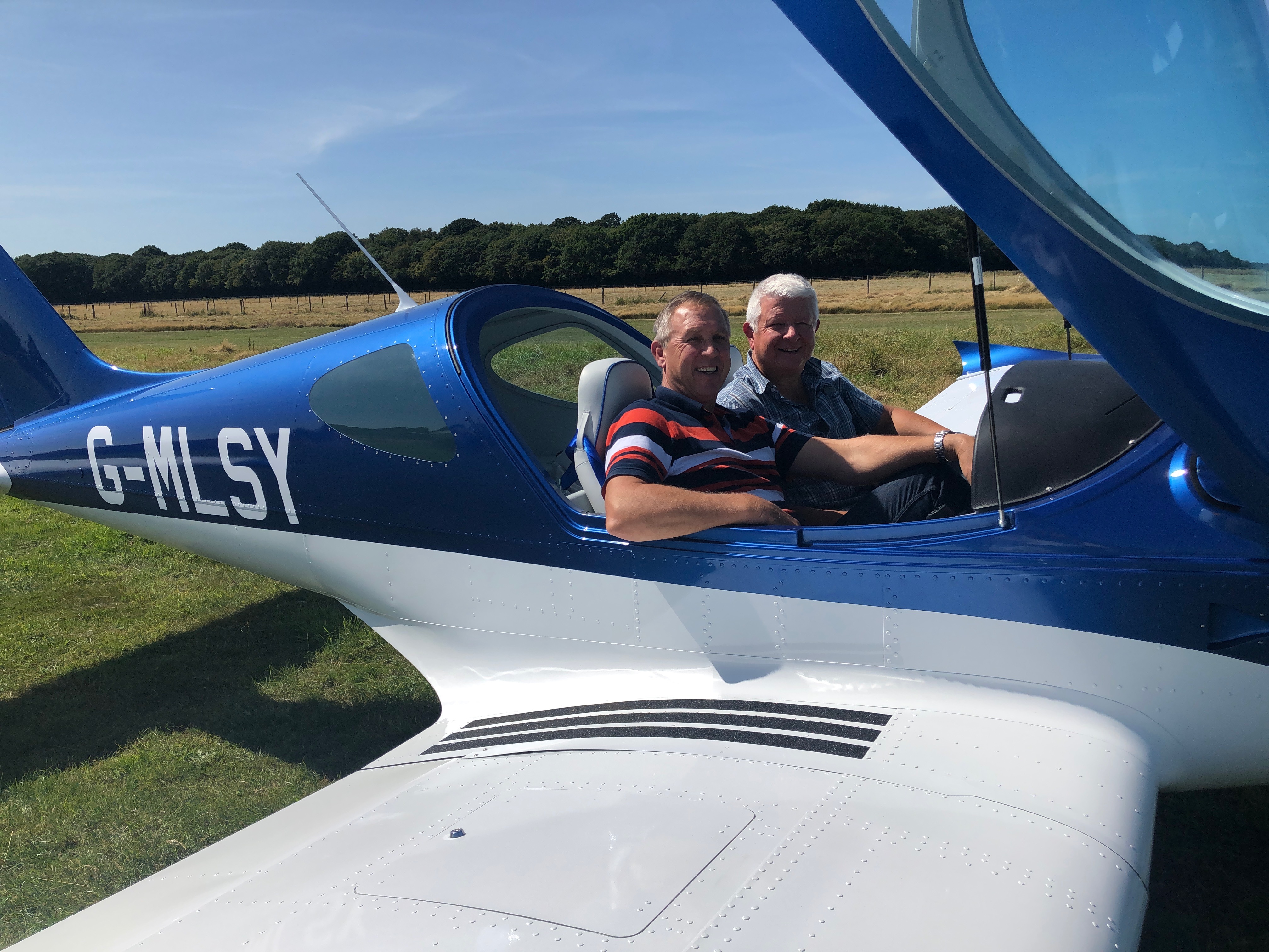
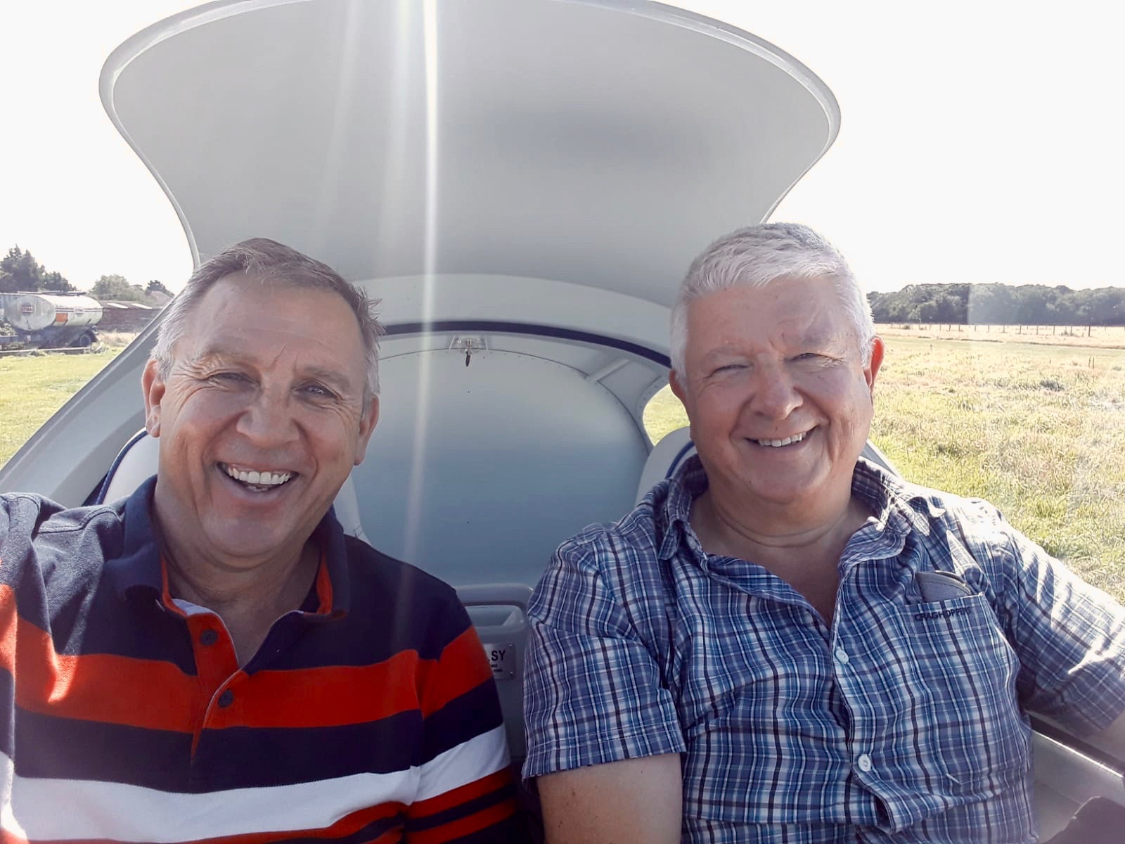
Today, Tom and his Mum came down to visit so Tom got a ‘fast’ taxi run – my first passenger!
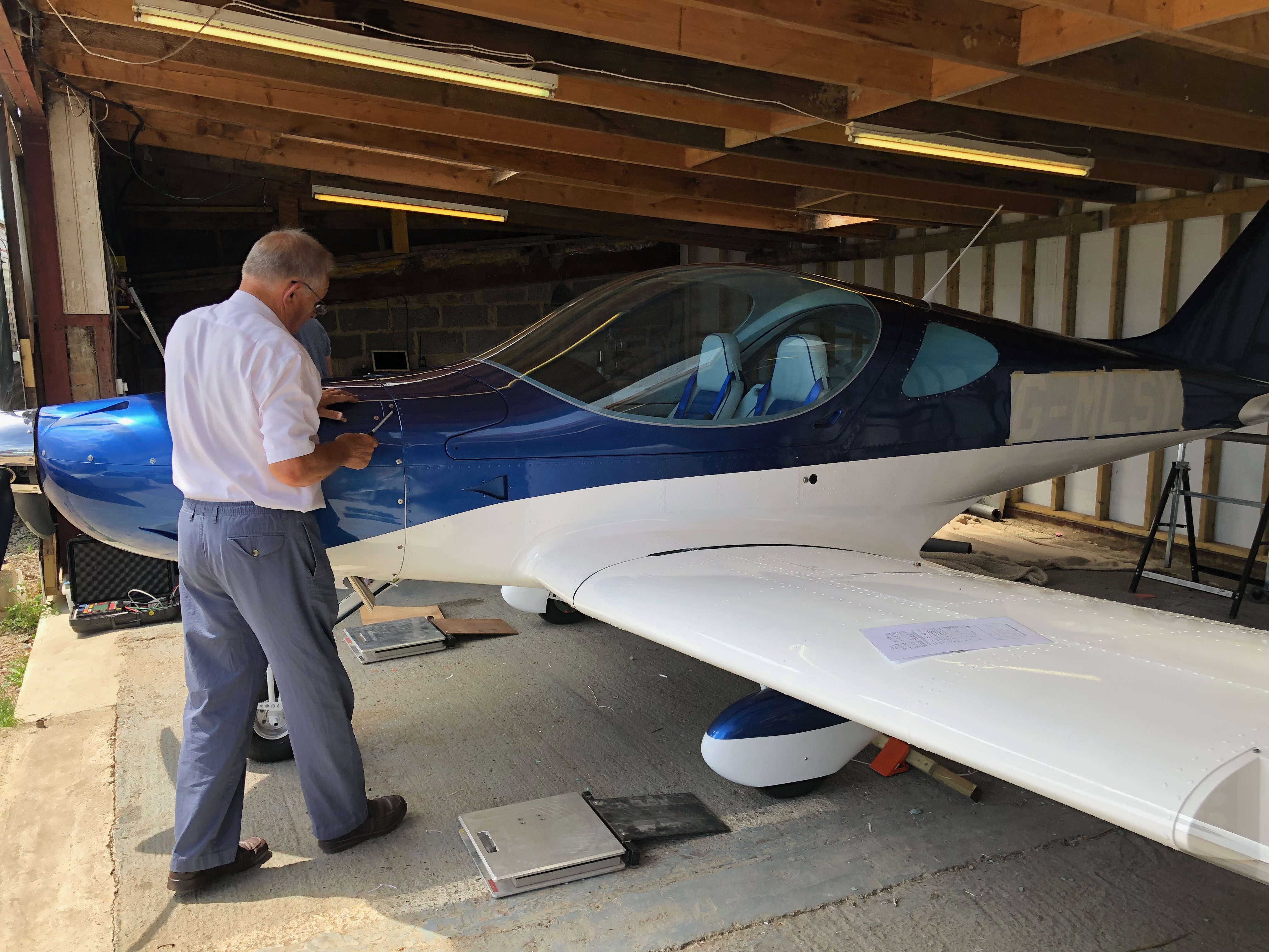
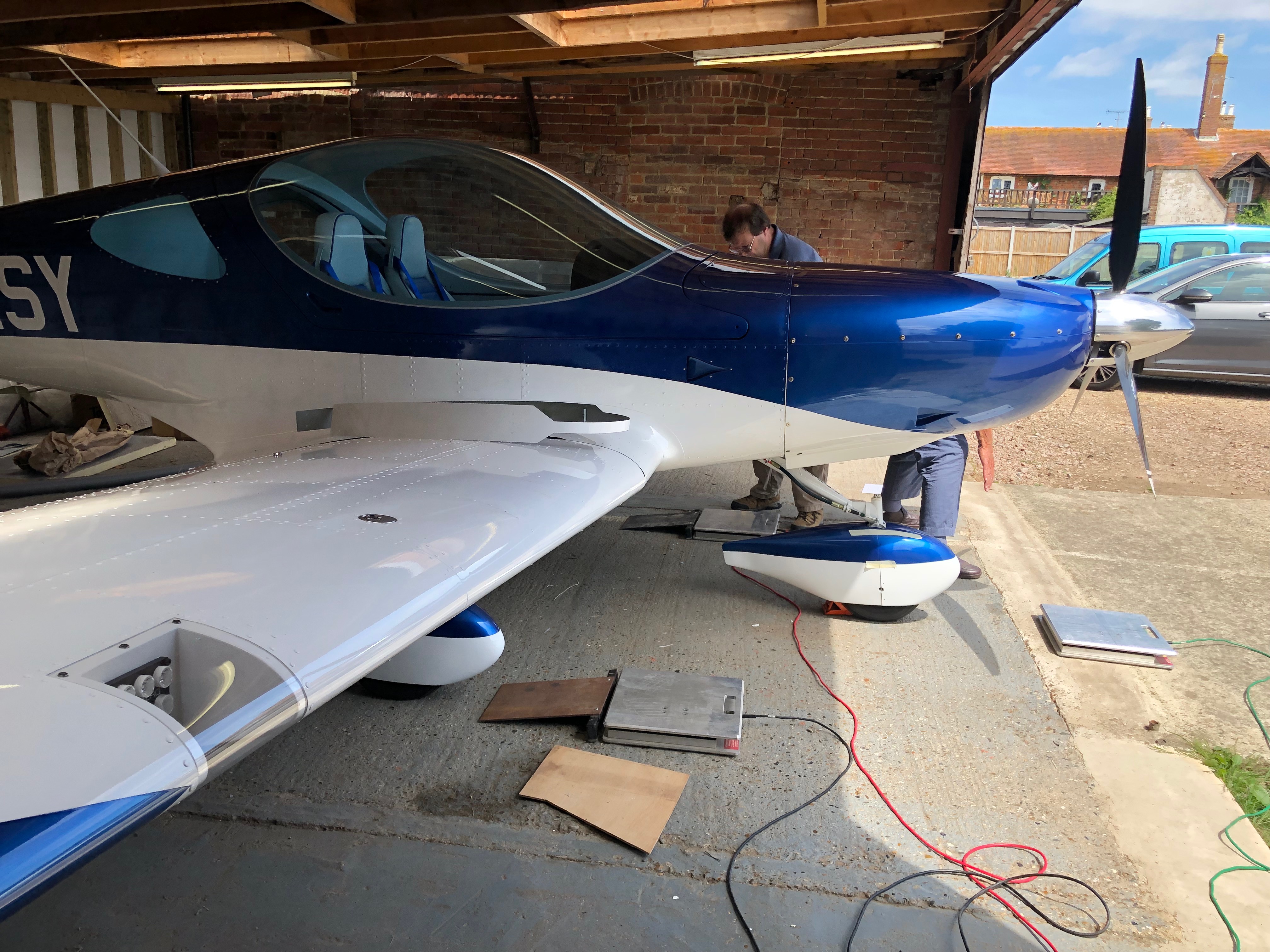
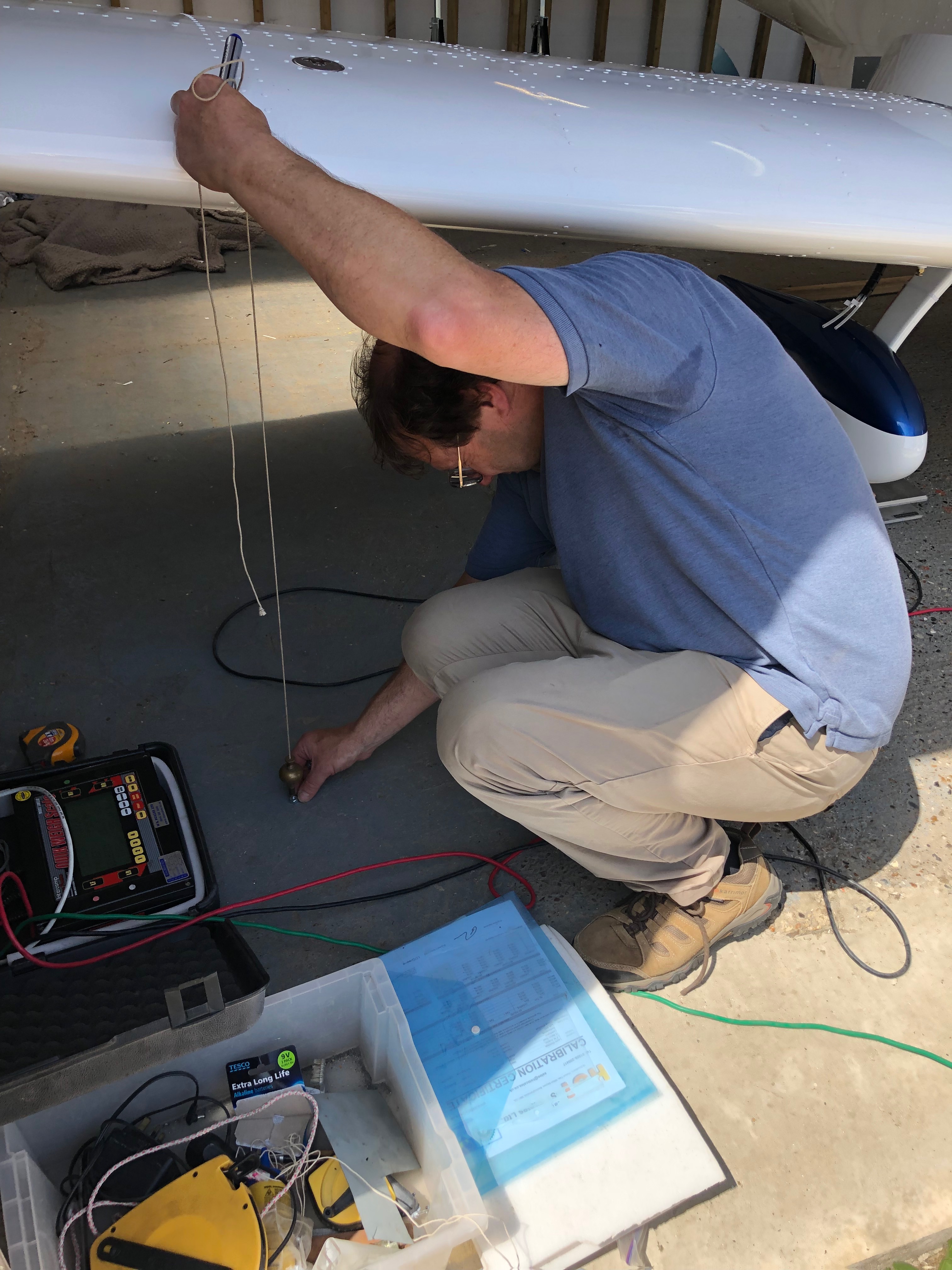
Weighing day today! Pete Thomas a good friend from the London Gliding Club offered to come down to weigh G-MLSY and today’s the day!
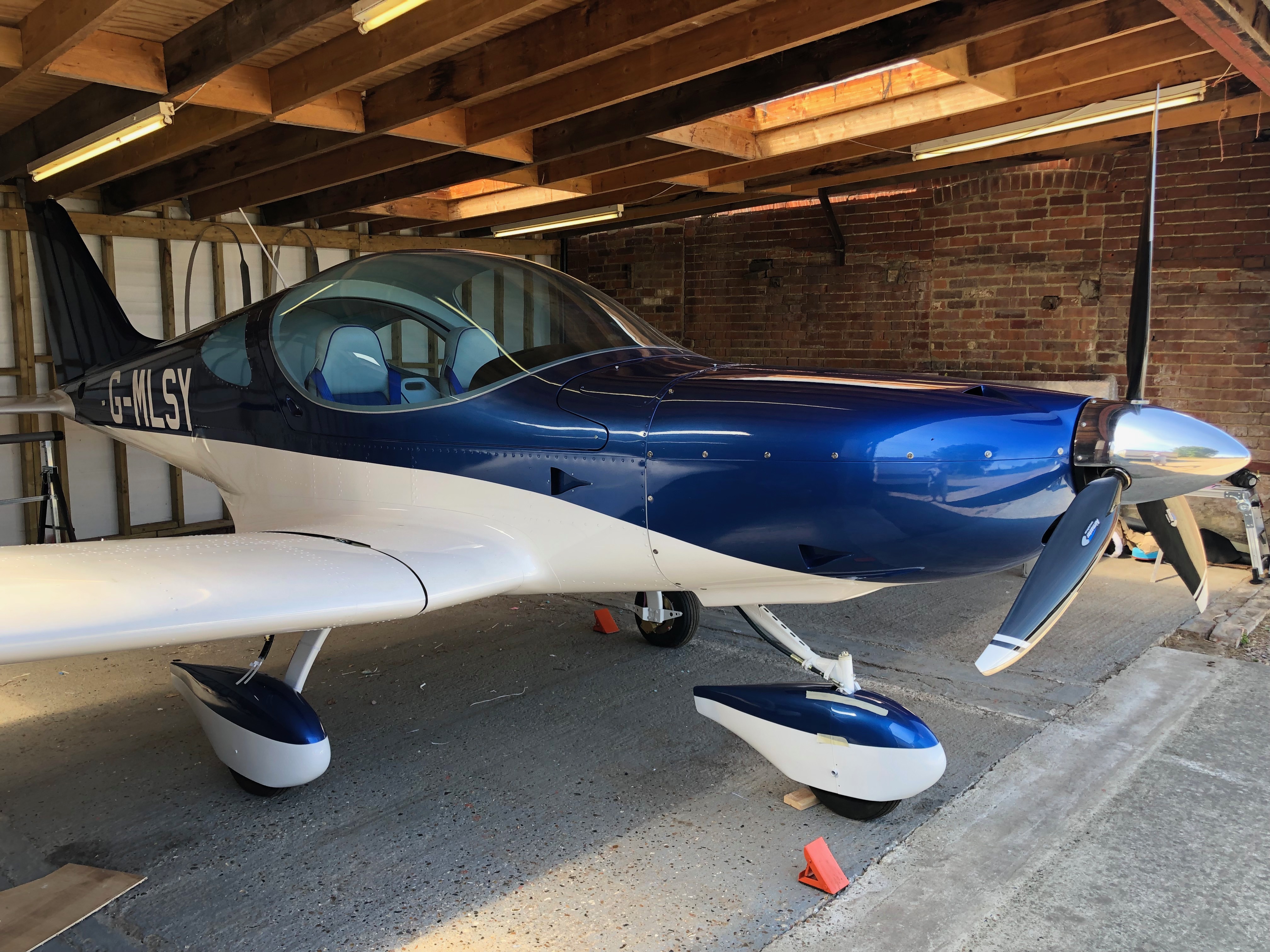
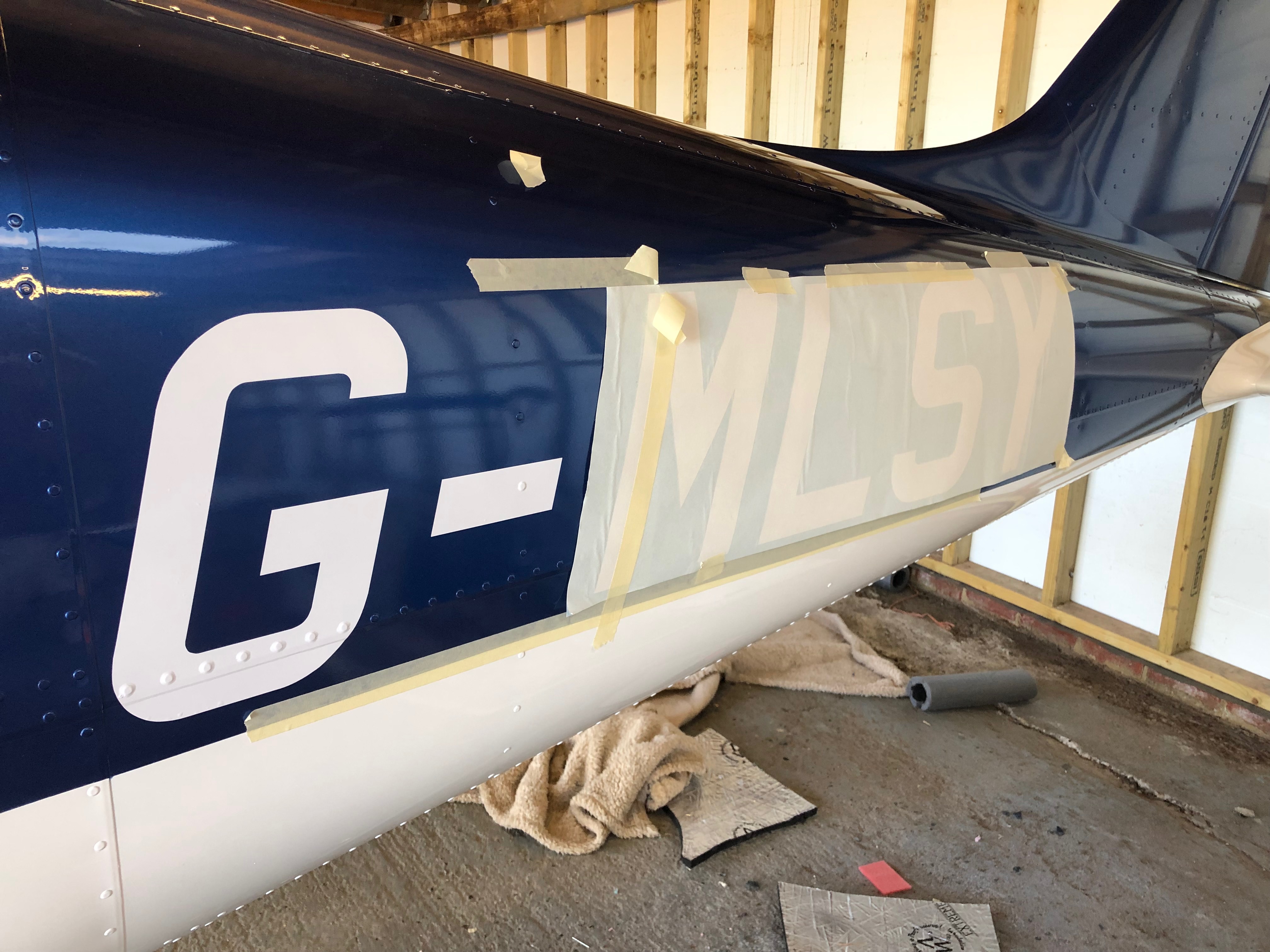
Everything needs to be fitted for the weighing. So the spinner is first and the canopy is lifted on but is won’t be secured yet.Ian as my LAA inspector is overseeing the process to make sure it’s down to the LAA standard.Pete starts the process of laying out the pressure pads.The aircraft has to be exactly level for this so a spirit level is placed across the cockpit and on the cockpit edge and adjustments are made as appropriate. With the aircraft sitting on the pads and levelled both lat and lon weighing can begin.The datum marks have to be calculated so a plumb line is dropped from the reference points and a position marked on the floor. These marks will be used later in the calculations.Pete in action marking the front datum.All done now but a quick pic with everything on before we start to take it off again for the final set of inspections.I’ve done the wing and starboard side registrations but didn’t get chance to go the port side. It’s amazing how quick I did this side compared with the other. At least twice as quick no I know what I’m doing!Now a pick from the left. Looks quite nice.The end of another day. Please with the process so far and not long now to the first engine runs and flight.
Music: Karen was in charge of music so played tracks like ‘I can fix you’ and ‘All right now’ Very funny Karen!
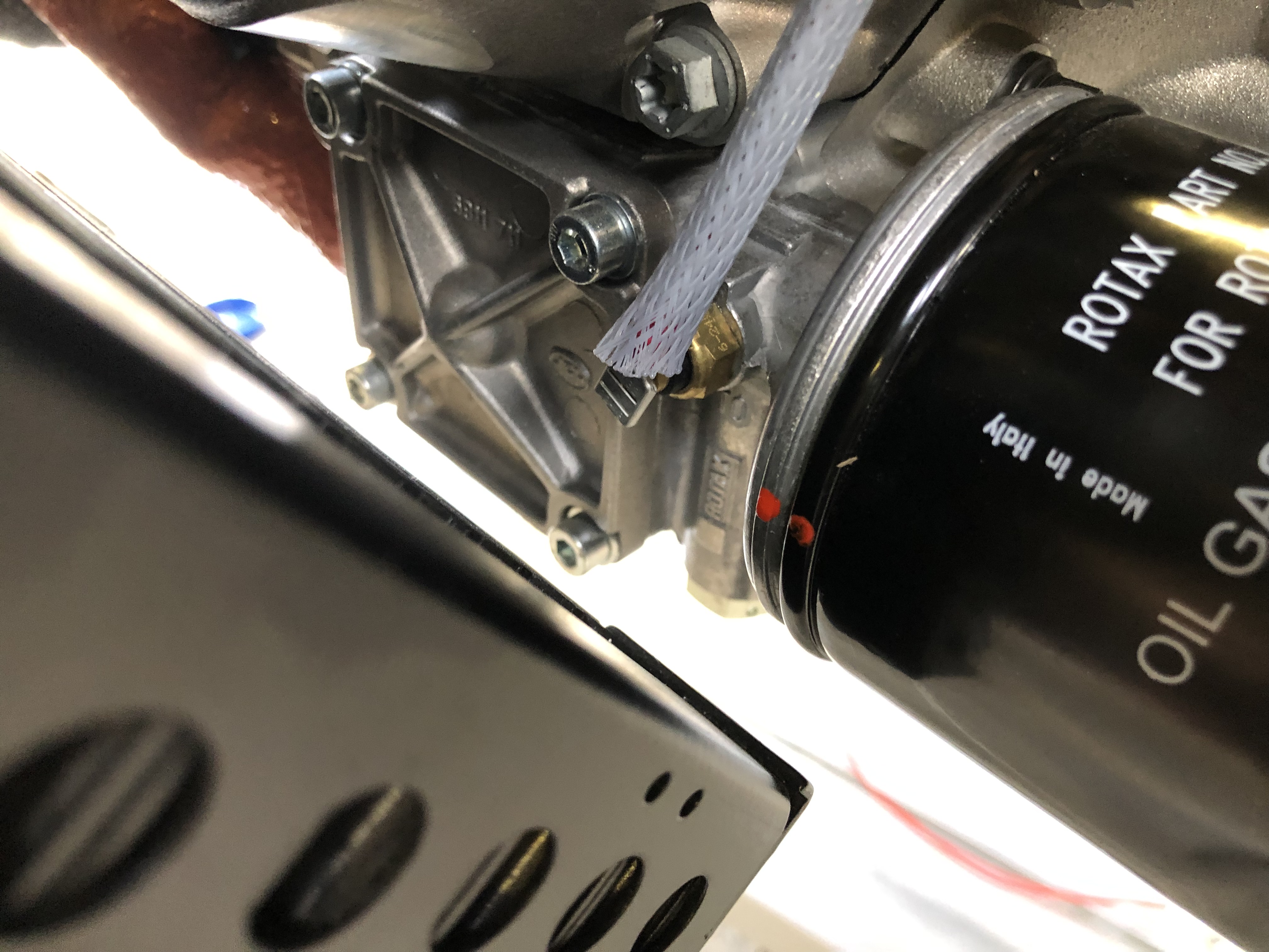
As I was packing up last night I noticed a wet patch under the front tyre. When I investigated I found a very small leak from two of the modified water pump pipes. Unfortunately there was no way round it, the pump will have to be removed, the pipes removed and resealed. A call to Tony Palmer revealed that there had been other cases of leaking and was put down to a loose fitting pipe. The solution is to cut the thread slightly further down the pipe so it’s a tight fit when at the correct angle. Karen came along to give me a hand.
The slight leak. Can’t ignore it, if it leaks with no pressure in the system it’ll certainly leak a lot more when the engine is running.So the coolant needs to be drained……so I can remove the pump. I’ve removed the pipes from the water pump, cleaned the thread but now have to order an 18mm die. I’ll use the die to cut a slightly longer thread.As I can’t do anymore on the water pump I though i’d Loctite the12 set screws, 4 on each blade and…… add some Torque Seal on the set screws to allow any movement to be identified. I know have to wait for the Die to come before I can finish off the water pump.
Music: Fleetwood Mac – Saw them in concert at Wembley last night. A little treat from Karen – Absolutely fantastic!
The wiring continues, after each circuit is wired up a check to see if it’s working as expected. All good so far!
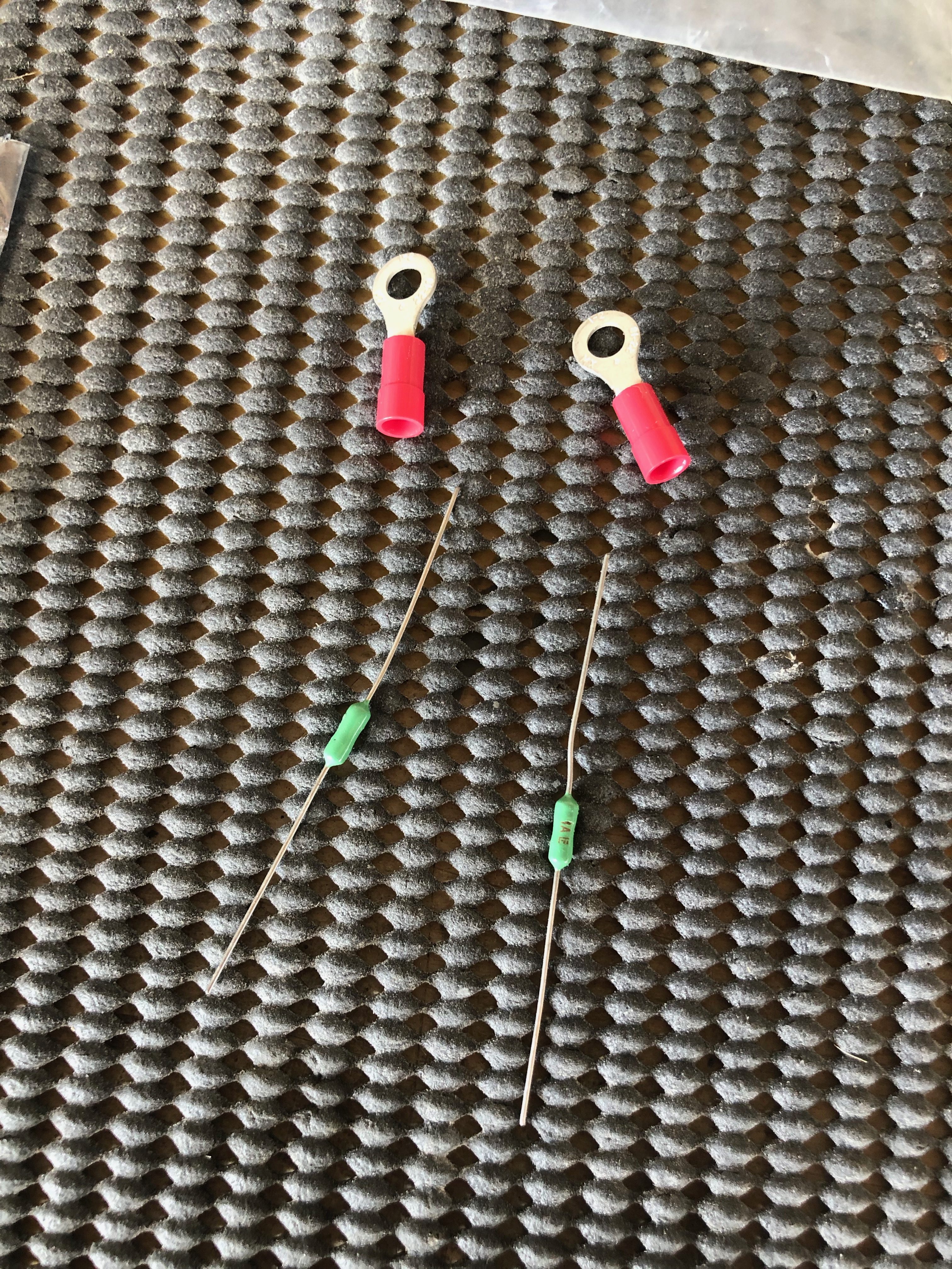
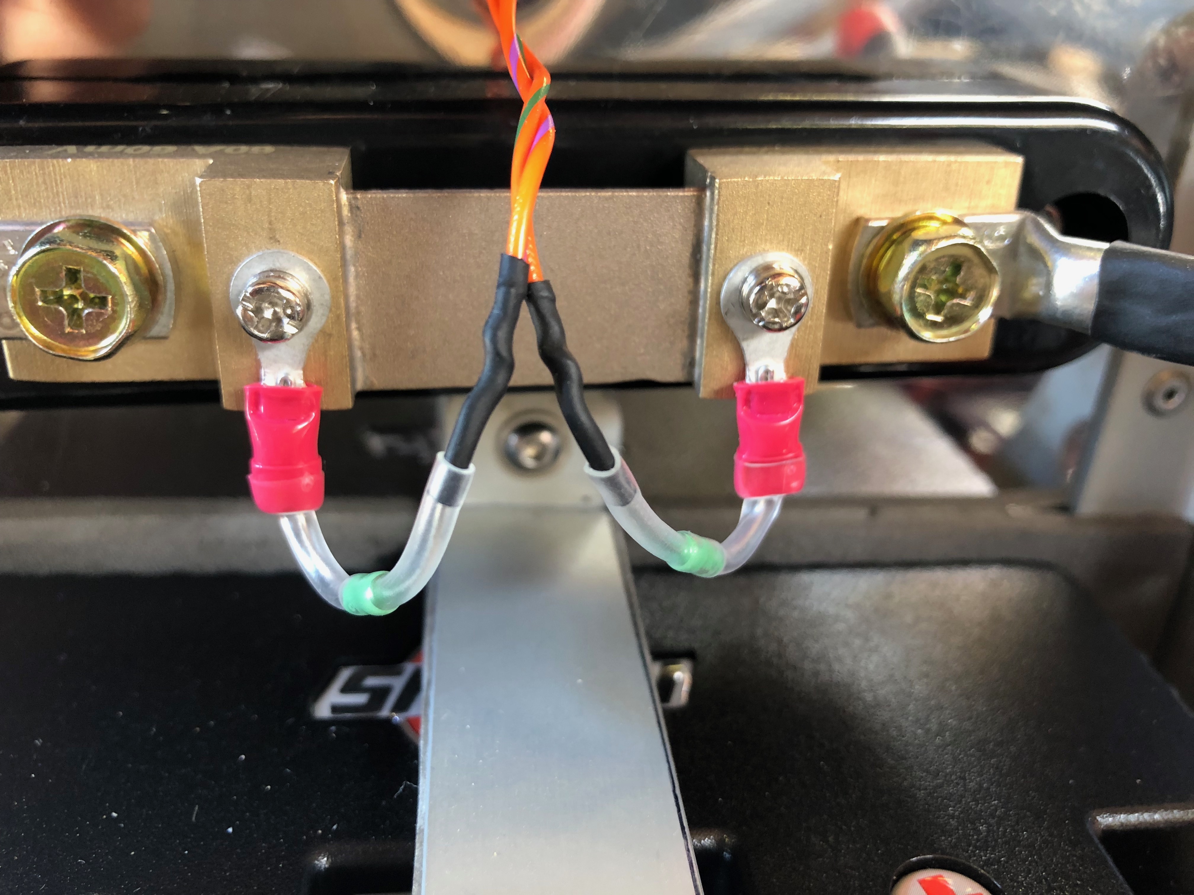
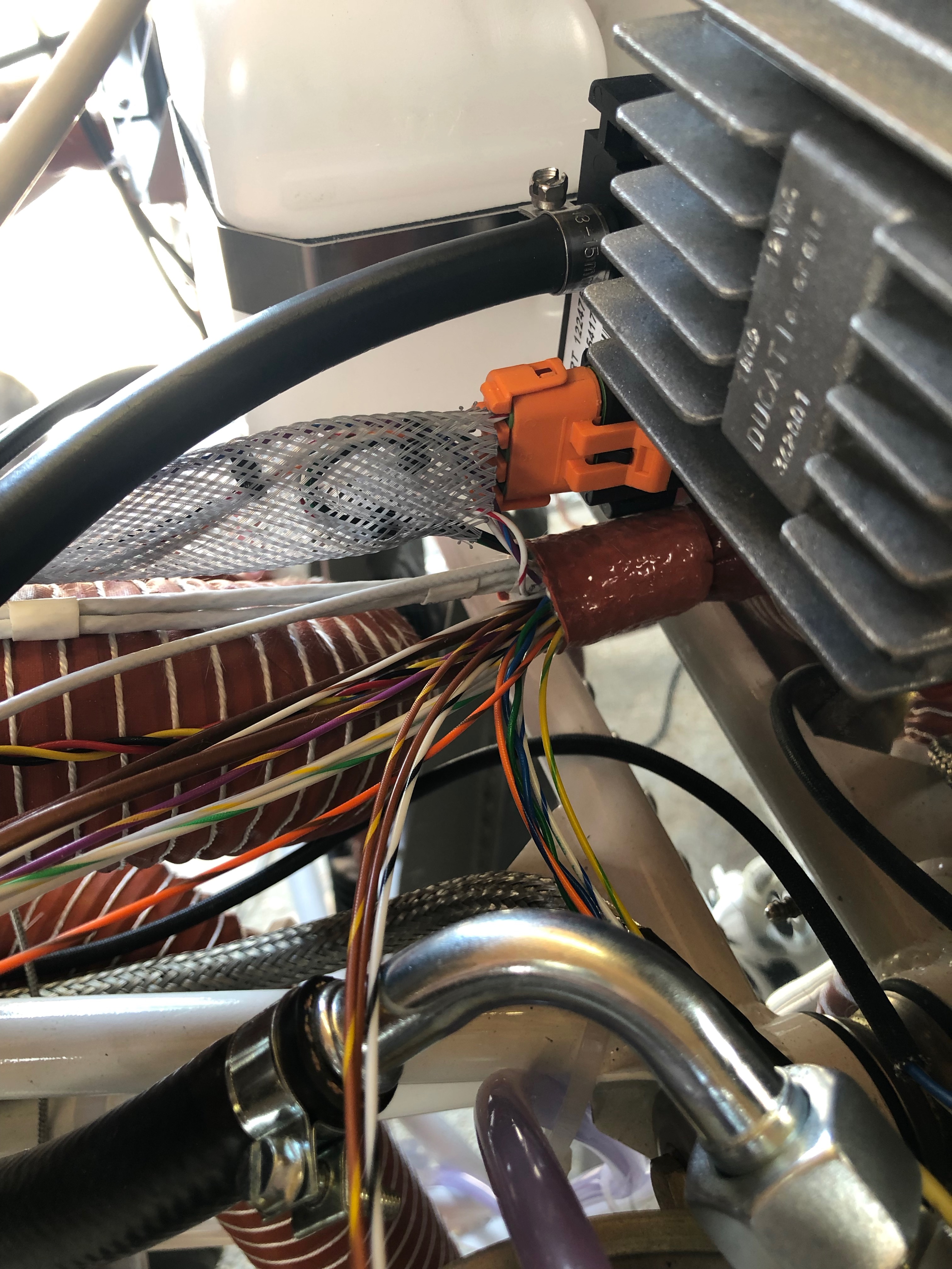
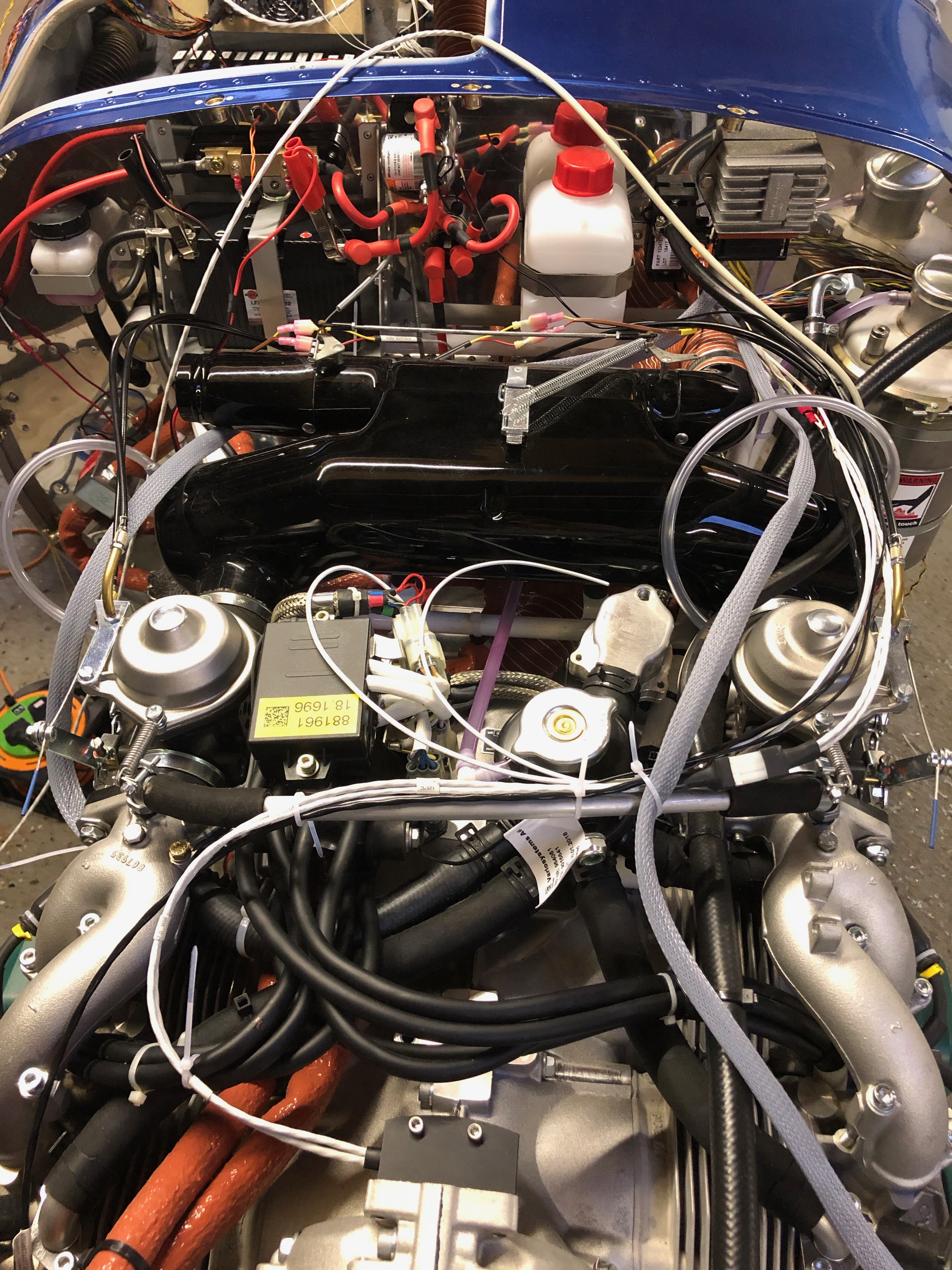
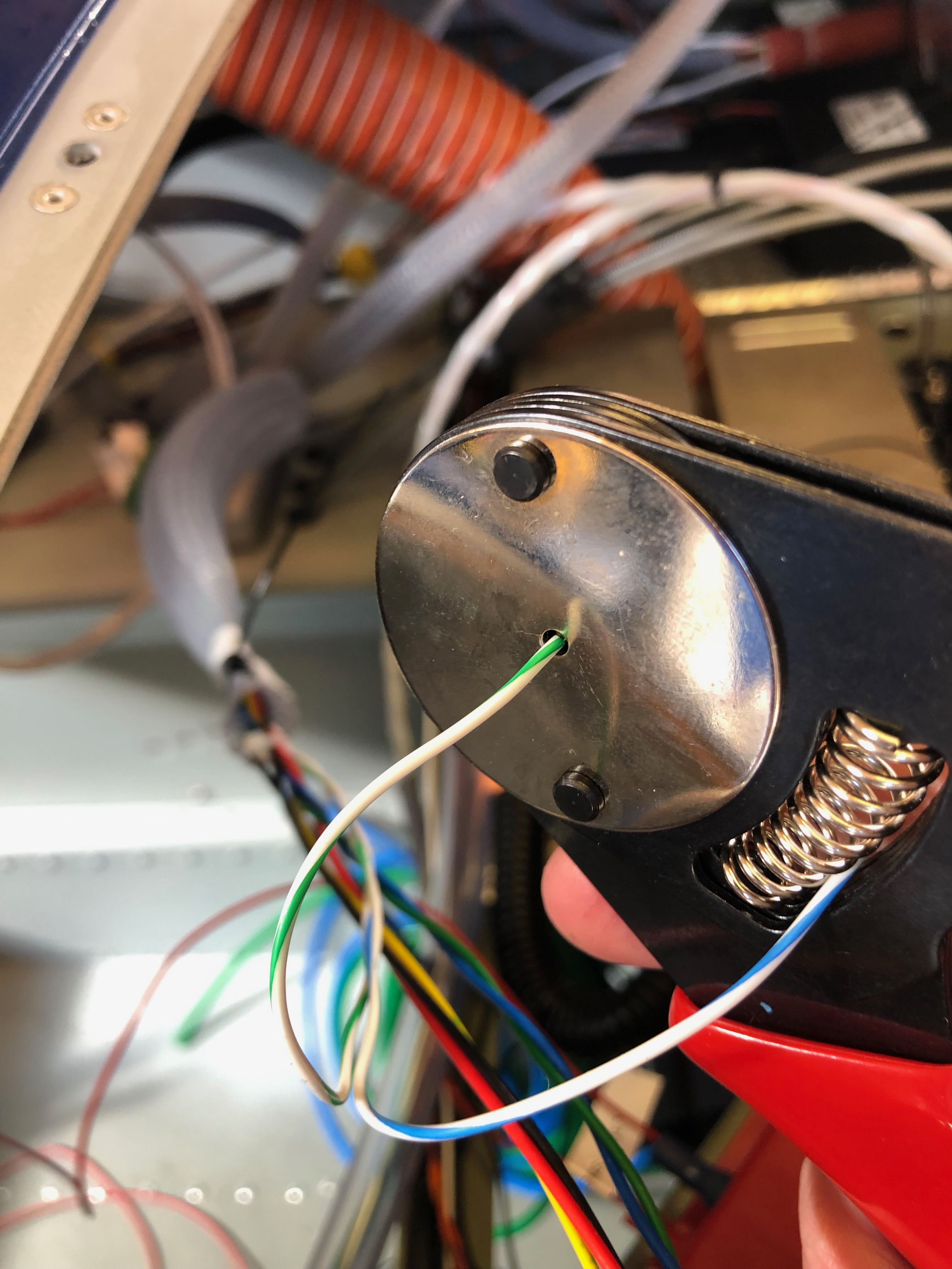
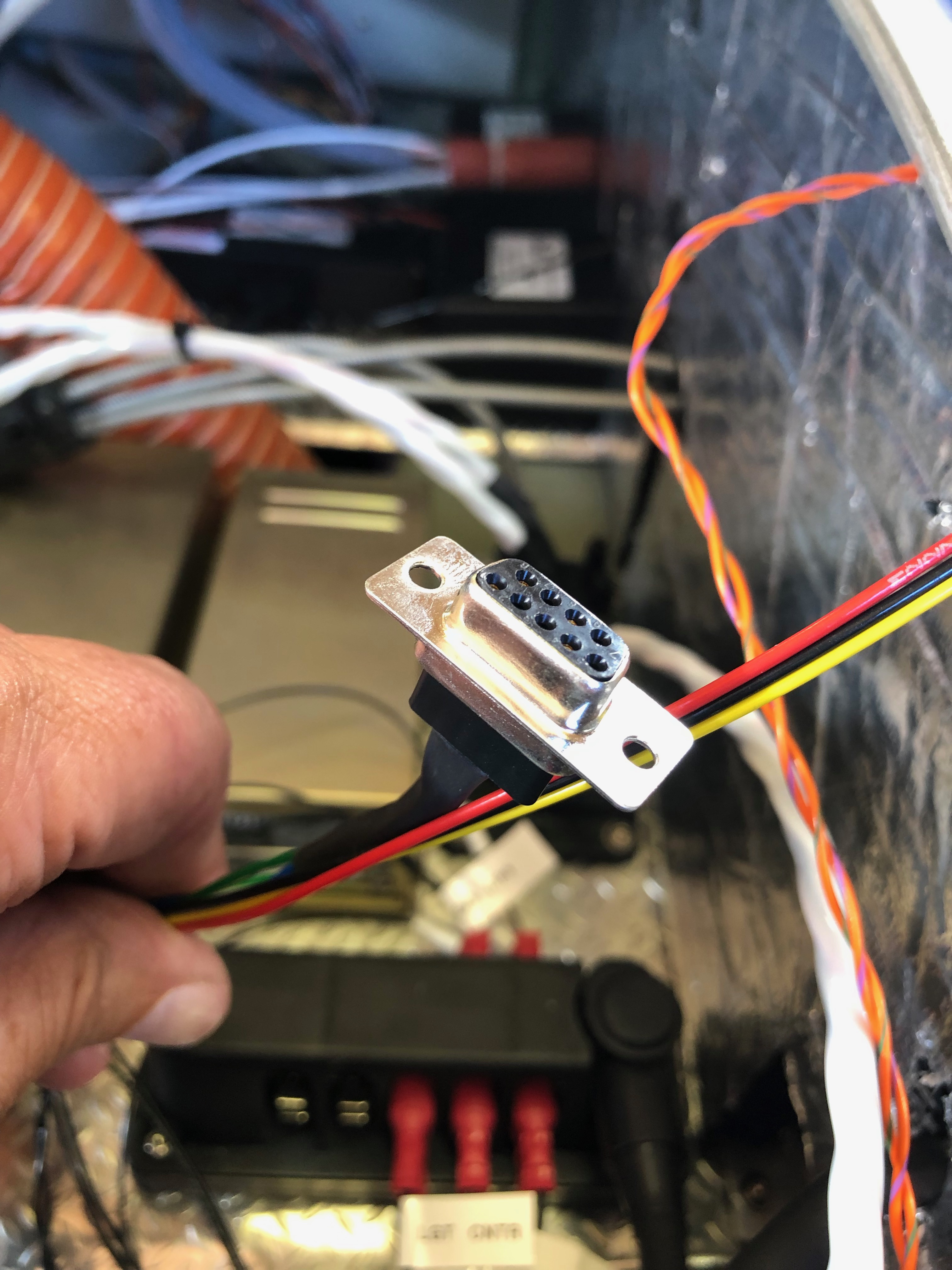
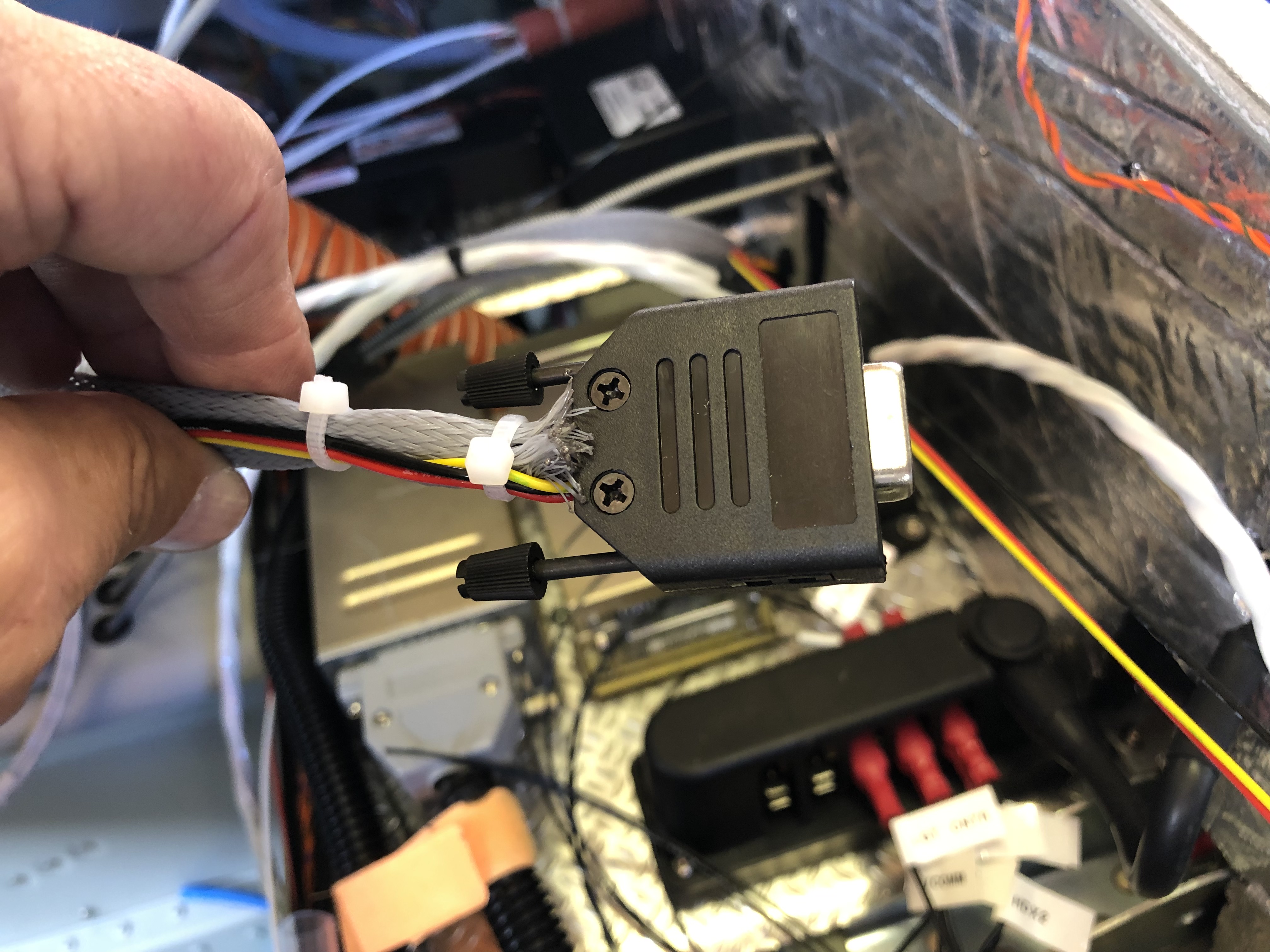
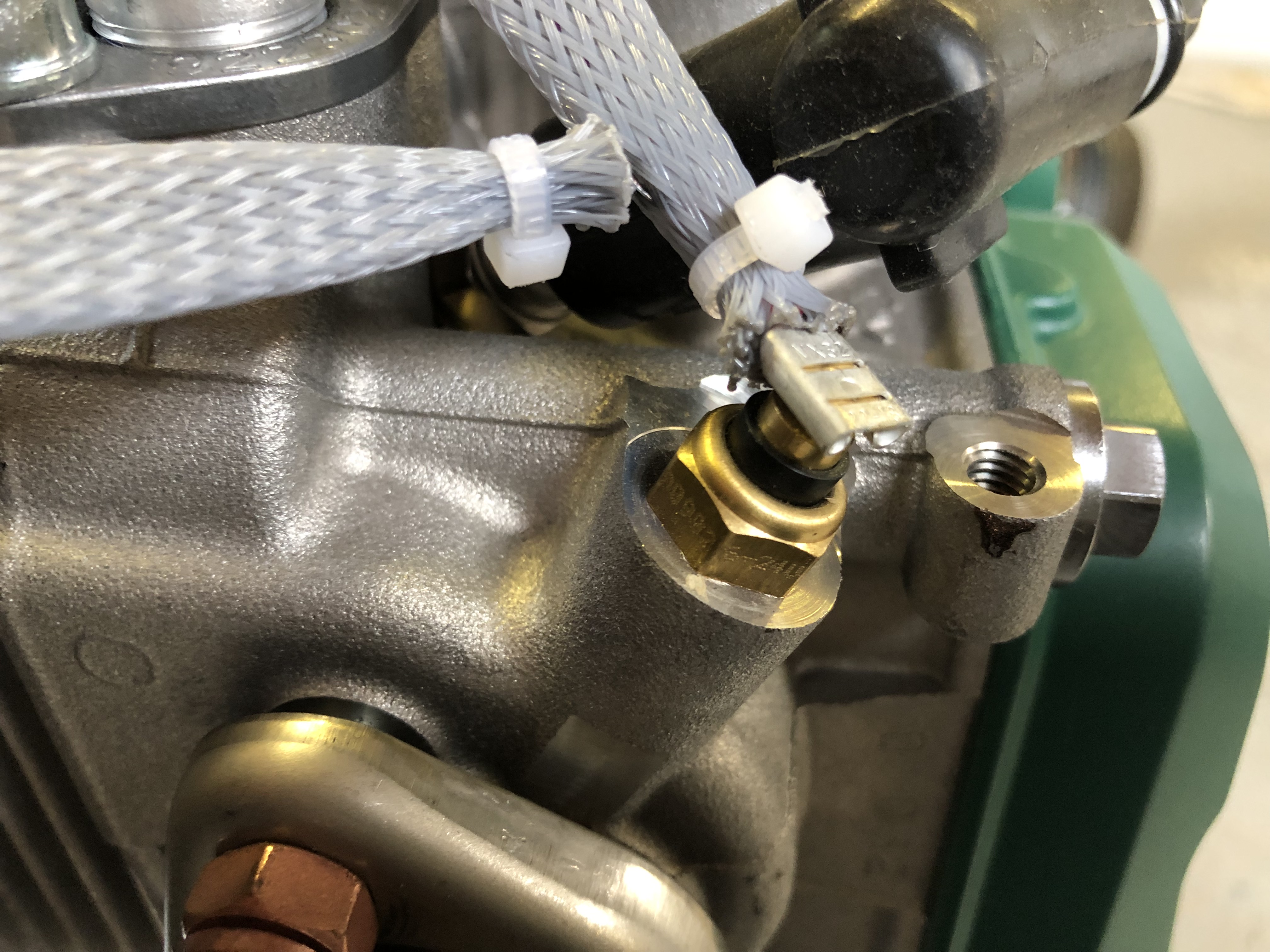
As mentioned previously I need to protect the SkyView from a surge from the Amp Shunt so I’ve purchased some 1 amp inline fuses. They are very small…… and make for a very neat protection solution when positioned inline.With all the wires ‘under the bonnet’ it’s difficult to make it all tidy… …but I layout all wire first to see where best to route them before trimming to correct length and terminating. All these will need to be secured too with stand-offs as required.The servo looms are next. I’ve installed the looms as far as the cockpit and now need to terminate each wire and make up the connector. It requires crimping the pins on each wire with a 4 way crimper.After crimping they are inserted into the D9 block……and the backshell is added. Fairly straightforward but you have to make sure that the crimps are secure. There are two of these, one for roll and one for pitch. Once made up they are plugged onto the SkyView network hub.Next up is to finish off the engine sensor connections. The correct pinout from the D37 connector is identified and the wire routed as described before trimming to the correct length and terminating. In this case a uninsulated spade connector that slips over the sensor connector. This is the LH CHT sensor……and the oil temperature sensor.A quick check that everything is working. The CHTs, EGTs, Oil Temp, Fuel pressure, Oil pressure, Voltmeter, Ammeter and autopilot have now been completed and work as expected.
Music: Elton John who we’re seeing in Prague next week!
Haven’t got a full day today but thought I could install some of the cables that I received yesterday in the post and the tail strobe.
The Pitot power cable requires quite a heavy duty wire as it can draw up to 10 amps so for the run from the wing to the power it requires 12awg. So the power cables and sensor wires need to be made up into a simple wire loom. I’ve just used some heat shrink tubing along the length.So this needs to be run into the wing conduit.Using a draw wire to pull the wire through I’ve used a piece of heat shrink tubing to join them together.And then pull it through this conduit and hope the heat shrink works which it did.Next is to run the strobe power and sync cable from the tail to the front of the fuselage. Again there is a conduit that makes it relatively painless to do but there is a already a trim control wire running in the conduit so it’s a little tight to feed through.The is the strobe that will be put on the tail fin.The mounting holes need to be drilled using a step drill.And M3 rivnuts and cap head screws are used to secure but I’ve run out of time so will finish off tomorrow.
A few jobs whilst Andy is still here to help including the internal trim panels, OAT sensor, bleeding the brakes and pitot system installations.
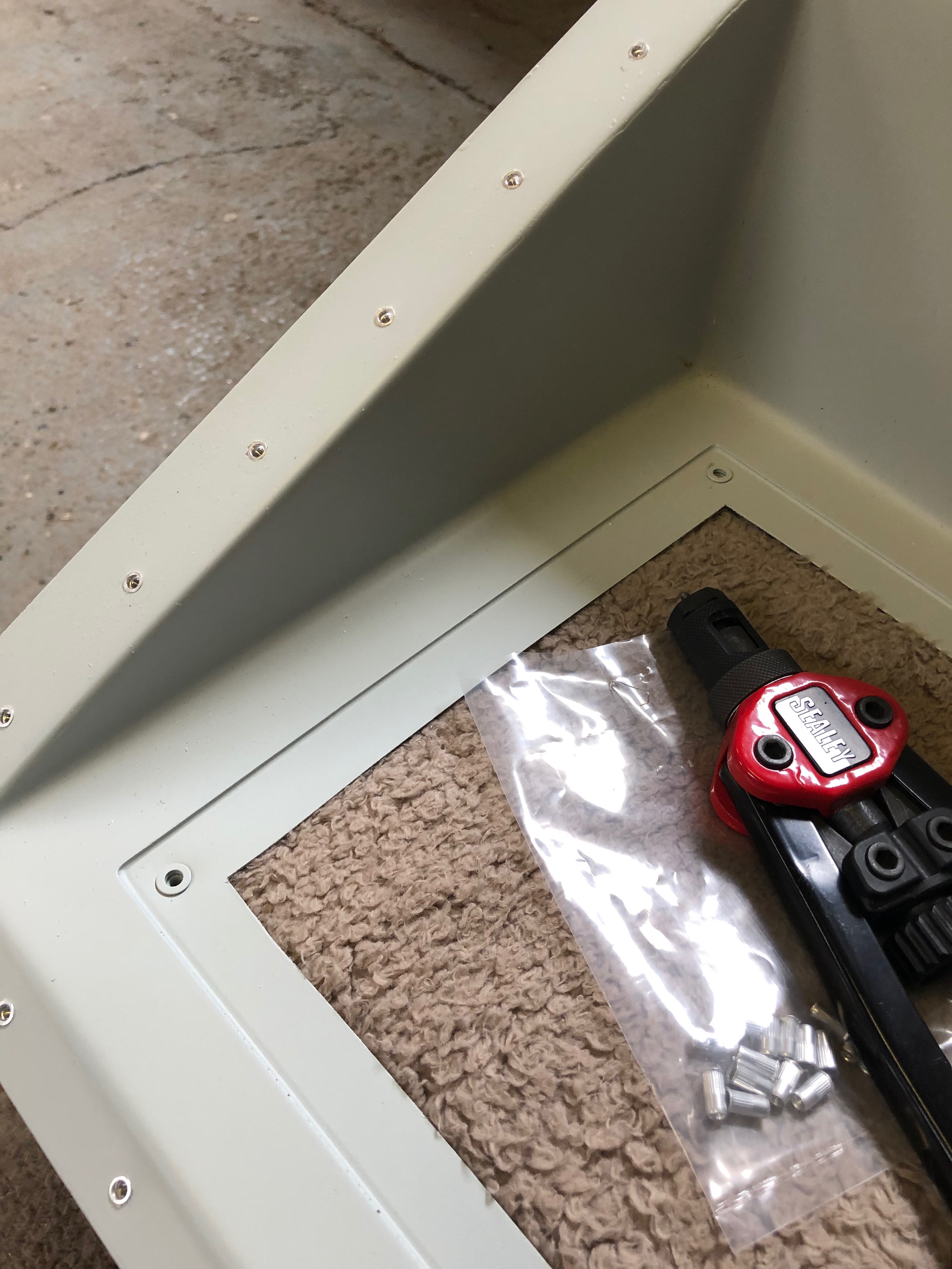
The rear panel in normally riveted into the aircraft and has two access panels cut in with covers. I thought it would be a better idea if it was removable so decided to use 3mm screws and rivnuts to secure it instead. First job drill the 5mm hole for rivnuts.
The install the 37 rivnuts in the rear panel…
and 8 along this panel.
The finished job which looks quite good.
The supplied OAT cable is several metres long but I’ve decided to mount it close to the ADAHRS unit so I shortened it out by cutting some wire out of the the middle of the cable and soldered together which removes the need to crimp new ends on.
The OAT sensor is fitted from below and secured with a nylon nut and washer. I’ve used a bit of silicon to make it even more water tight from below before fitting.
The finished installation needs to be within 2 degrees of level in all planes so once the aircraft is finished I may have to shim the unit.
After bleeding the brakes I have two very small air bubbles left in the brake lines that need to be purged. The normal method didn’t work so thought using an electric pump might work. The whole thing turned into a disaster. The first attempt resulted in the electric pump sucking in air. The second attempt resulted in the pump forcing off the pipe. Then on the third attempt the pump failed after 5 seconds of continuous use. I gave up! will try again another time…
Moving onto the pitot installation. I’ve purchased an electrically headed pitot that needs power to it so I need to run power to the unit. There is conduit in the wing so will use this but it’s difficult to get to.
The only place I can easily mount the heater power unit is on access cover but the unit is just little bit big for the access hole so I had to cut the corners of the mounting bracket.
It’s secured onto the of the access panel with M4 screws, washers and nylocs.
It’s a perfect fit..
The view from the underside.
just needs to be connected and wires run up the conduit.
It’s a very tight fit but need to get my arm into the access panel to get to the conduit.
30/12/2018 – Karen found a nearly new Aldi tool chest for sale. So a quick trip up to Hornchurch to pick it up and now installed, after cleaning, in the workshop. Just the job!
Following the build of my Bristell NG5 Kit No. 382 Registration G-MLSY