Category Archives: Electrics

Monday 17th June 2019

Music: Fleetwood Mac – Saw them in concert at Wembley last night. A little treat from Karen – Absolutely fantastic!

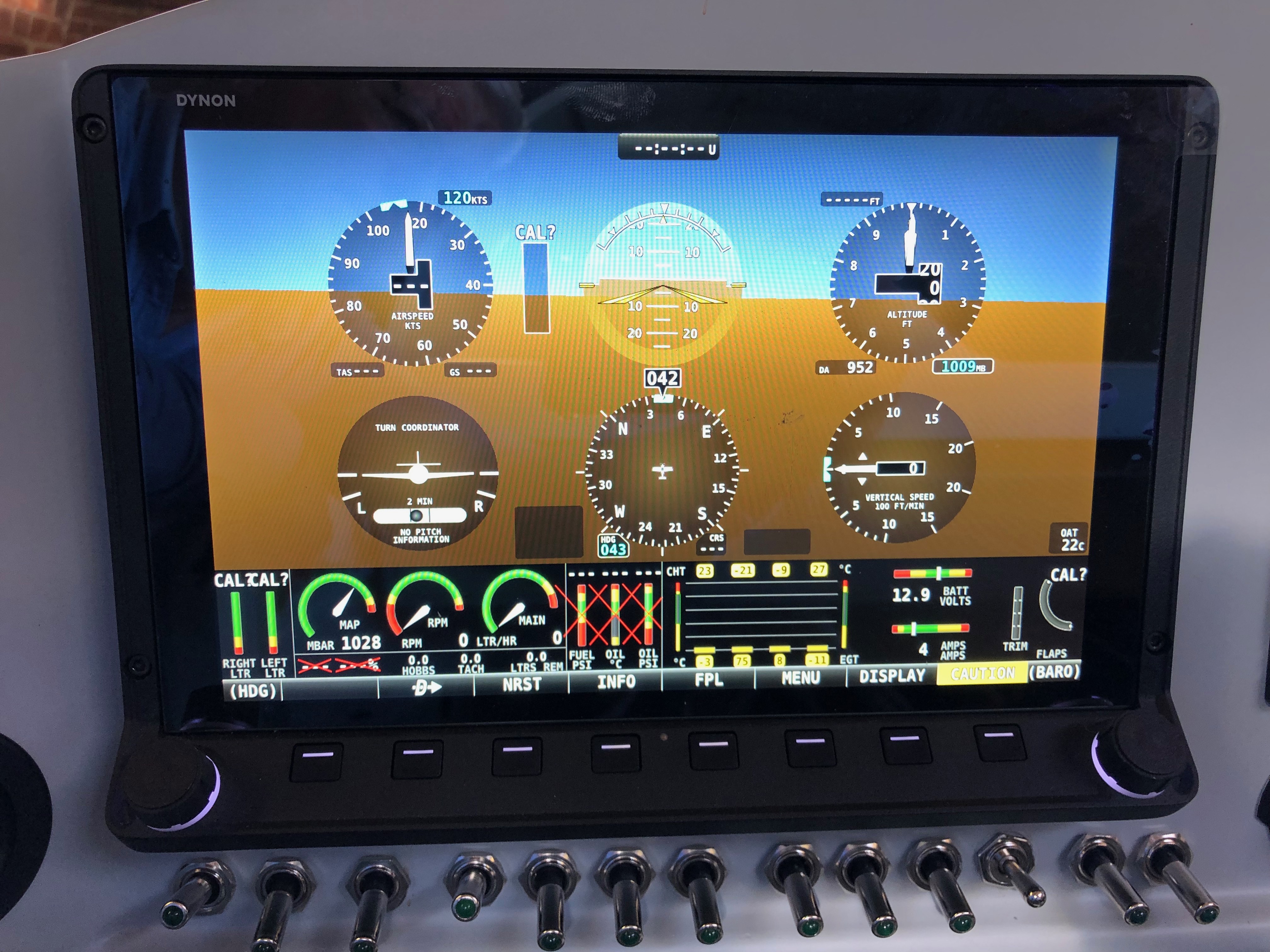
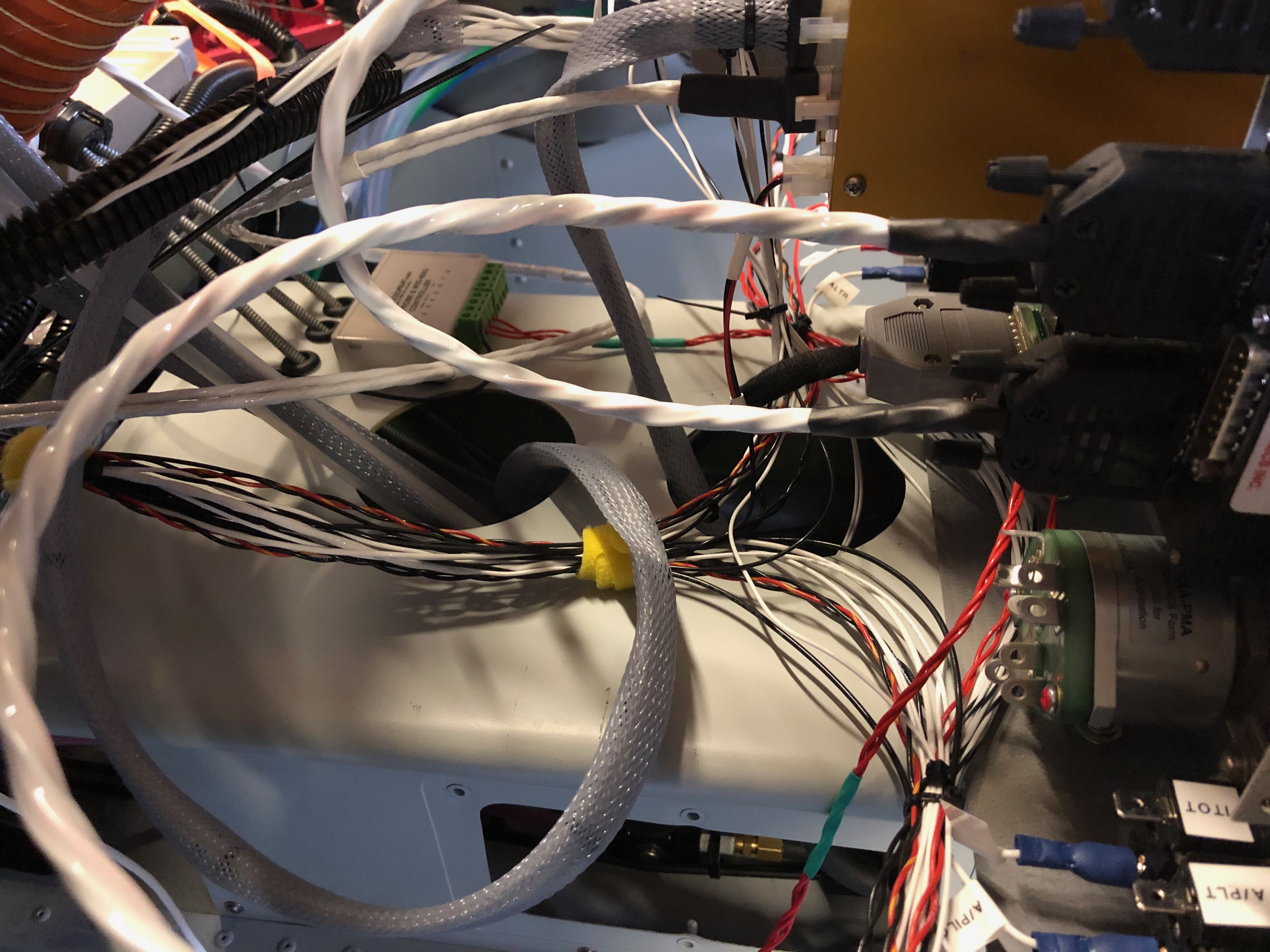
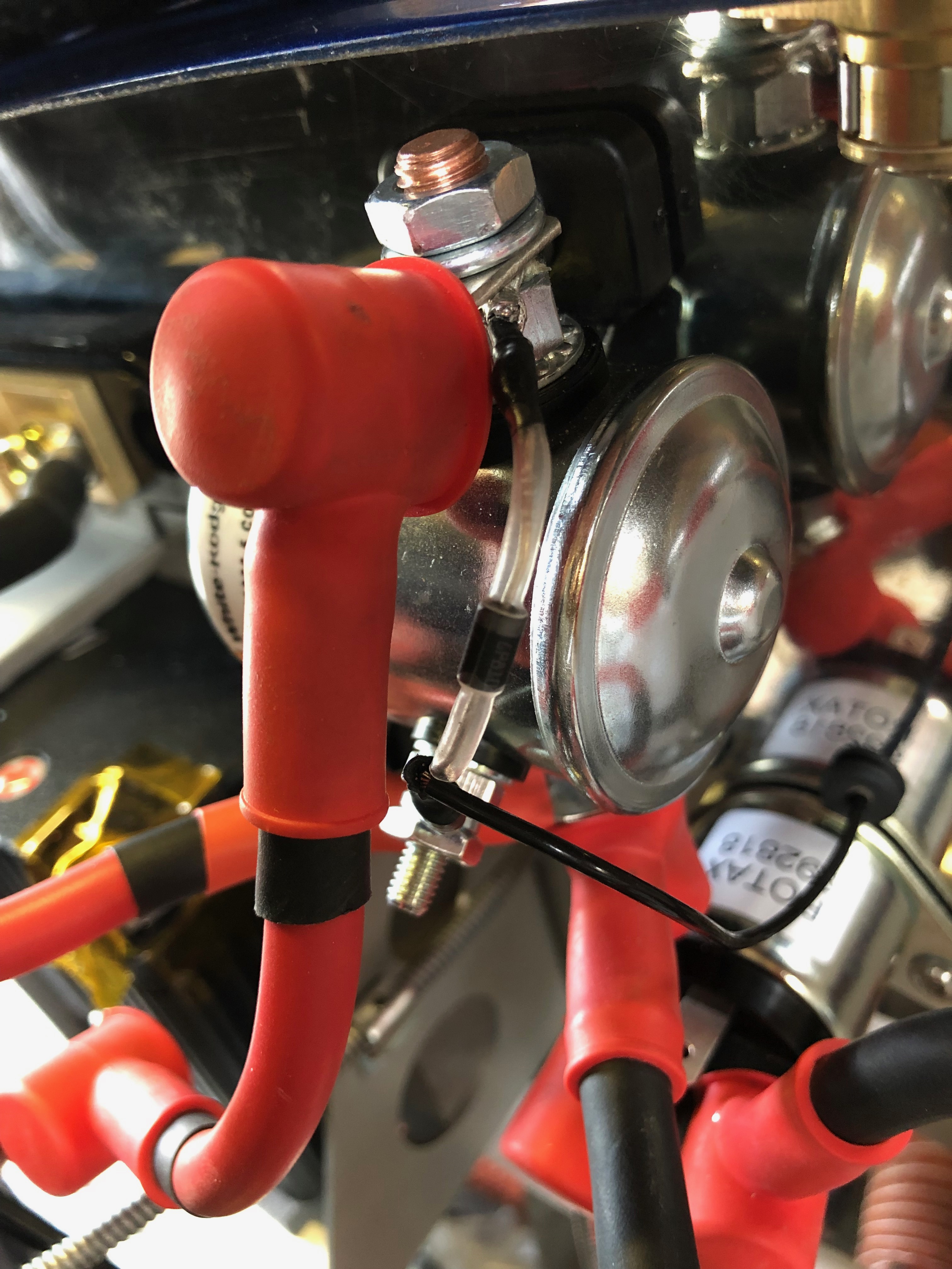
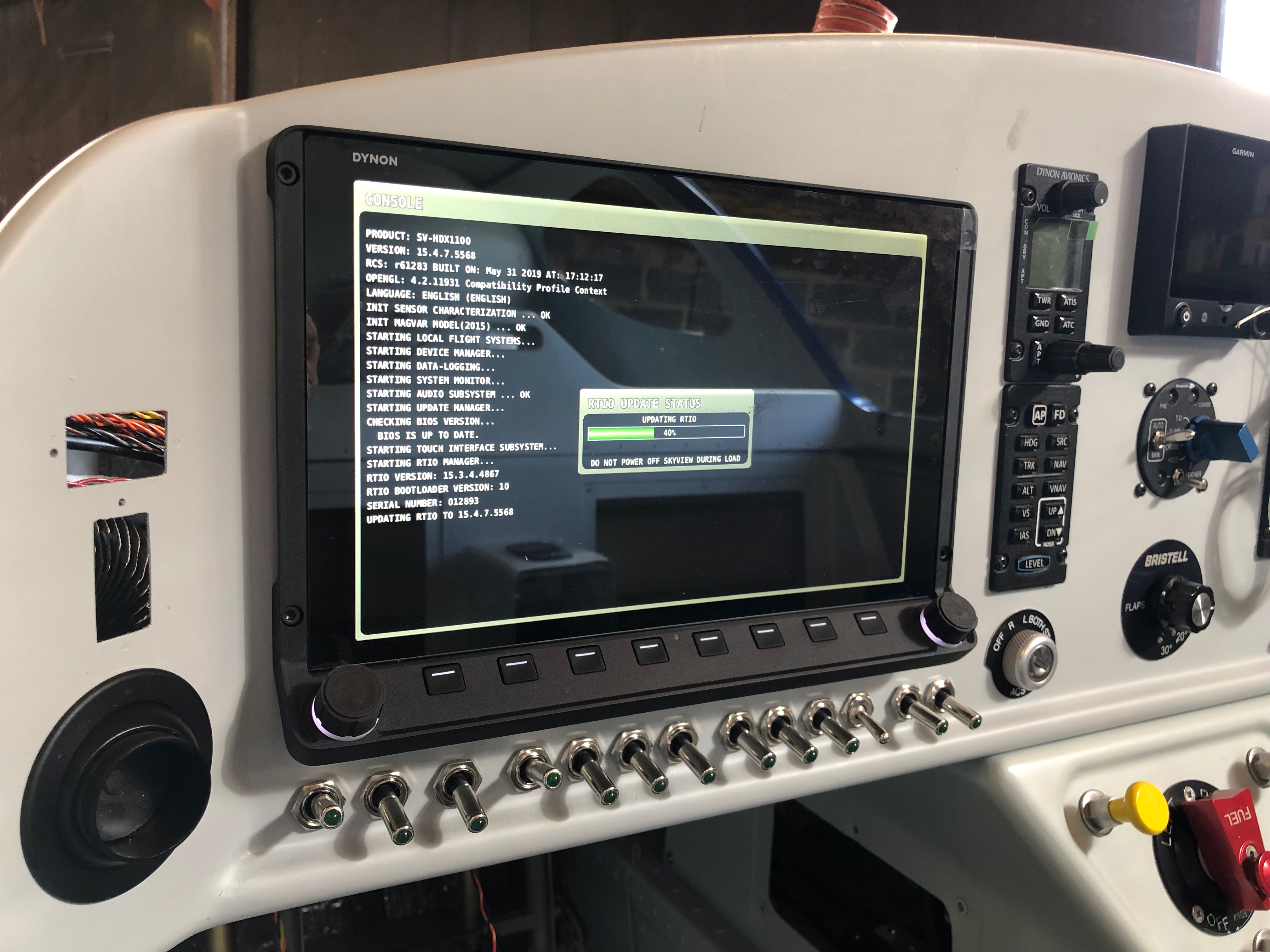
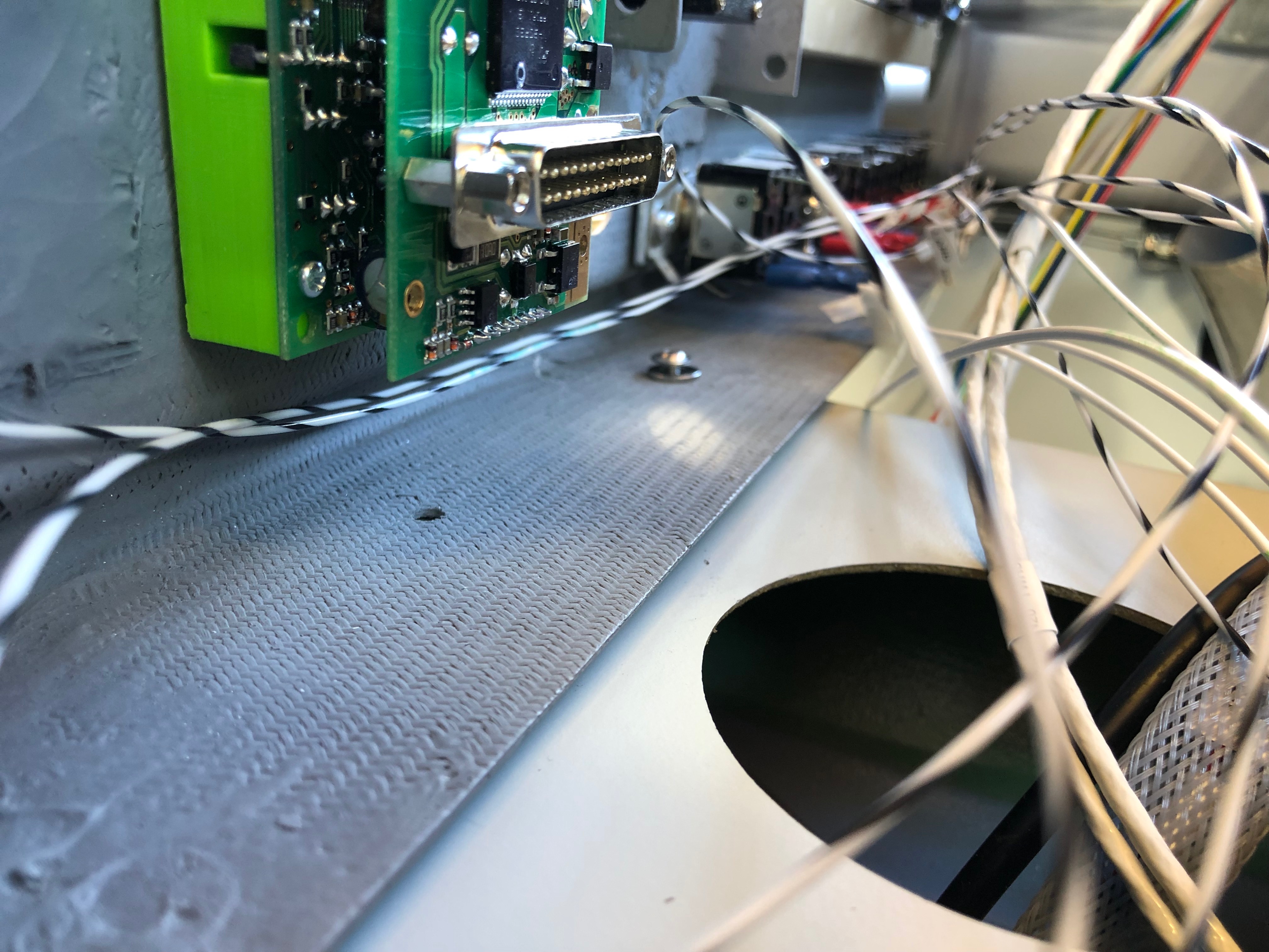
The wiring continues, after each circuit is wired up a check to see if it’s working as expected. All good so far!

As mentioned previously I need to protect the SkyView from a surge from the Amp Shunt so I’ve purchased some 1 amp inline fuses. They are very small…

… and make for a very neat protection solution when positioned inline.
With all the wires ‘under the bonnet’ it’s difficult to make it all tidy…
…but I layout all wire first to see where best to route them before trimming to correct length and terminating. All these will need to be secured too with stand-offs as required.
The servo looms are next. I’ve installed the looms as far as the cockpit and now need to terminate each wire and make up the connector. It requires crimping the pins on each wire with a 4 way crimper.
After crimping they are inserted into the D9 block…
…and the backshell is added. Fairly straightforward but you have to make sure that the crimps are secure. There are two of these, one for roll and one for pitch. Once made up they are plugged onto the SkyView network hub.
Next up is to finish off the engine sensor connections. The correct pinout from the D37 connector is identified and the wire routed as described before trimming to the correct length and terminating. In this case a uninsulated spade connector that slips over the sensor connector. This is the LH CHT sensor…
…and the oil temperature sensor.
A quick check that everything is working. The CHTs, EGTs, Oil Temp, Fuel pressure, Oil pressure, Voltmeter, Ammeter and autopilot have now been completed and work as expected.

Friday 14th June 2019

Music: Take That

I decided to visit Air Expo at Booker yesterday but I can honestly say the show was a complete waste of my time. It was raining all day and a lot of the exhibitors had scaled down their stalls and some hadn’t turned up at all! I did buy a Sky Echo II there so I’ll see how that works when I finally get the plane flying.

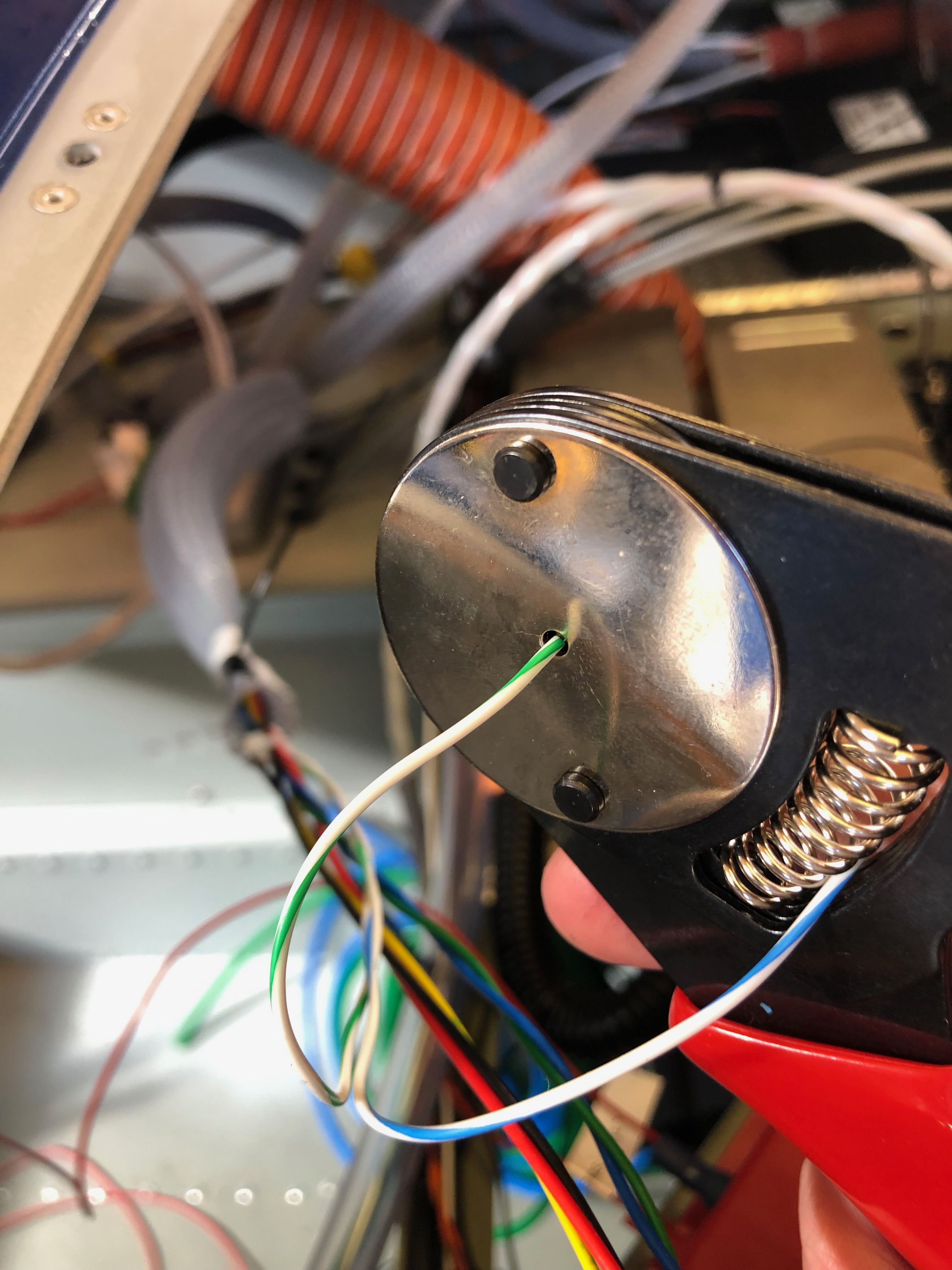
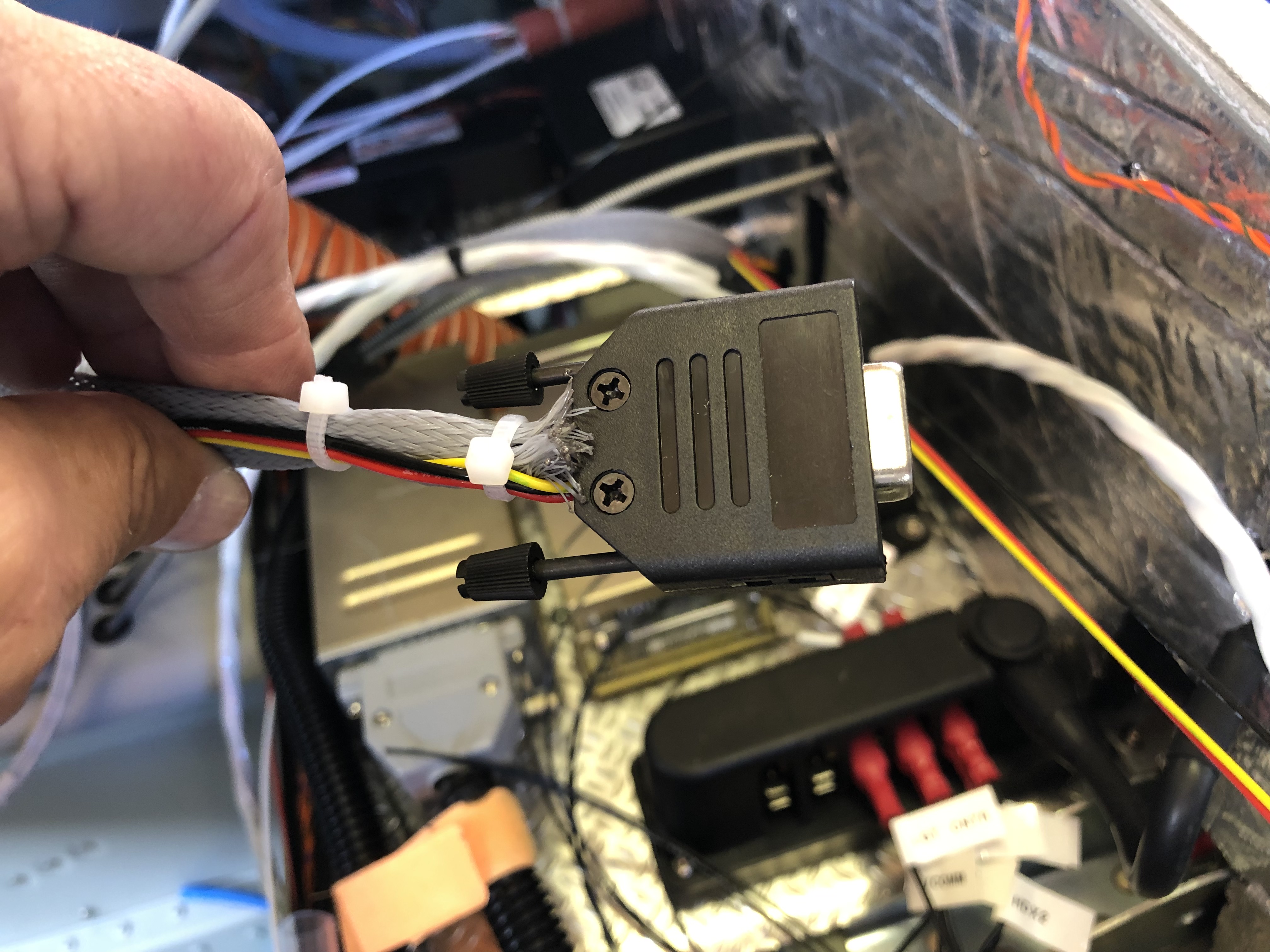
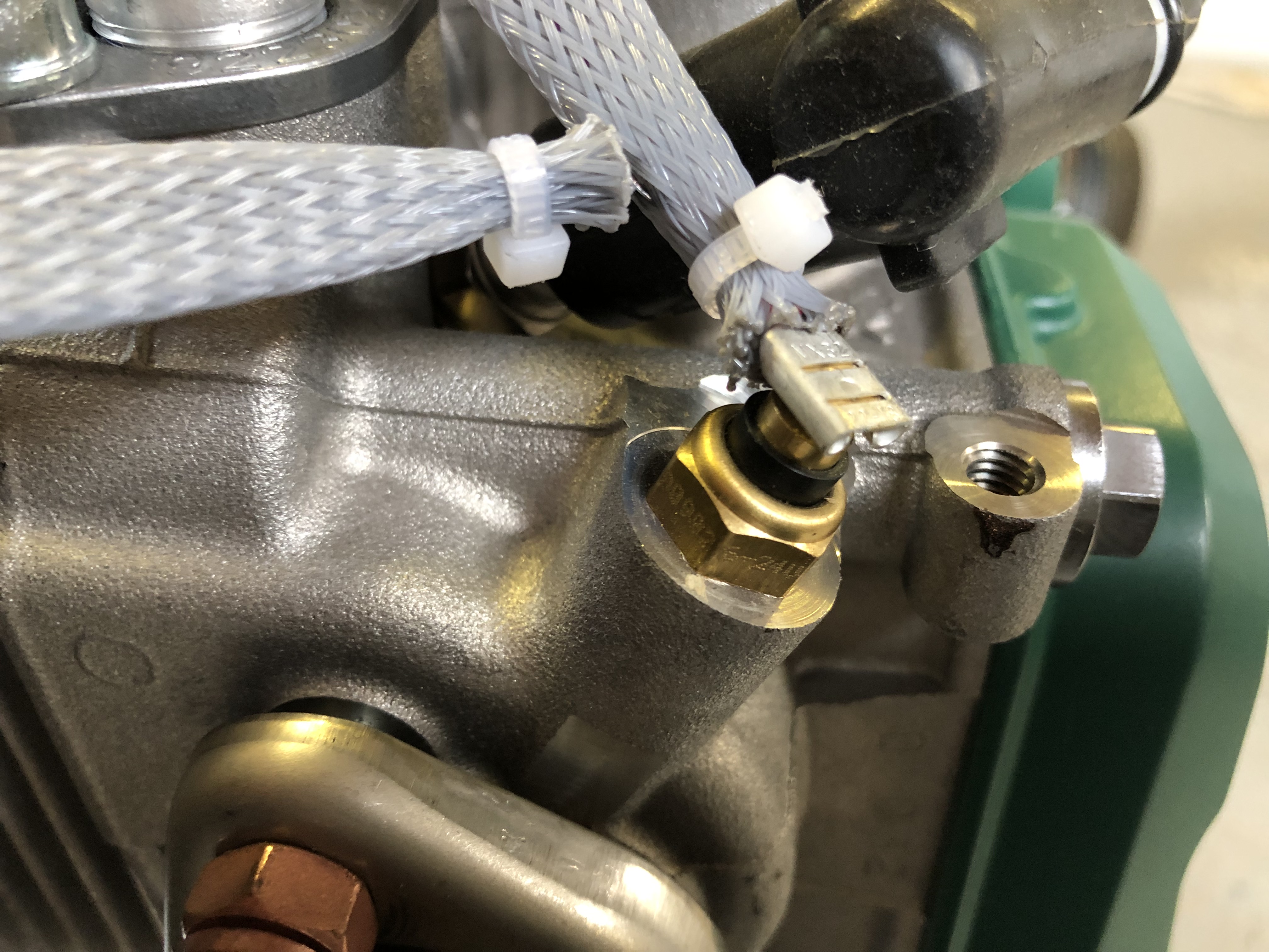
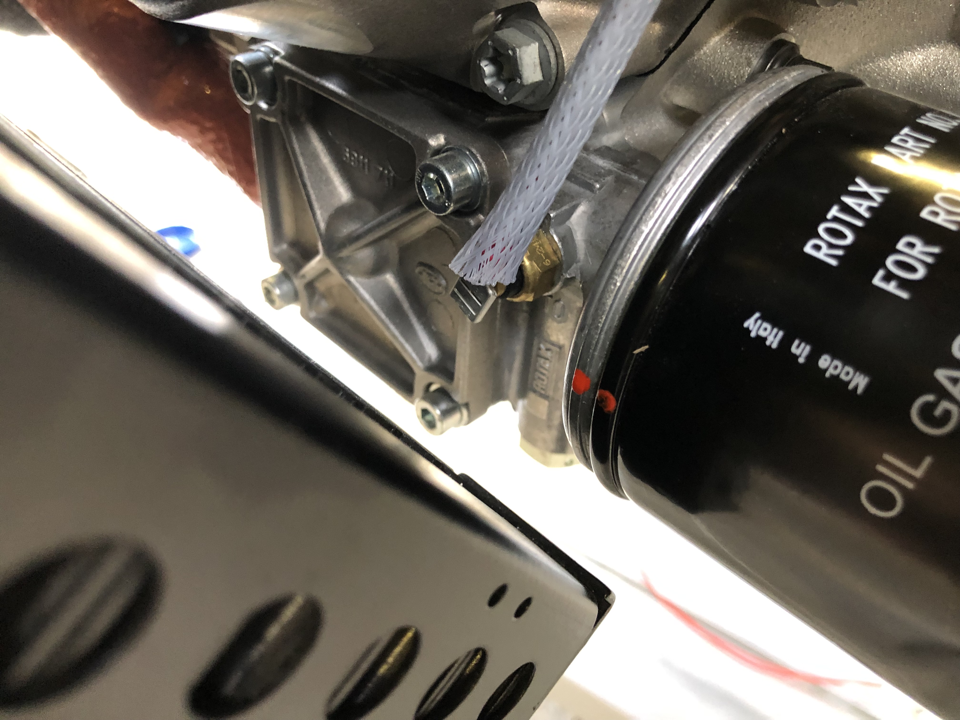
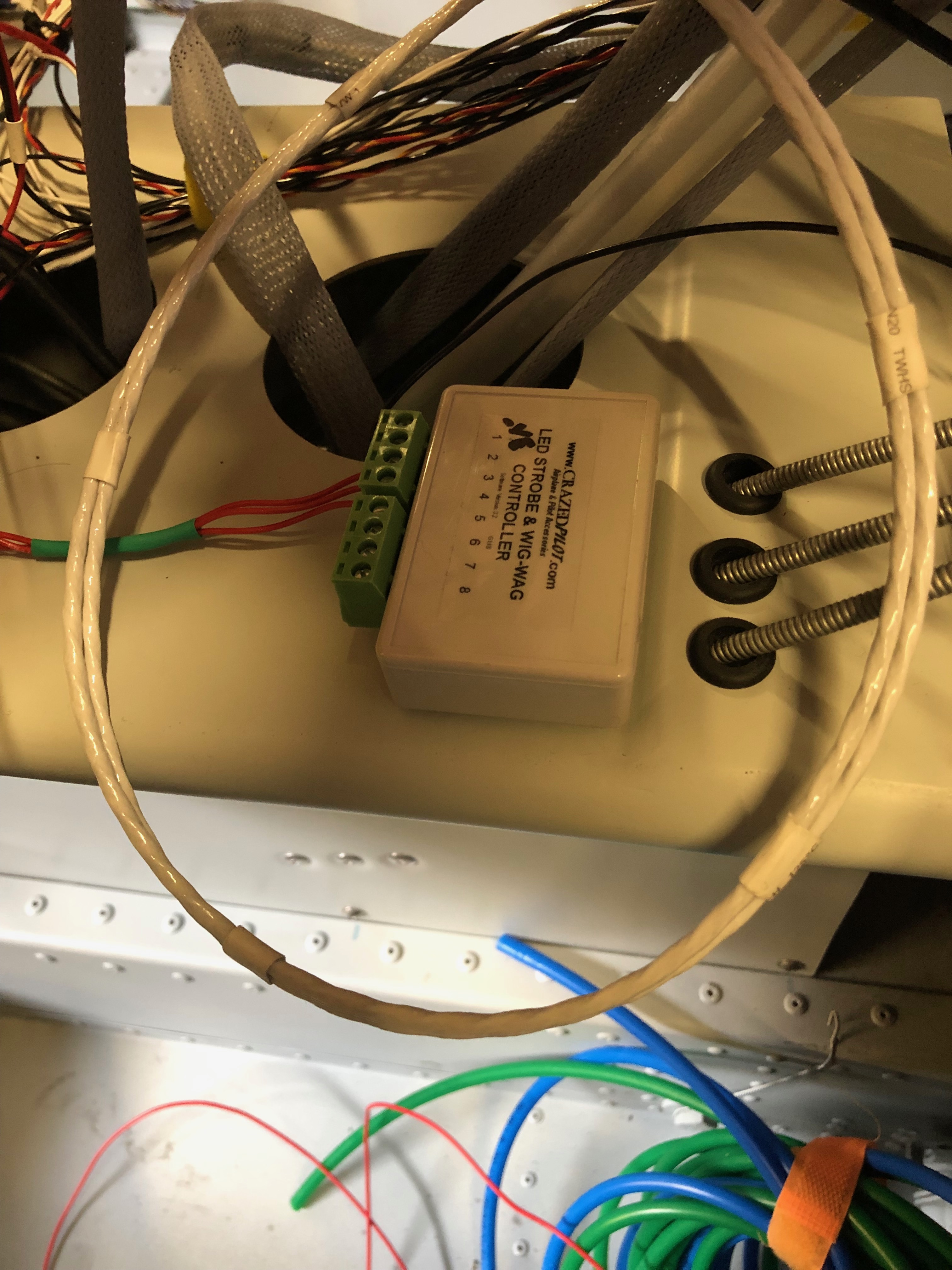
The aim for today was to continue the wiring and connect a few of the sensors.

The EMS loom has a D37 that connects to all the various sensors around the aircraft. It’s good to check the pin out with a multimeter before connecting to any of the sensors.
First up is the MAP sensor. The power and ground on this sensor can be shared with other sensors so I’ve broken out those pins to use for the the fuel pressure sensor.
The system power load can be displayed on the SkyView by measuring the potential difference across a precise resistive load, in this case a Amp shunt. The wires connect to either side of the resister. To protect the SkyView from high currents a 1 amp fuse is connected inline which I’ve ordered and will be arriving Sunday so I’ll fit on Monday.
The landing light controller that I bought from the States is wired up to a 3 position switch. I’ve designed the lights to be steady, wig wag and strobe. Hopefully it’ll work as designed.
To get the light functions I need a 3 pole and 2 pole switch.
The fuel pressure sensor is next but will be done on Monday now as I’ve run out of time.
The HDX displaying in s ‘6 pack’ mode but you can see some of the sensors working correctly including the MAP, voltmeter and ammeter readings.

Wednesday 12th June 2019

Music: Ed Sheeran and Turin Brakes

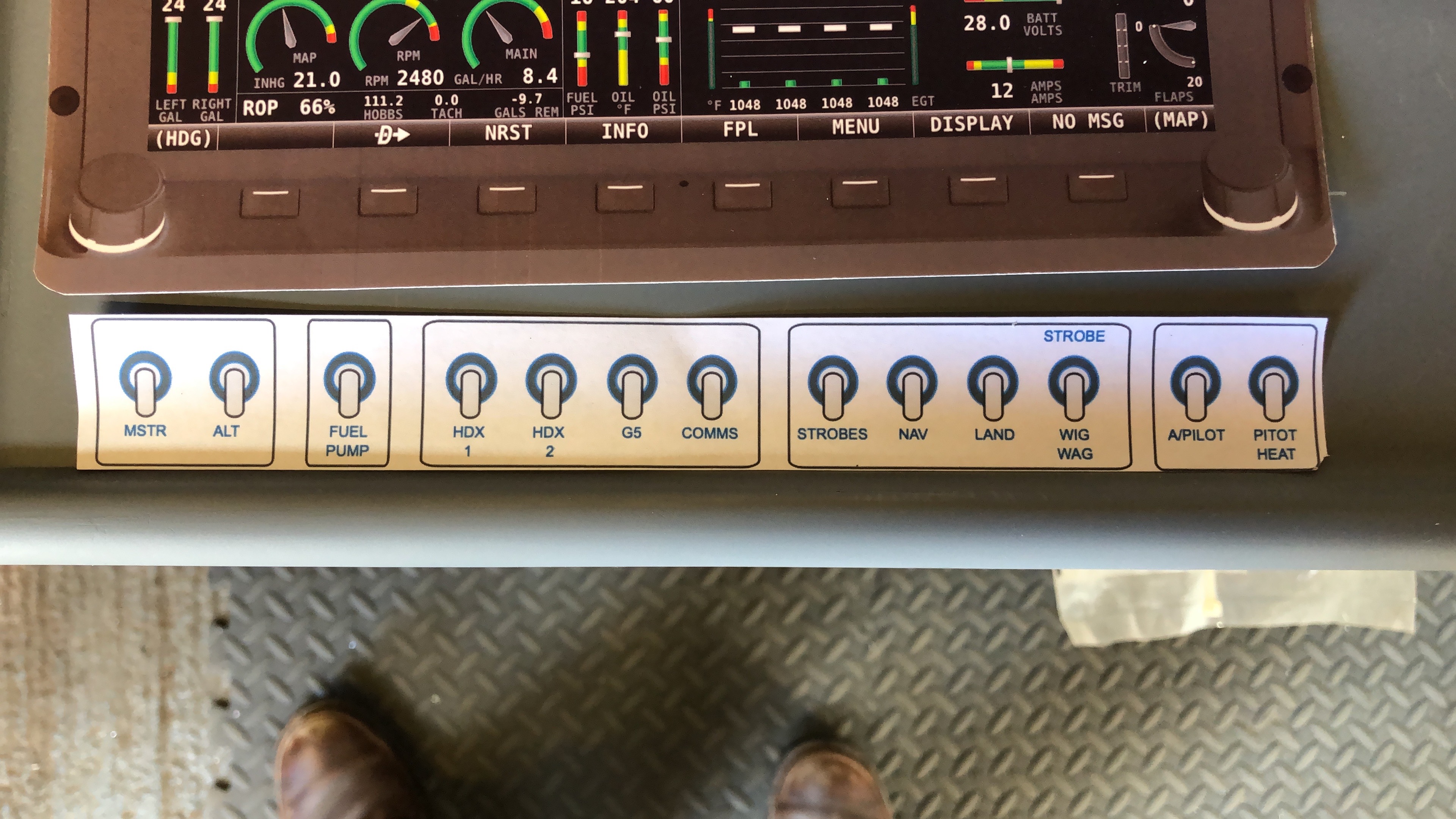
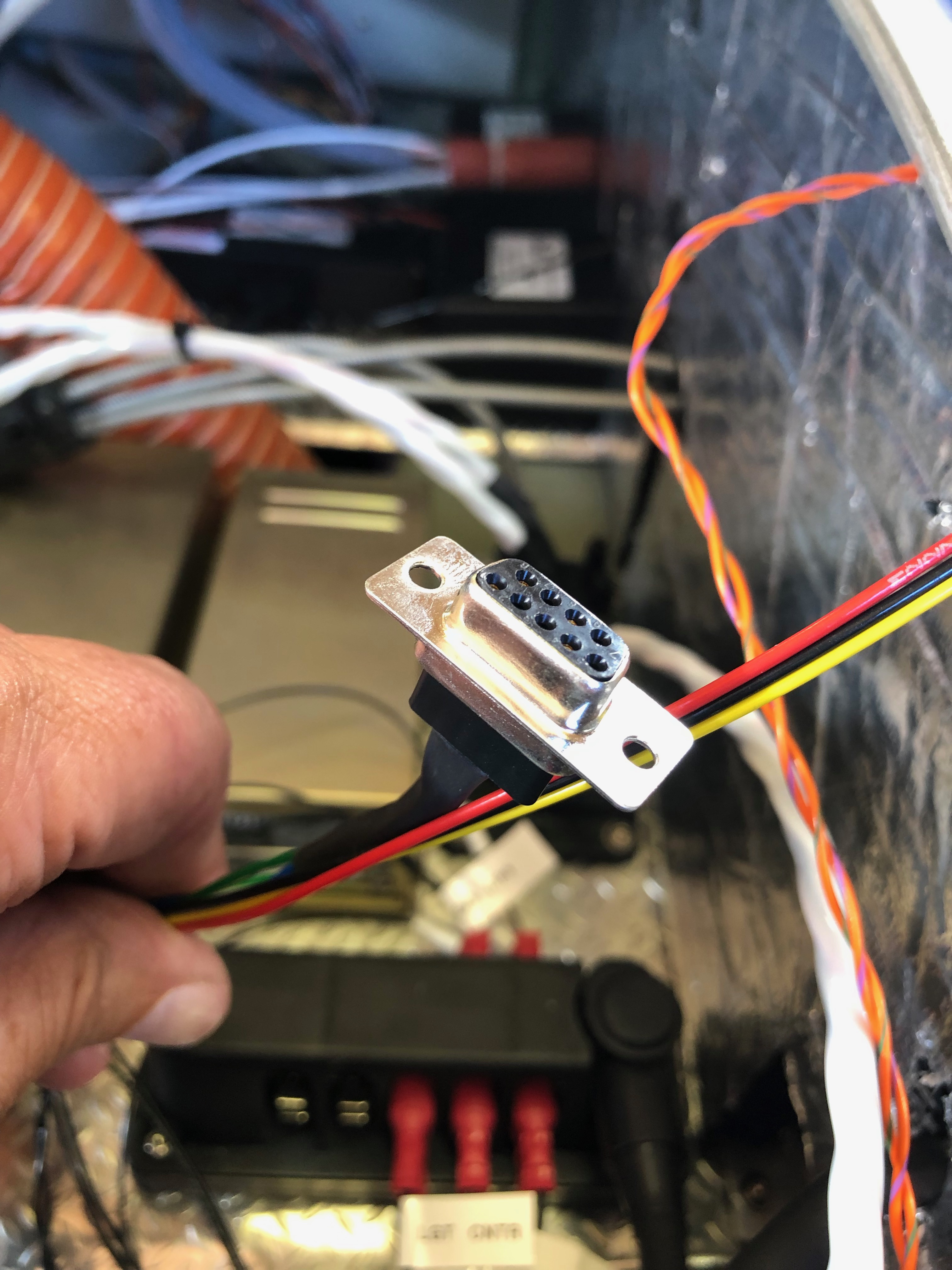
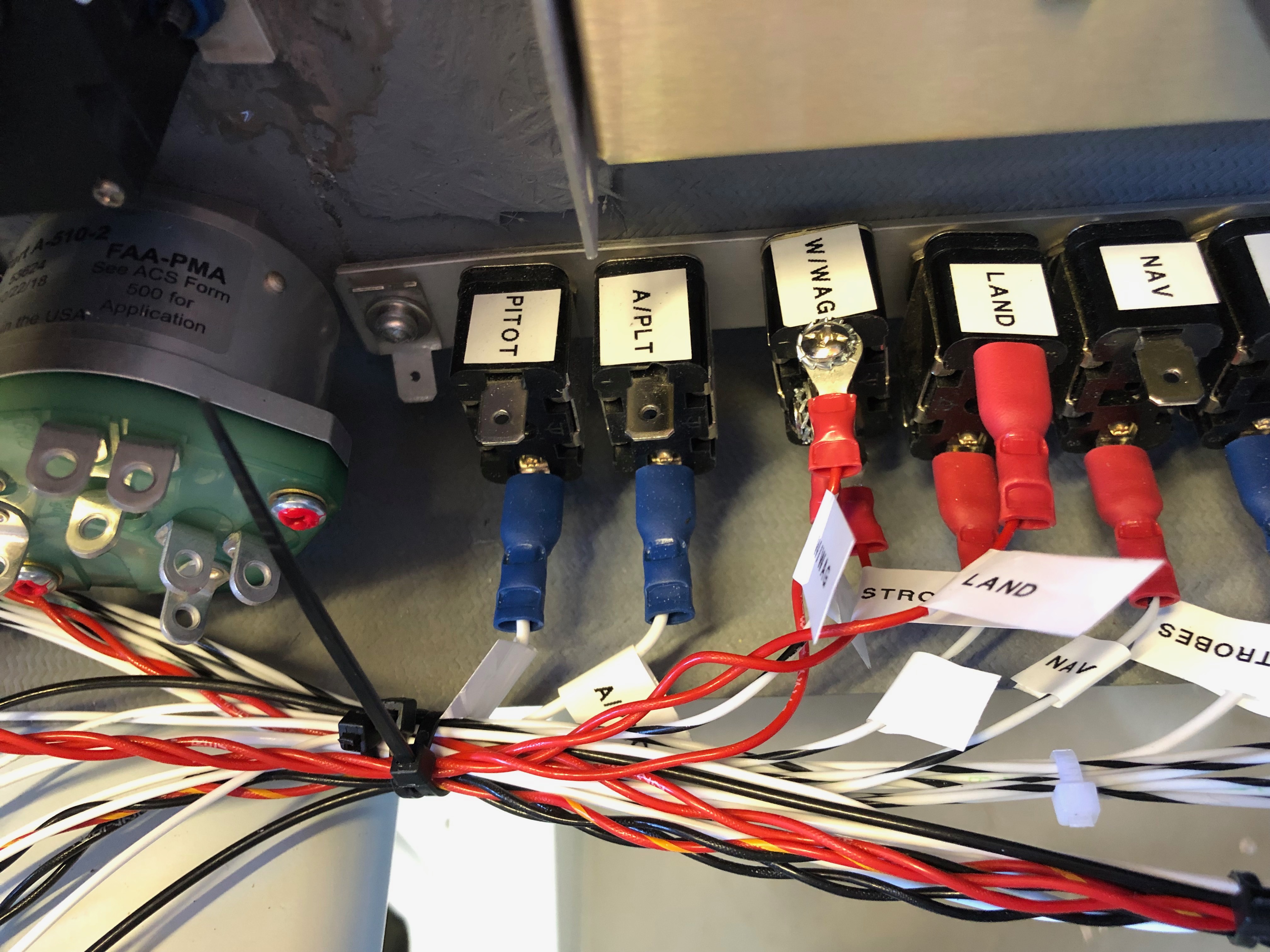
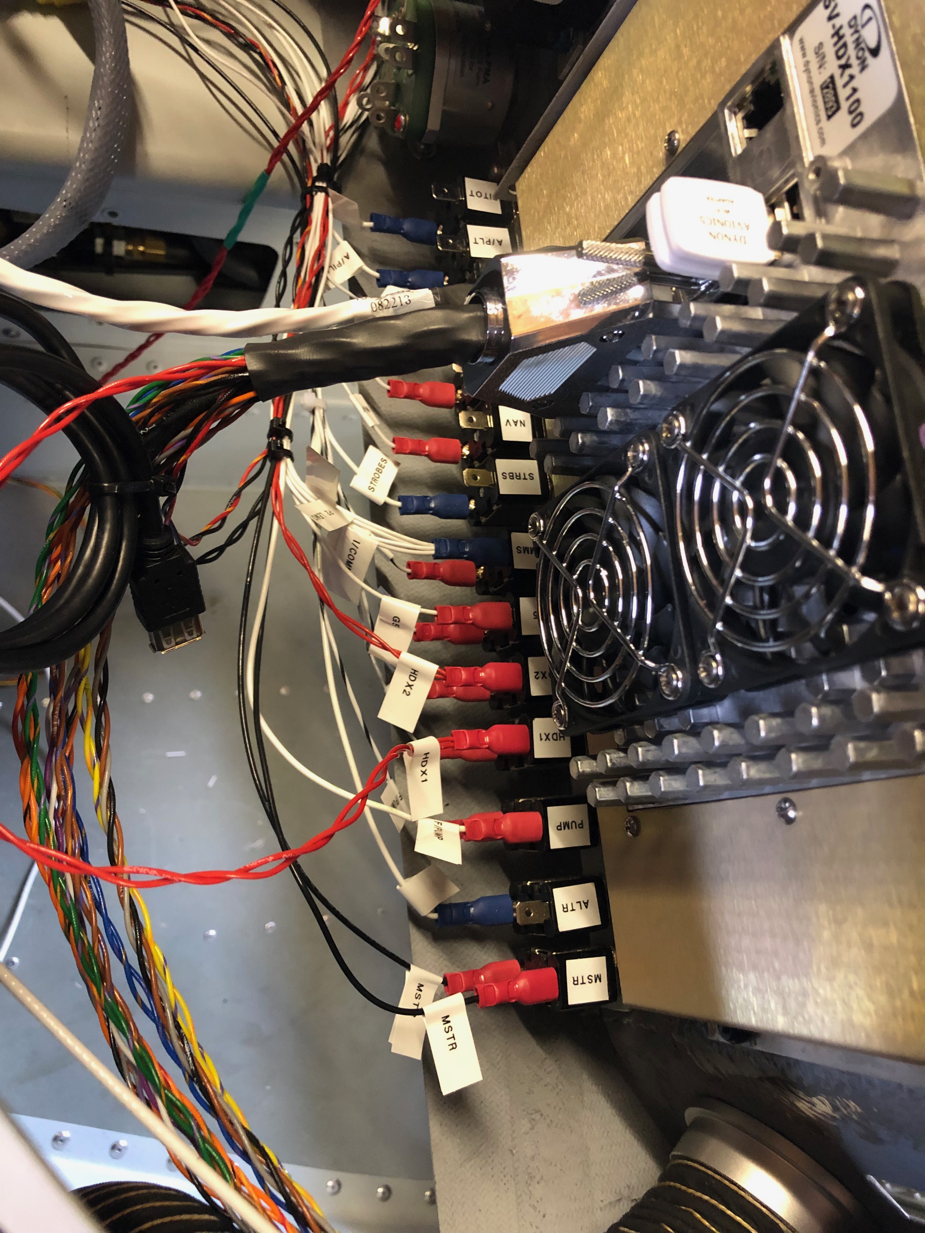
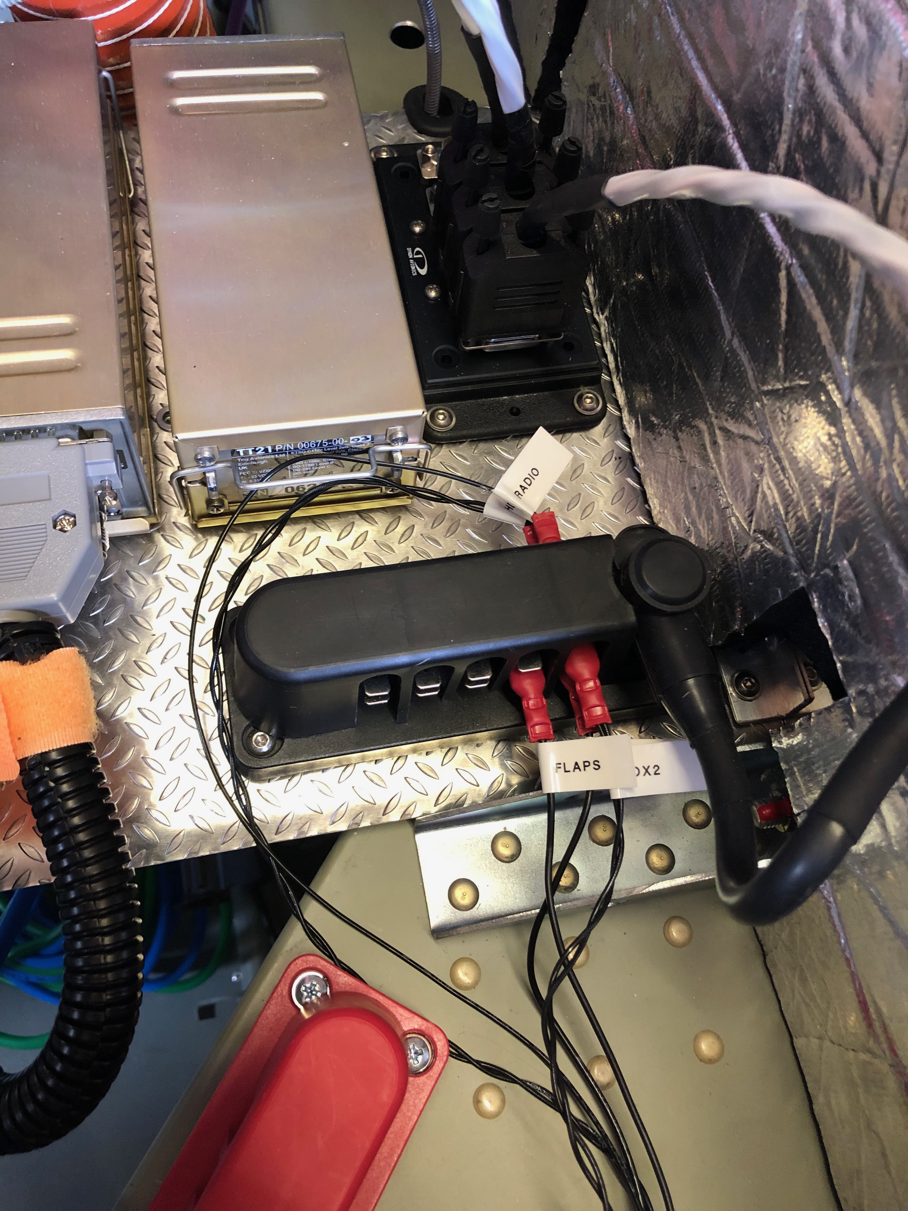
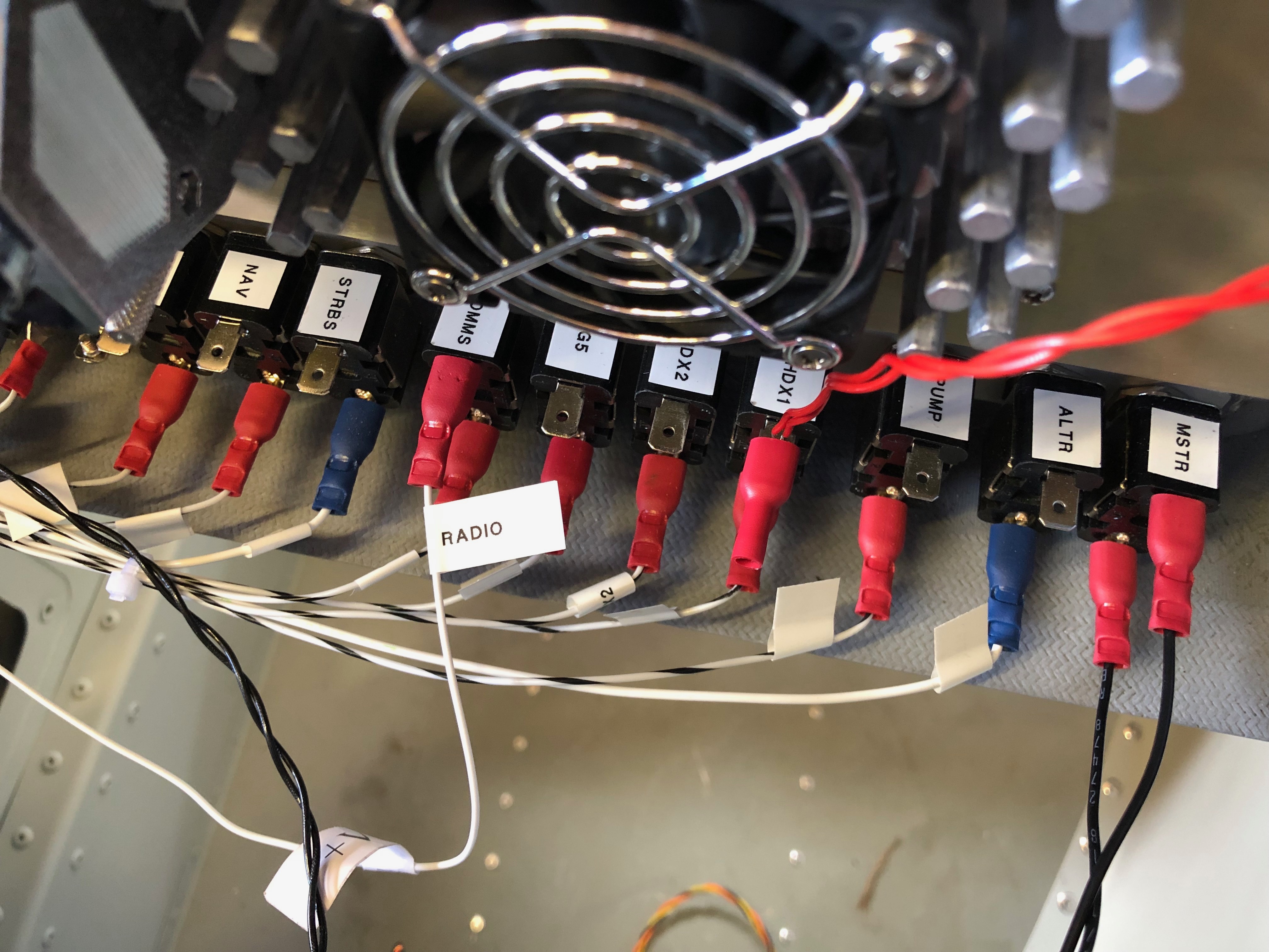
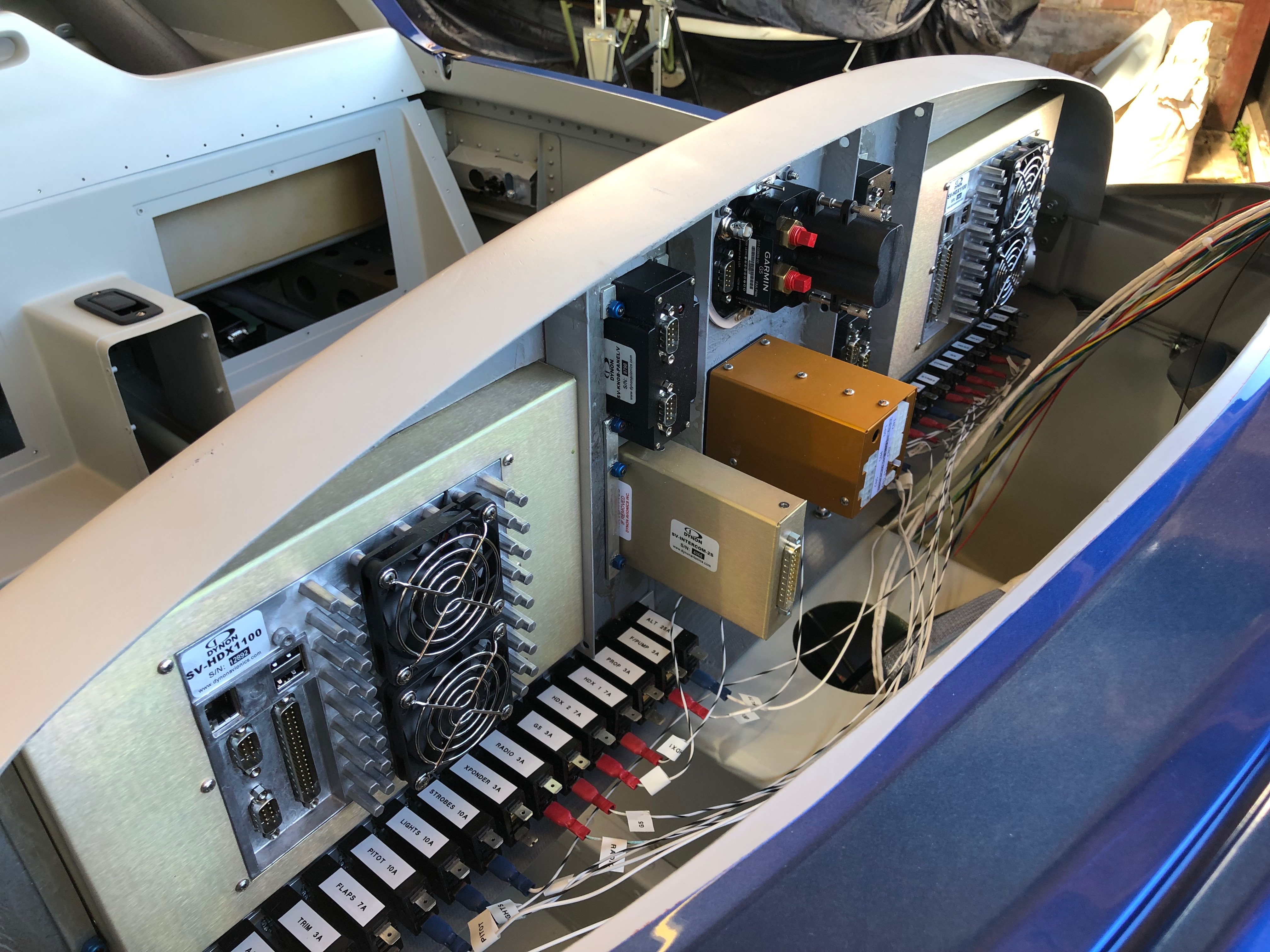
Work continues on the wiring today (and no doubt for a few days more but got quite a lot done today having completed the Master, Fuel Pump, HDX 1, & 2, G5 and Radio circuits.

This is the loom for just one of the SkyView HDX screens. It looks intimidating on first looks but they all do something and you just have to work out where they go!
The difficult bit was designing the electrical circuit to power all the devices. As I’d fitted the circuit breakers and switches and fitted the interconnecting wires it makes it quite easy to complete the circuit.
It’s getting quite busy…
so I’m starting to arrange the wire bundles in an orderly fashion as planned.
This is the Wig / Wag controller that I bought from the states to give better visibility whilst flying. It allows the landing lights to be steady, flash alternately or flash like a strobe. Just hope it works as promoted!

Tuesday 11th June 2019

Music: Röyksopp and Dido

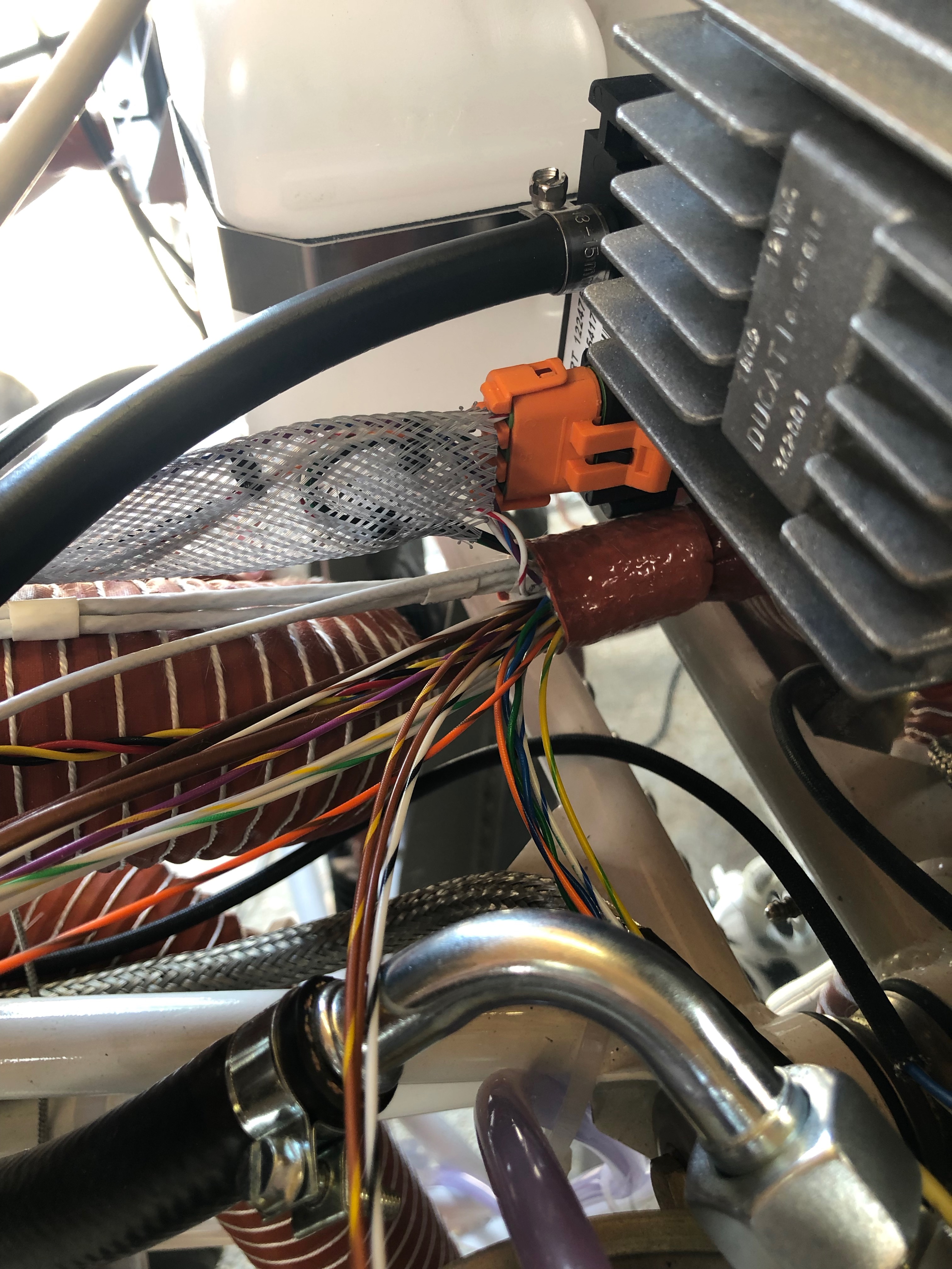
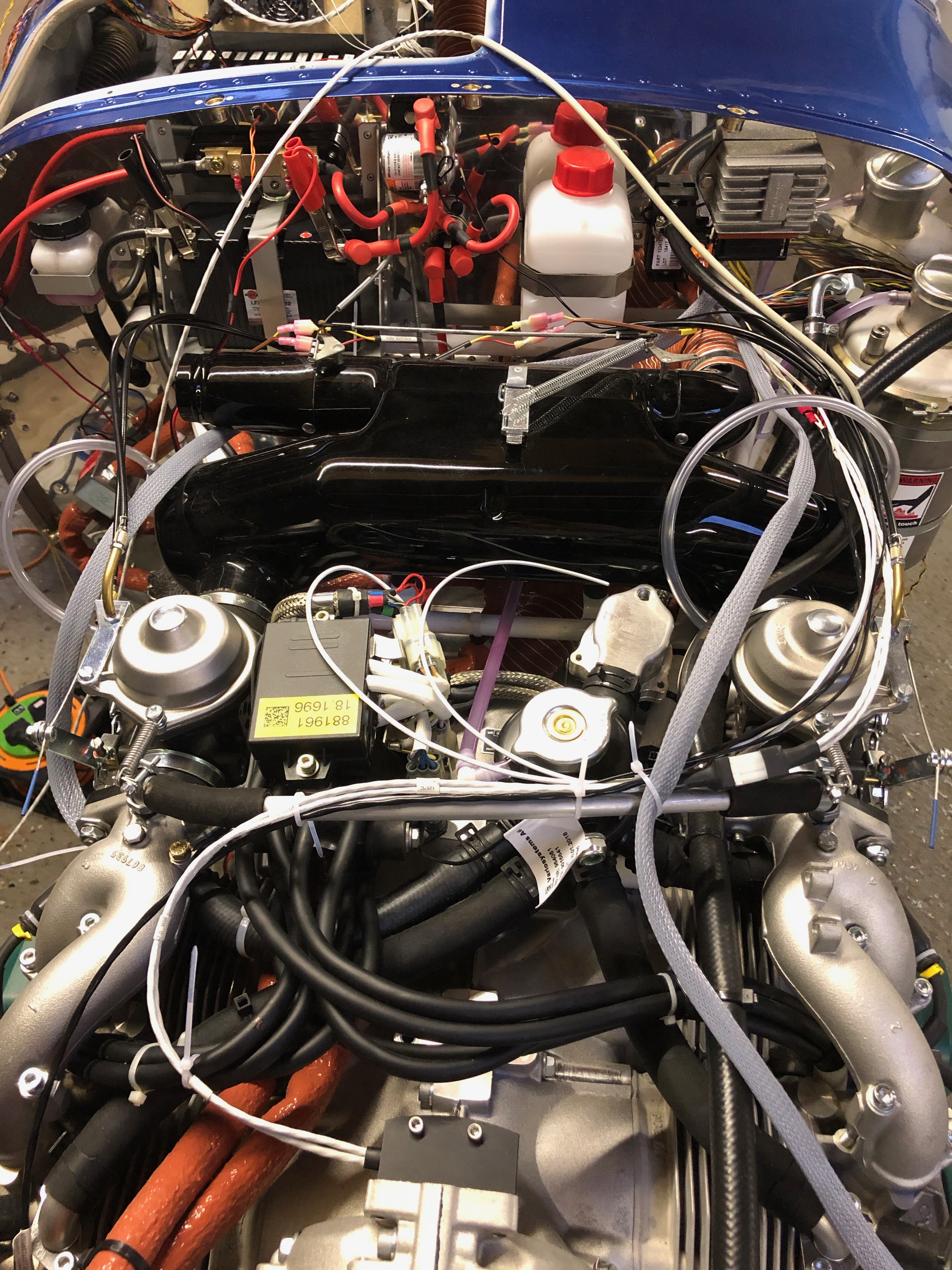
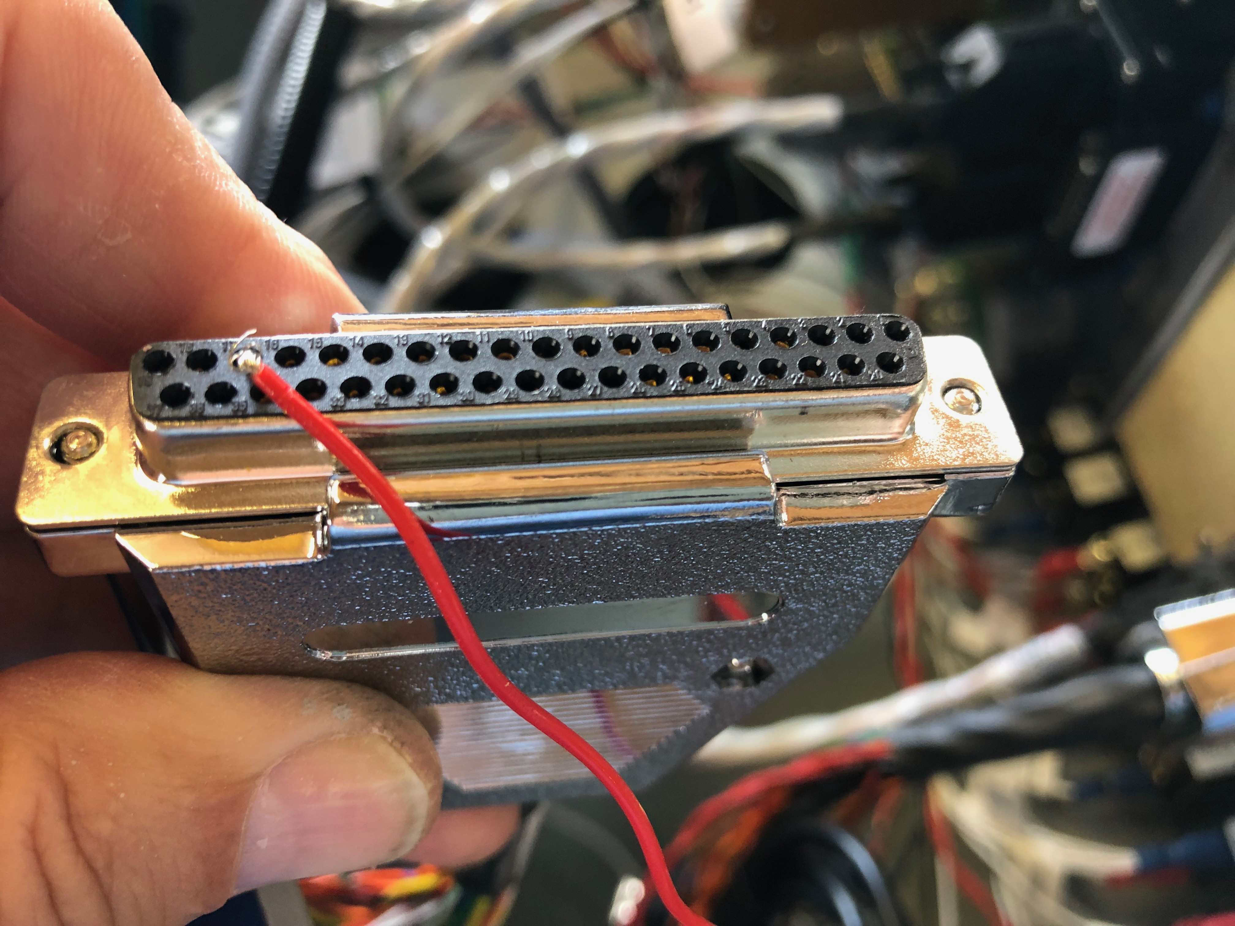
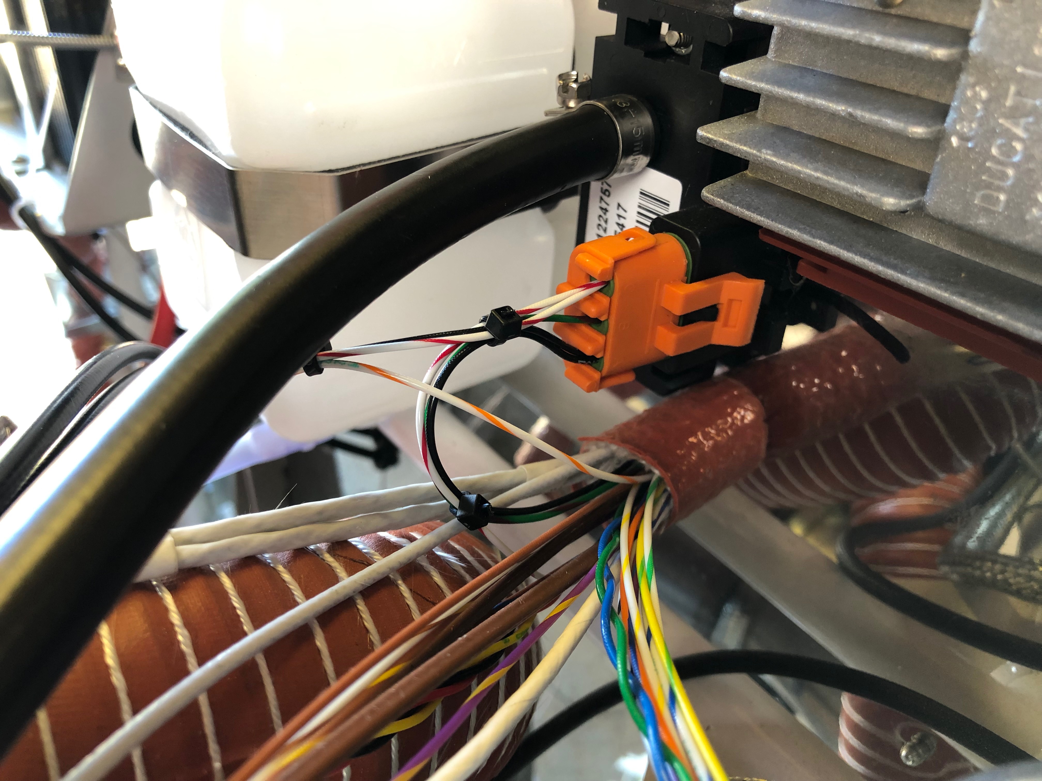
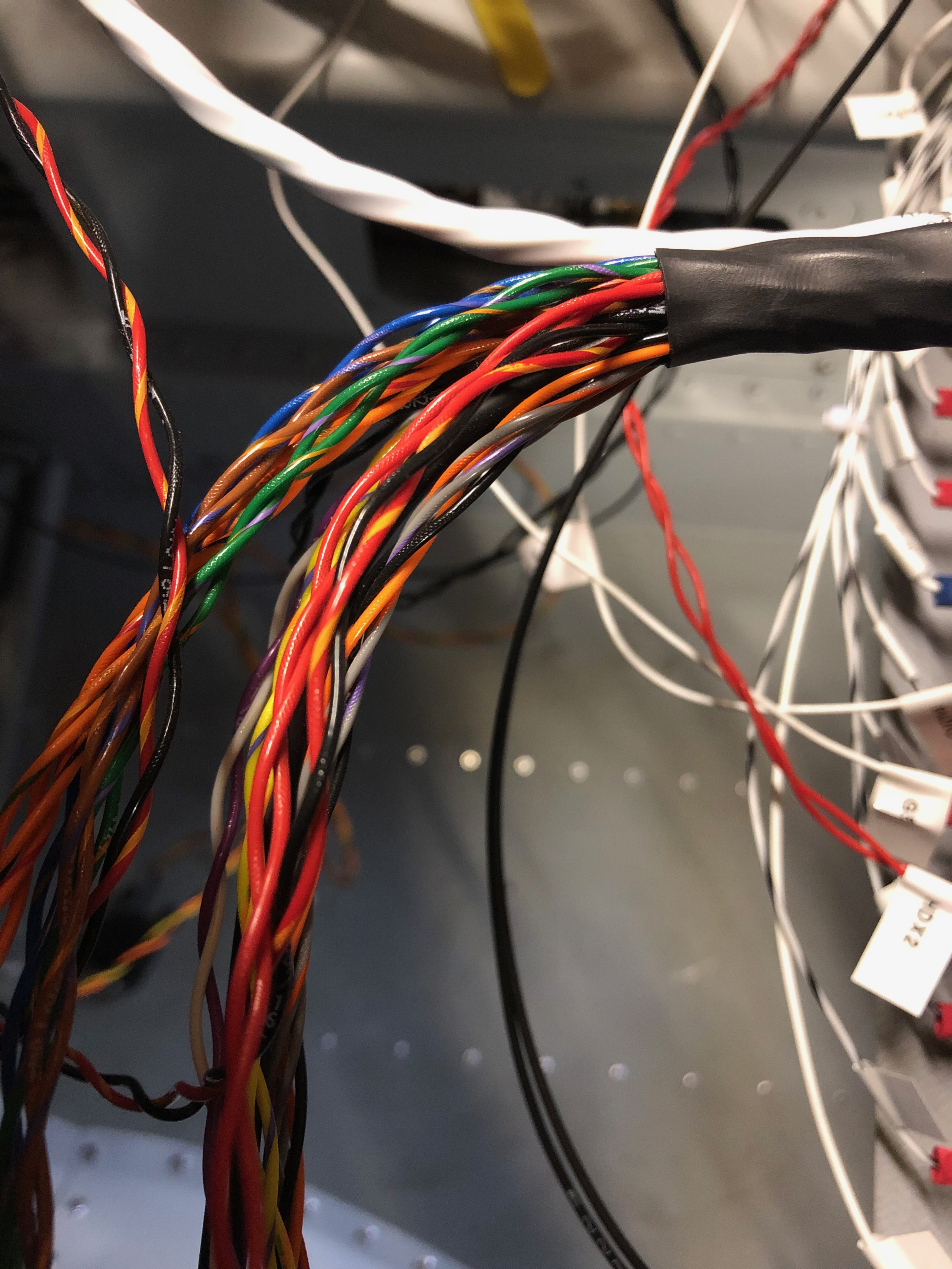
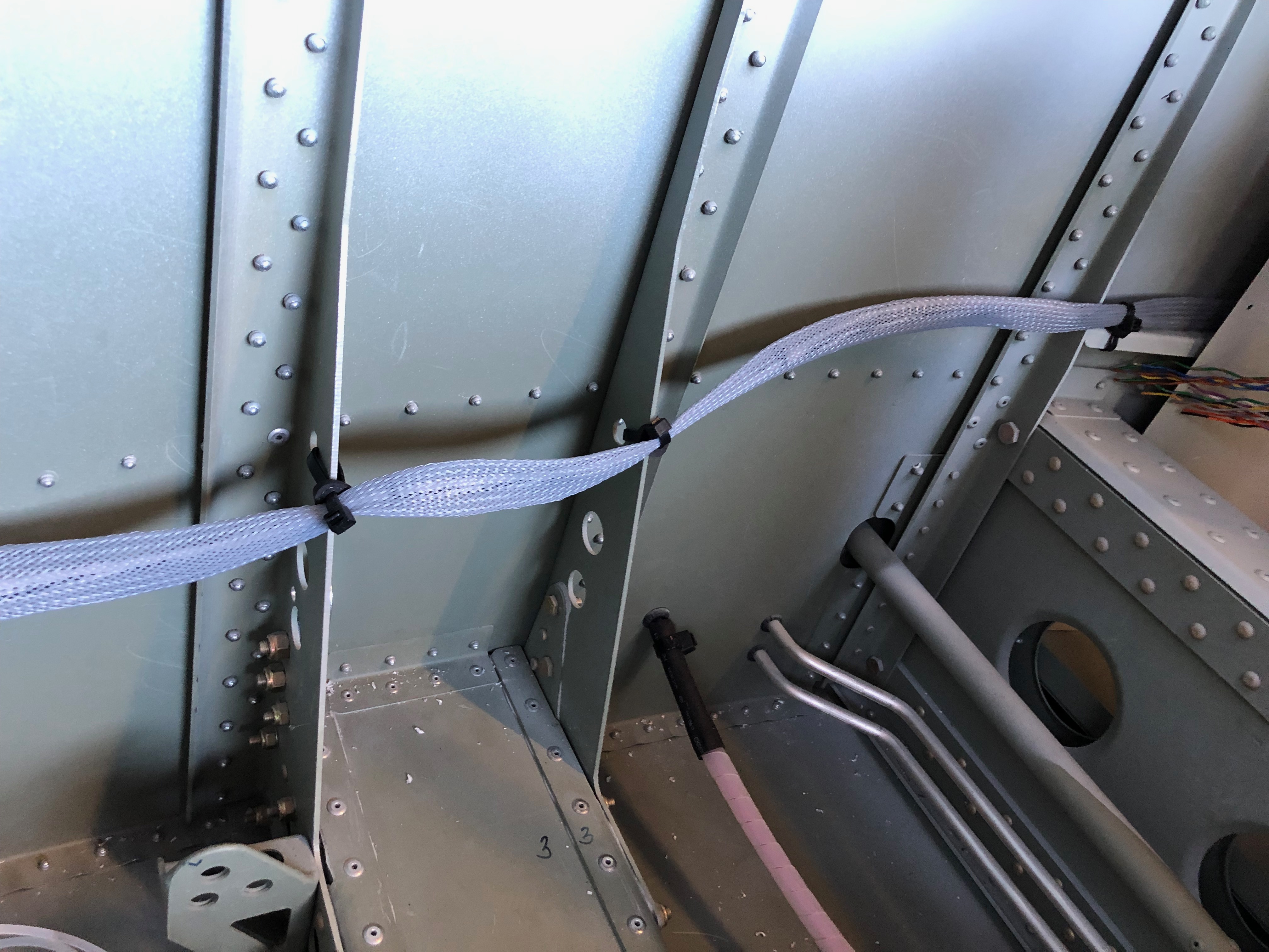
It’s time to do the wiring. This is going to be long job as there are wires all over the place! There are some things that must be done to make sure that it’s maintainable in the future like labelling as it’s easy to lose track of where wires are going from and to and obviously it’s got to look neat and tidy. First thing is to look at suitable routings for the bundles and make sure they make ‘sense’ then start laying them out. This is one of those jobs that you just have to keep going at and eventually it’s finished!

First up is to protect from reverse currents when the master switch is turned off. This is accomplished by placing a diode across the positive and negative posts on the battery contacter.
It looks a quite simple but it gets the job done.
One of the easy jobs is to run all the ‘earths’ back to the earthing block. After terminating each wire with a insulated female connector a label is attached to the lead. These are just printed off a electronic dymo babbling machine and seem to be suitable for the job.
Once the earth is connected, a quick check of the circuit logic and then I can temporarily power up the circuit.
Whilst the screen is powered up on main power I thought I’d update the system software to the latest version. The software has a boot loader that updates all the other attached devices like the autopilot and knob panel.
Last job today was to run the G5 to GMU11 loom in and secure in place.

Monday 10th June 2019

Music: Star Sailor and Turin Brakes

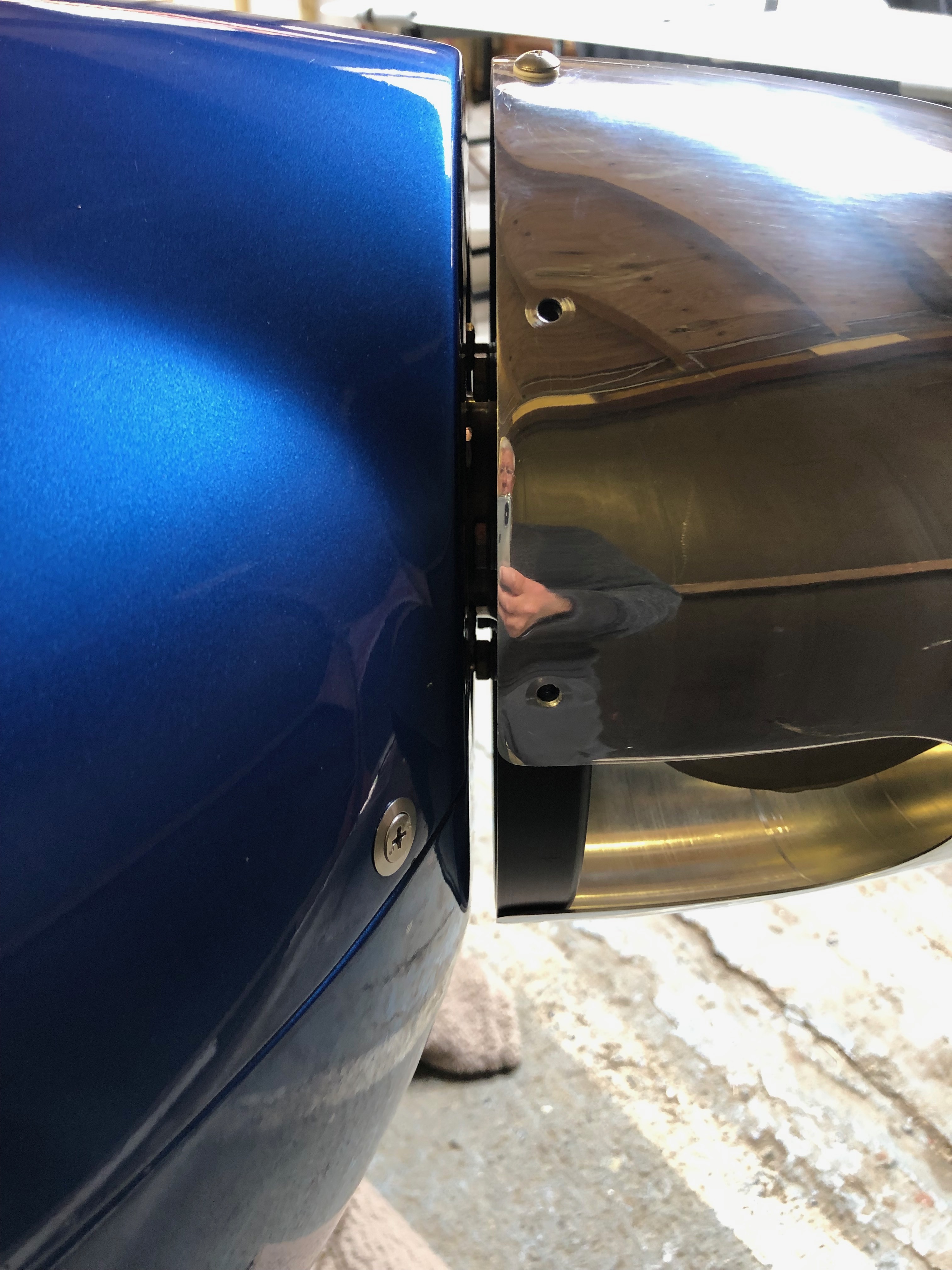
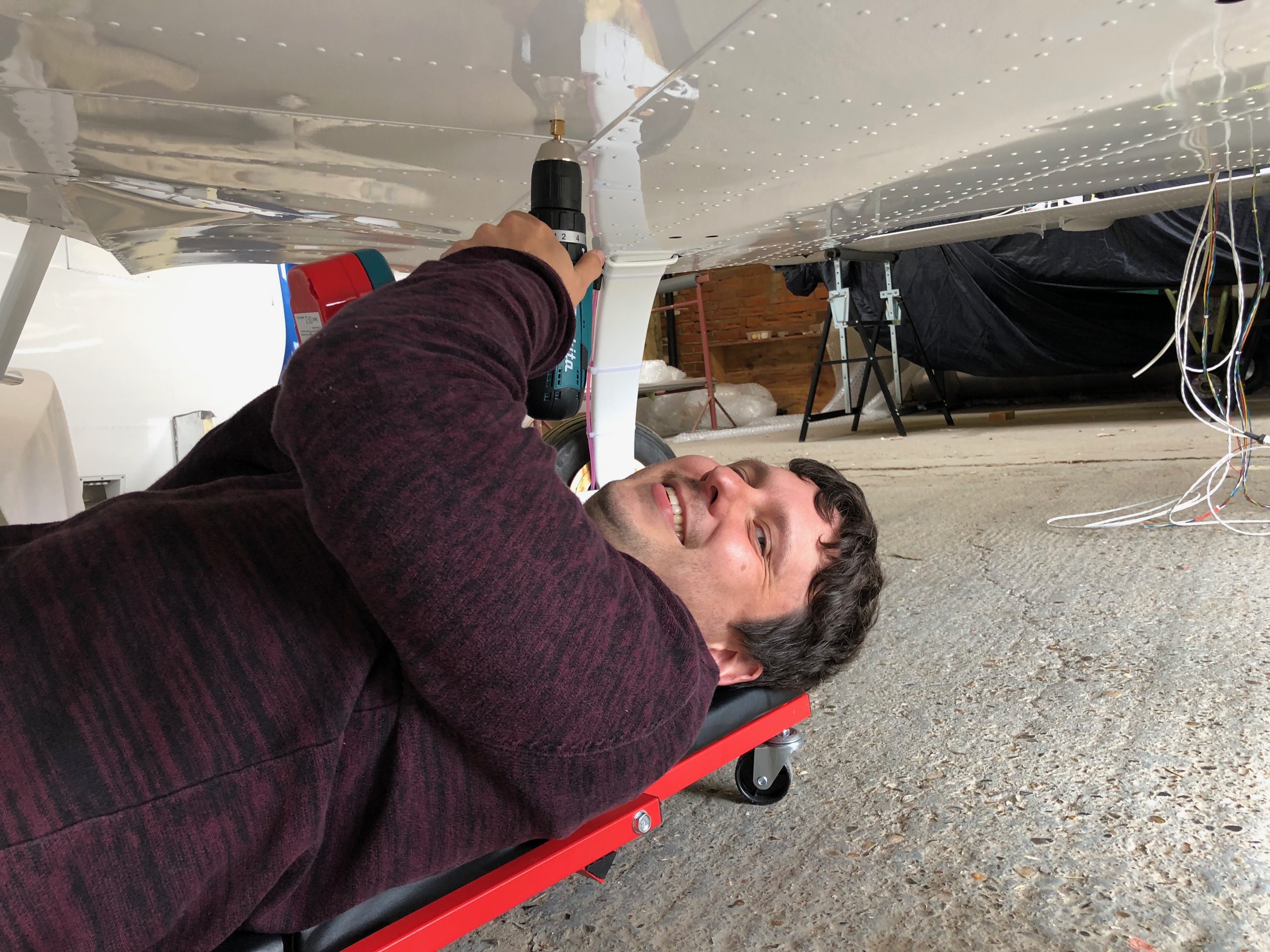
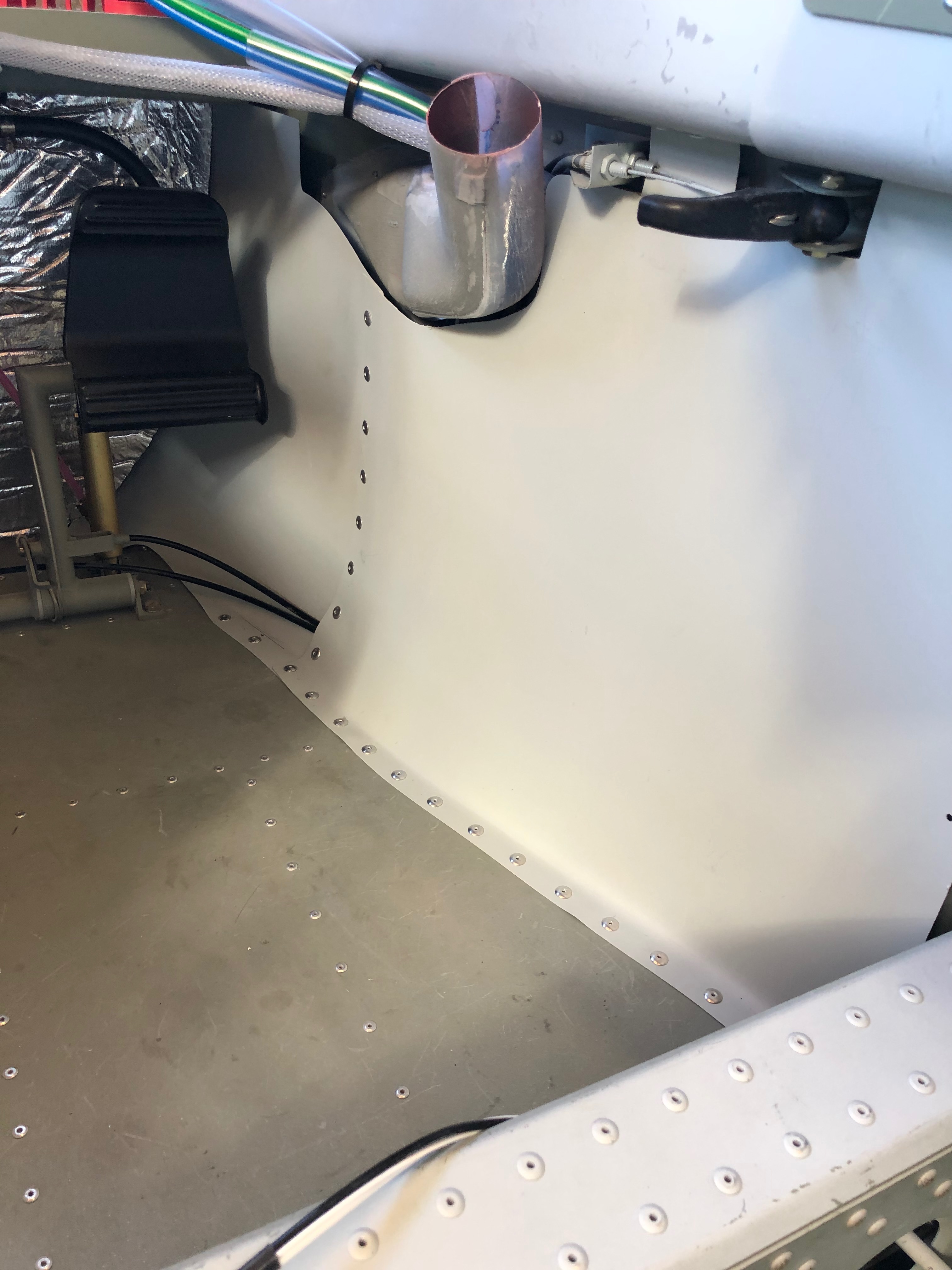
Dave came down to spend a day with me to see how the build is going so far and help me with fitting the prop hub and transponder aerial.

Forgot to attach the panel air vent ducting before I installed the panel. It’s a lot more fiddly i can tell you!
Now I’ve received the drive lugs I ordered from CFS Aero I can attach the prop extension to the drive plate. The bolts to attach the extension to the drive plate are 8mm and the bolts to attache the prop back plate are AN5. So metric and imperial in the same installation – how ridiculous!
The drive lugs are press fit and have a slight taper so the bolts are used to draw the lugs into the drive plate.
The bolts have been lightly tightened before torquing up to 24NM.
The mini slip ring control wires are adjusted so they hang just out the of the front of the prop extension.
Heat shrink tubing is added to each wire and the hub offered up to allow the control wires to be connected.
A heat gun is used to heat the heat shrink and the wires are pushed into the hollow shaft.
Some Duralac is added to the lugs that enter the hub to ease disassembly and the bolts tightened.
Time to check that I’ve got the measurements right for the prop extension so the engine cowlings are fixed in place.
A good fit with an acceptable gap, so shouldn’t rub in service. I’ll fit the blades closer to finishing the plane to save them getting damaged.
Next up is to install the transponder aerial. I’ve decided to mount it centrally between the main wheels. Still have to make up the coax for the radio and transponder but going to Air Expo on Thursday so will look to pick it up there.
Dave checking out the pilots seat before leaving for home.
So most of the main work has been completed so it’s time to start on the wiring. Not sure how long it’s going to take but need to make a tidy job of it and make sure that it’s easy to trace and maintain in the future.

Thursday 6th June 2019

Music: Dido, Easy 90’s

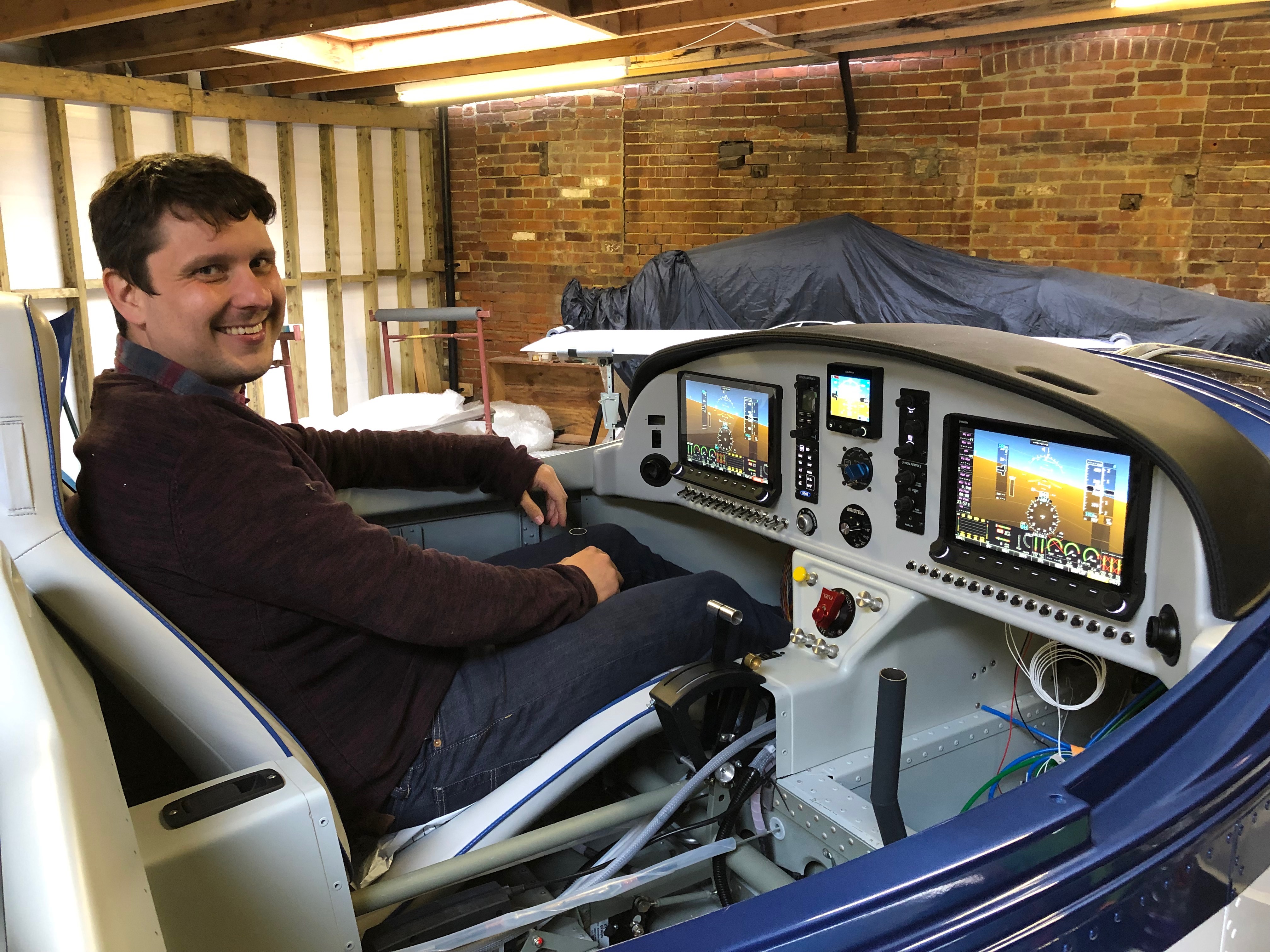
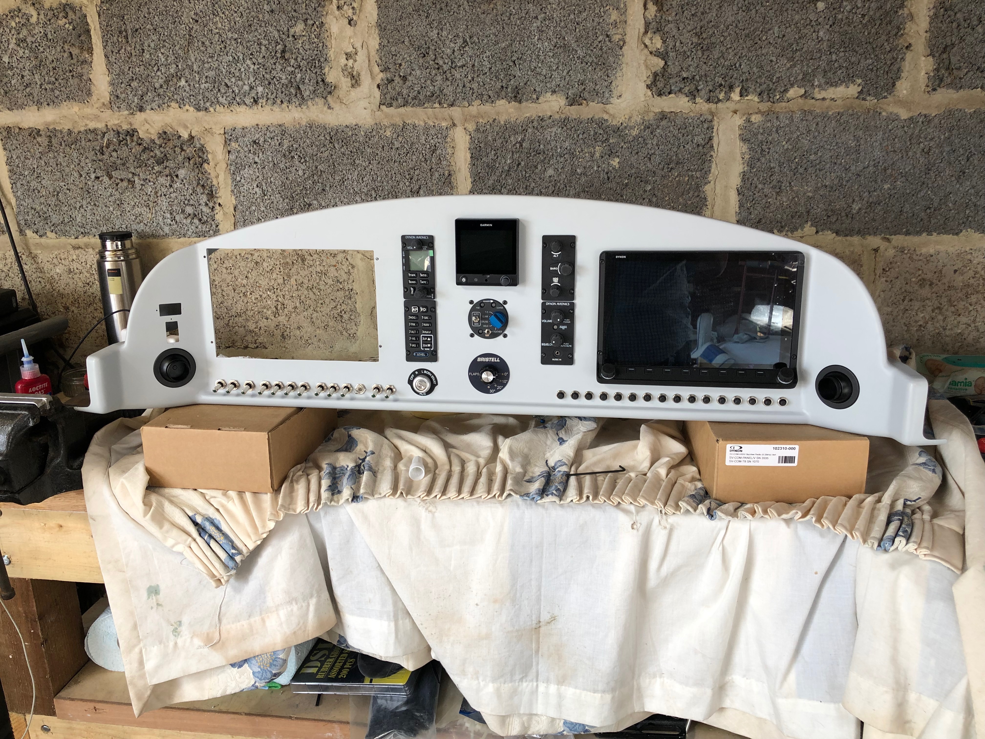
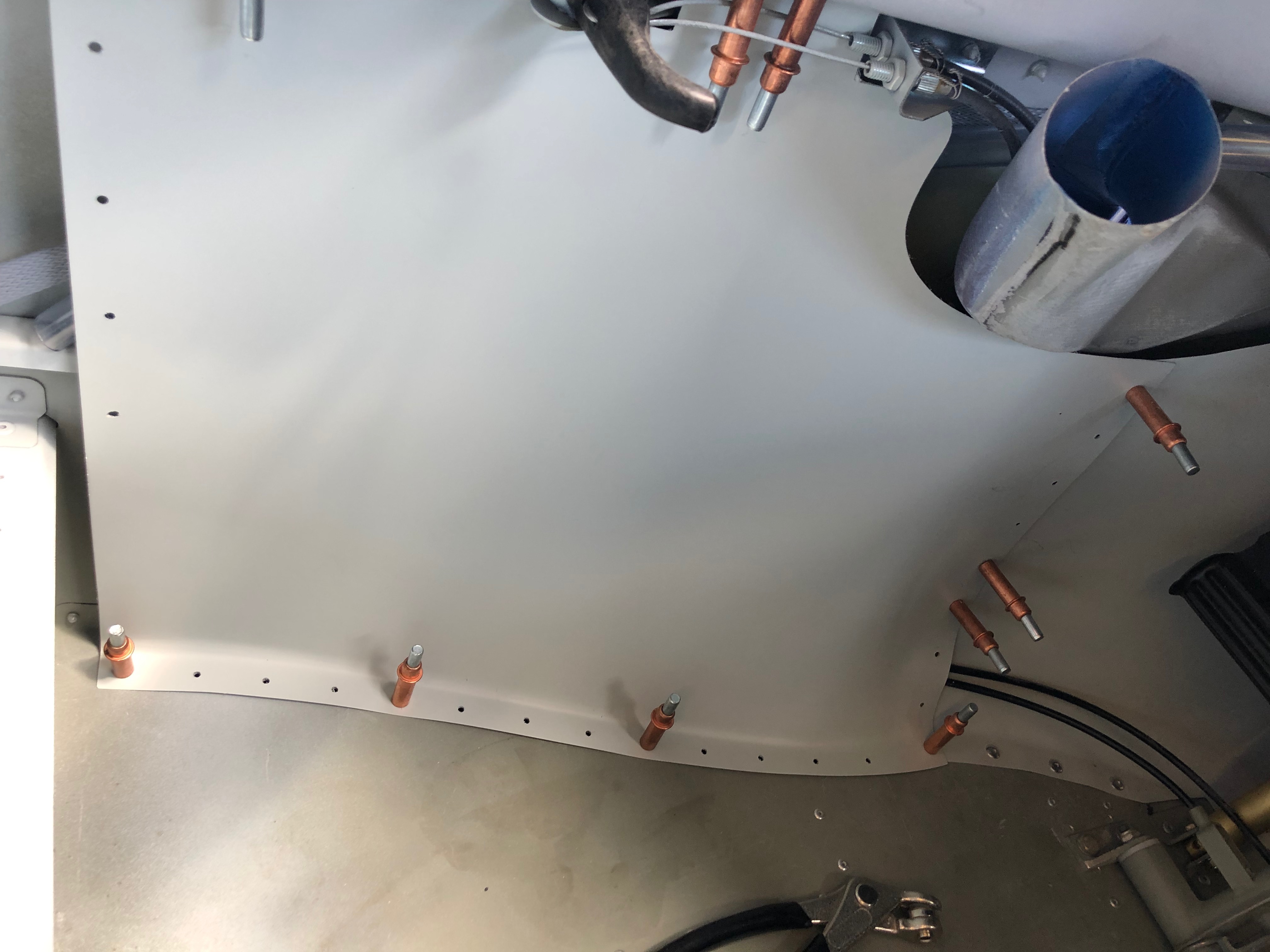
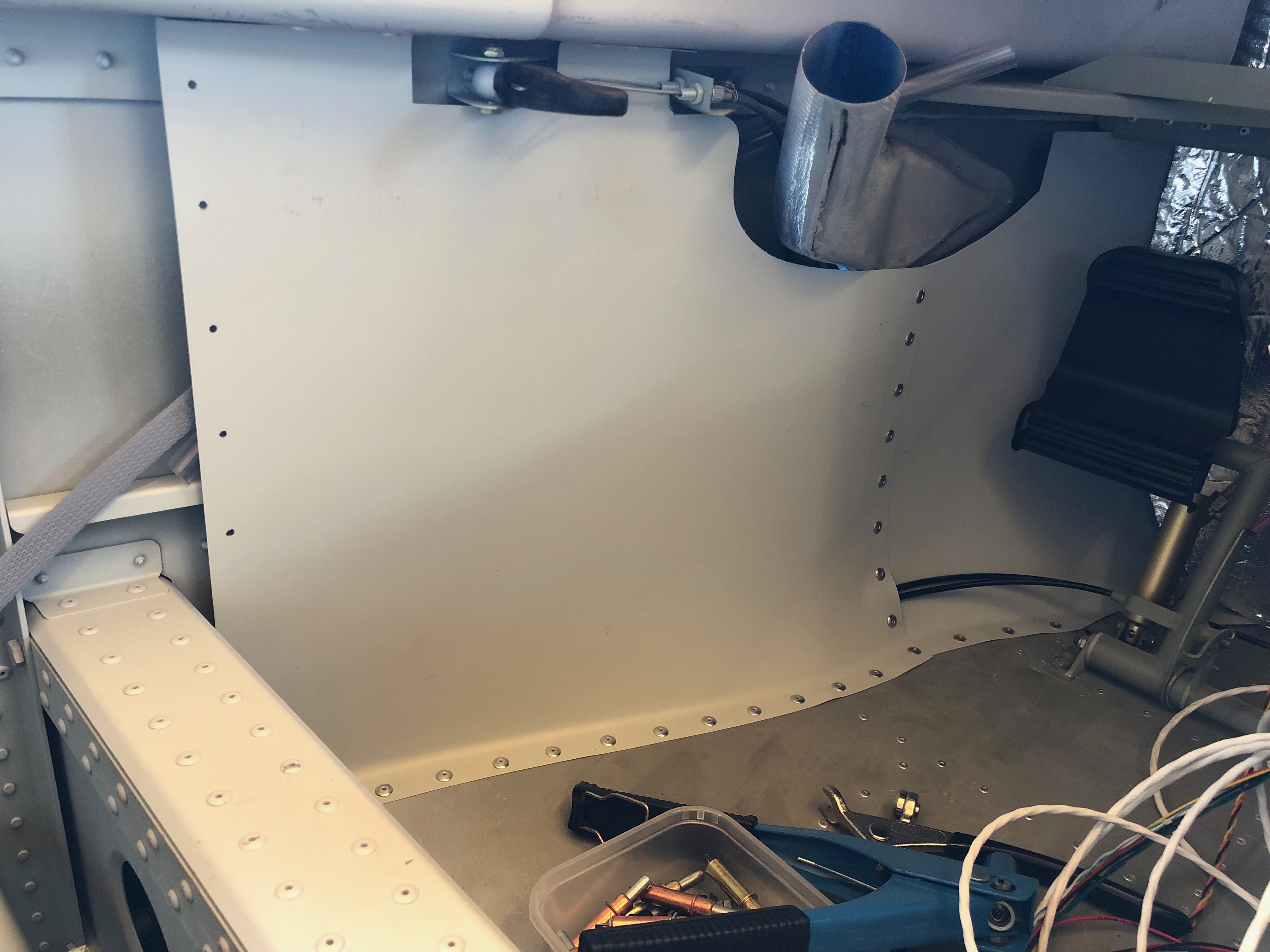
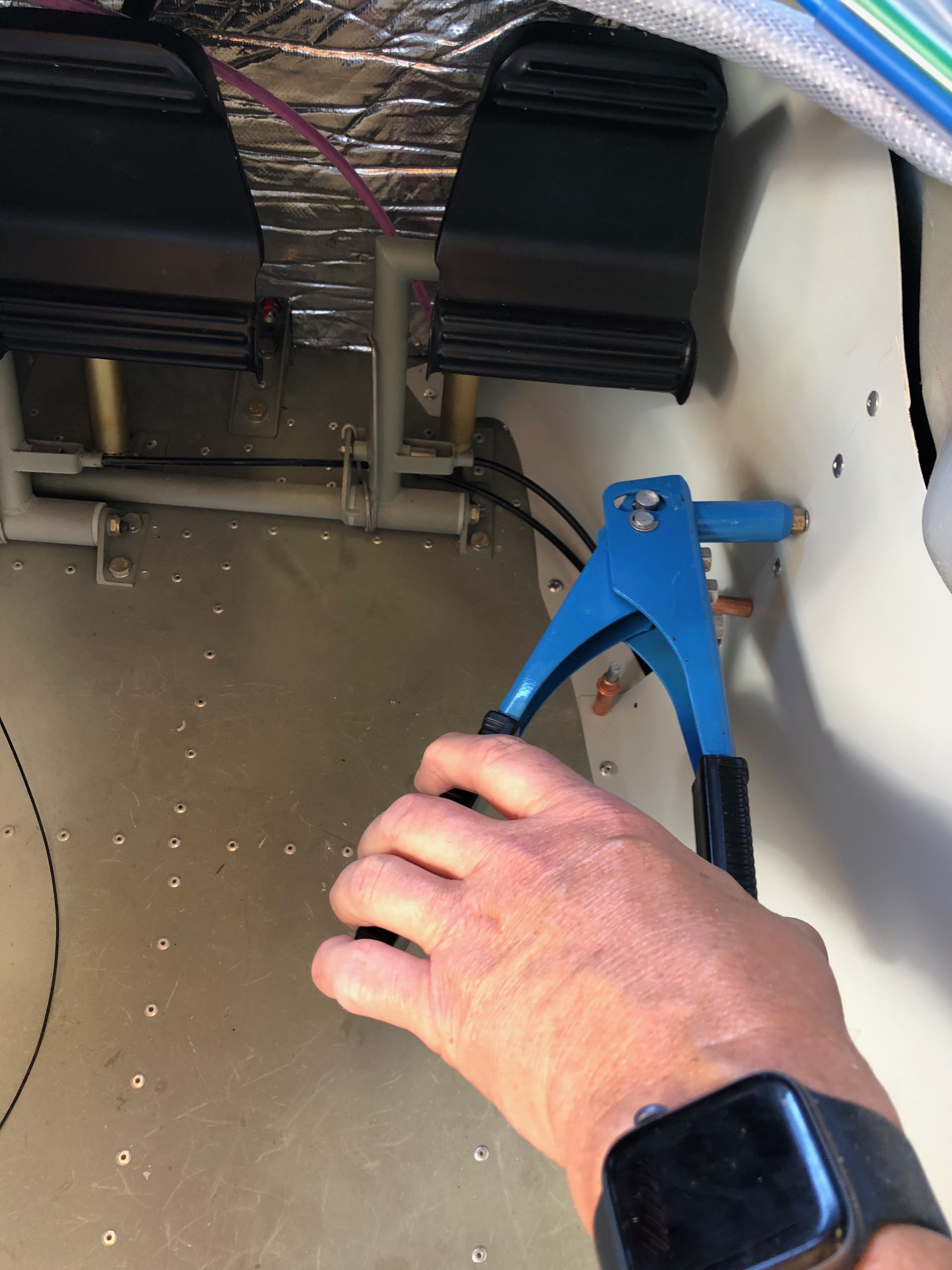
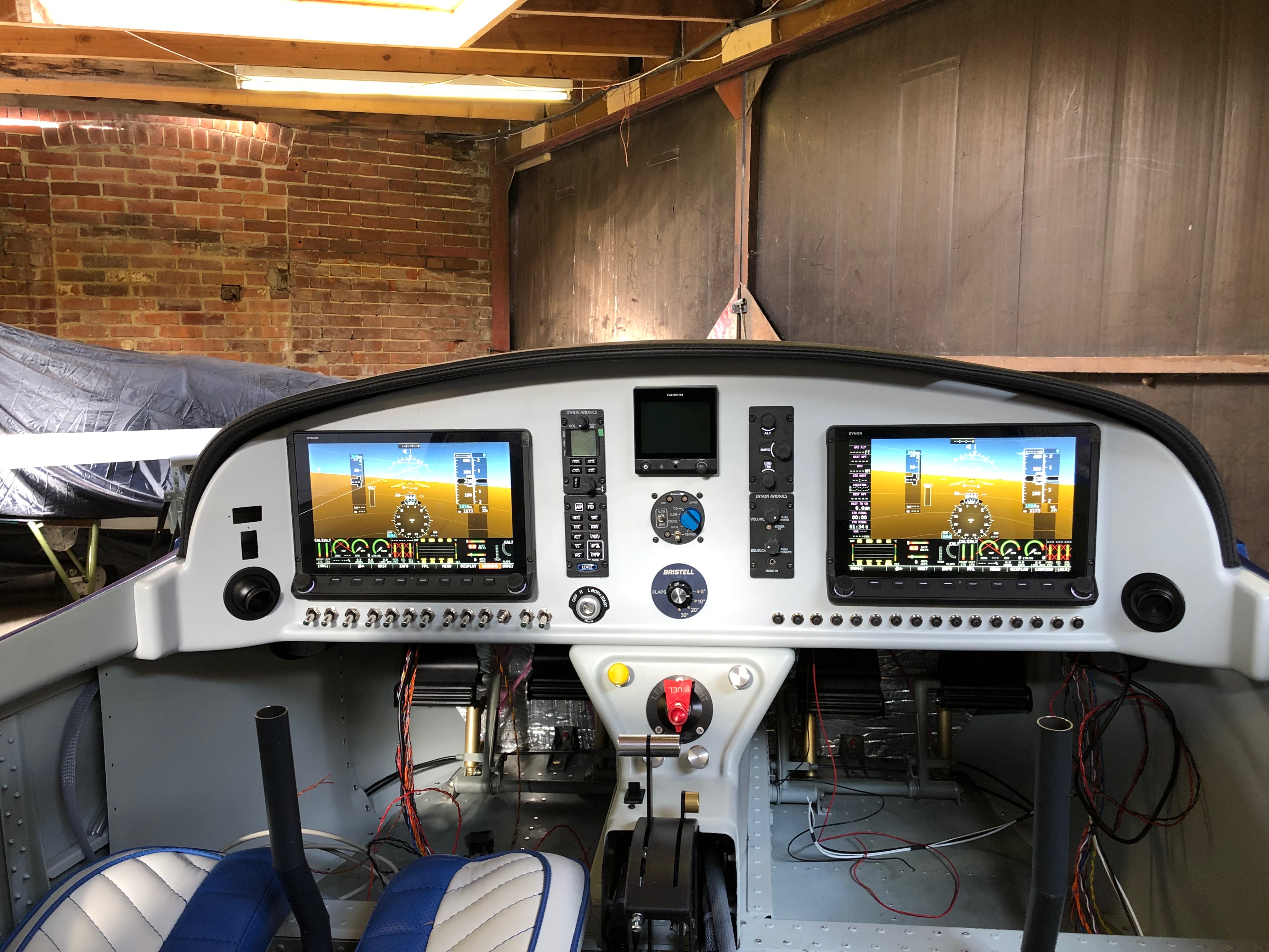
The aim for today was to finish adding the instruments to the panel, install the left and right footwell trims so I can install the instrument panel and get rid of the myriad of associated boxes and packaging!

The spinner of the Airmaster which would look even better on the front of the aircraft. The only problem is I don’t have all the components to fit it. I found out today that I’m missing the M8 Round-Neck Nut Set (of course I am!) They’re not supplied with the engine and not supplied by the propeller manufacturer! Quite amazing really. However a call to CFS Aero and a set are on the way to me for tomorrow.
The G5 has now been installed and one of the Skyviews.
The interior footwell panels are pre-drilled which makes it easier however they still need trimming and you need to make sure you know how they are fitted before starting to rivet. I’ve used some Clecos to secure the panel before riveting.
On the rear panels I’ve made them removable but these don’t need to be removable so I’m riveting them.
Of course one was easy to fit and the other took ages…
However all done now and looks quite neat. There’s carpet to cover the floor area which will make it look a little less utilitarian!
Now that’s done and the panel is complete it can be fitted.
It’s secured with 2 screws either side of the panel and 3 screws that screw into the centre console. It provides a very secure fit but may benefit from a couple of lightweight supports at the top of the panel.
The final panel, all the network cables have been fitted and the glare shield fitted temporarily and powered up using the backup batteries. The G5 backup battery has finally run out so I can’t switch it on which is a shame but overall I’m pleased with the result.

Monday 3rd June 2019

Music: Röyksopp

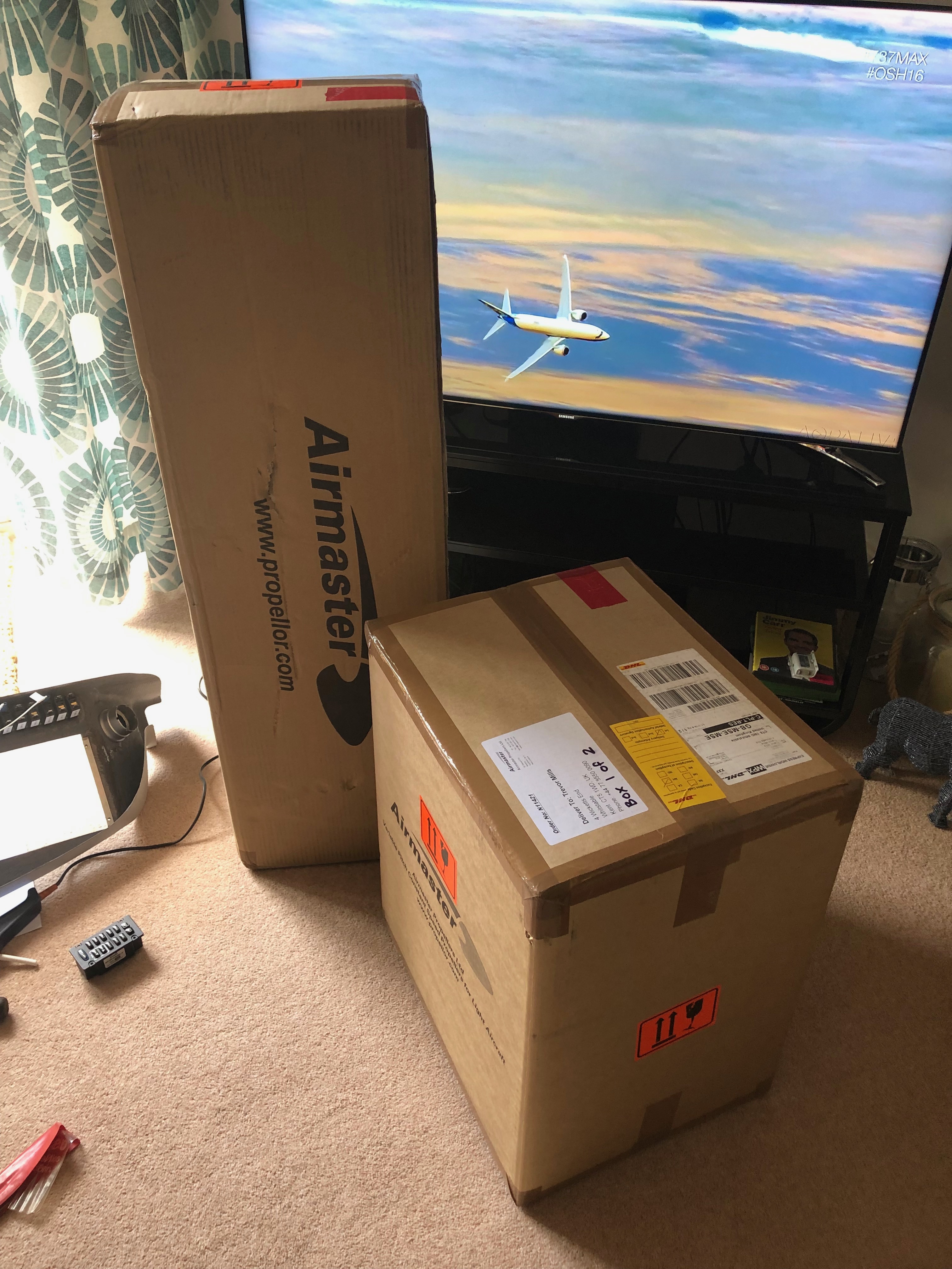
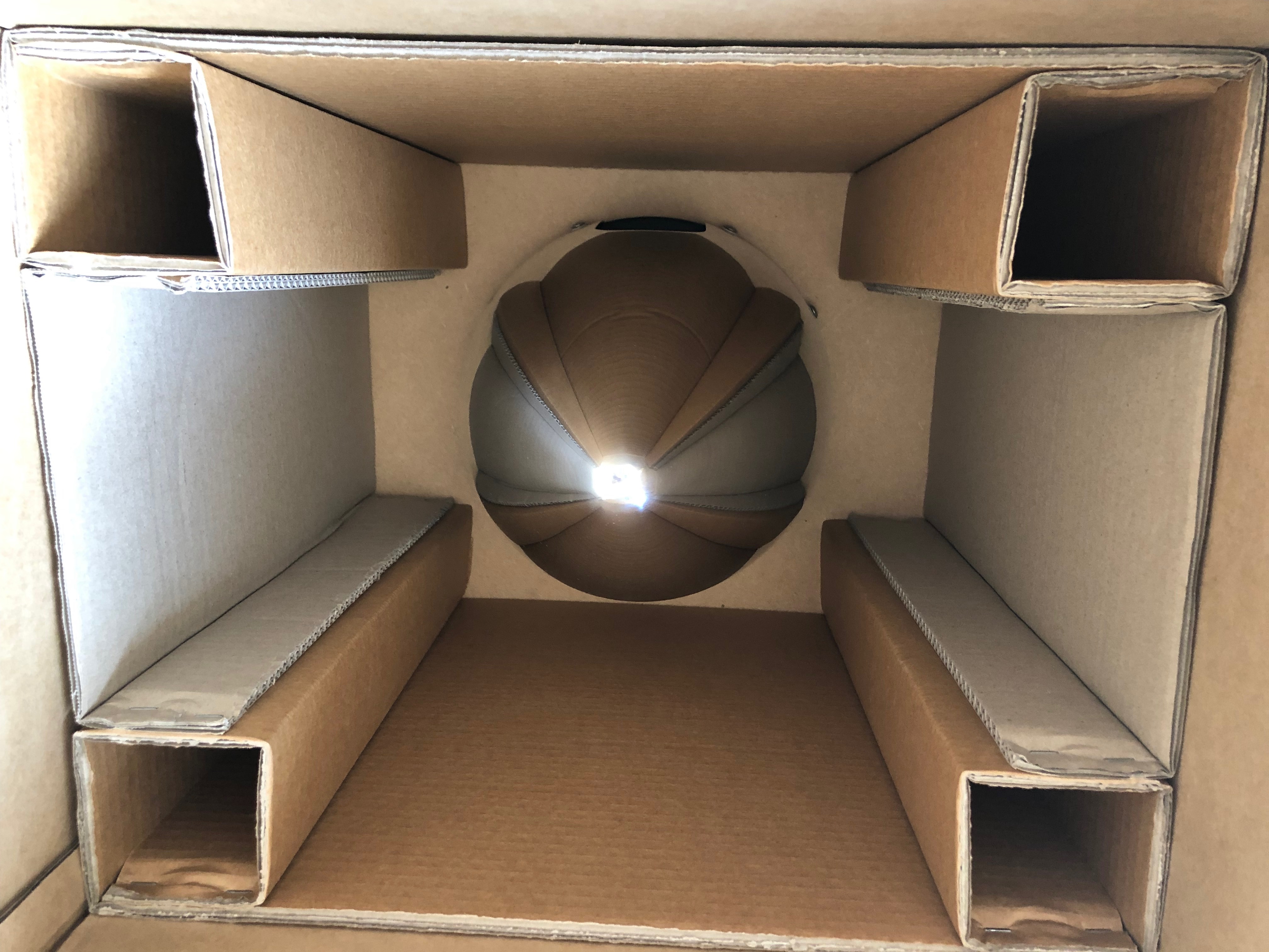
Good news – Today I’m expecting delivery of the Airmaster prop that was ordered in February. So I had brought back the switches and circuit breakers and thought that whilst waiting I would wire them up.

Each circuit breaker is linked to one or more switches depending on the circuit design by making a connecting wire with 22 or 18 AWG wire with a couple of crimped female spade connectors.
The Aveo air vents were next and are secured by screwing the front and back components together.
At last! I have finally received the Airmaster prop. On first inspection the hub and spinner box looked fine and undamaged and the inside…
looks good too…
However the box with the blades in had quite a substantial gash in the front.
Luckily, although the cut went through both the outer and inner boxes, whatever caused it never hit the blades – Phew!
One of the carbon fibre blades, looks very swish.

Tuesday 28th May 2019

Music: Elton John and Turin Brakes

A few jobs today. Bond the switch plates to the panel, start populating the panel with switches, mark and drill the ignition switch hole, create the looms for the servos and solder to the respective servos.

The panel cutting is largely complete now with just some USB data and power ports to add and an ignition switch. I’ve sprayed it with the paint matched to the interior so it’s ready to have the switches added.
To ensure that the spacing was correct I marked and drilled the holes in a piece of 20 x 1mm aluminium and then drilled through the panel. This is now bonded to the back of the panel to give the switches a solid feel during operation.
I’ve riveted on a couple of spade tabs to the end of the strip just in case I need to use them for earthing.
The switches are installed and tightened with a 14mm ring spanner. Have to be careful here to line them up correctly and make sure that I don’t mark the paint!
I’m still awaiting the arrival of my ignition switch that’s on its way from Germany but luckily Ian had one that I could use to get the positioning right and drill the hole. Now they are in I can leave it to set before installing the circuit breakers.
Now onto creating the look for the autopilot servos. Dynon sells a servo wiring kit with 20′ of multicoloured wire of the correct gauge, it includes 2 female and 1 male D9 connector. There’s ample wire to make 2 looms from it so I’ve cut it in half and bundled the wires together in readiness for soldering to the servos and terminating with a female D9.
There’s a few things that’s important to remember when soldering;
1) Match the colours.
2) Make sure you slide on the heat shrink tubing before you start soldering.
3) Mark each end of the loom so you know what wires you’re working with.
Soldered and protected. The final bit is to slide another piece of heat shrink one the bundle to keep it all together and…
protect the loom with some conduit. I’ve decided to use split conduit from the servo to the throttle quadrant and then I’ll use poly sleeving from there to the connector block.
One of the things that I’m trying to do here is to keep everything neat and tidy for easier maintenance in the future if needed.

Friday 17th May 2019

Music: James Taylor and Oh Wonder

A couple of days away to do some flying and meet up with an old mate for a beer or two and now back to the grindstone!

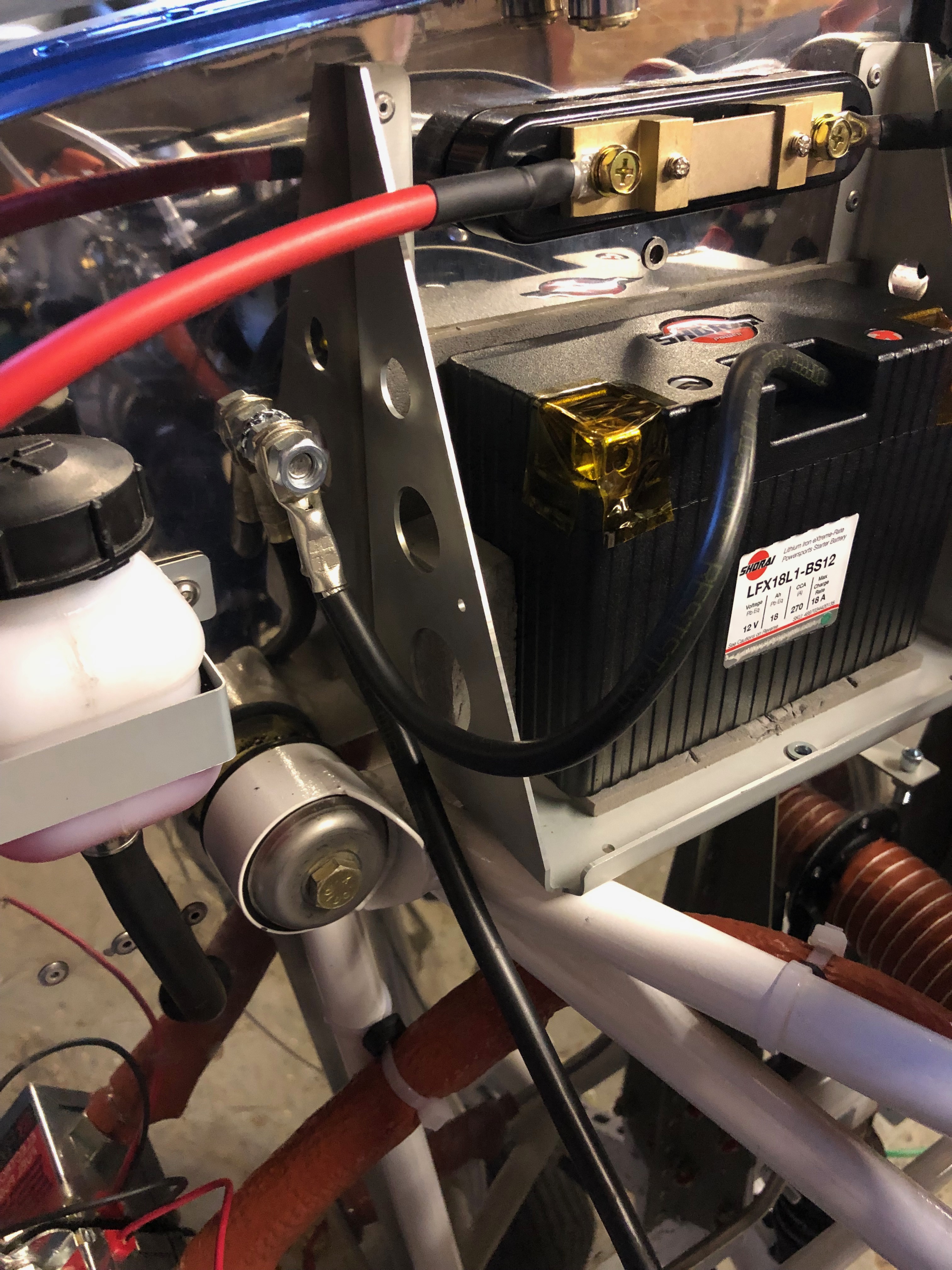
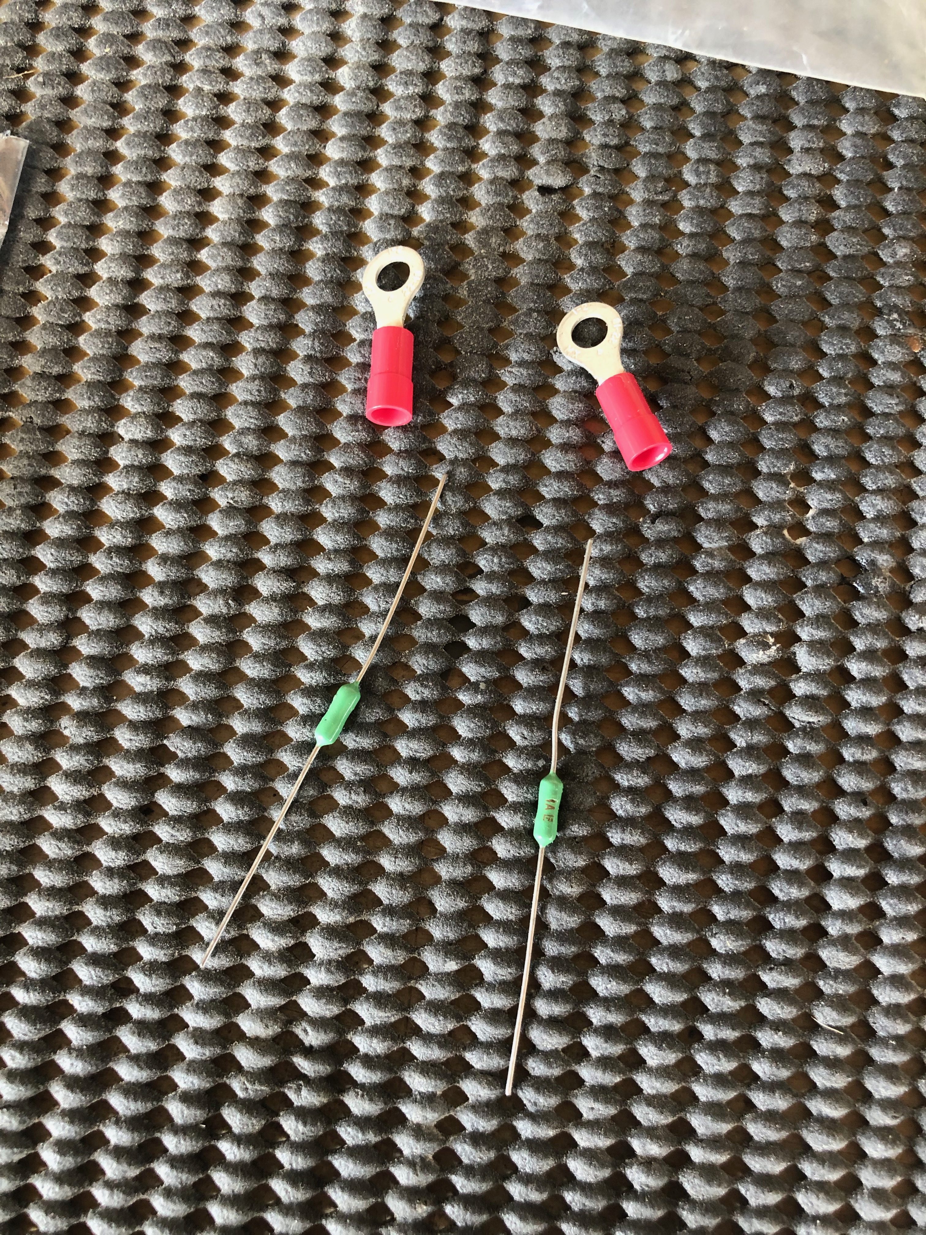
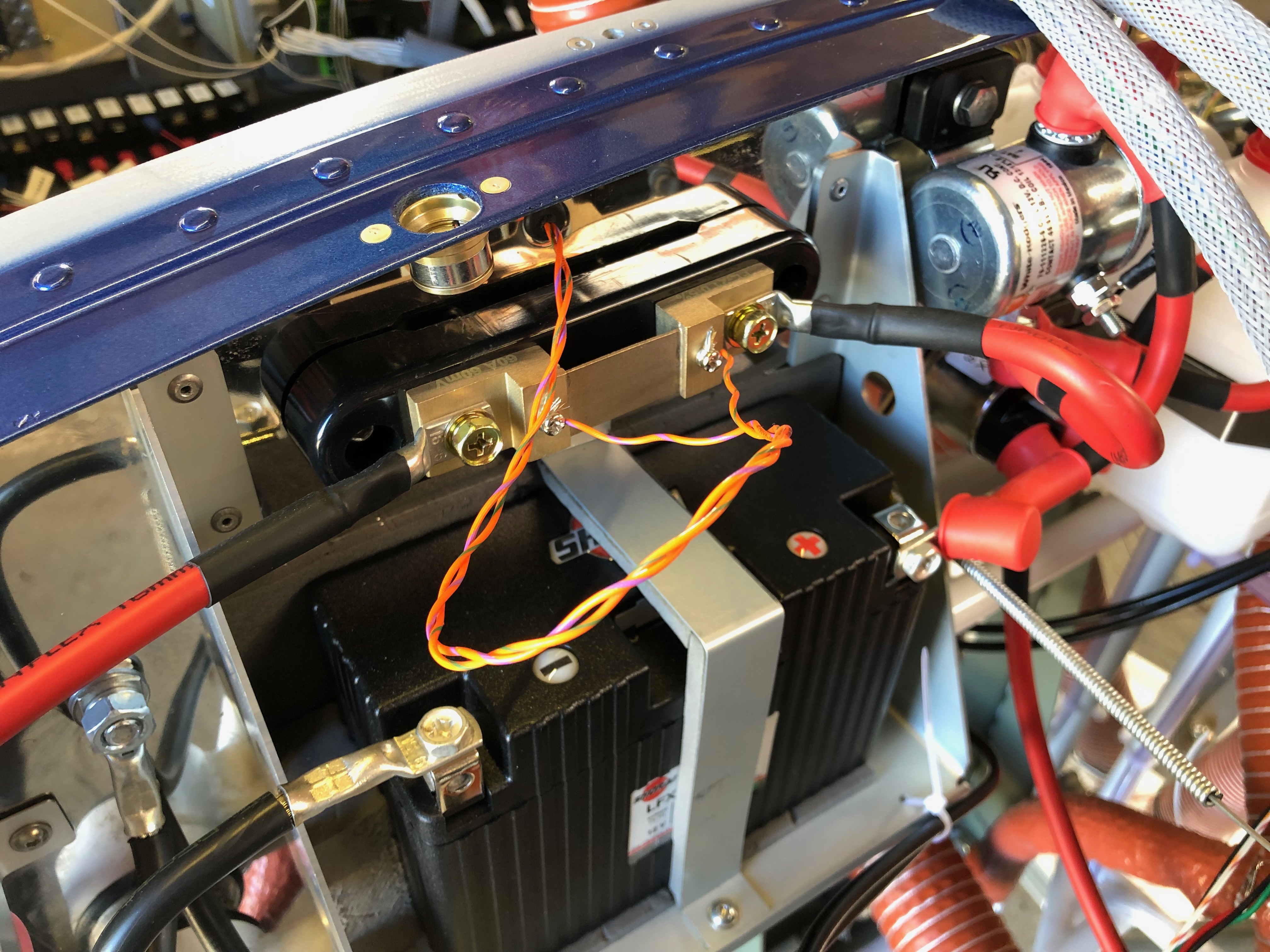
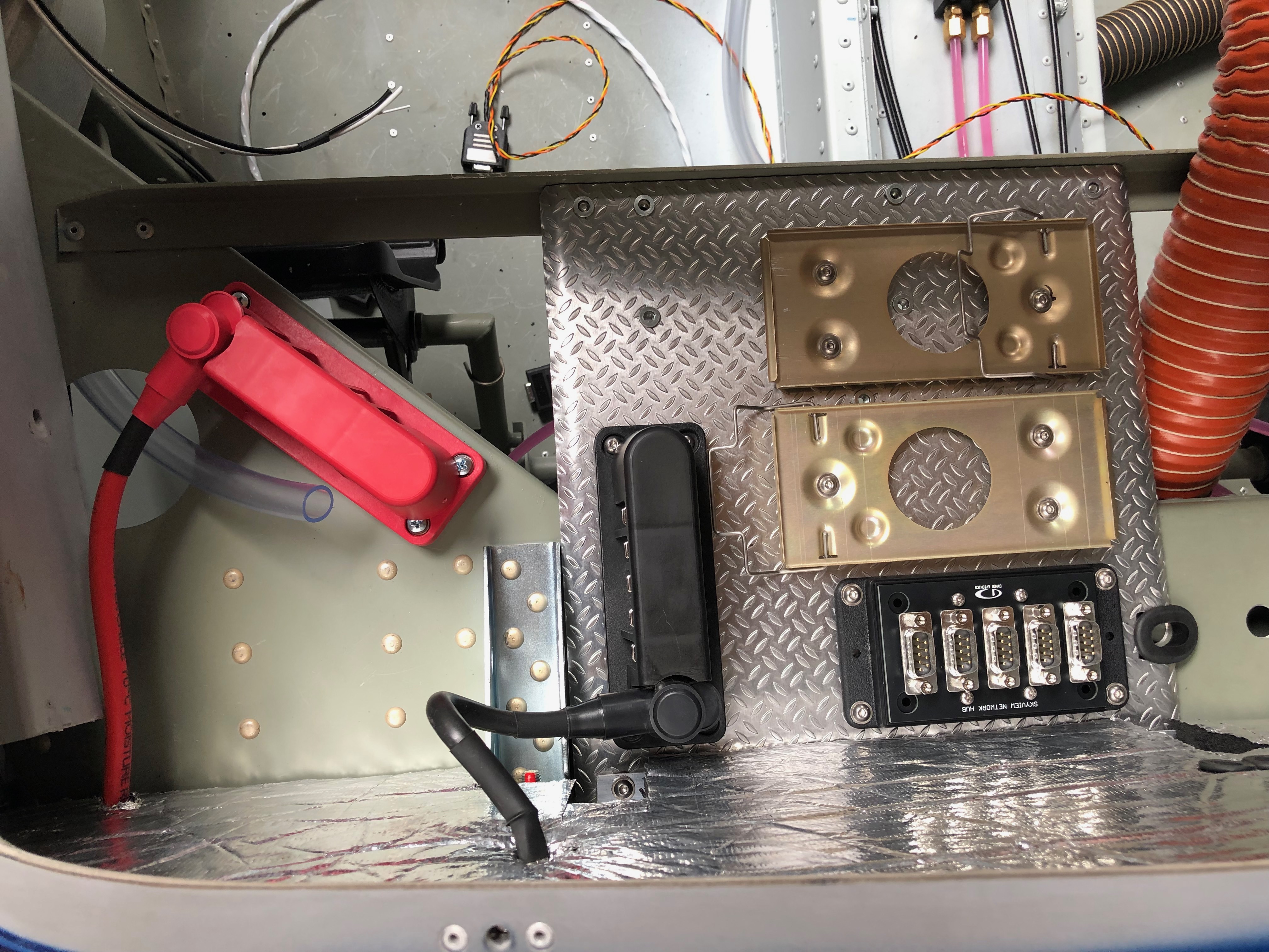
A couple of items to complete the installation of the primary power system. The power and earthing arrangements that I’ve decided to use necessitates rearranging the items on the comms tray. Once this stage is complete and with virtually all the other activities complete until the prop arrives it’s time to move on to wiring the all the systems together. It’s getting to the stage where I need to finalise my panel design and start cutting it out. I haven’t decided whether I will do it myself of get a company to water cut it.

I decided to use a neat 20 way earthing block (VTE 120amp busbar) that complements the power distribution block that I’ve already installed. Where to mount it was an issue but thought the comms equipment tray would work well and shouldn’t produce any interference. So an hour or so was spent trying to work out the best position to ensure ease of access and sensible wiring runs.
I think this is the best option. I made up a short earth wire terminated with and 8mm on one end to bolt to the firewall earth stud and 6mm the other to connect to the busbar. This solution will provide 20 feed and earth connections that should be adequate as I have 15 circuits to cater for in the current electrical design.
The last wire to add is an earthing strap that is bolted on to the starter motor. This will ensure that the start draws all it’s power from direct connections and not through the aircraft frame or engine mount .
The completed primary power system.
Onto running the wires and harnesses in that I’ve made into the aircraft and ensuring that they don’t get damaged during service. This is the ADAHRS network cable. I’ve chosen expandable braided PET cable sleeve. It’s tough, very light and is easily installed.
Once the cable is run in it can be secured with cable ties. This will be hidden behind the interior panels that I’ve decided to make removable so I can get to these when I carry out my annual checks.
For harnesses with connectors on I’ve chosen flexible split conduit which is tough, and light but a little more bulky. The split in the conduit allows me to slip it over my pre-made wires.
With all the wires and services that will eventually be installed I have to make sure that the installation remains neat and tidy that will facilitate easy maintenance, good protection of the various services and easier fault finding if I ever have a problem.

Tuesday 14th May 2019

Music: Oh Wonder, Paolo Nutini

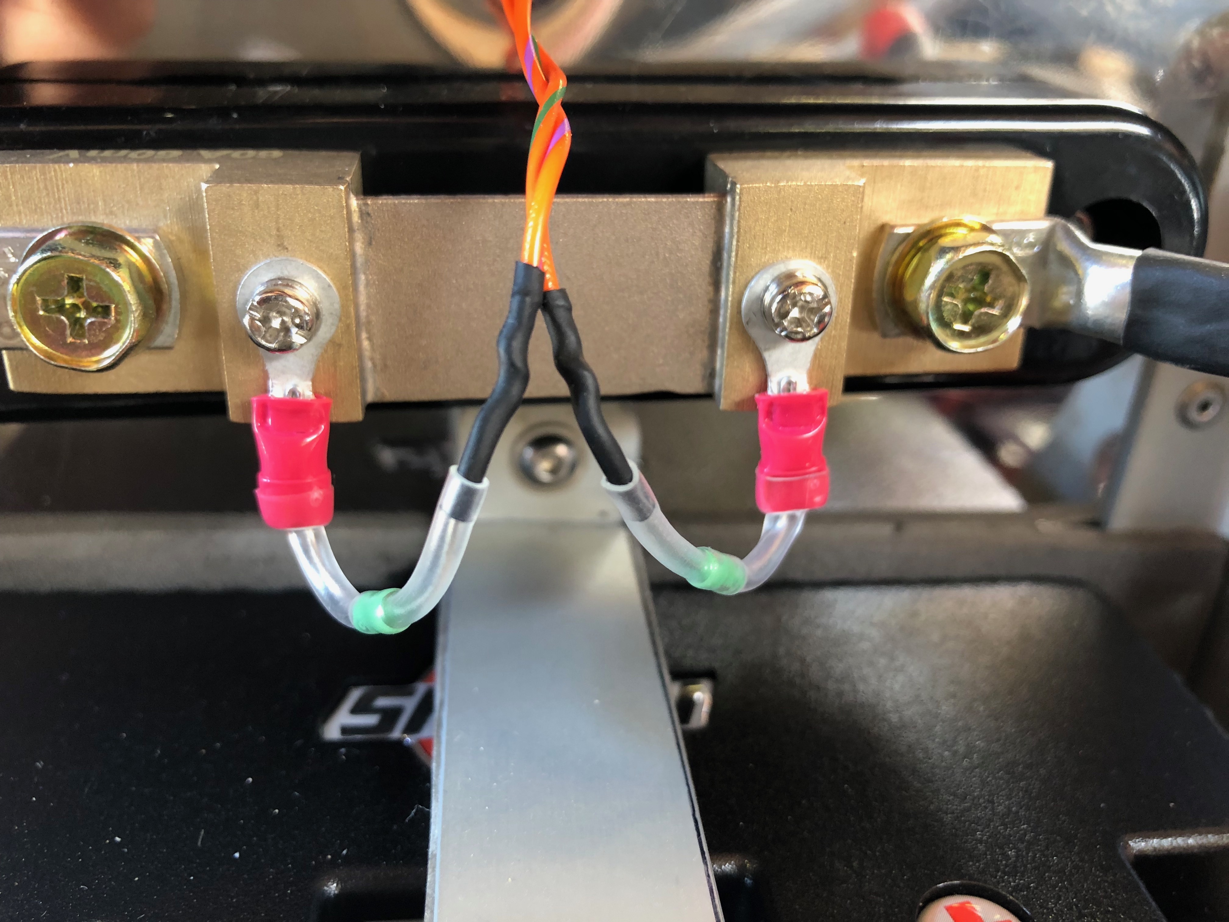
Today I focused on completing the primary power system and testing switch pitch layouts before fitting to the panel. Robin May and Dave Bennett came down for a visit and check my work out to make sure it was up to standard after which we went for a quick lunch in the Prince of Wales pub that is just across the road from the airfield. It was great to see them both.

Rob and Dave sporting cheesy grins just before departure. Estimated time to get back to Finmere, just 33mins!
I mounted the circuit breakers using a piece of 20 x 1mm aluminium to check on spacing…
and then did the same for the switches. I will have more interaction with them whilst flying so need to make sure their not too close together. 20mm spacing seems to be fine but will do a final check before drilling the holes in the panel!
This is the likely layout of the switches. I’ve tried to order them logically based on start up and scan cycle.
Each of the heavy duty wires that are used for the primary power system need to be terminated. I considered ordering the wires but thought it would be better to make them up myself just incase I changed my mind on the positioning of components. This is a handy tool for crimping terminals on heavy duty wires that can be used by either clamping in a vice or hitting with a hammer. The latter seems to work a treat!
The +ve power needs to run through the firewall to a position behind the instrument panel so an additional hole needs to be drilled and protected with a rubber grommet.
After a lot of research and scouring the internet I found this busbar. The wire is connected to the unit and protected by a rubber boot, a cover fits over the whole unit to protect against shorting.
The +ve side complete. Now to move on to the -ve side and earthing arrangements…
The -ve needs to be attached to the airframe, engine and -ve busbar so I’ve added a stud that I can connect the engine and battery connections to. Thats it for today and quite pleased with the progress made however it all takes a bit longer than you expect!