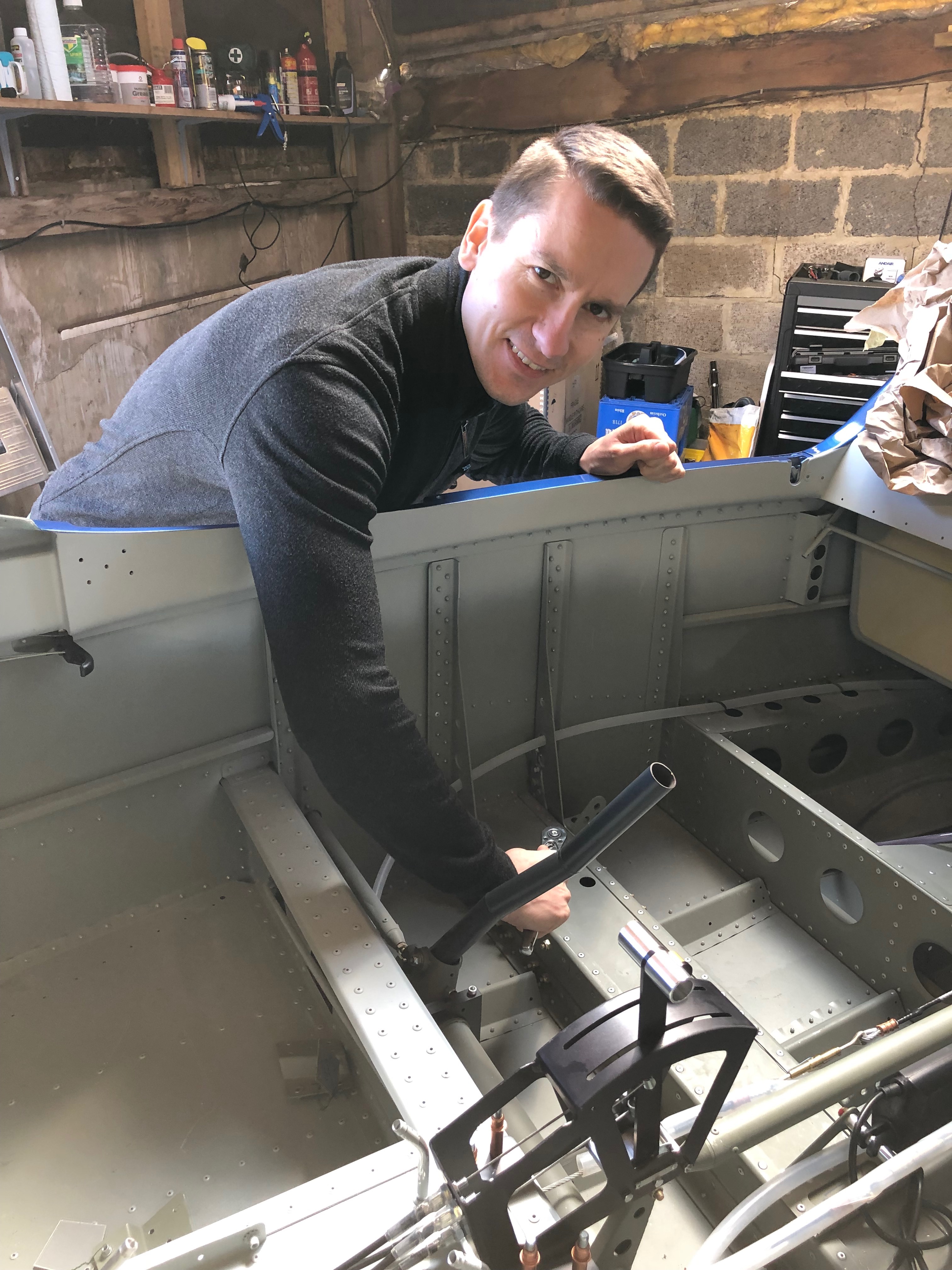
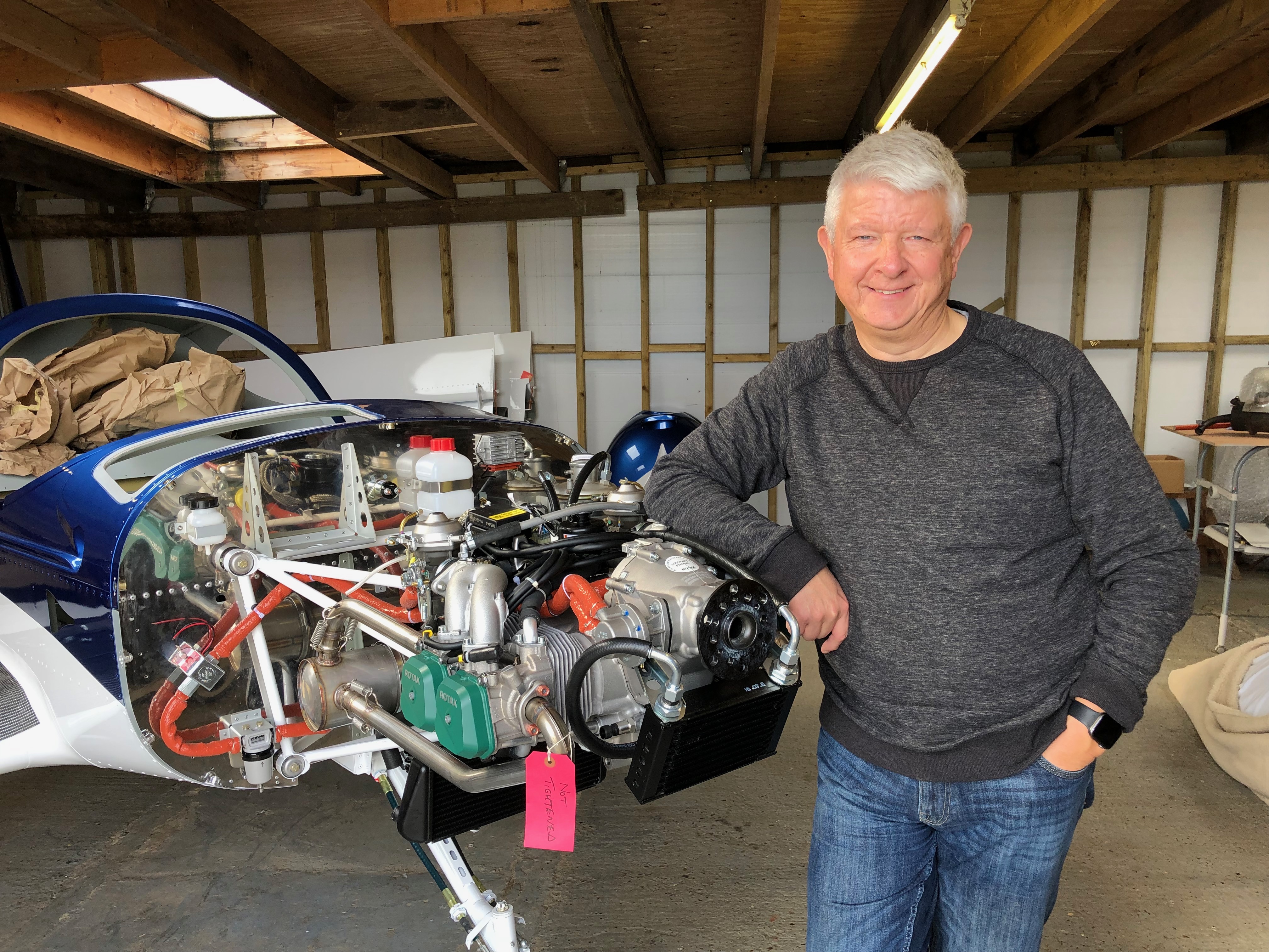
Chris came down today to visit, see the plane and help me do some of the jobs that require two people.
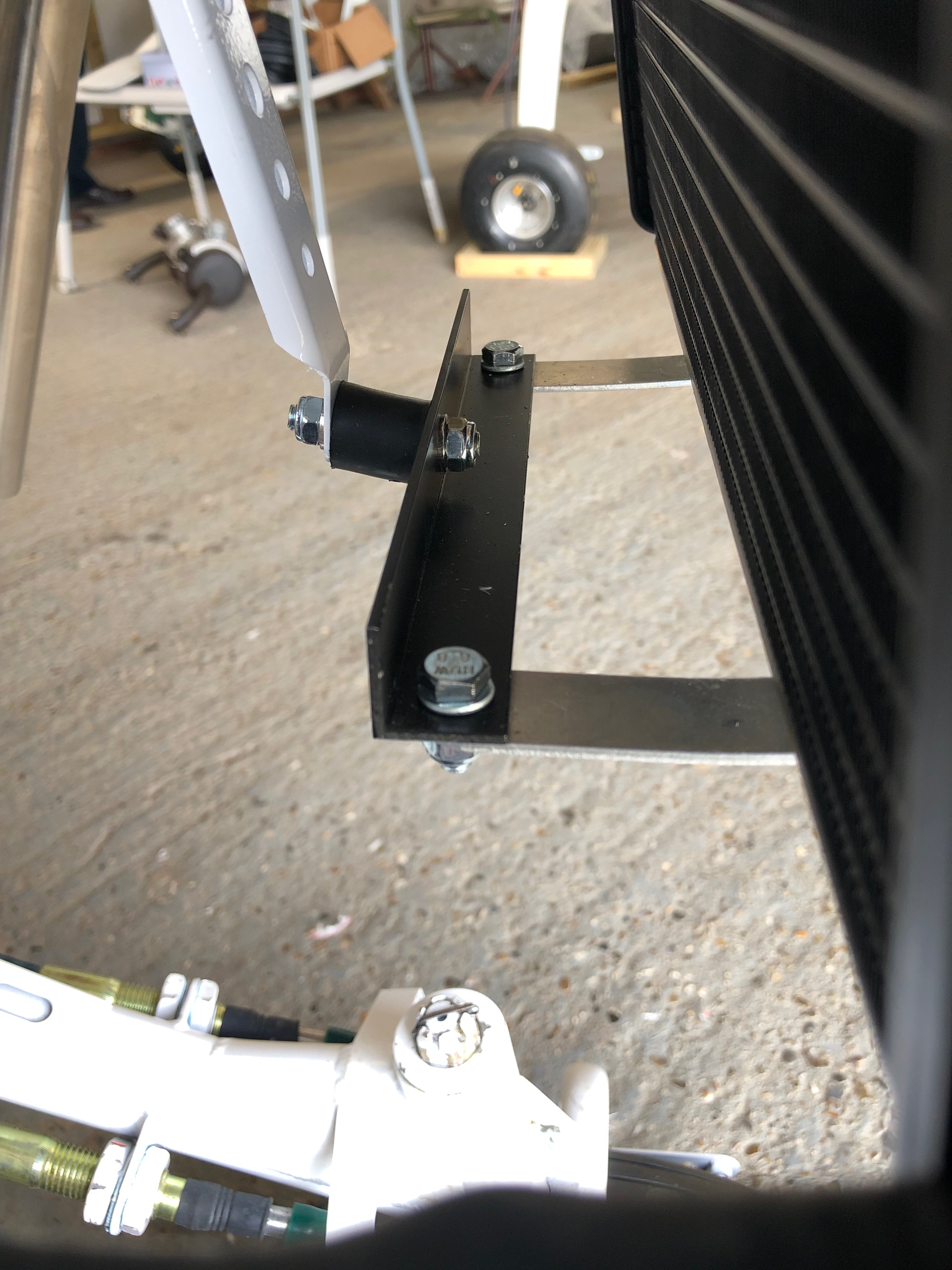
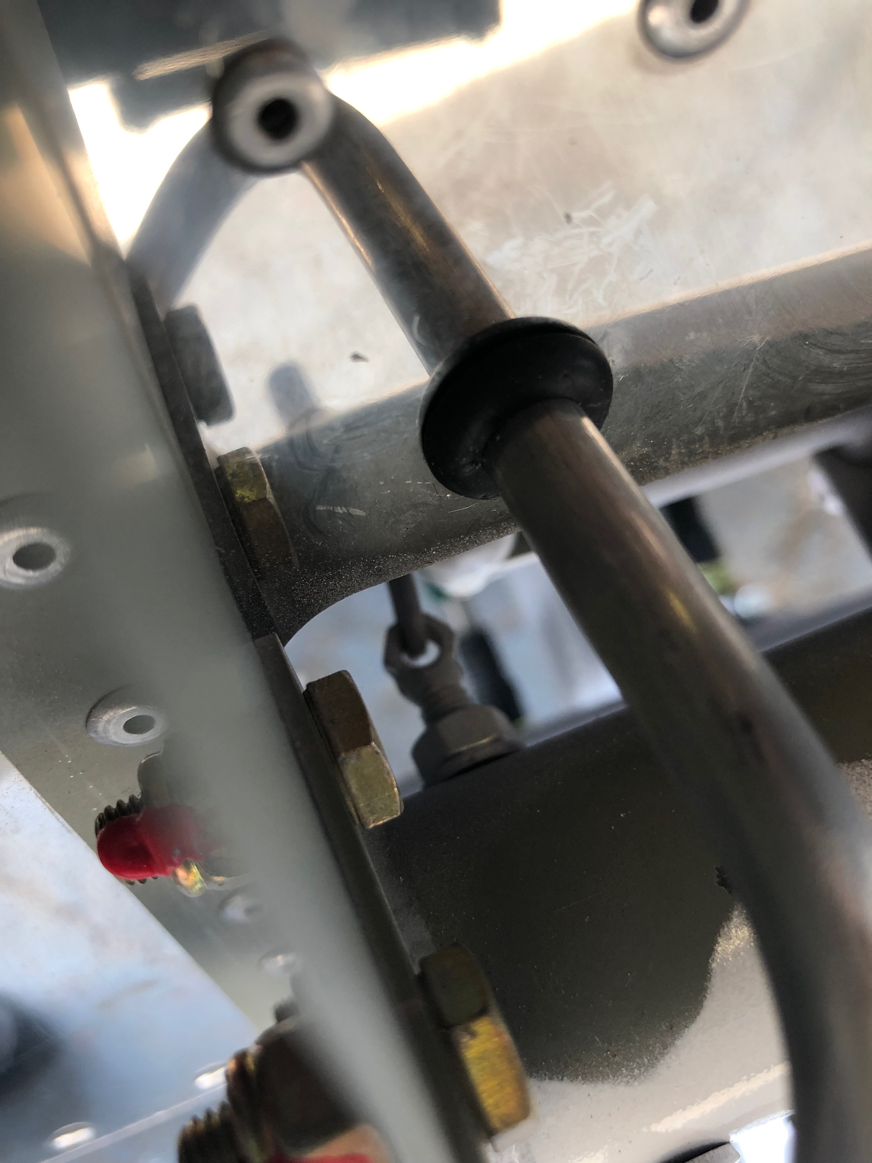
First job today was to check the undercarriage bolts for tightness. Unfortunately two of the four bolts did not tighten so were removed for inspection and were found to have damaged threads. These will need to be replaced.
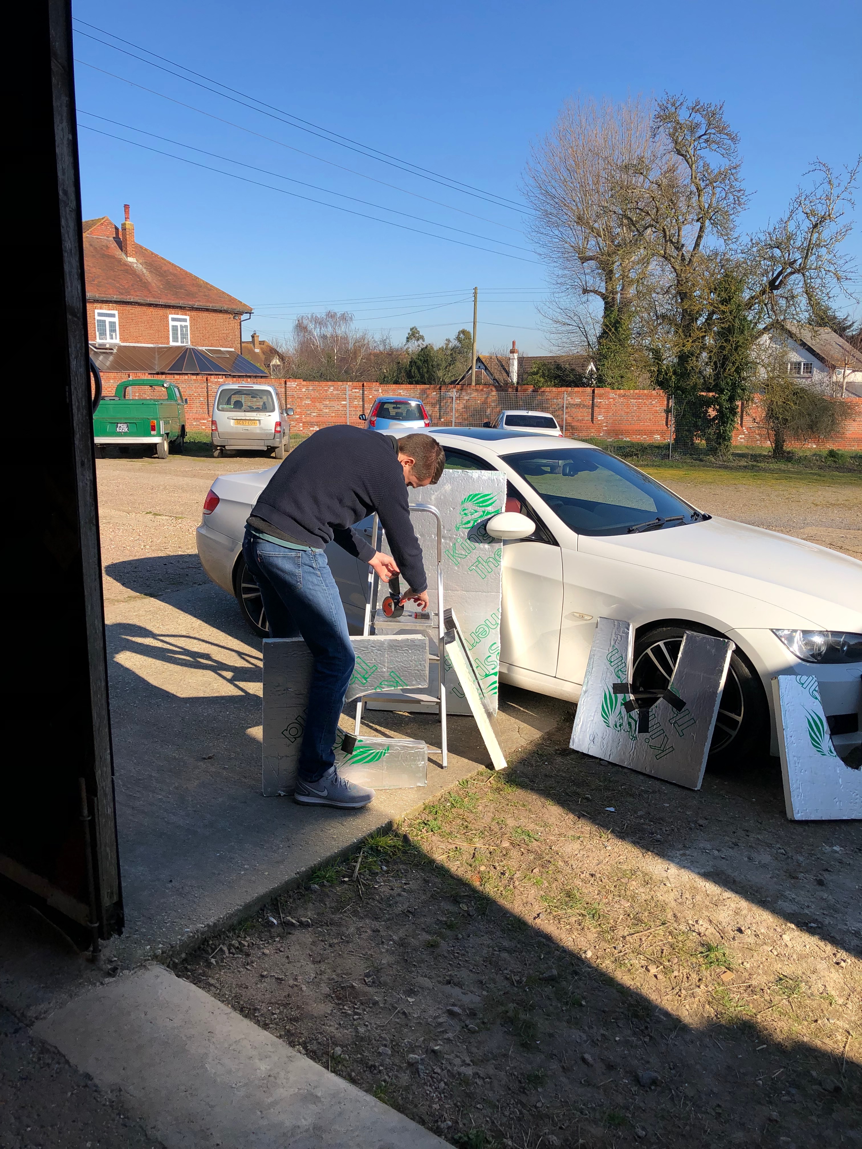
Chris making some wing stands .
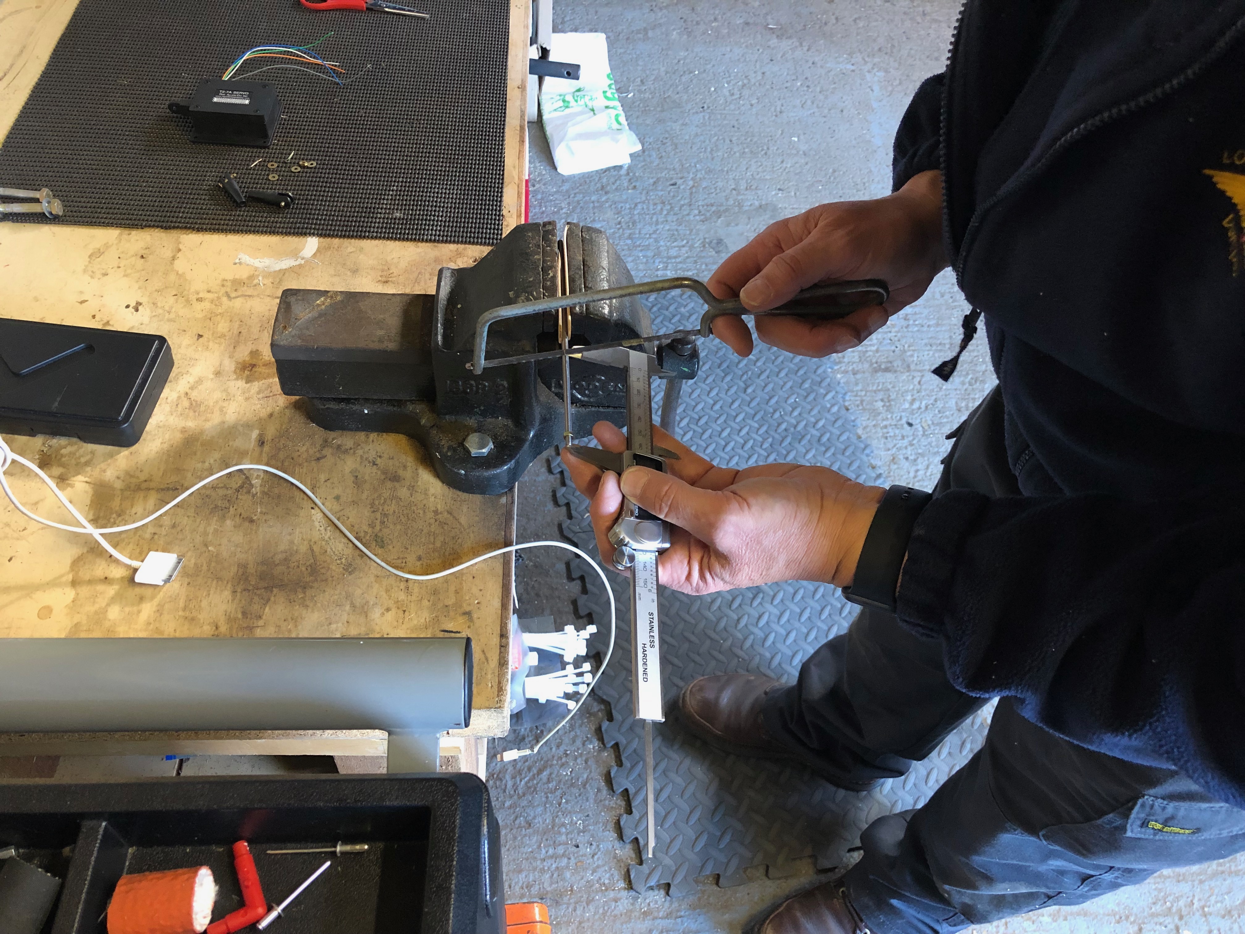
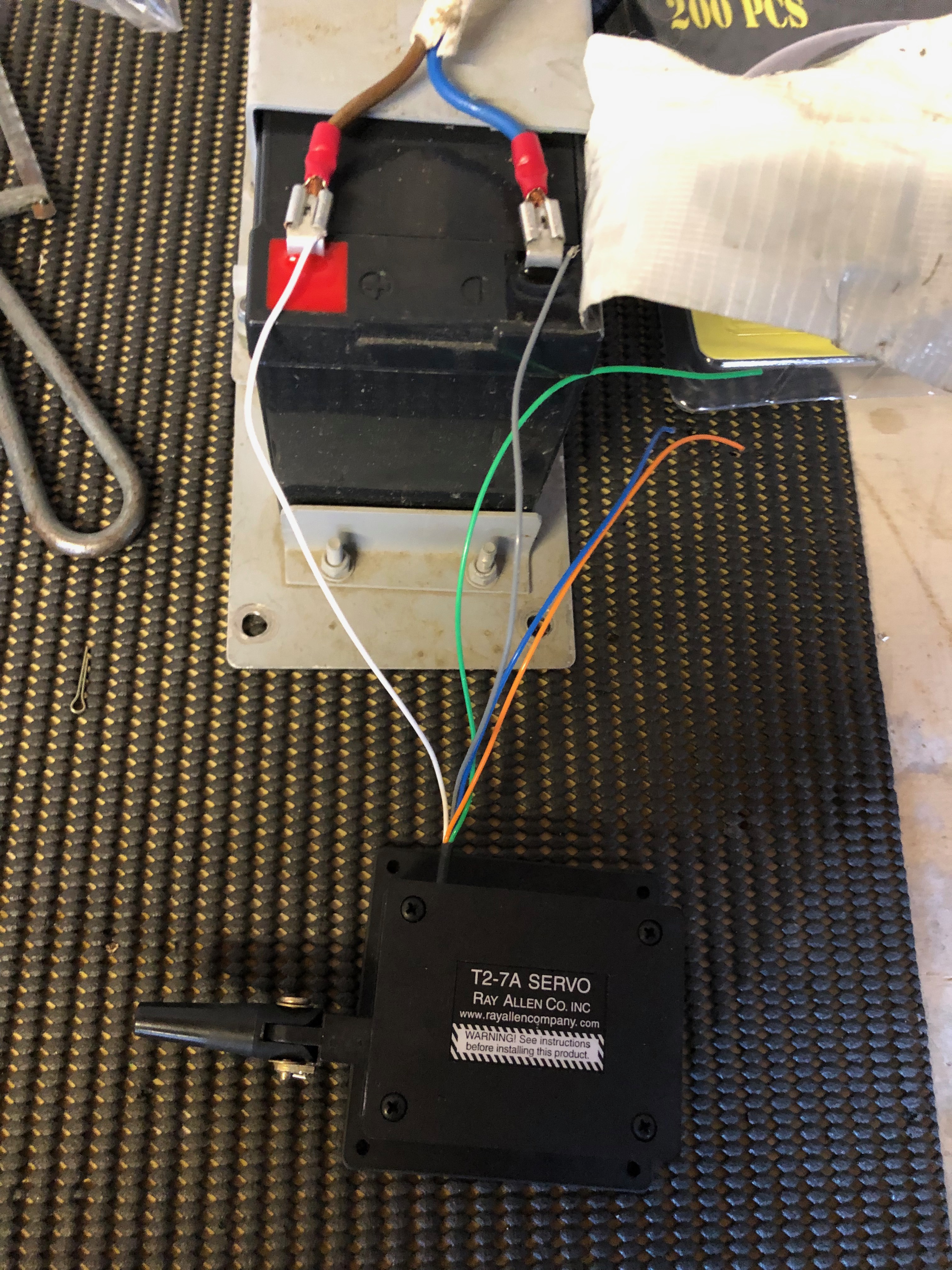
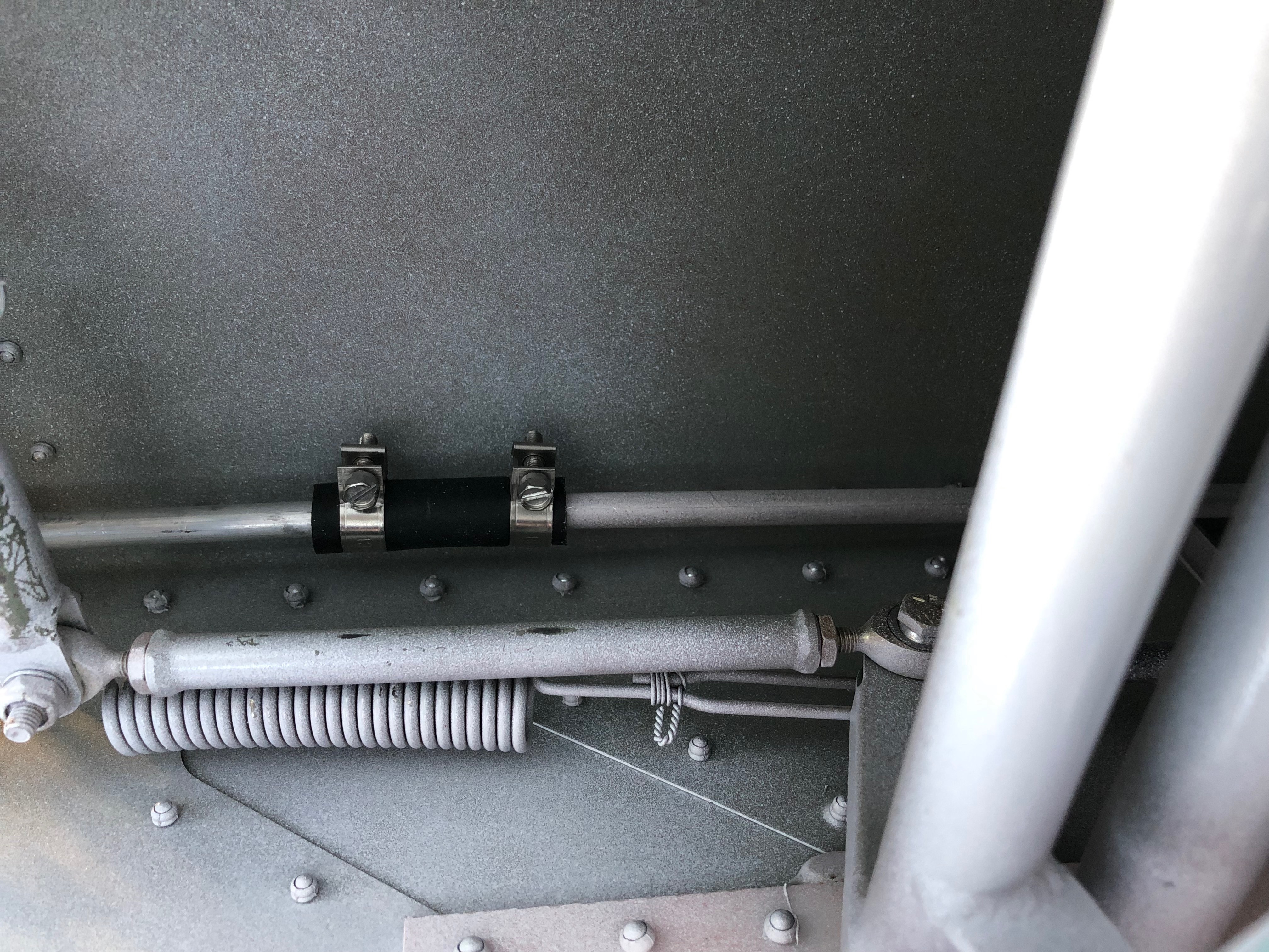
Our next job was to install the Aileron and Elevator trim servos.
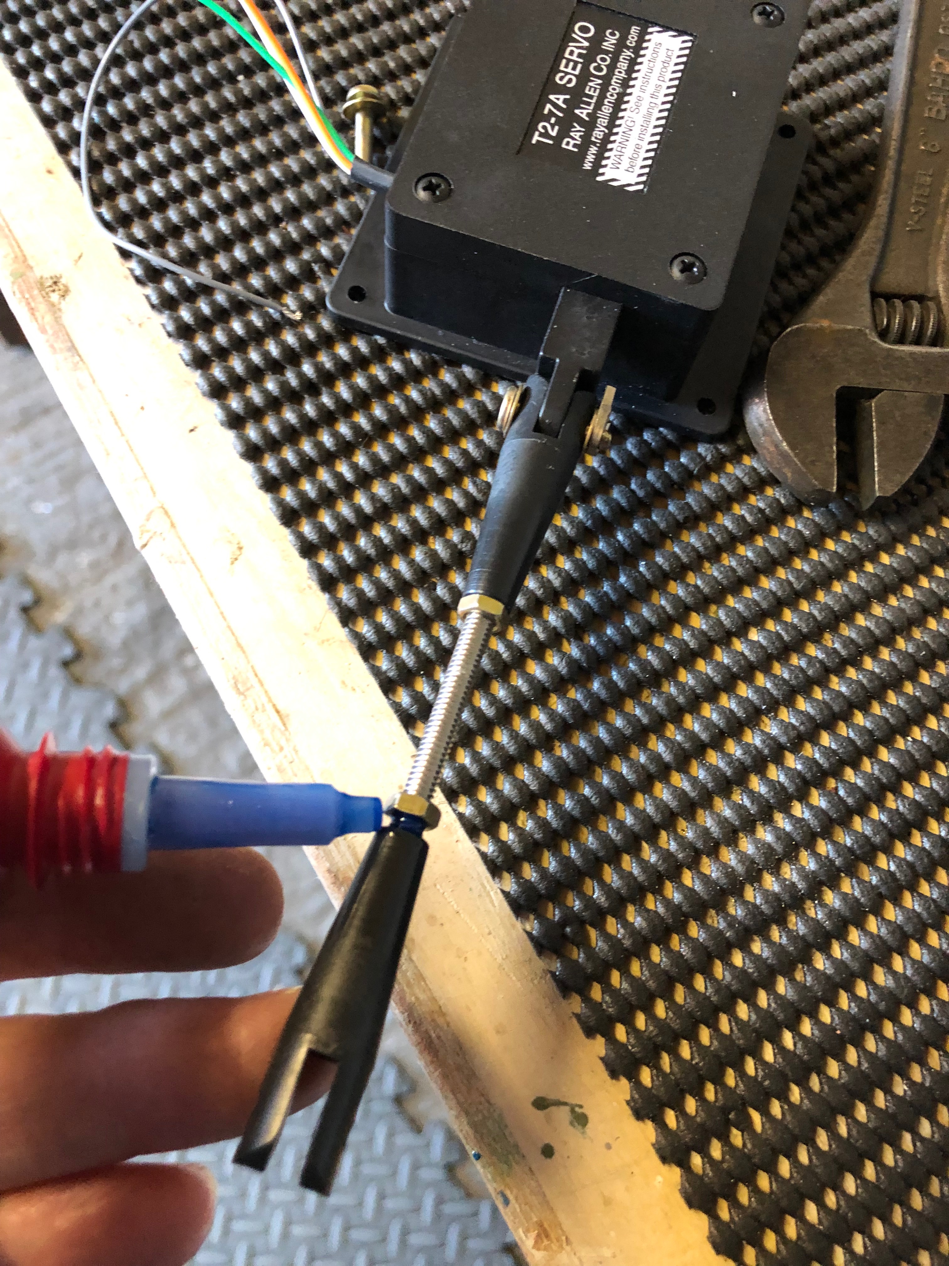
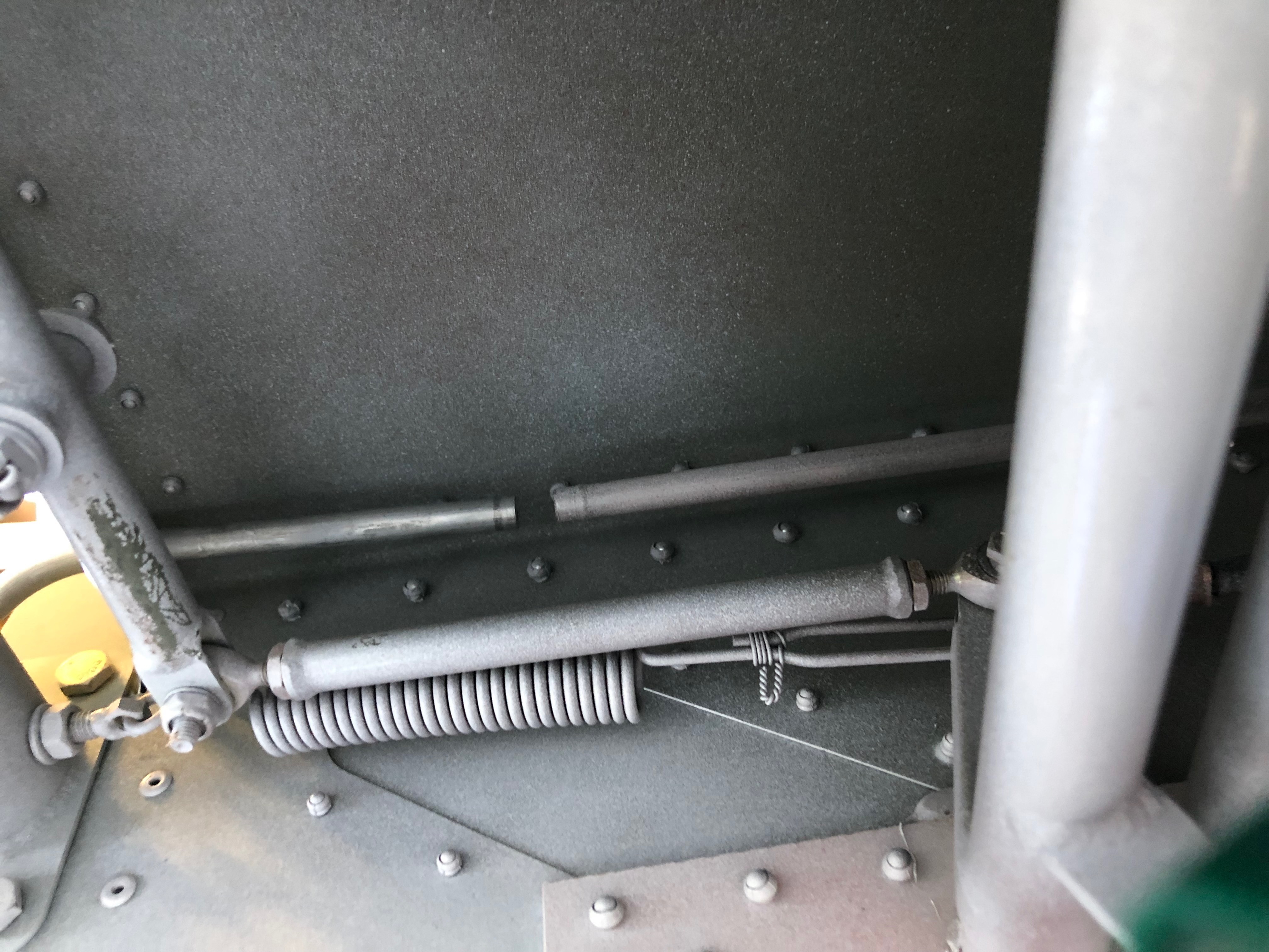
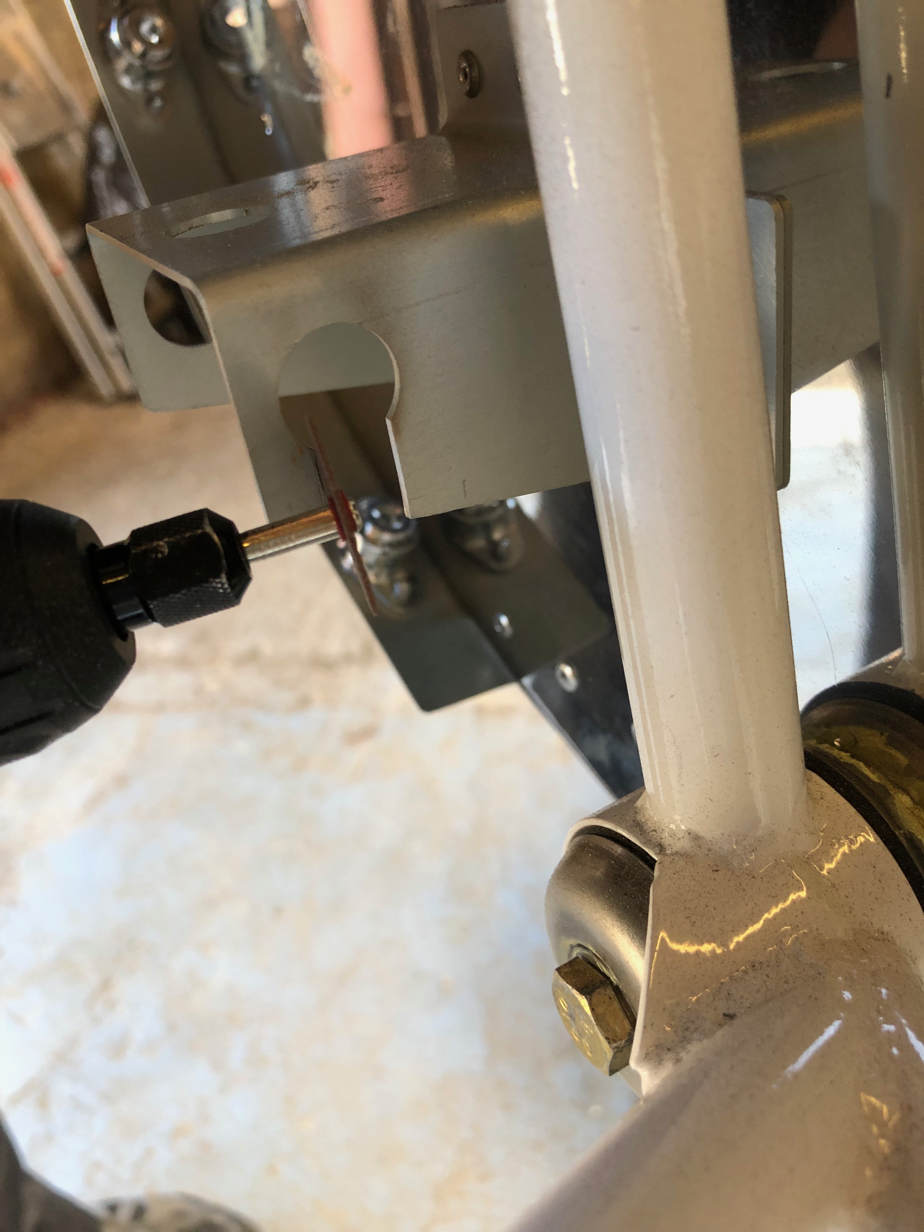
First job is to cut two threaded rods one 85mm for the elevator and one 65mm for the aileron.
The clevis is added and secured with a split pin.
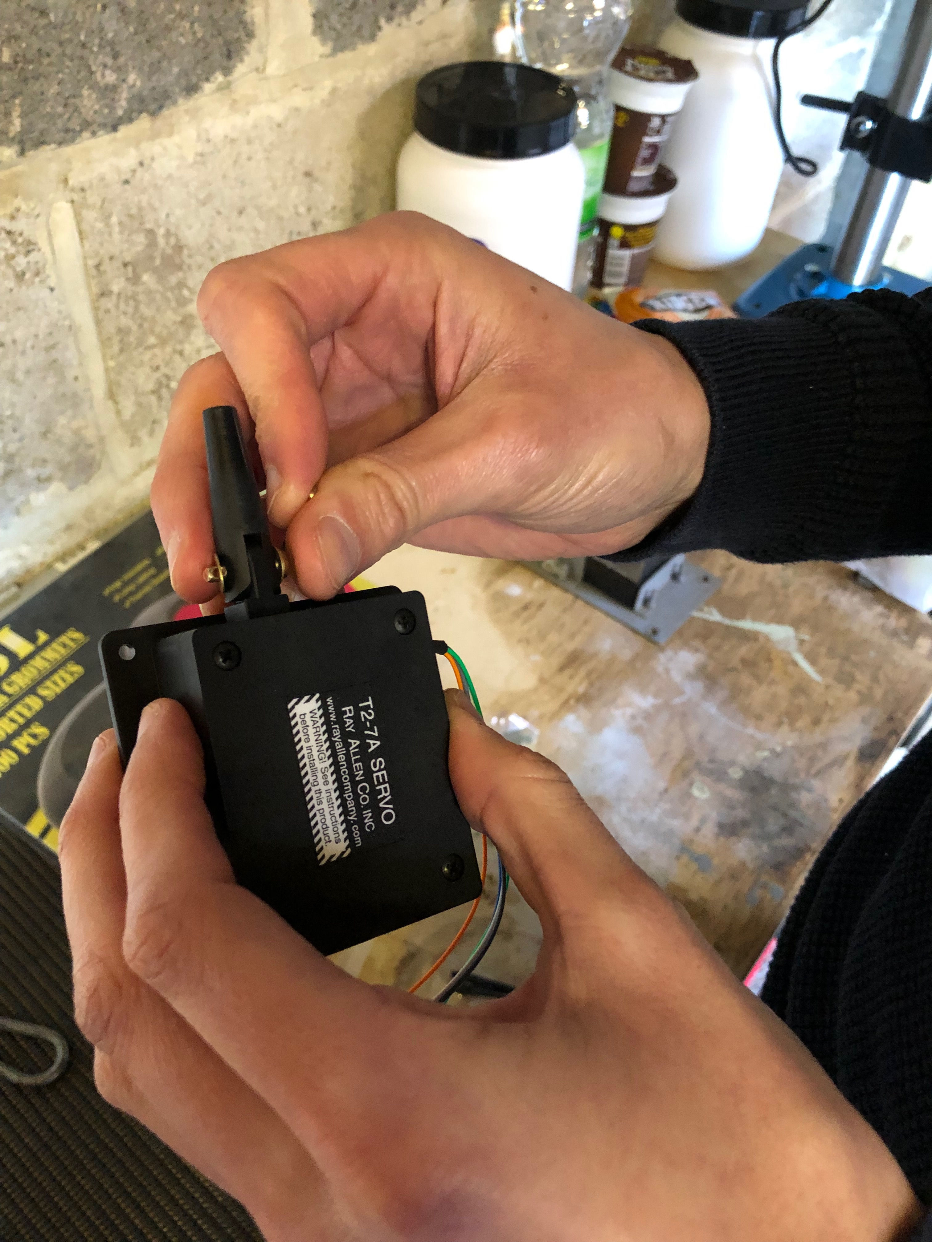
The servos need to be moved to mid position which can be done with the aid of a 12 volt battery. The white and grey leads can be connected to the battery in either polarity to move the servo in or out.
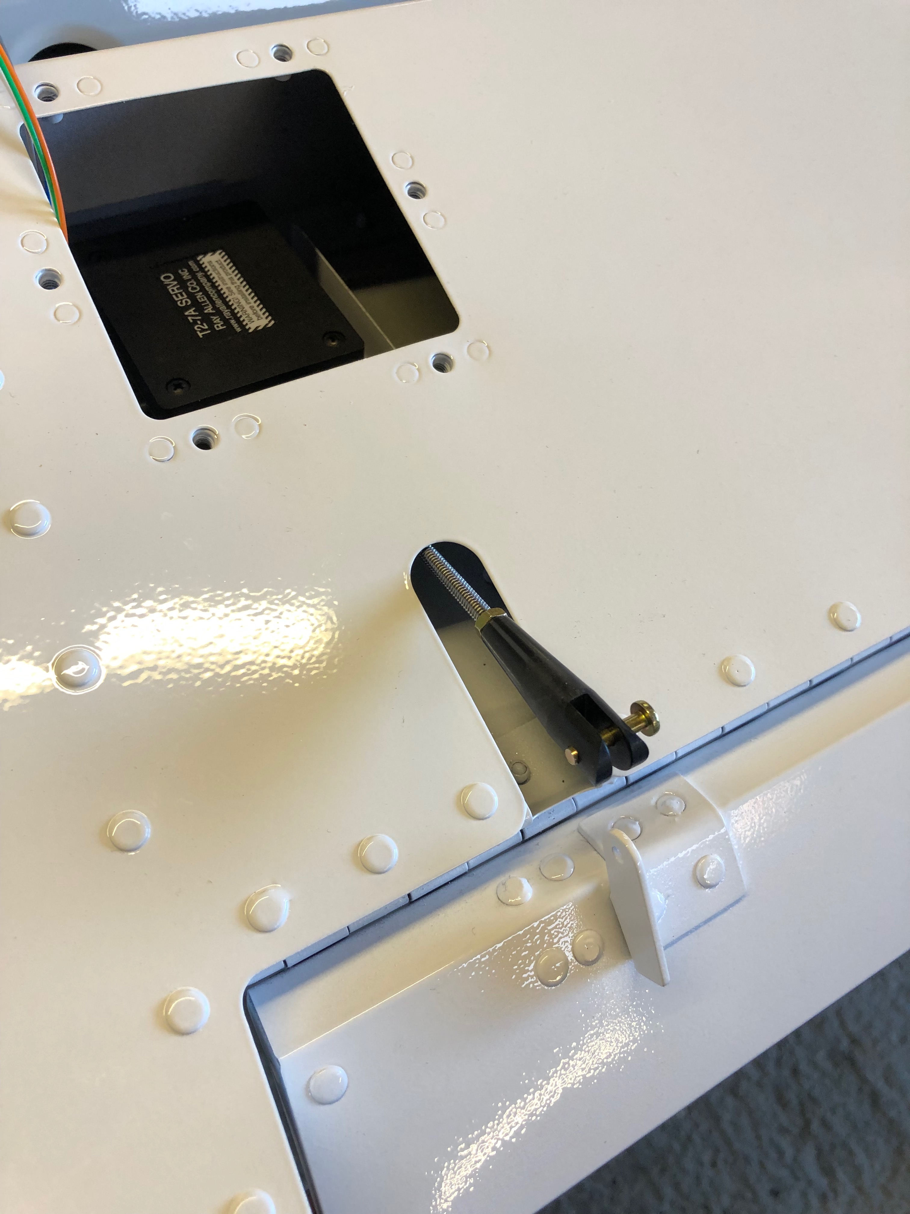
The servo is positioned in the recess and cleco’d in place so the control rods can be adjusted correctly.
Once adjustments are done the locking nuts are secured using Loctite 243.
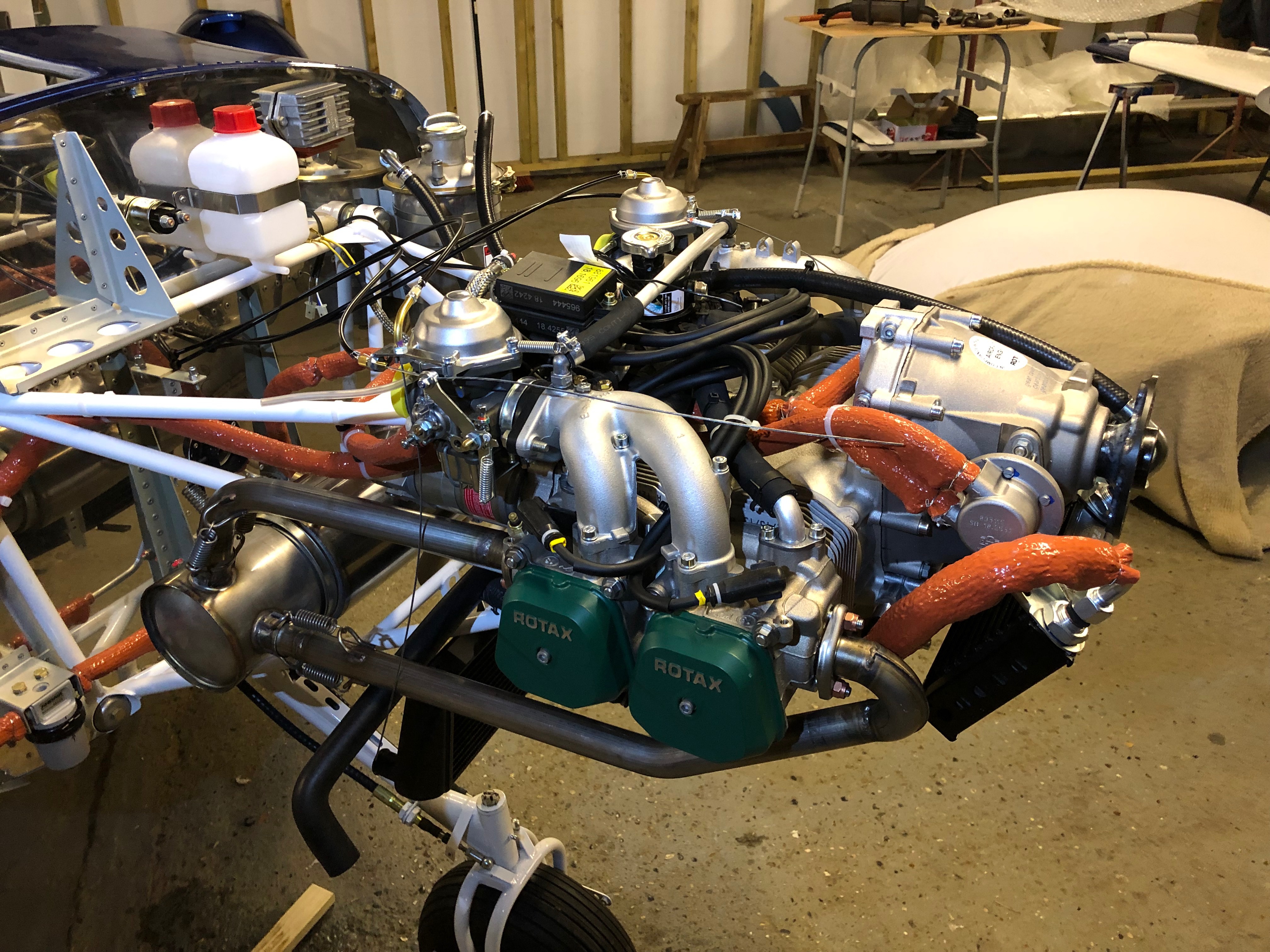
Today plan is to finish off some tasks that will see the completion of the oil system, exhaust system, NACA duct, and installing the rest of throttle cables ready for the throttle quadrant install.
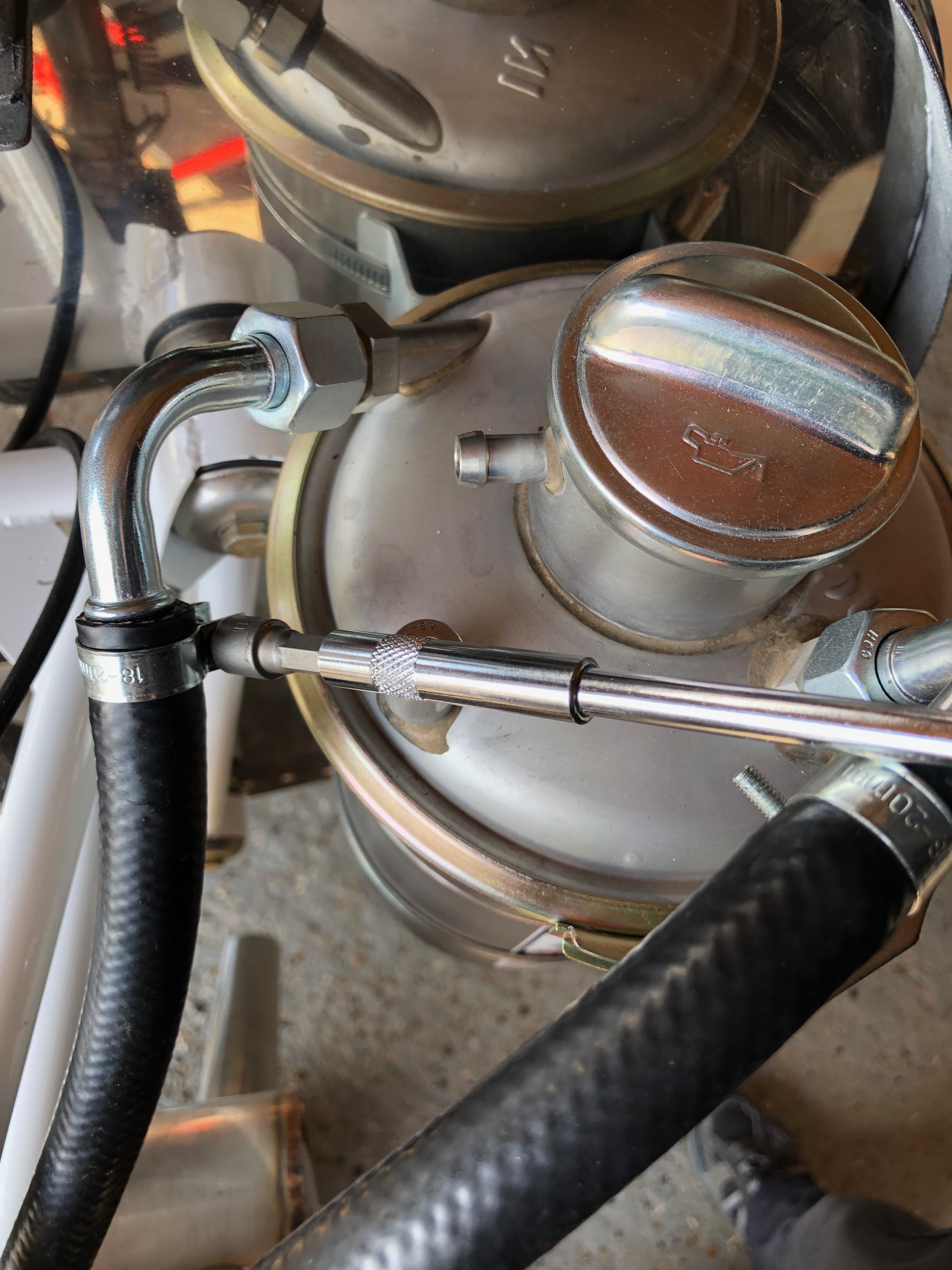
The hose clamp are added to the oil return line…
and the oil bottle. I’ve tried to position the clamps to make sure they are easier to get to for maintenance but out the way so someone working on in the engine bay won’t snag their hands or clothing on them.
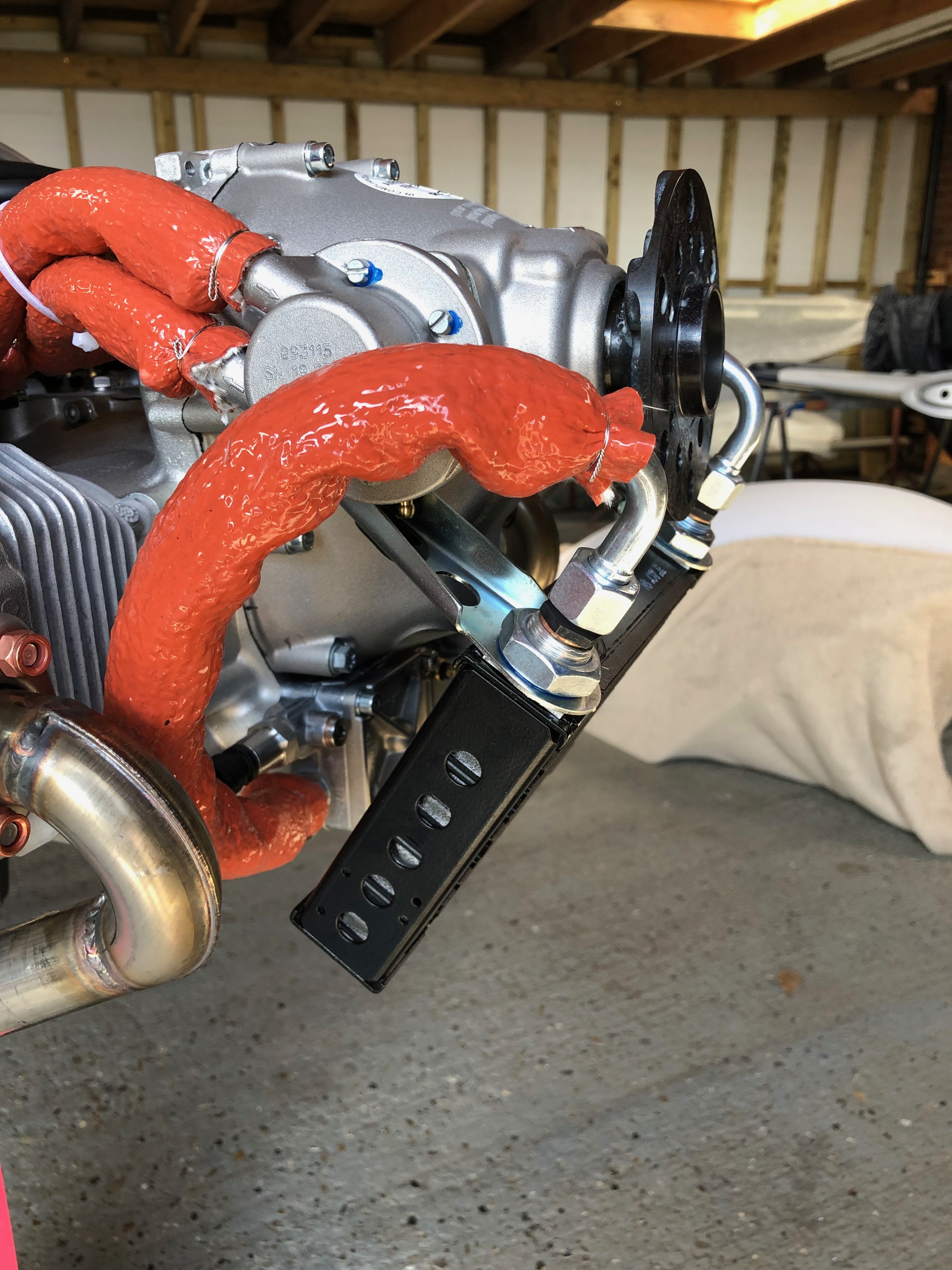
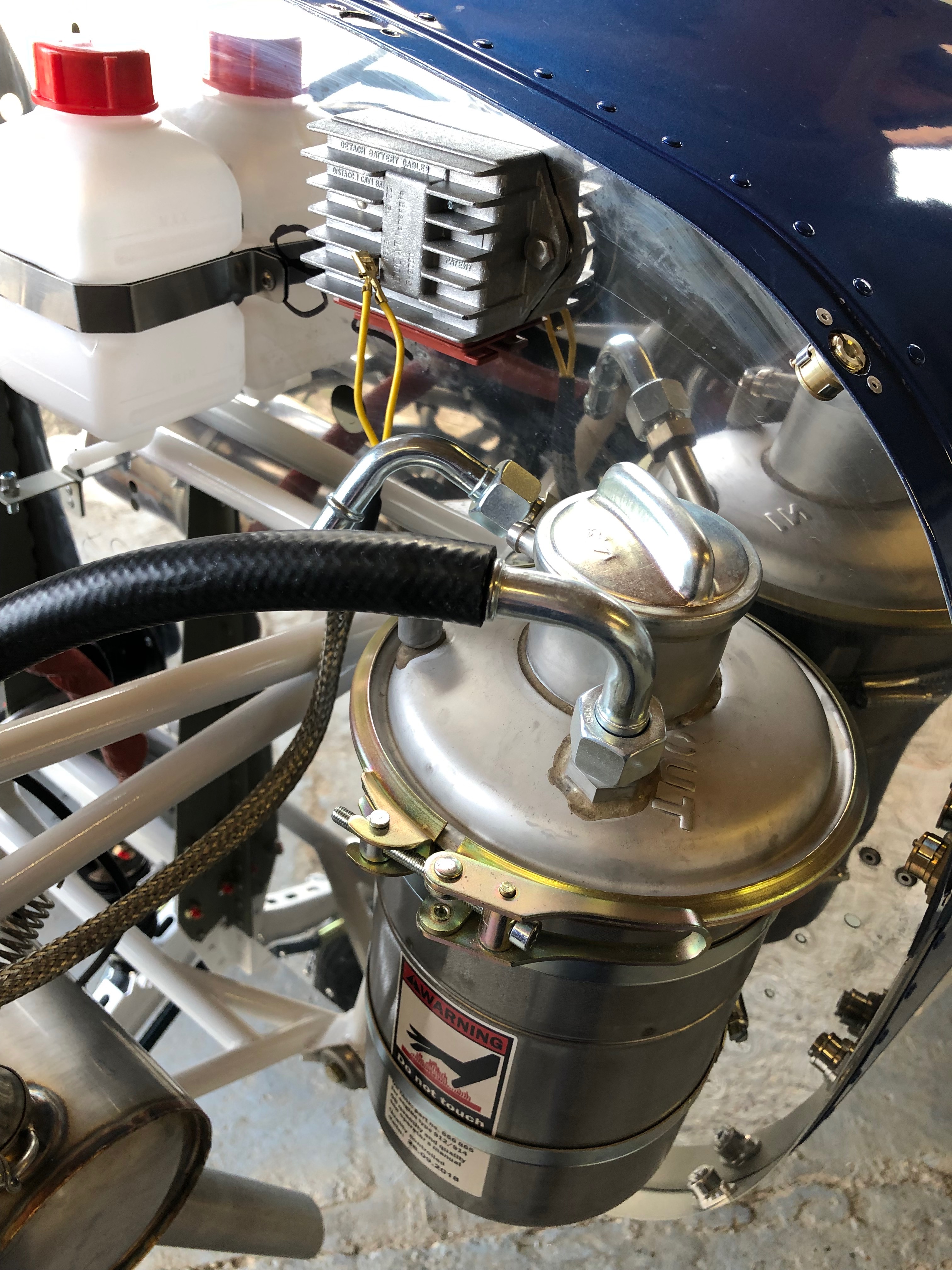
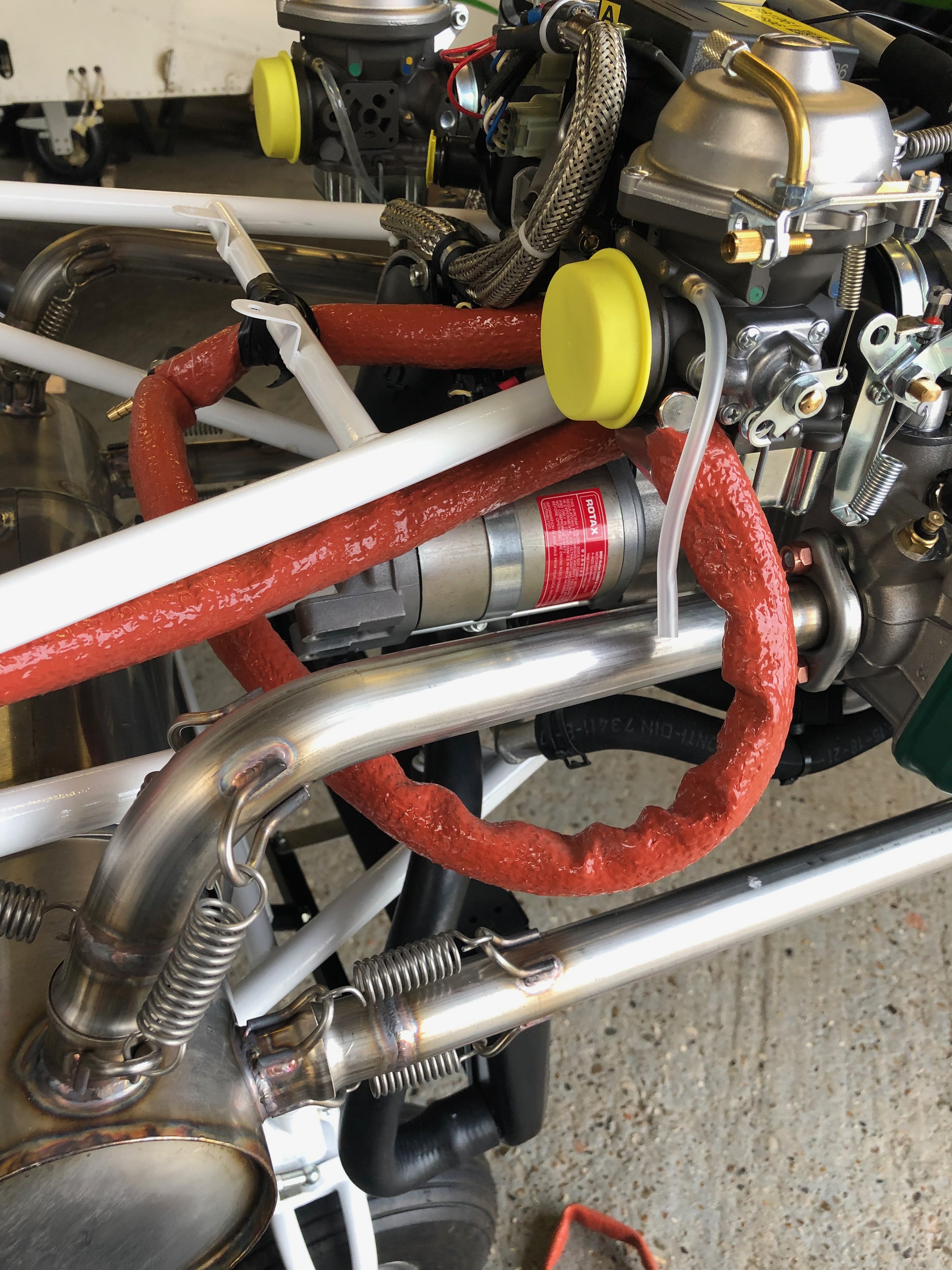
The oil pump to oil radiator pipe is clamped and fire sleeving is added as the pipe runs very close to the exhaust down pipe.
Fire sleeving should protect the oil hose but I will be adding some exhaust wrap to further protect the pipe. The oil system is now complete.
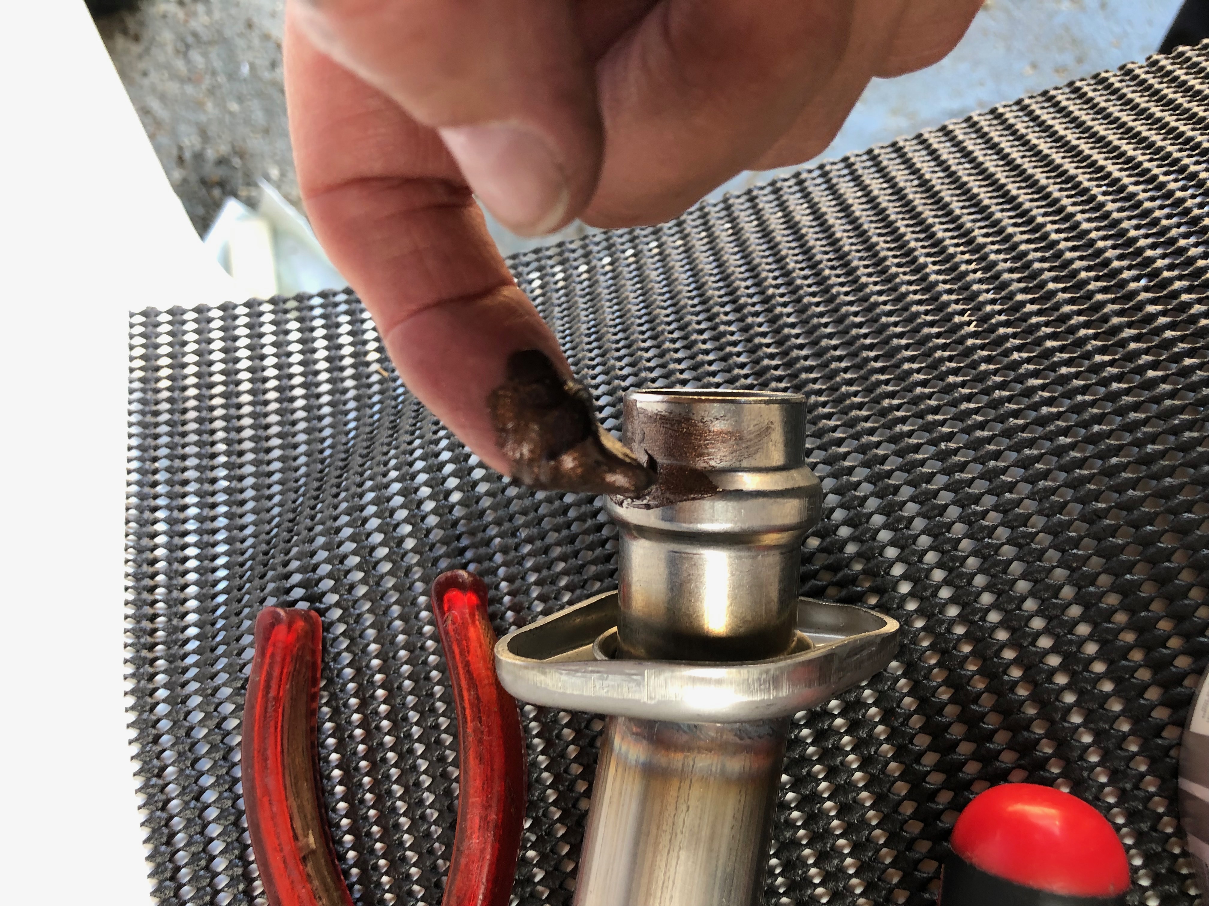
To finish the exhaust system install I need to apply some copper ease to the pipes to enable them to move slightly in service.
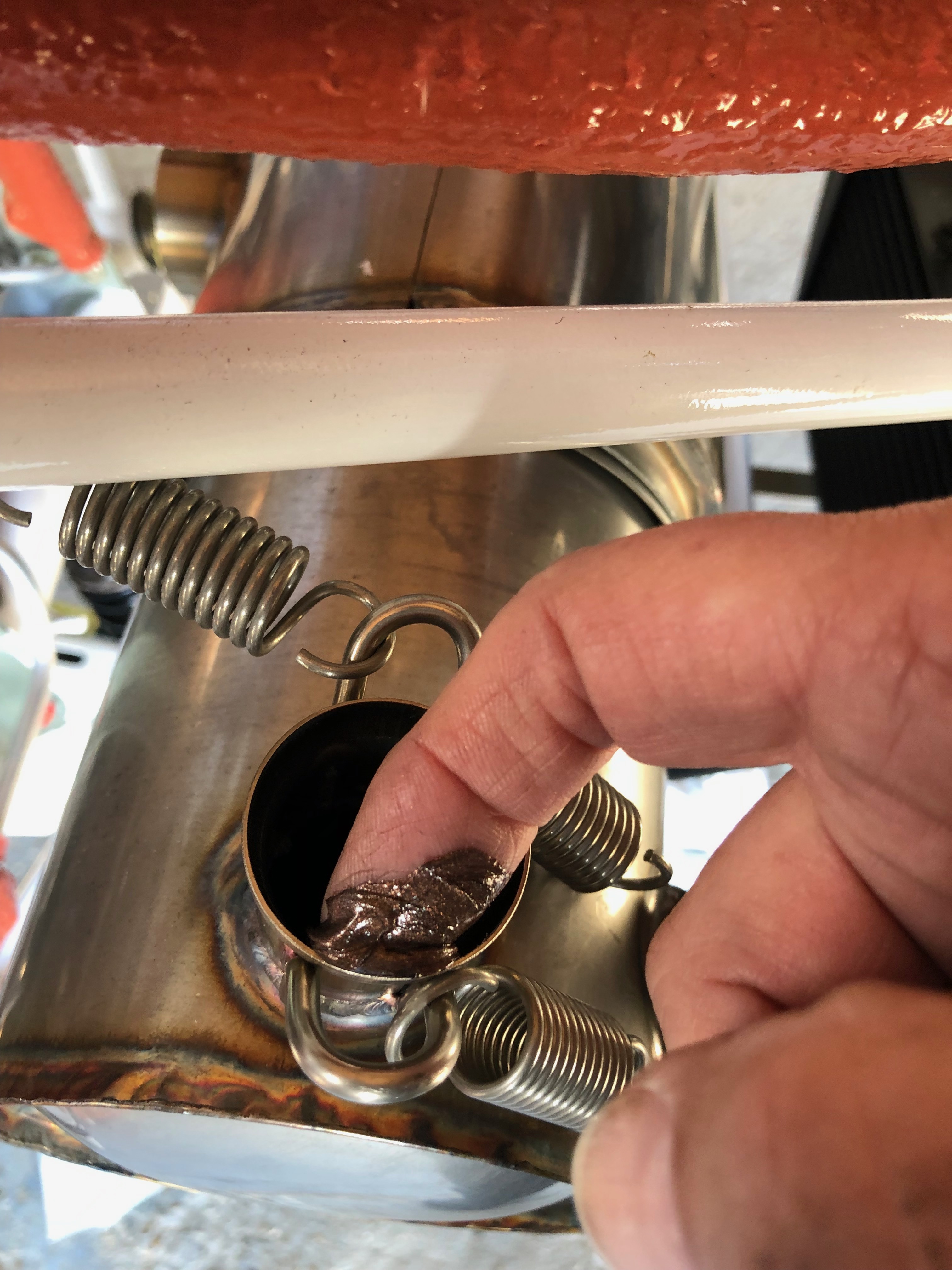
and also on the exhaust connection pipe.
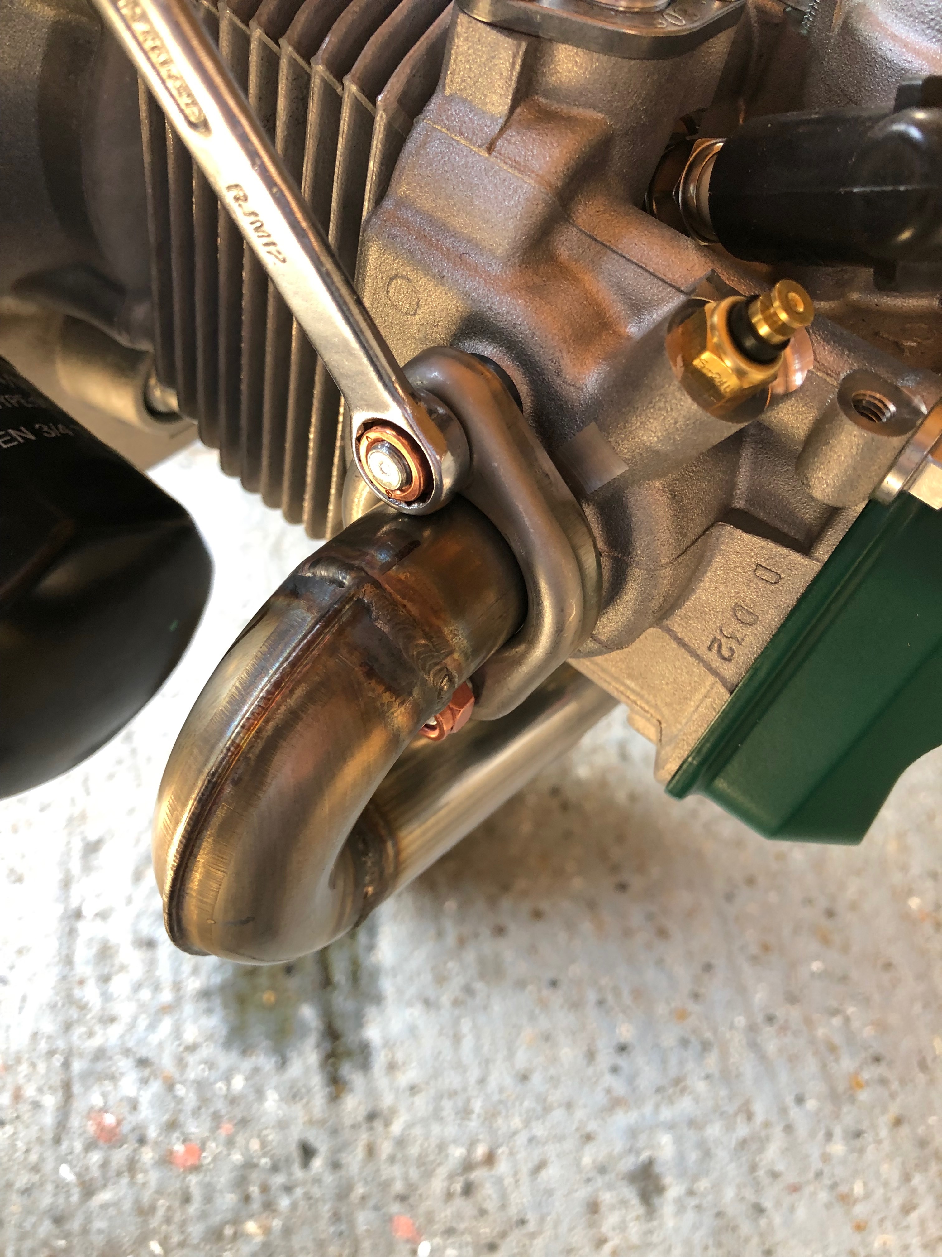
After checking the run of the pipes the nuts are tightened to complete the exhaust install.
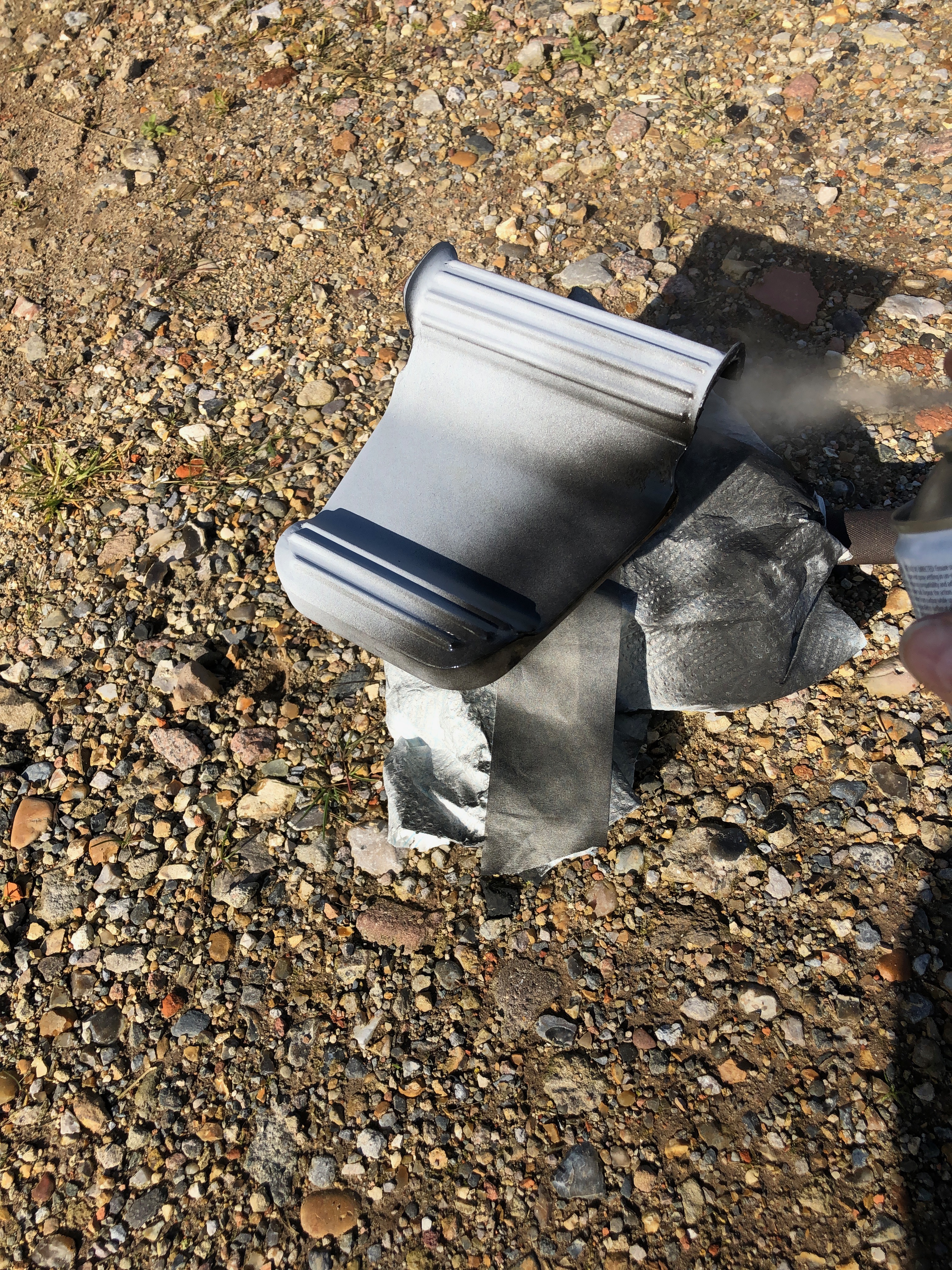
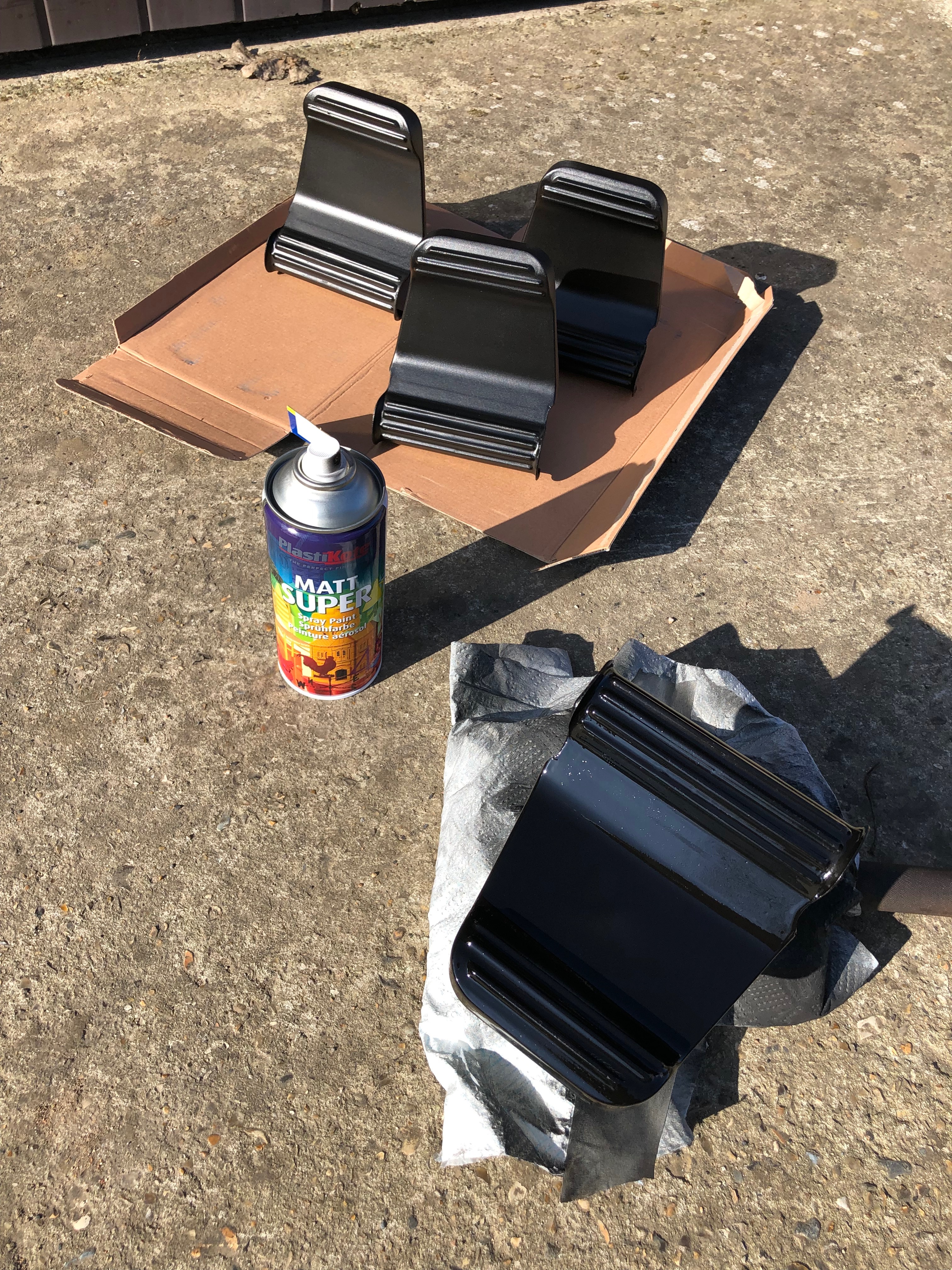
One of the jobs I can do between other jobs is to paint the rudder pedals. Two coats are needed leaving then to dry for about an hour between coats.
Last coat applied and drying off in the sun.
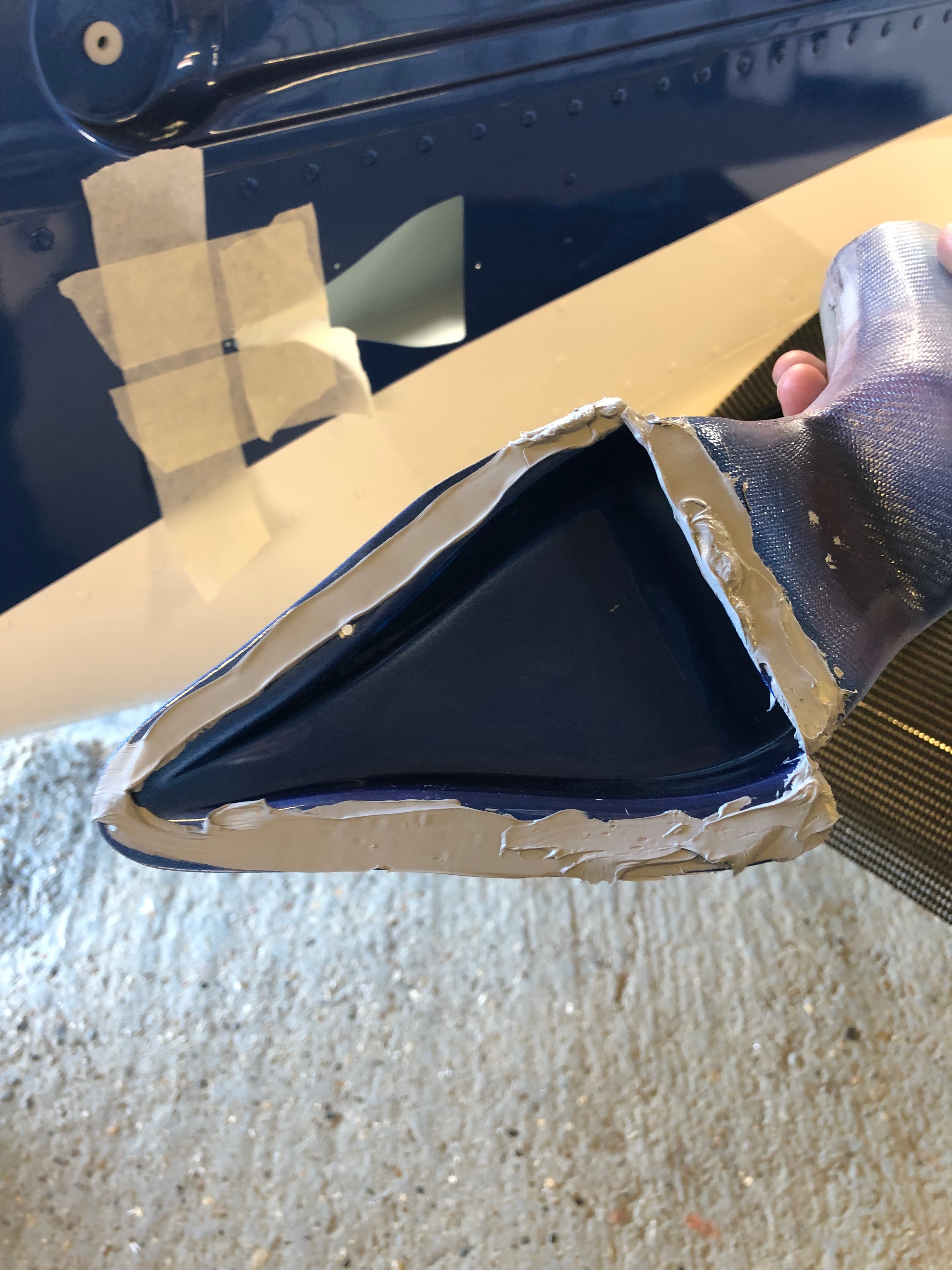
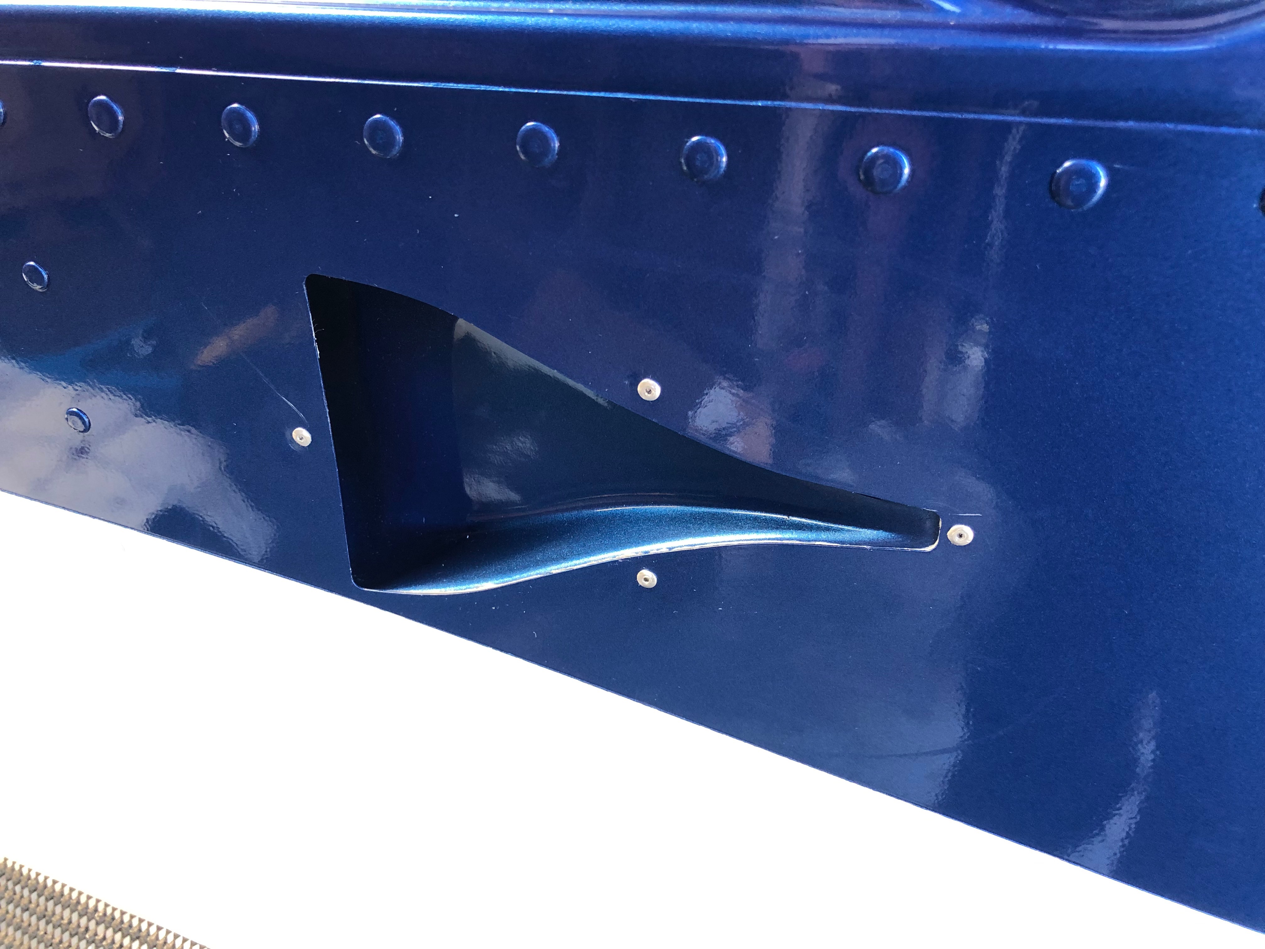
I had already drilled the NACA ducts but the mastic to seal them was too cold to apply so I had to warm it up slightly to apply it.
When I riveted the right side NACA duct I slipped twice and scratched the paintwork slightly which will need touching up and polishing out at some point. To stop this happening again I applied some asking tape around the rivet.
Right side duct. As you can see a slight scratch on the left rivet.
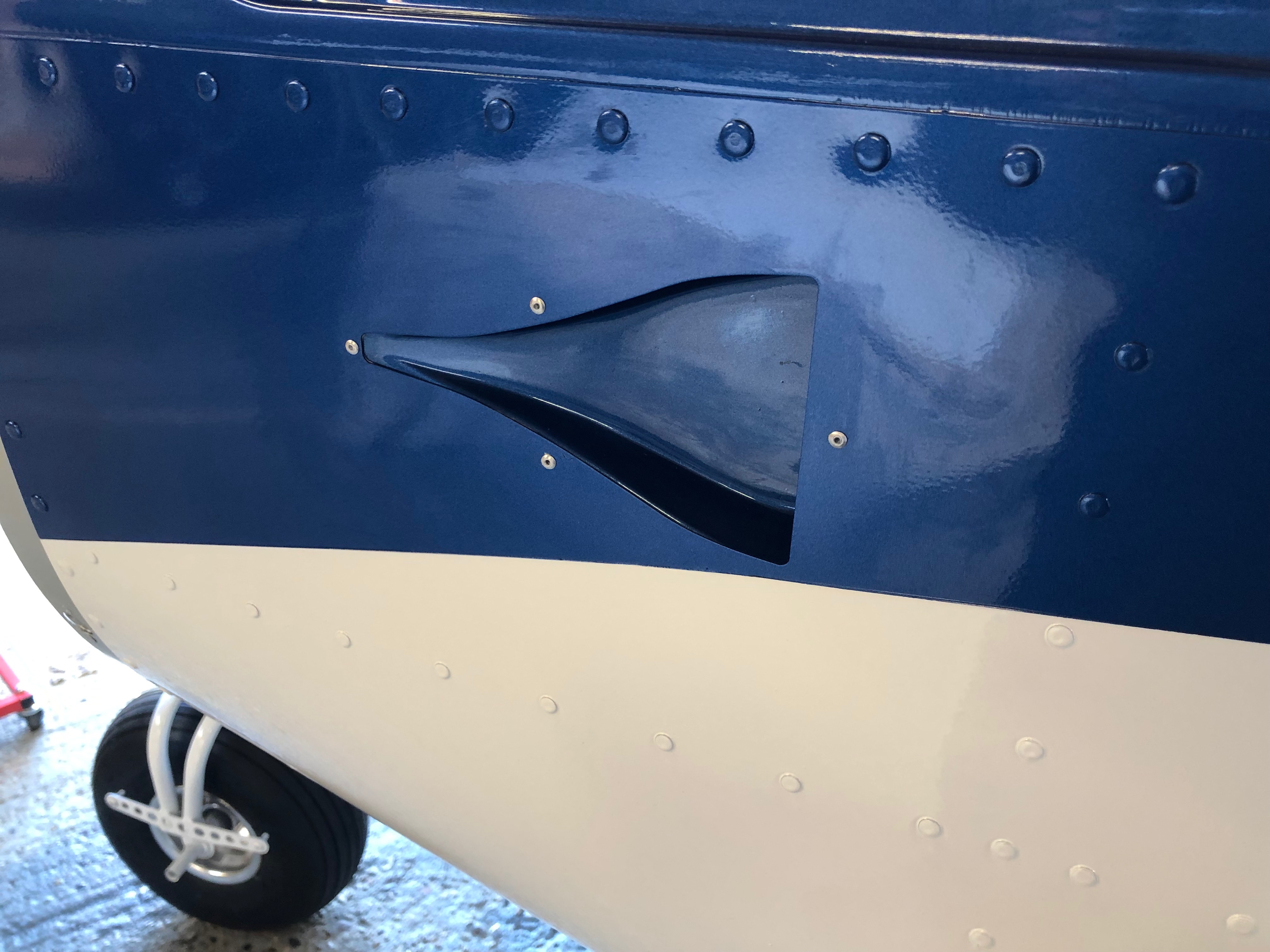
and the lefthand duct. A better job on this side. The duct install is now complete but still needs the Scat hose to be added for the cabin air vents.
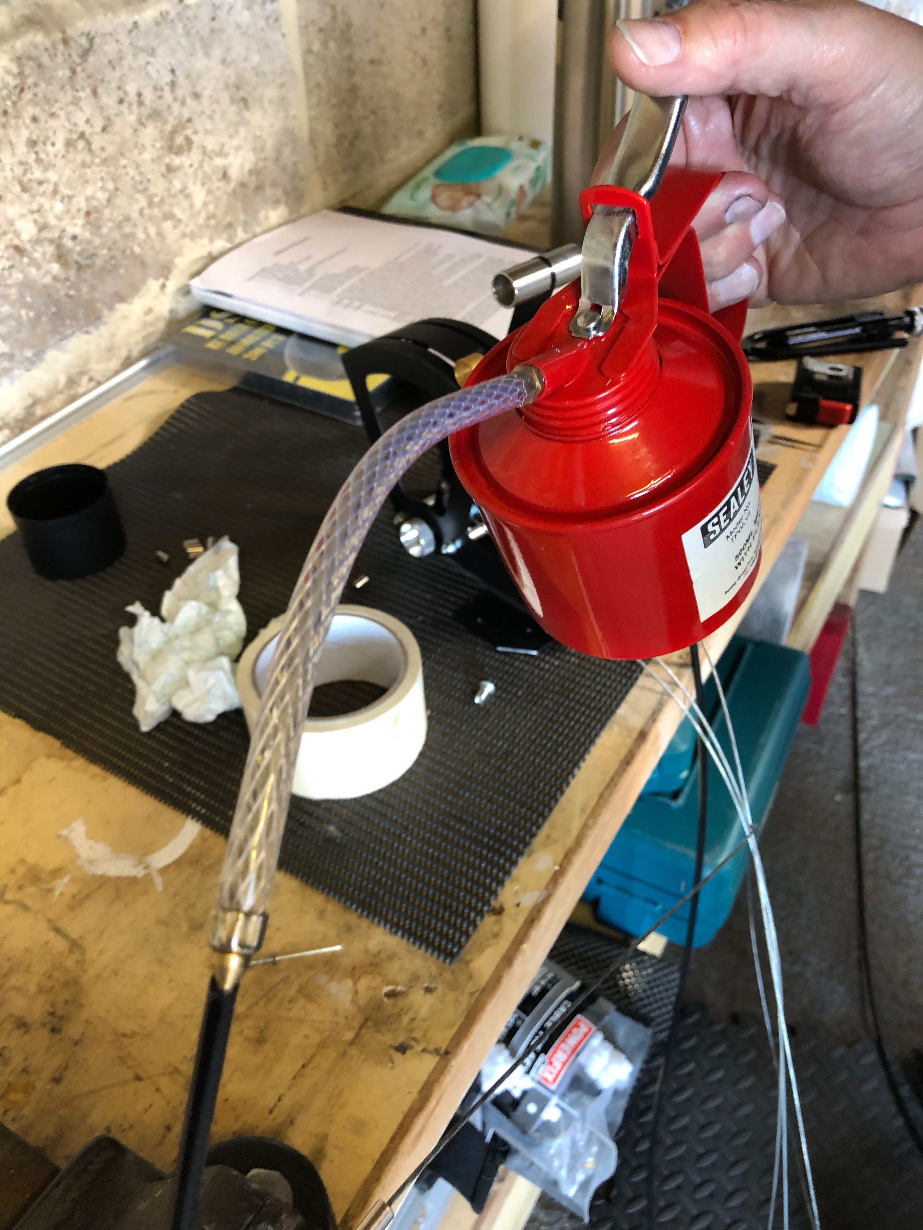
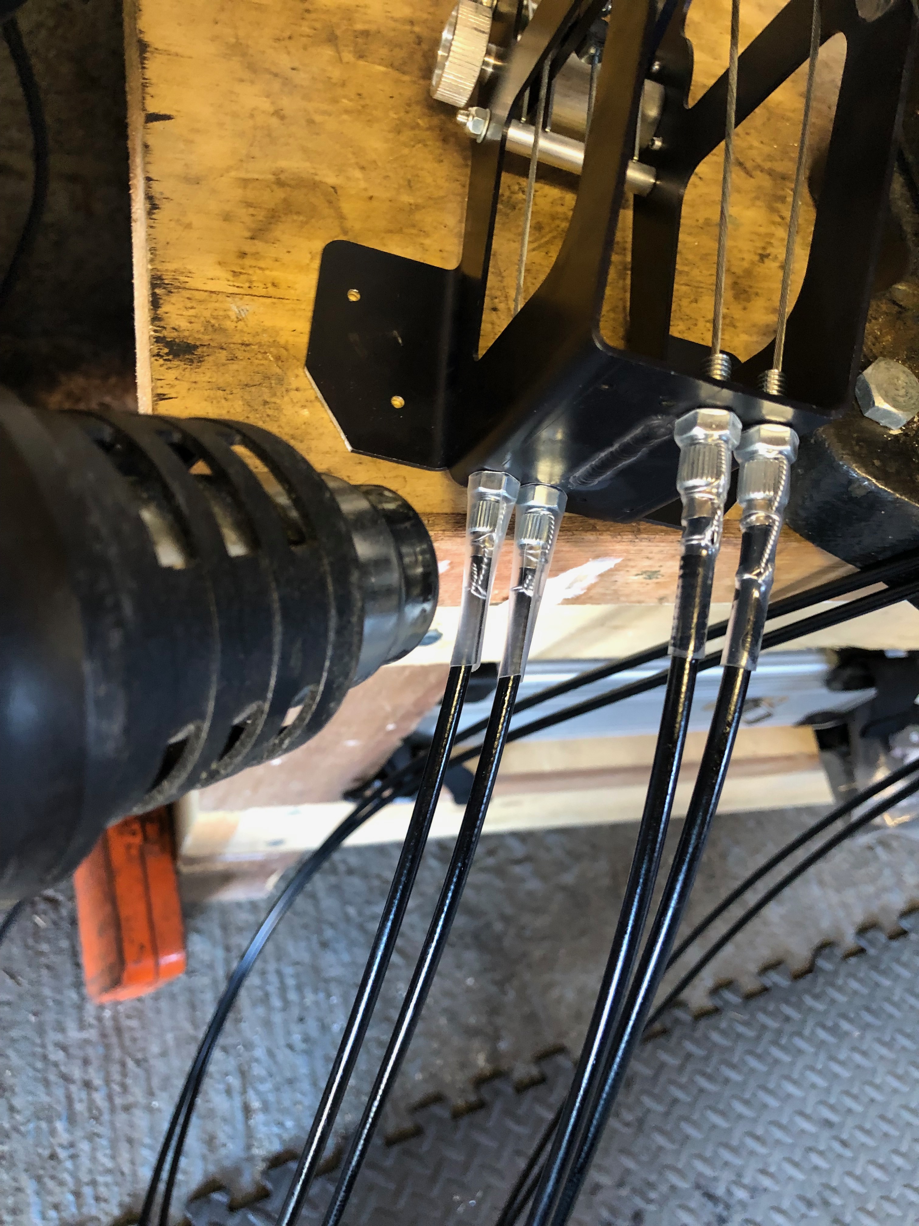
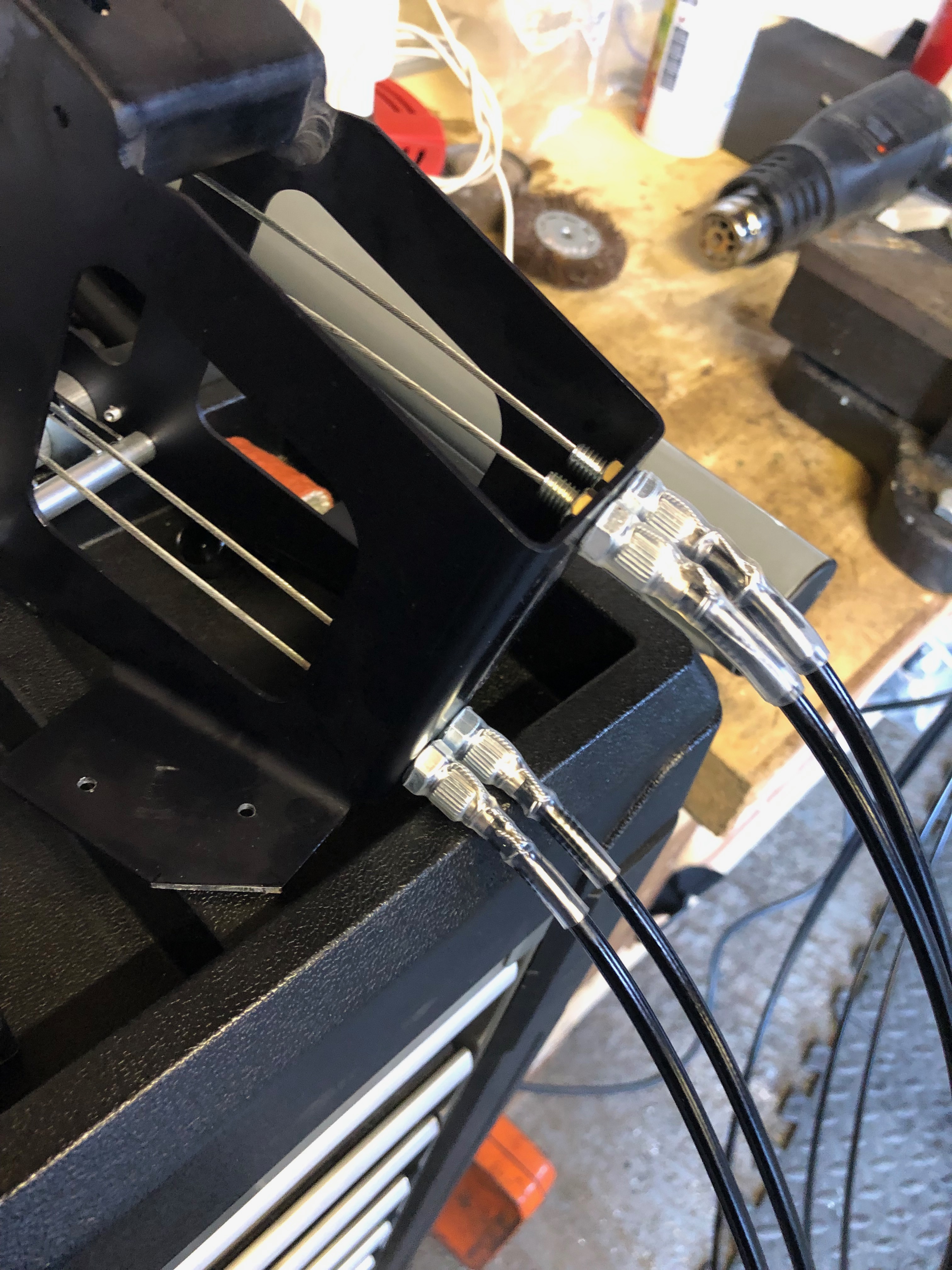
The throttle cables have to be cut and made up. A few drops of oil down the outer will allow the cable to run smoothly and operate better in service.
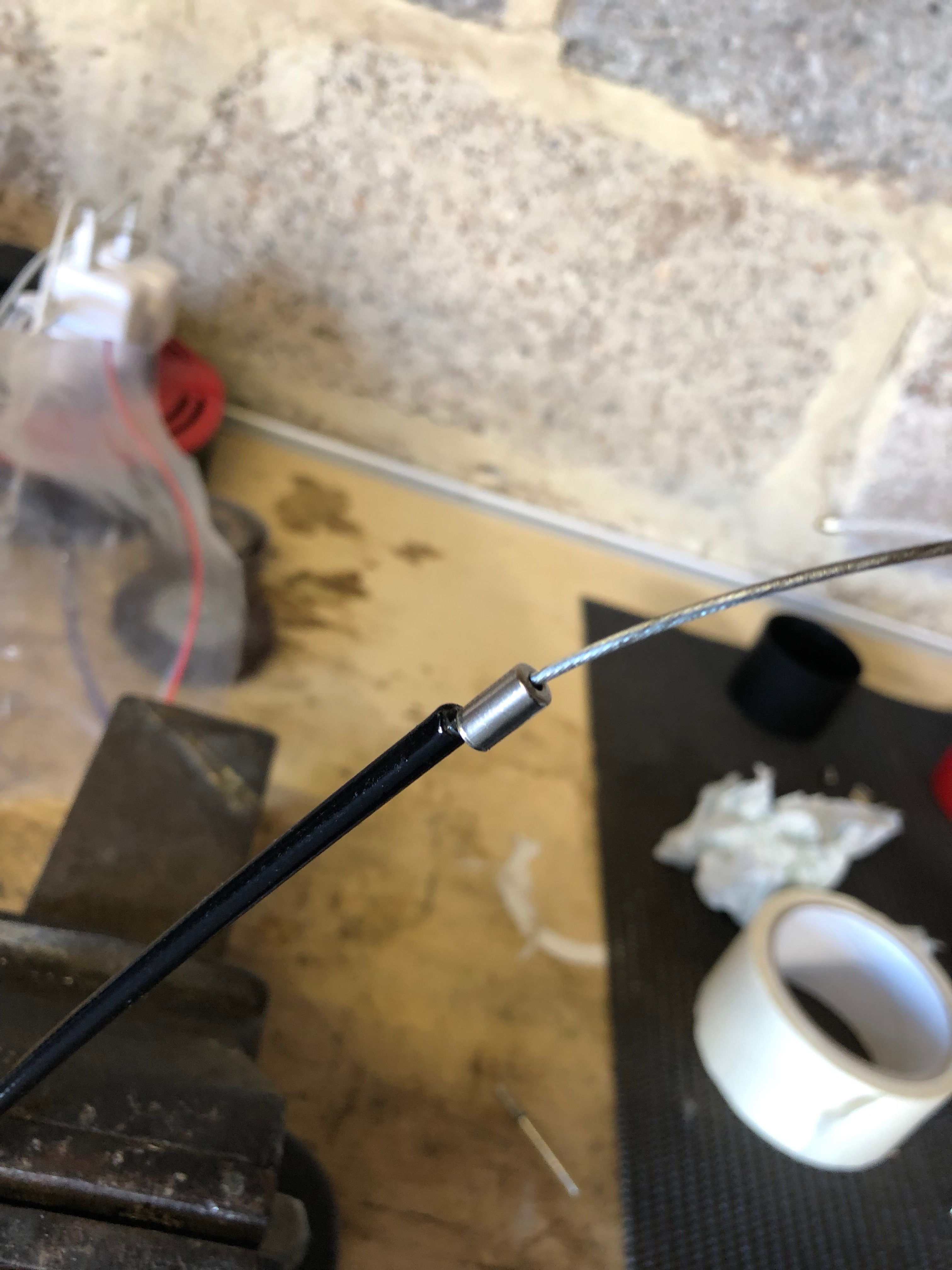
Ferrules are added to the outers before fitting.
Wire locking is added and a piece of heat shrink tubing is slipped over the assembly to ensure is doesn’t undo.
The throttle quadrant is complete and will be installed when I come back this evening.
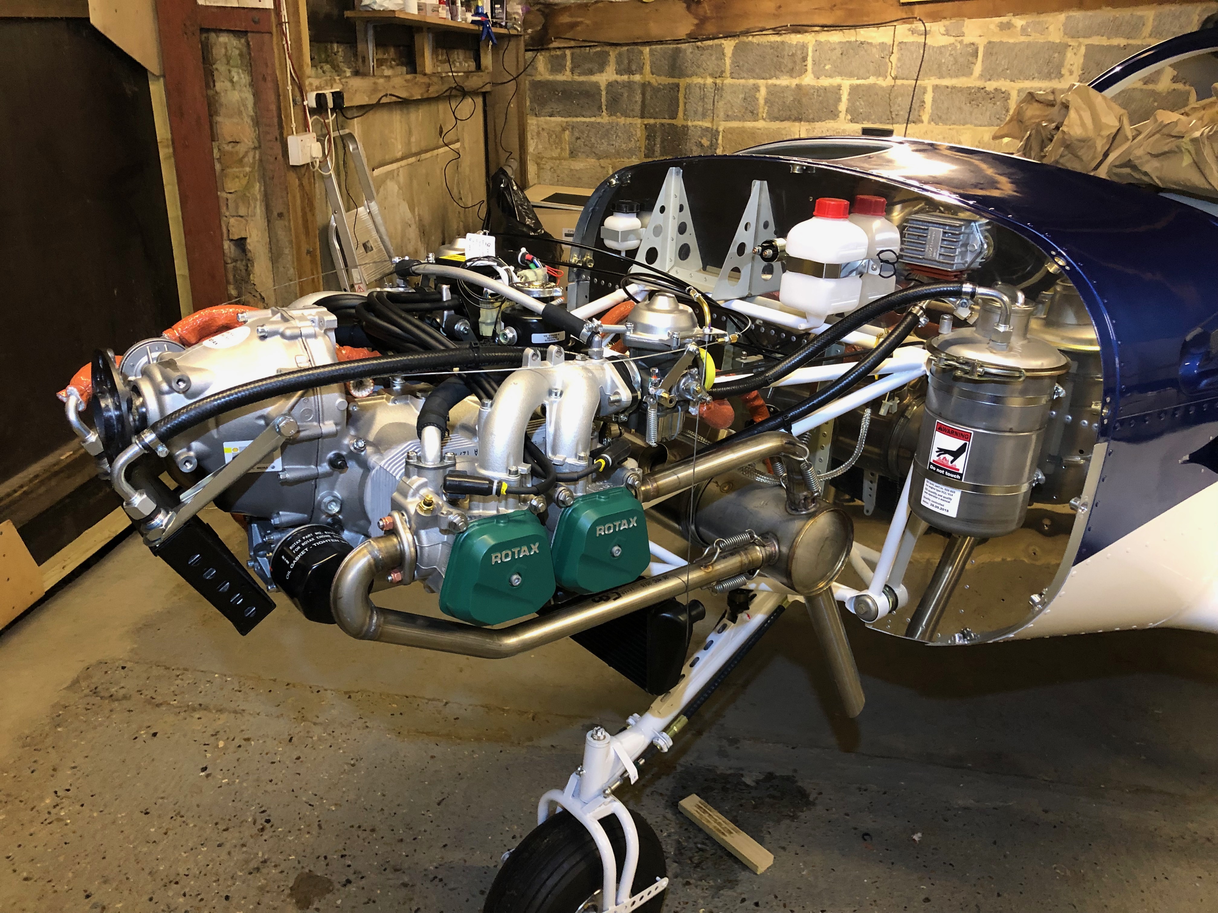
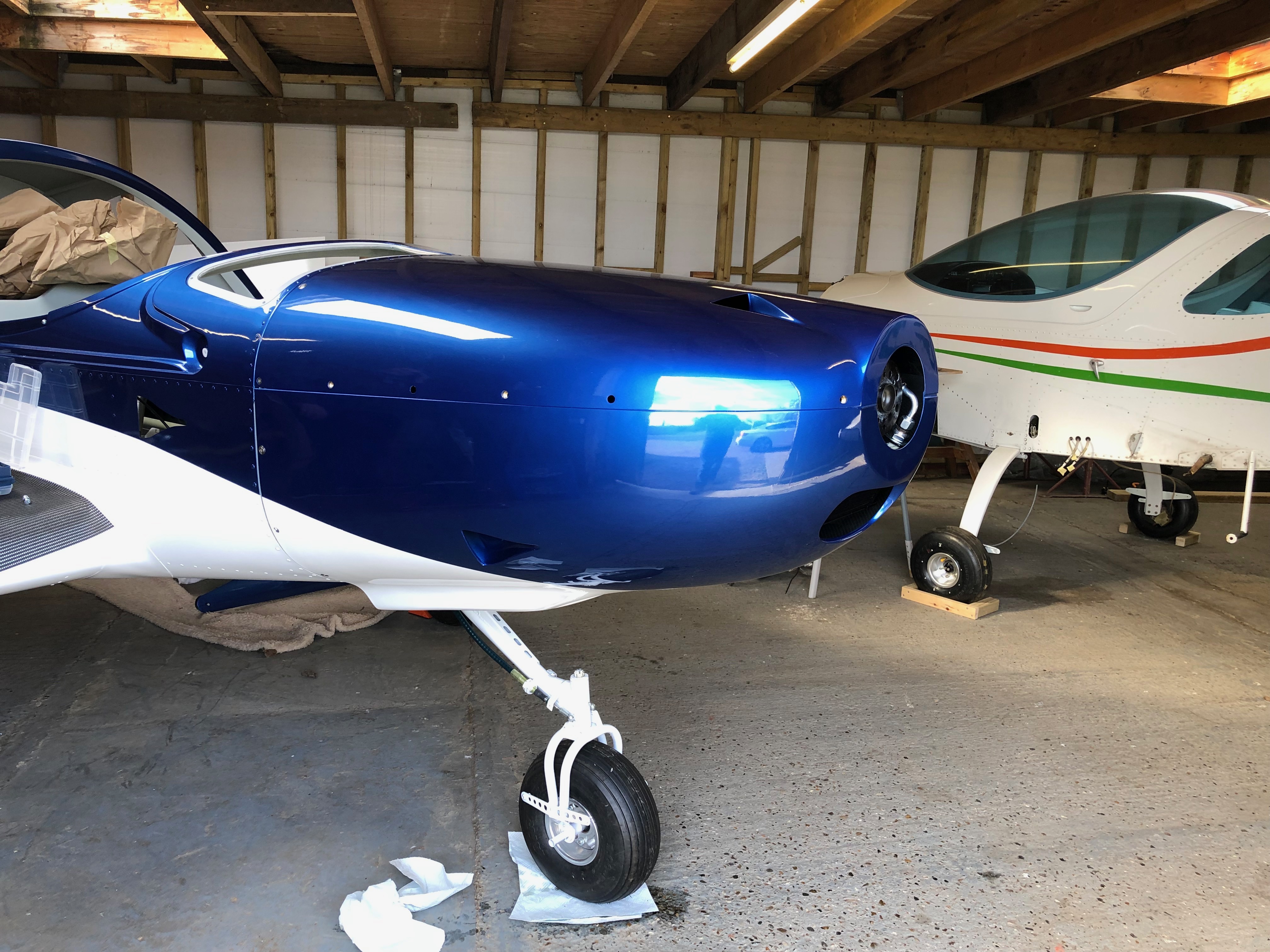
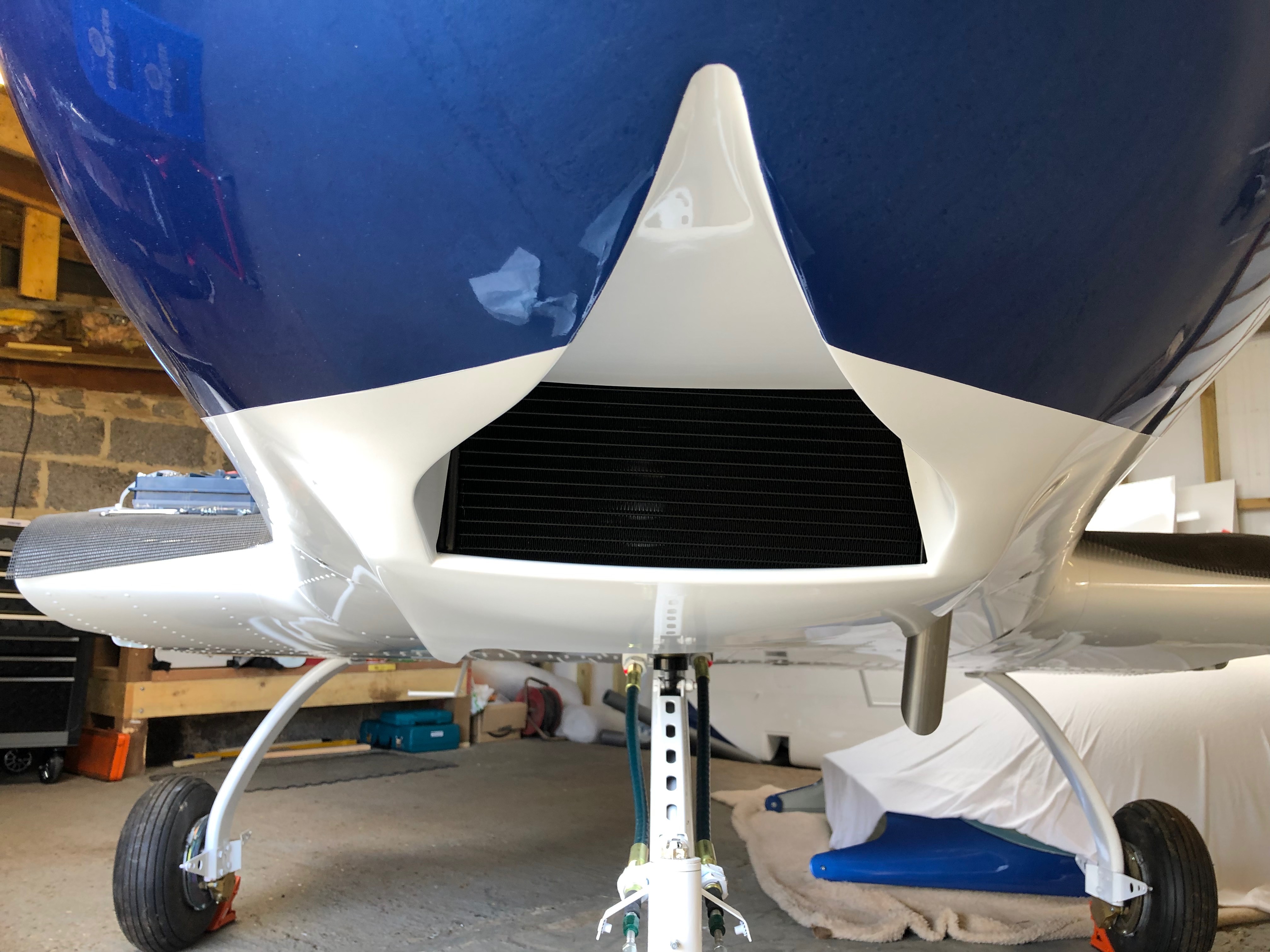
After fitting the fuel, oil and hose systems it’s time to see if the cowls fit properly around the radiators. It’s a two person job so Karen has come to help me this morning.
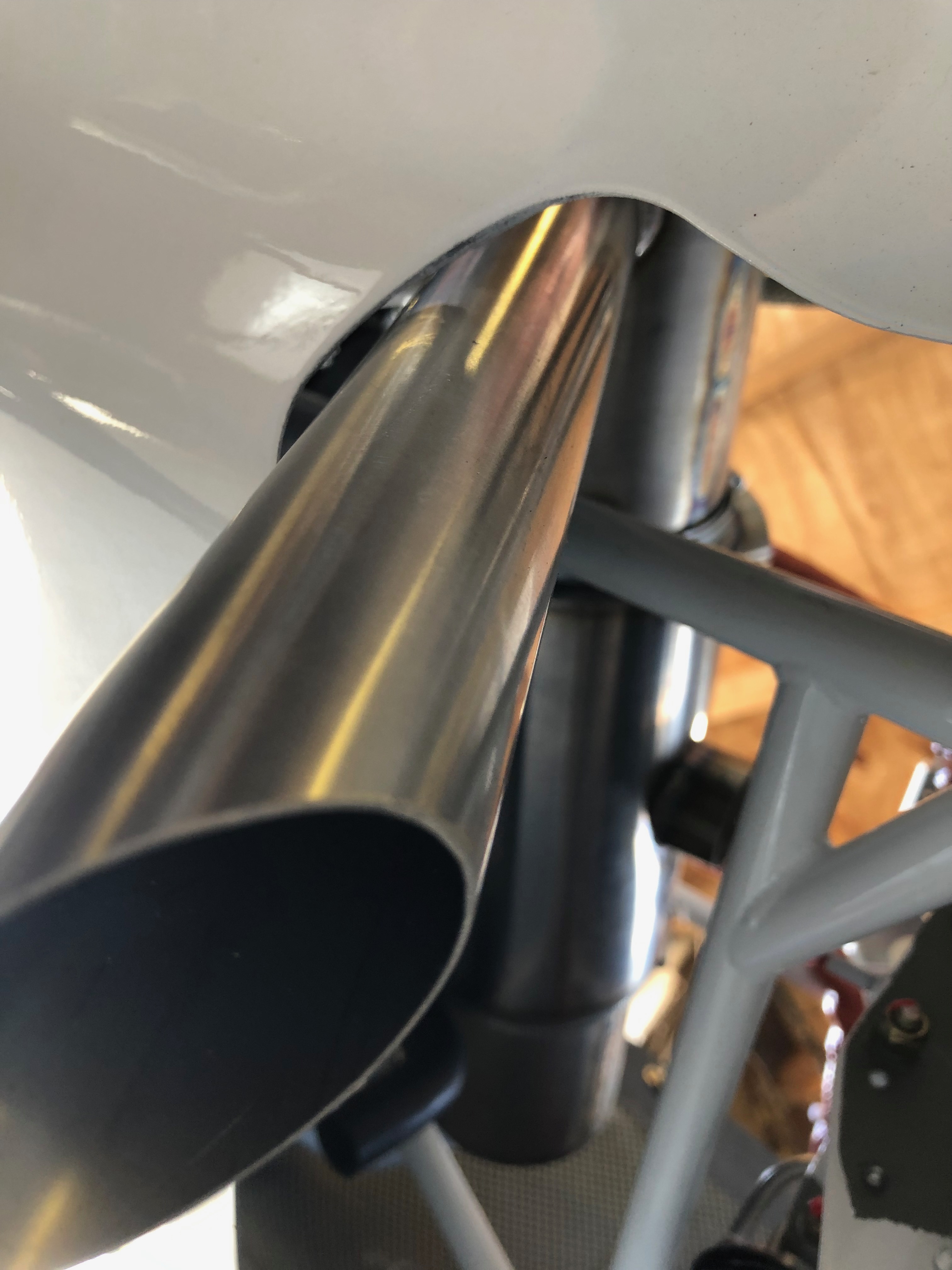
Exhaust pipe is very close but the clearance should be ok.
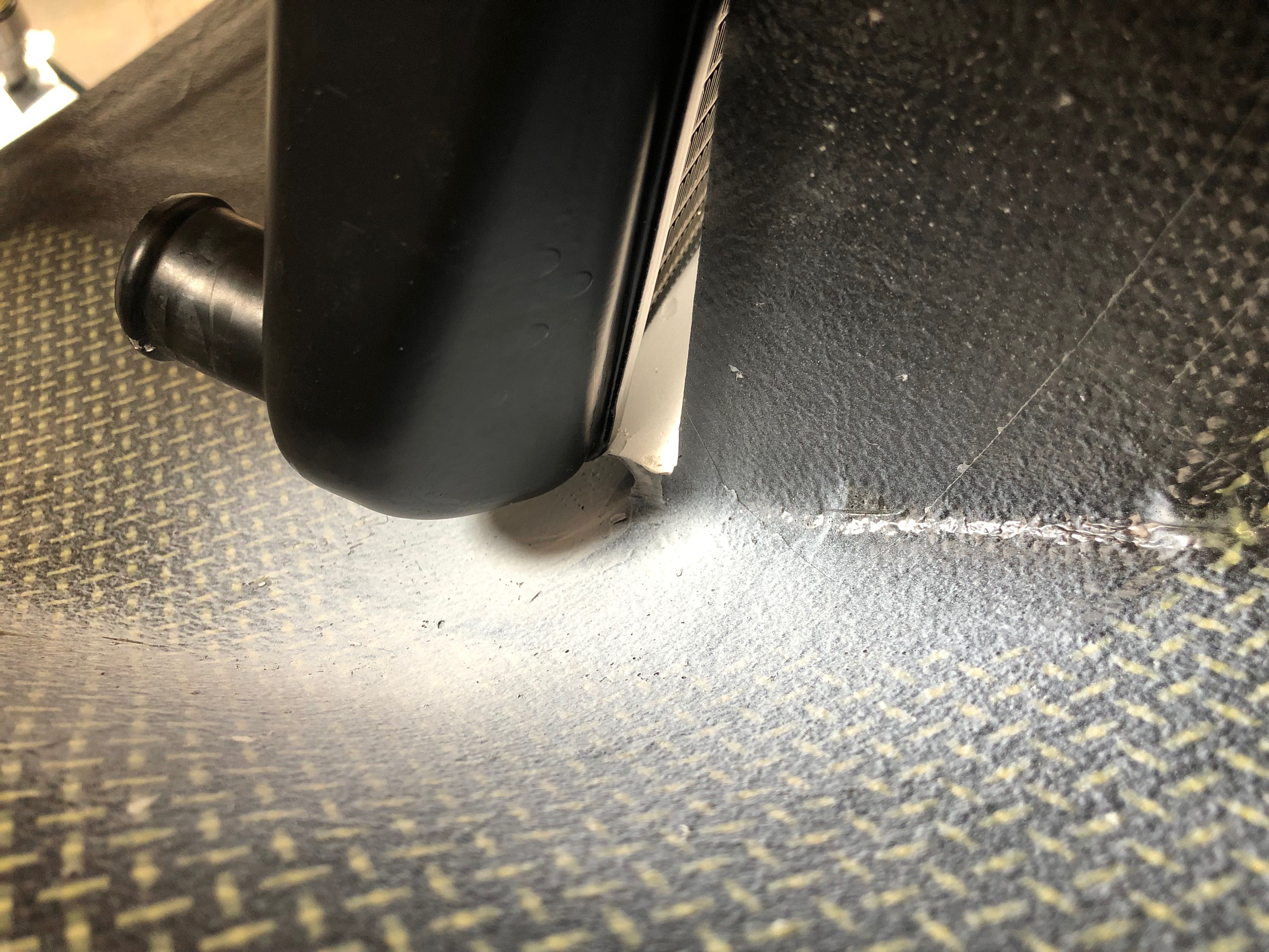
However the water radiator is too tight so the position and cowl will need to altered.
I will need to drill a hole for the fuel drain so I can check the fuel before each flight.
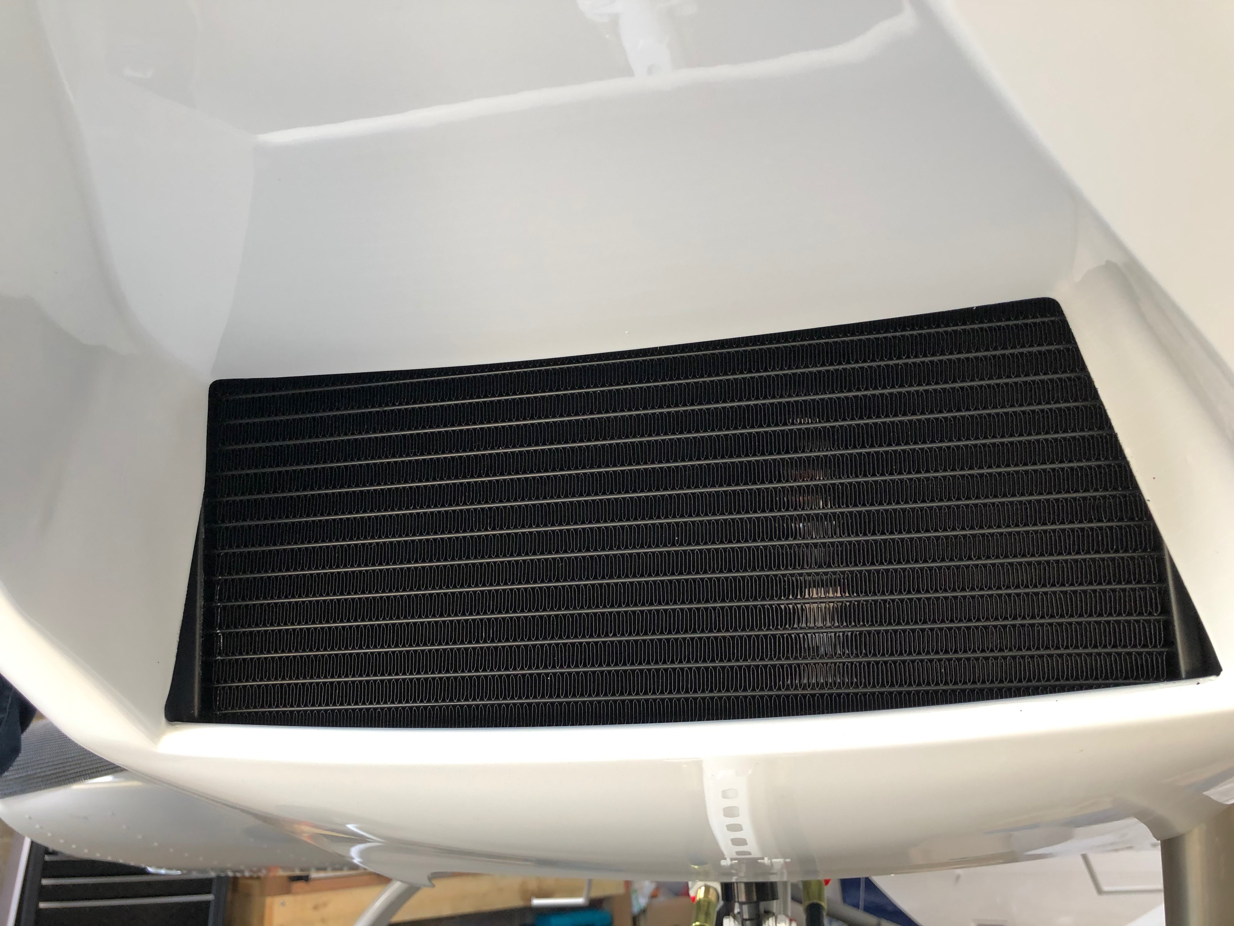
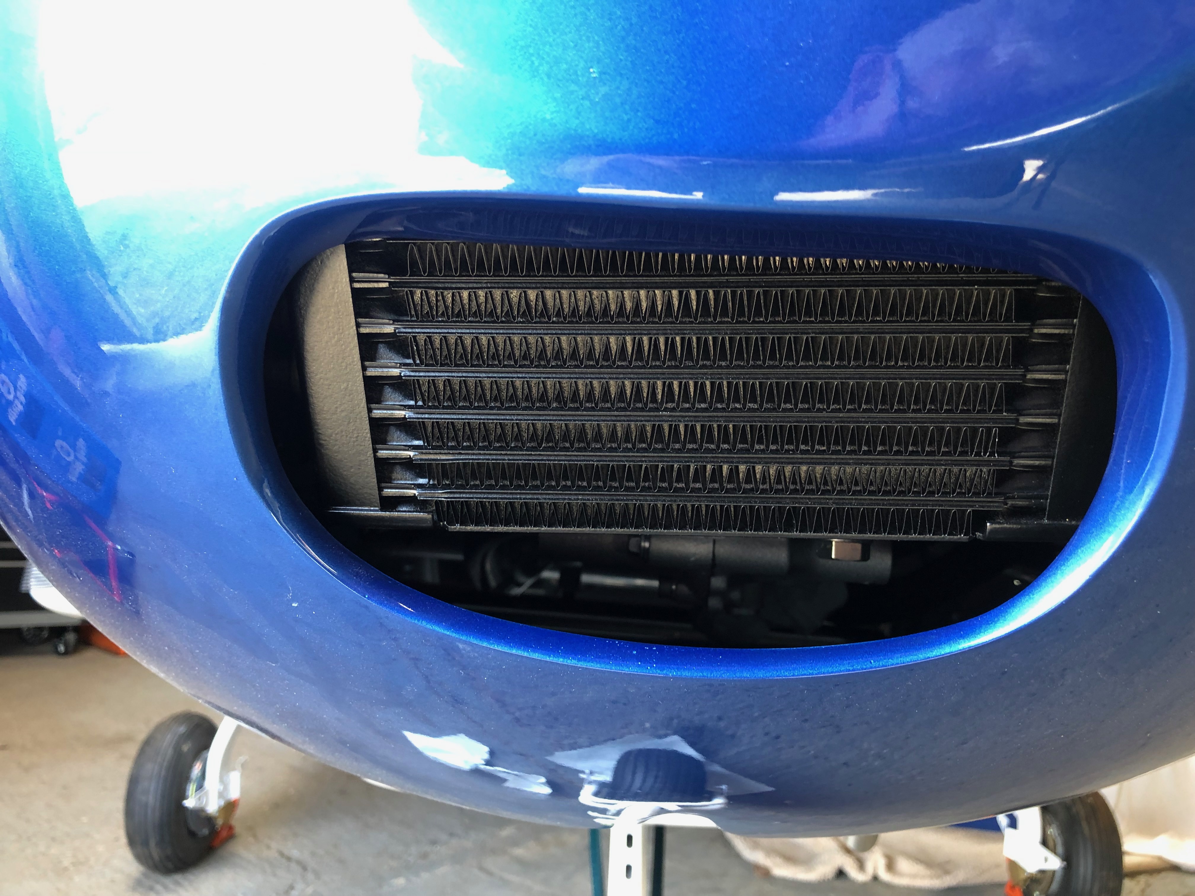
From the front the water radiator looks fine.
From the rear, the radiator brackets disconnected to allow movement for the trial fit.
The cowls fit but again only with the radiator brackets disconnected
Underneath looks fine.
The oil radiator fits fine with a slight adjustment to its position.
All seems to be centrally located.
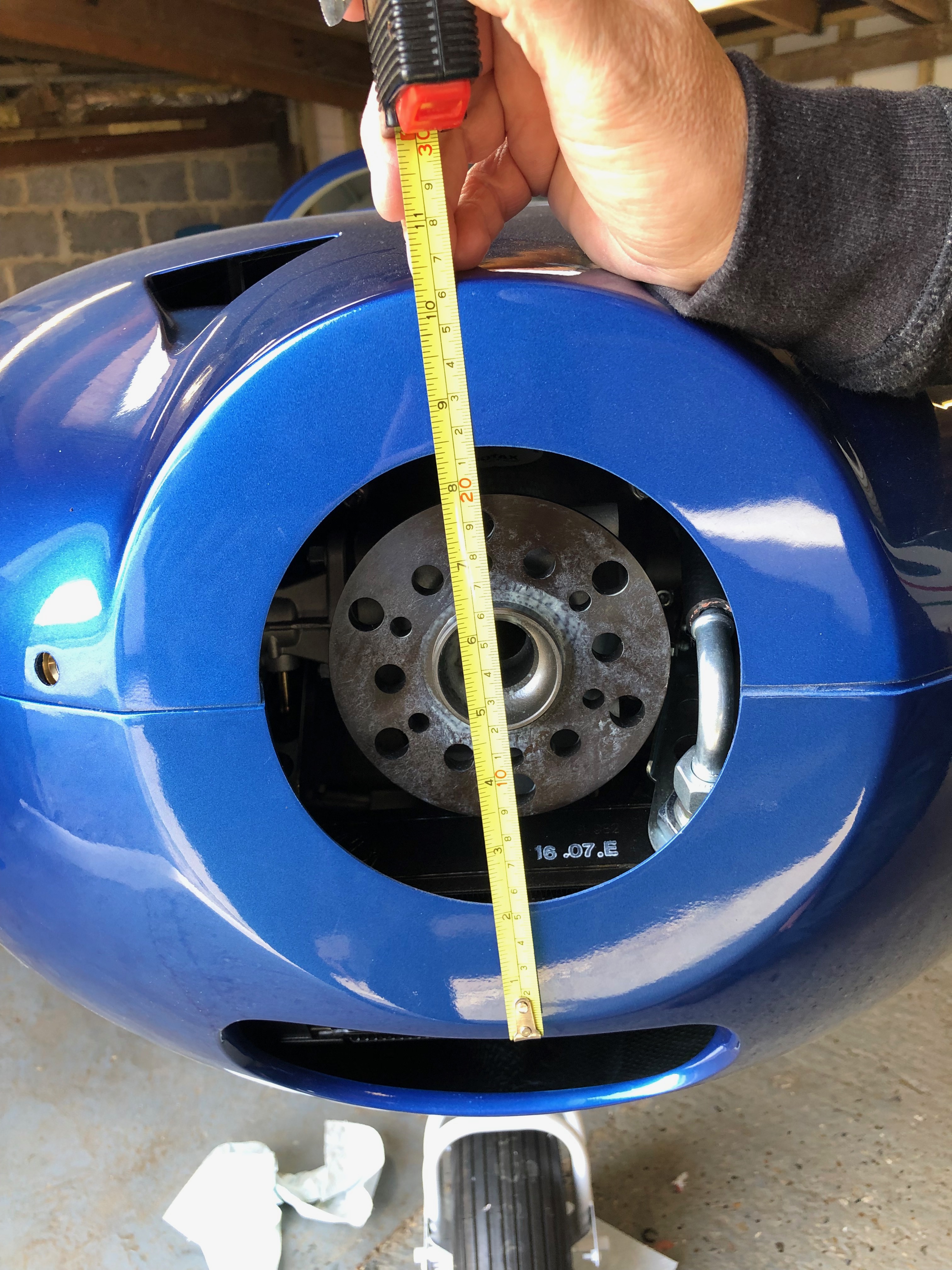
Need to measure the front of the cowl for the spinner size.
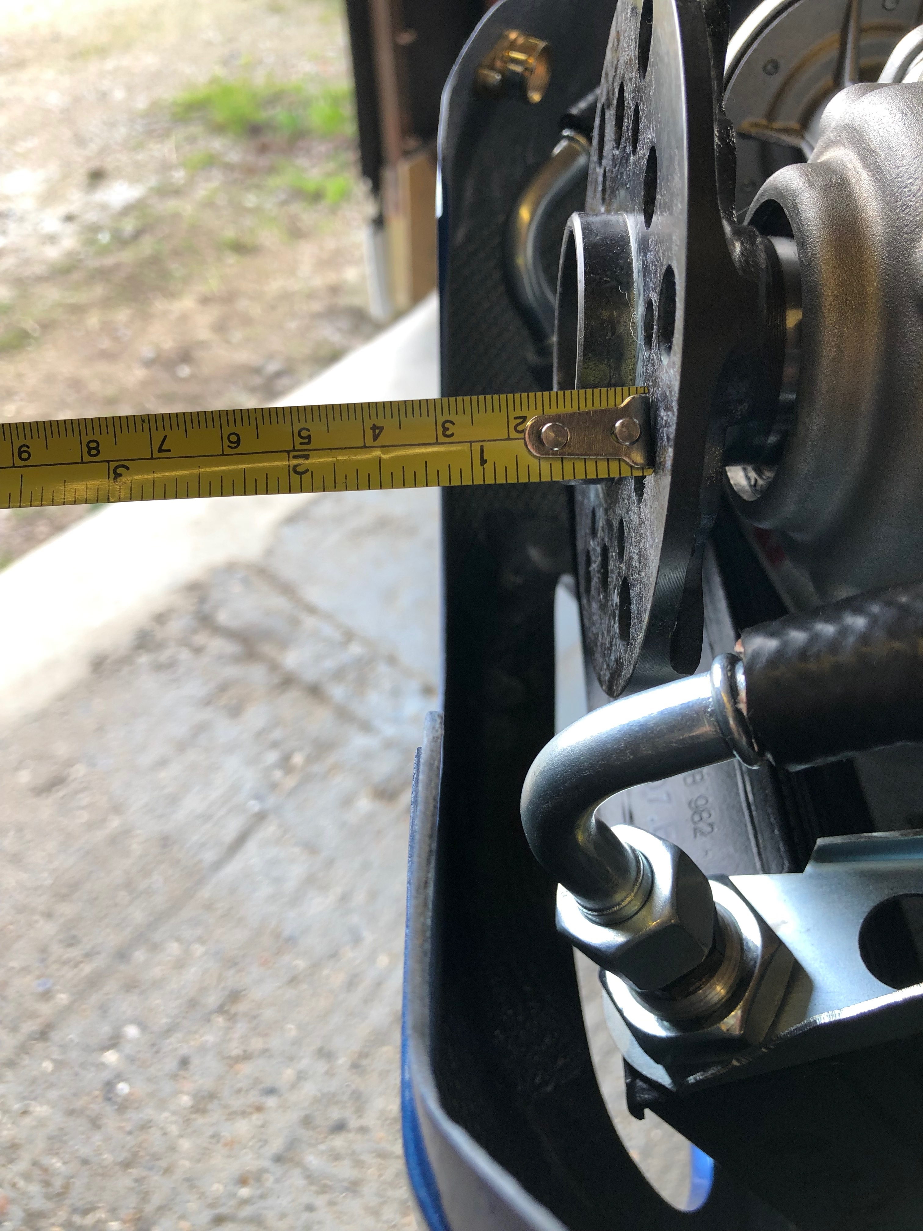
And the distance from the engine flange plate to the cowl. This allows a calculation to be done for the prop extension that needs to be fitted.
The fuel pipes each need to be bent 45 degrees to accept the connection pipes from the fuel selector.
I had a number of things planned to do tonight which included installing the reducing connector on the return line, bending the fuel pipes in the cockpit to accept the pipes from the fuel selector, applying Loctite to the oil radiator bracket and mount bolts and fitting the NACA air ducts.
First up is bend the fuel pipes using a pipe bender. Got to be careful that I don’t bend the pipes too far as it’ll be virtually impossible to bend them back. Luckily it has an angle guide to help.
All three pipes now bent as required. It was easier than I expected apart from the pipe on the right which was impeded by the adjacent bracket.
Onto the the fuel return line. First job is to cut the pipe and insert the reducer.
The return line is 6mm i.d. so the reducer converts from 6mm to 8mm so it can be connected to the 8mm aluminium return line.
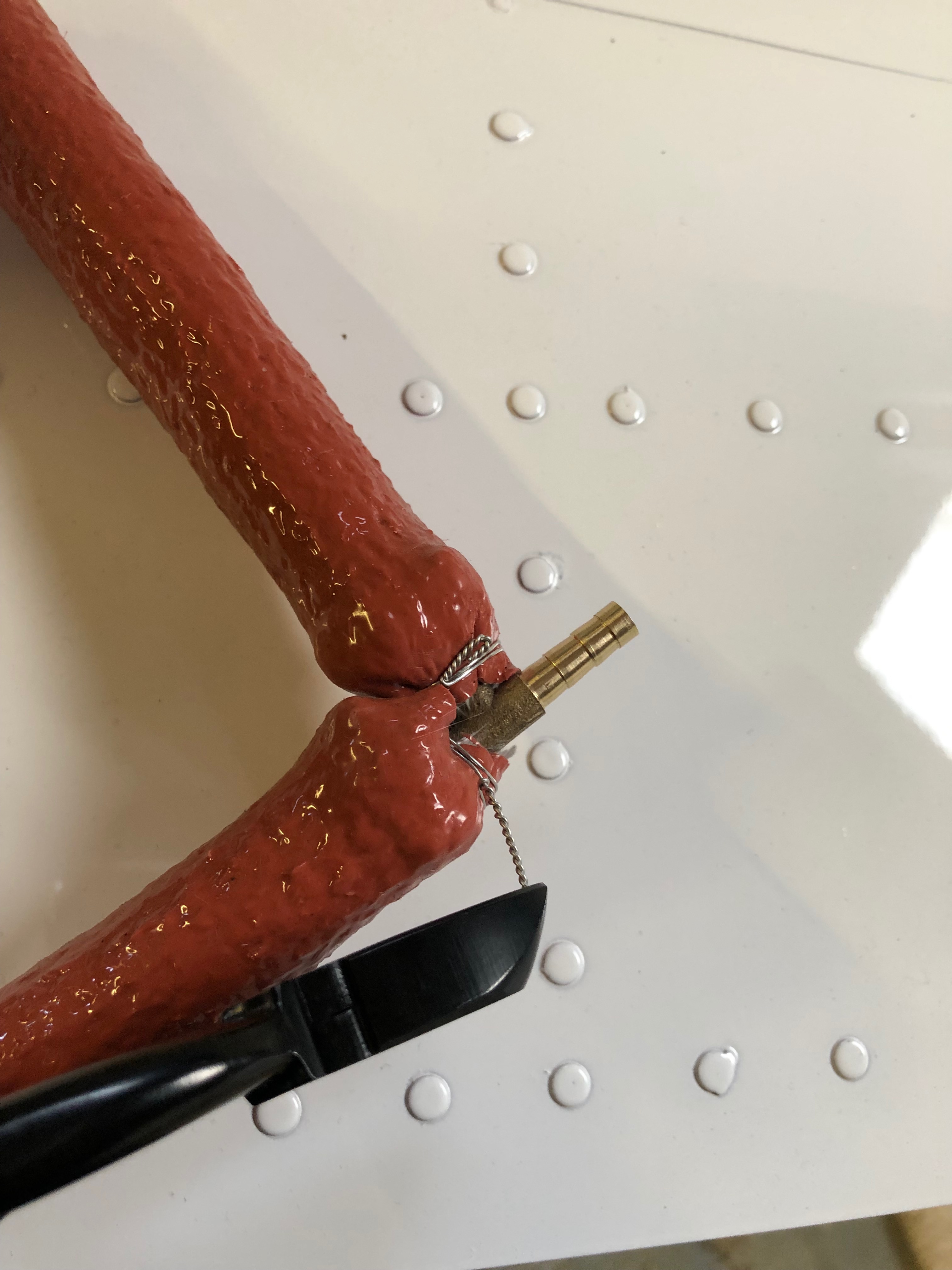
Clamps and a new section of fire sleeving is slid over the pipe and wire locked together and at the end.
Loctite 243 is applied to the oil radiator threads and the bolts are tightened immediately.
Loctite is also added to the threads of the oil radiator bolts that hold it to the engine.
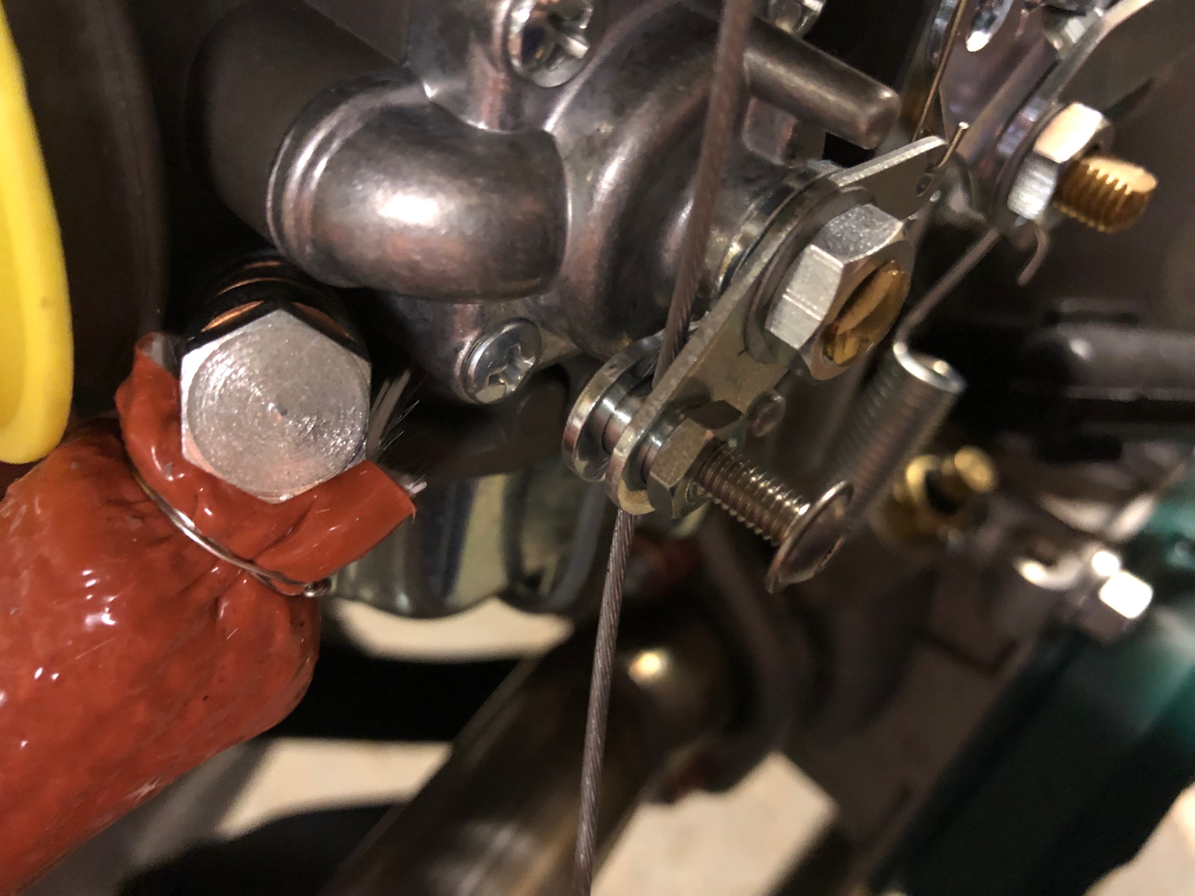
The carburettor banjo bolts are tightened not the fuel piping is complete.
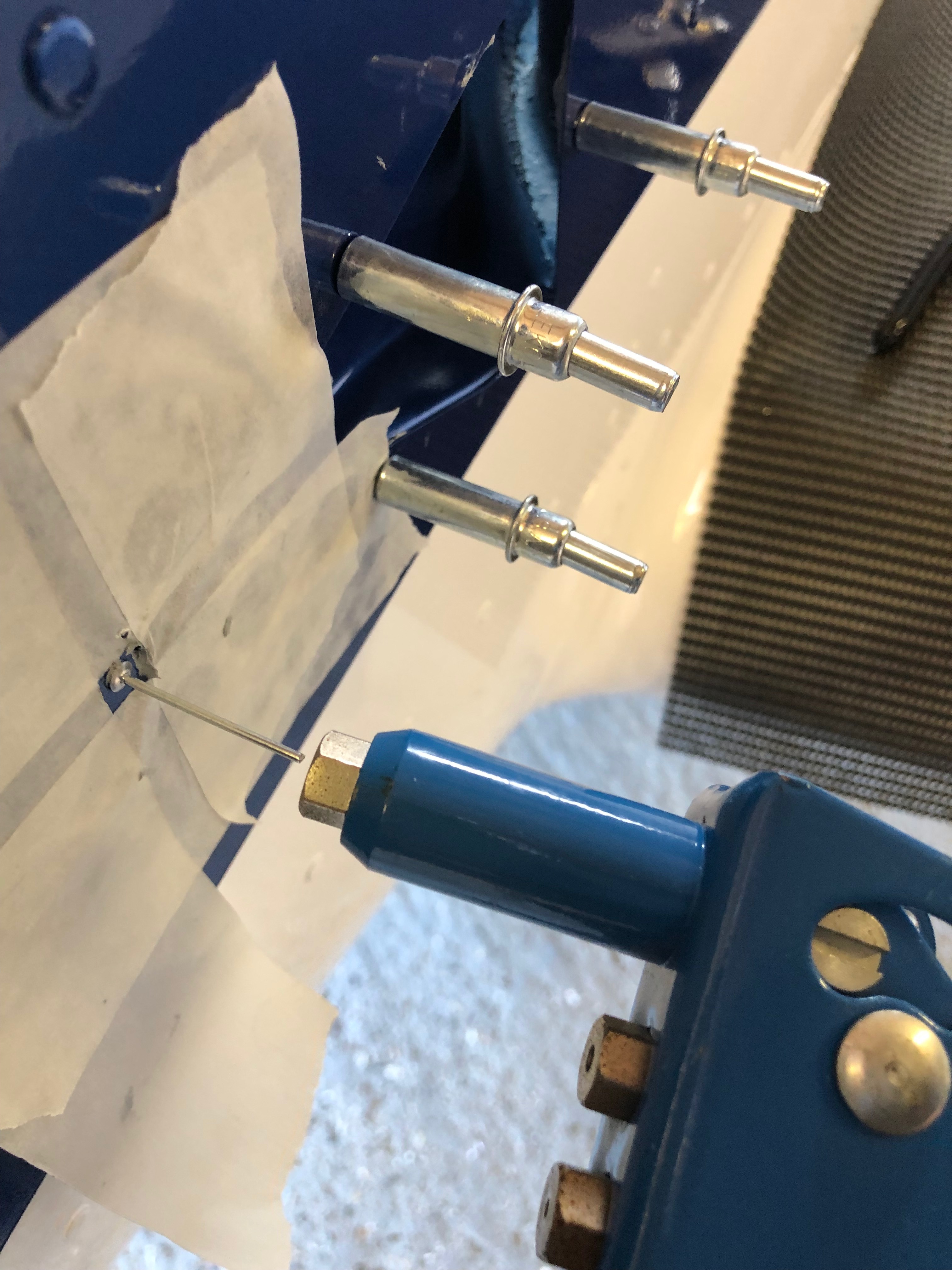
The NACA ducts are positioned and 4 x 2.5mm hole drilled to take the rivets to hold it into place.
The NACA duct in place secured by 4 temporary rivets (Clecos). The last job on this will be to add some silicon sealer to the face of the duct and rivet into place but its getting late, so time to go.
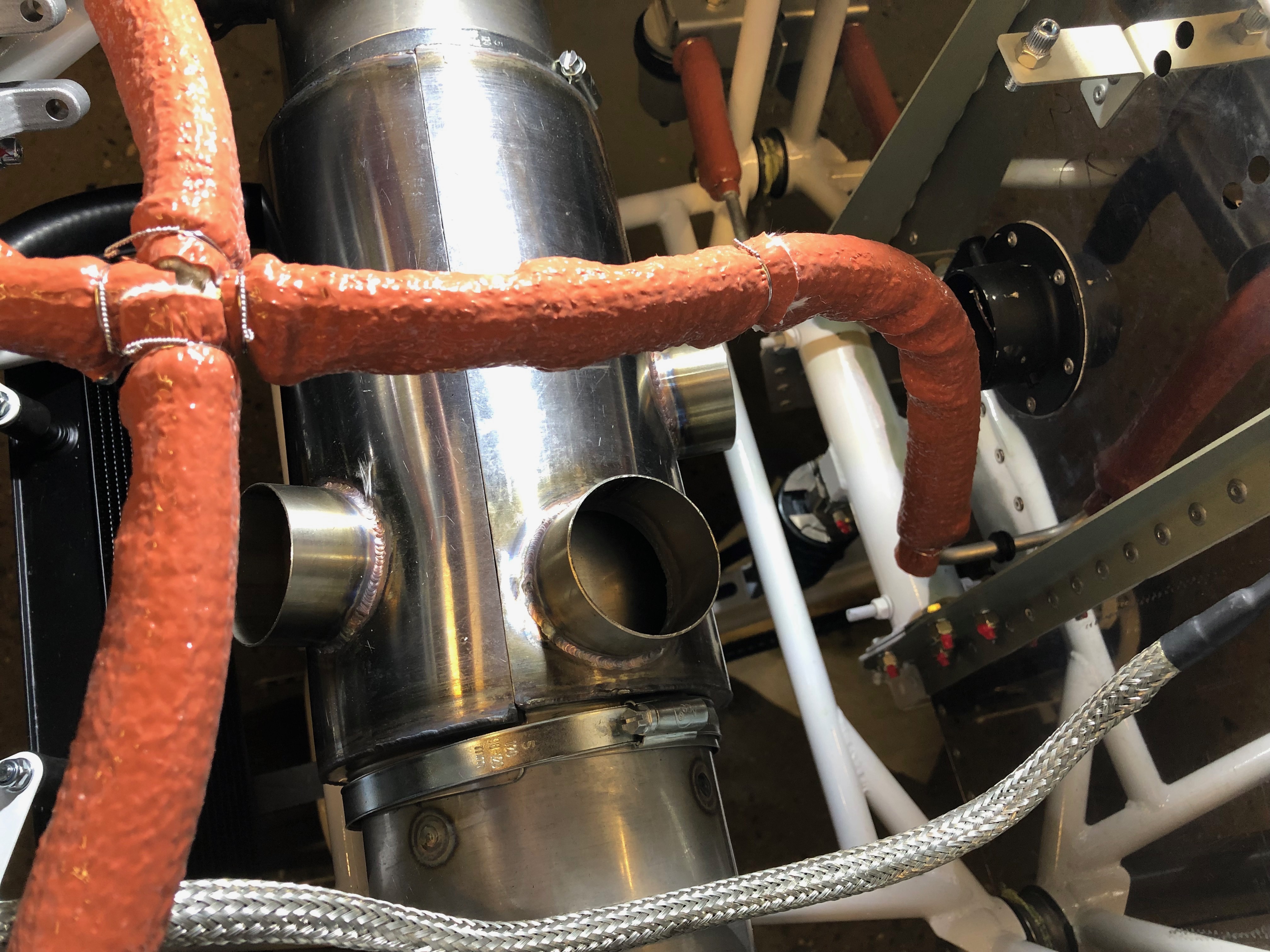
Today’s tasks included finalising the oil tank pipe run, prototyping the water radiator return hose, installing the fuel pressure sensor Tee and the ‘stand-offs’ to ensure adjacent pipes don’t rub against each other.
The water return hose requires a 22mm elbow to enable it to fit the installation. I’ve used an ordinary copper solder ring plumbing elbow. The solder ring gives a raised ring that allows the clamp to hold the fitting securely.
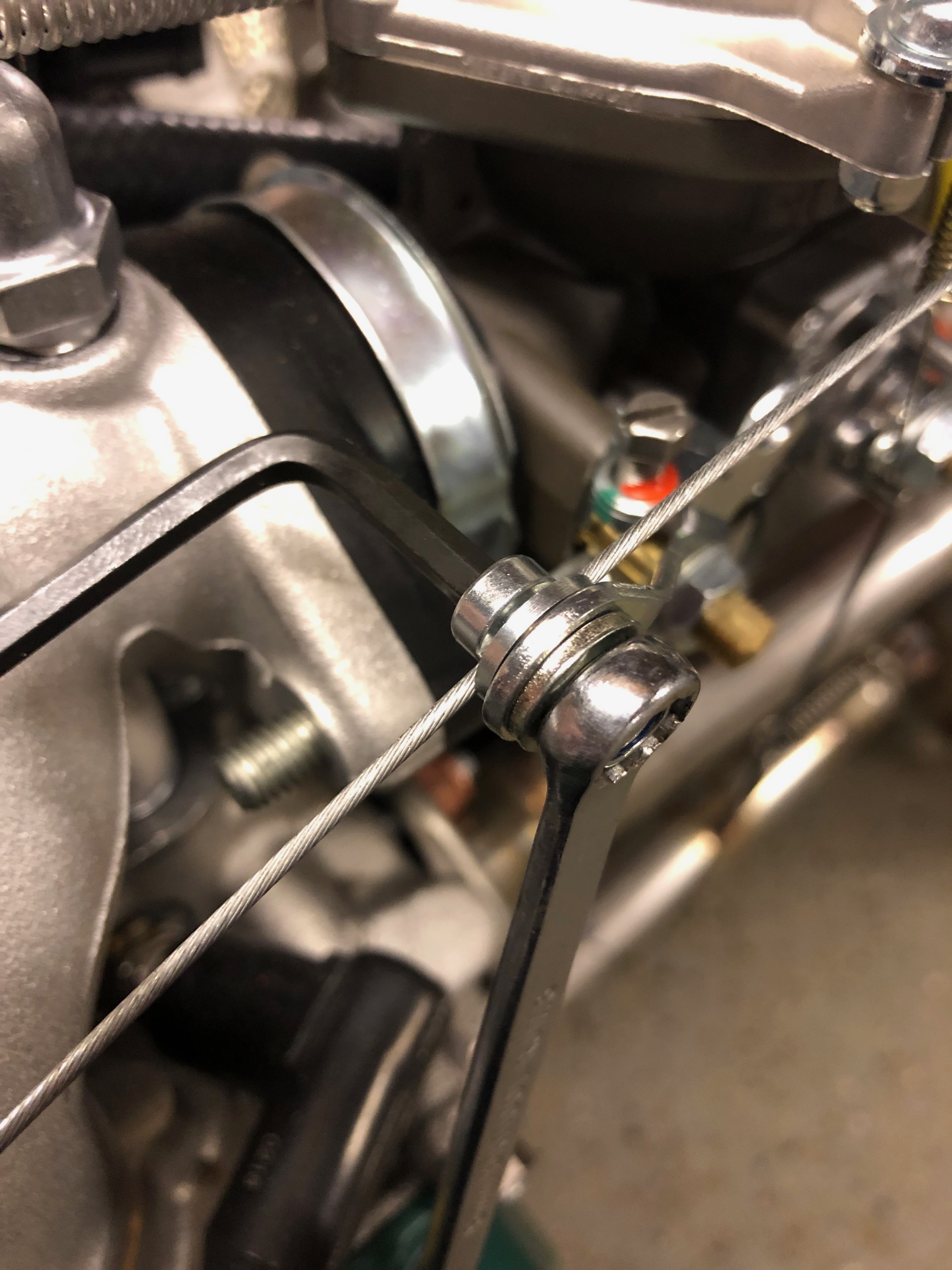
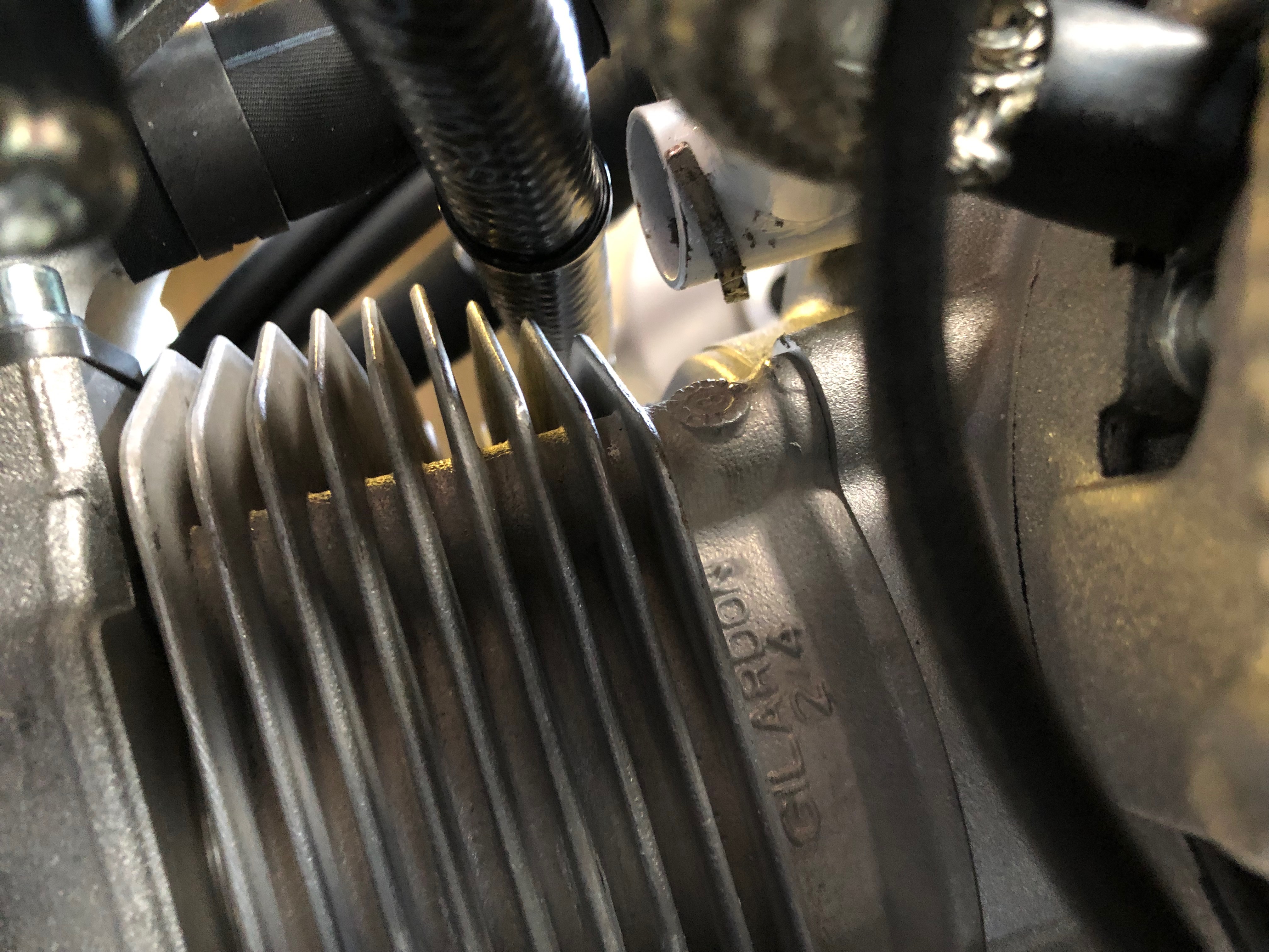
After running the hoses most need stand offs to make sure they don’t rub on adjacent pipes
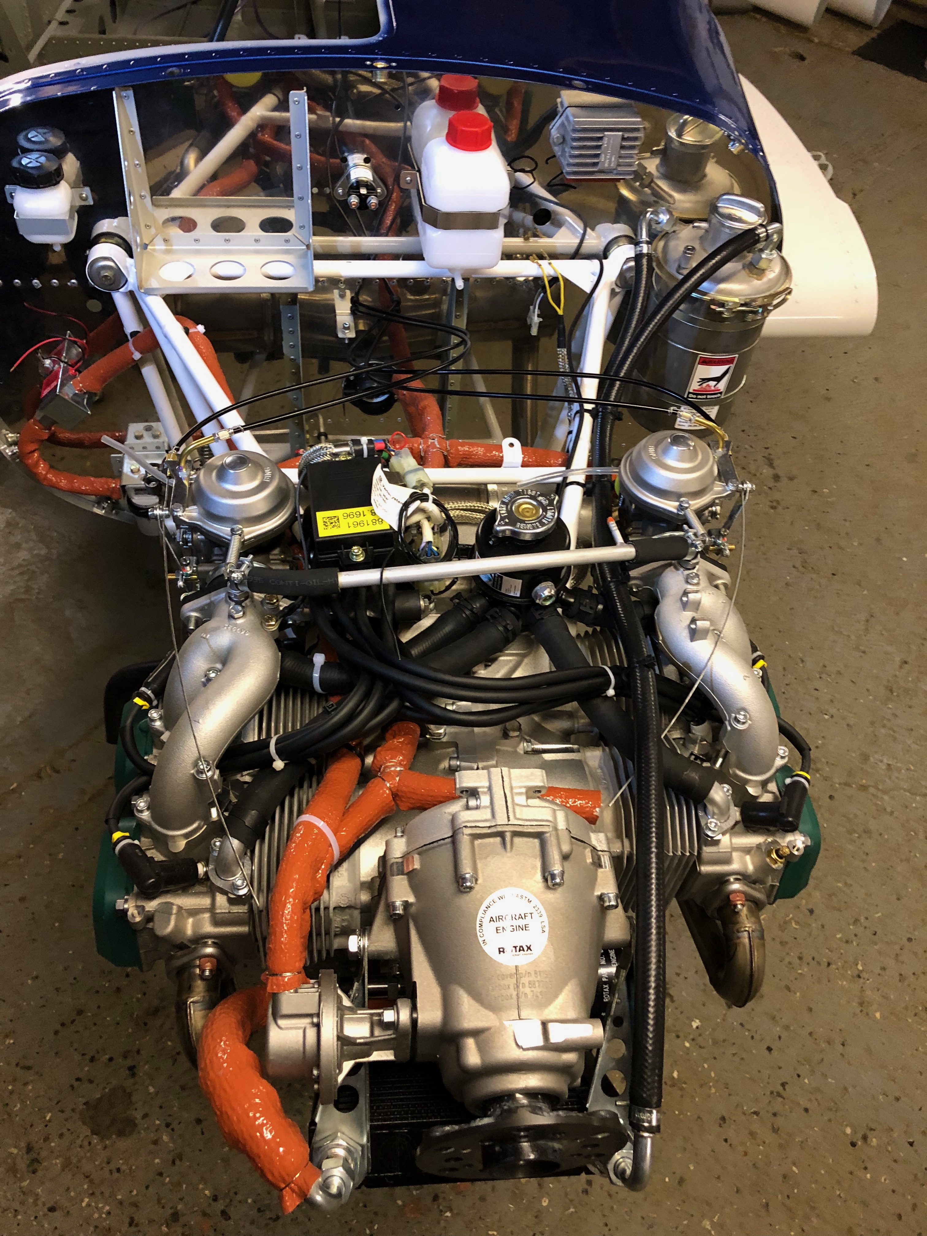
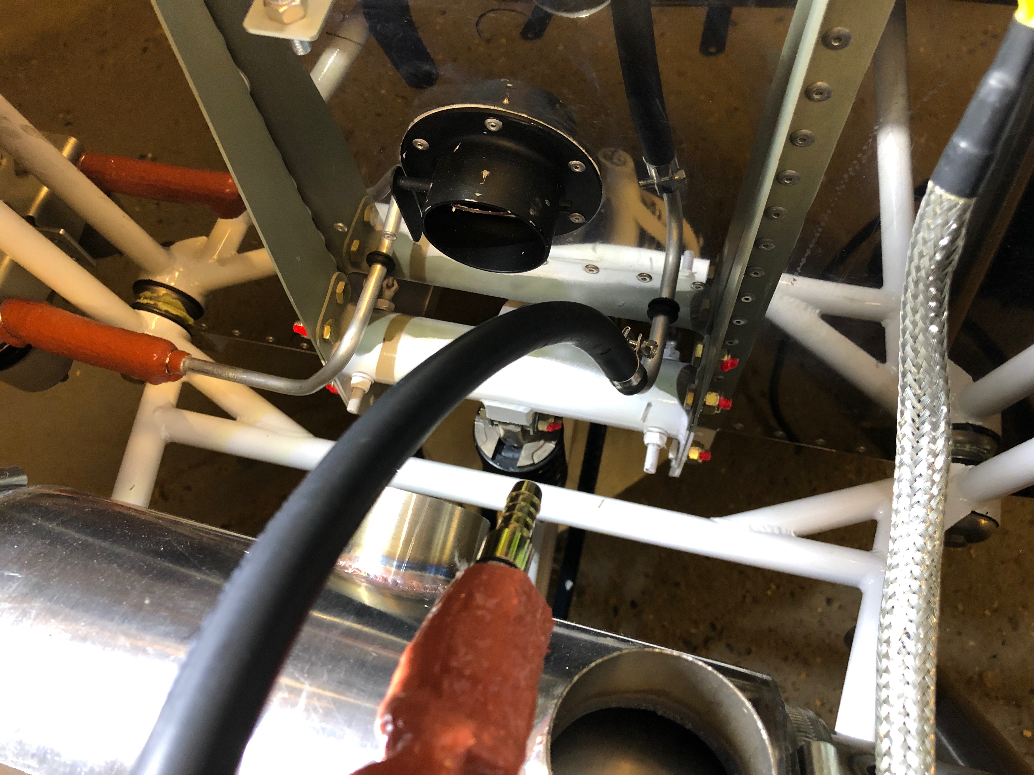
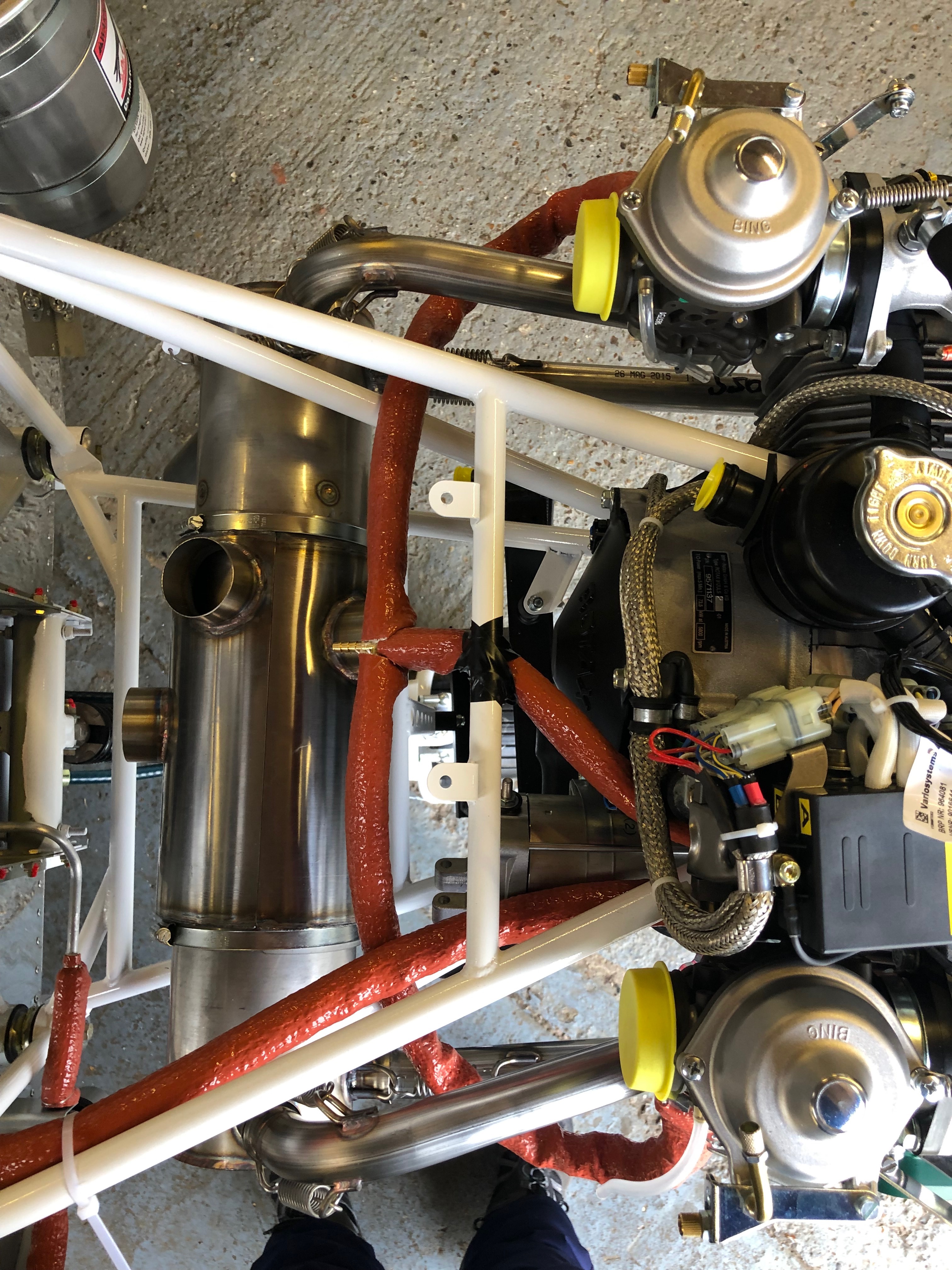
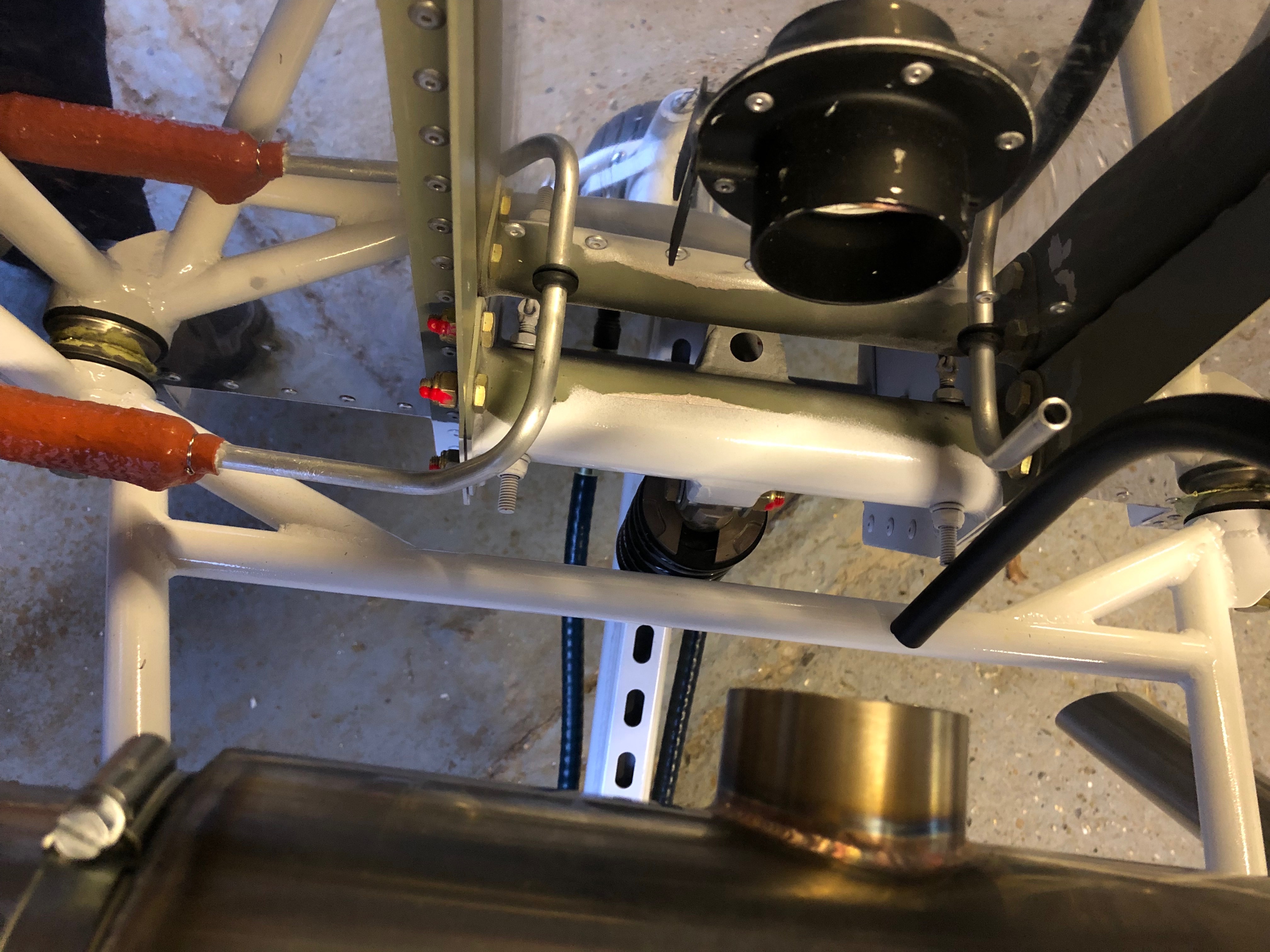
A view from the top showing the fuel pressure switch just behind the gearbox and the top oil hose on the left.
Today was set out to redo some piping that I wasn’t happy with, re site the water radiator support bracket that seemed to be straining then continue the fuel system and oil system install.
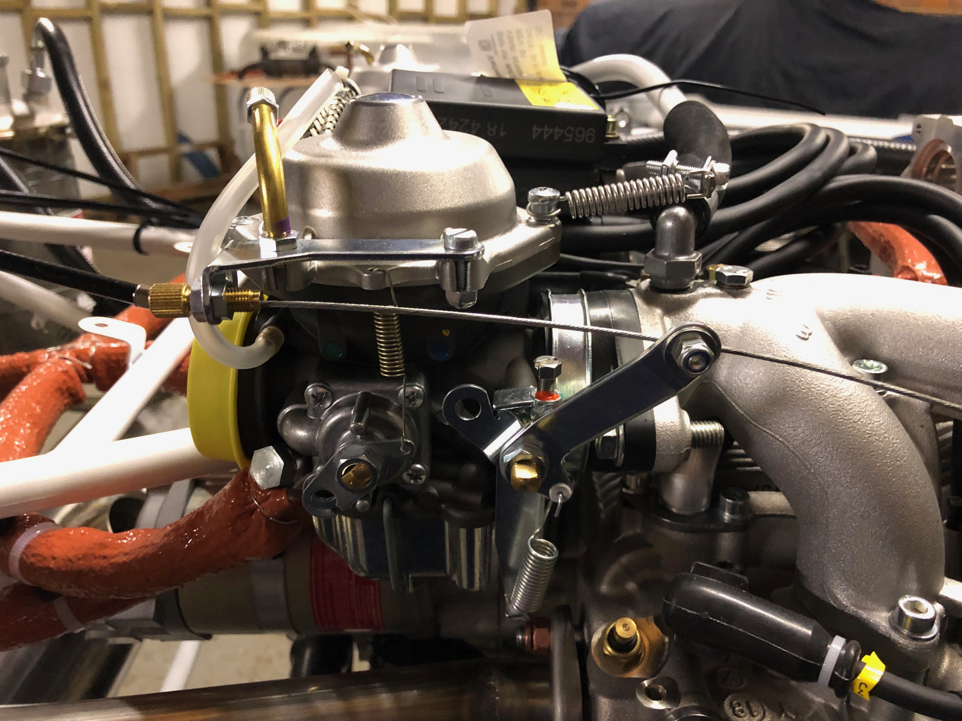
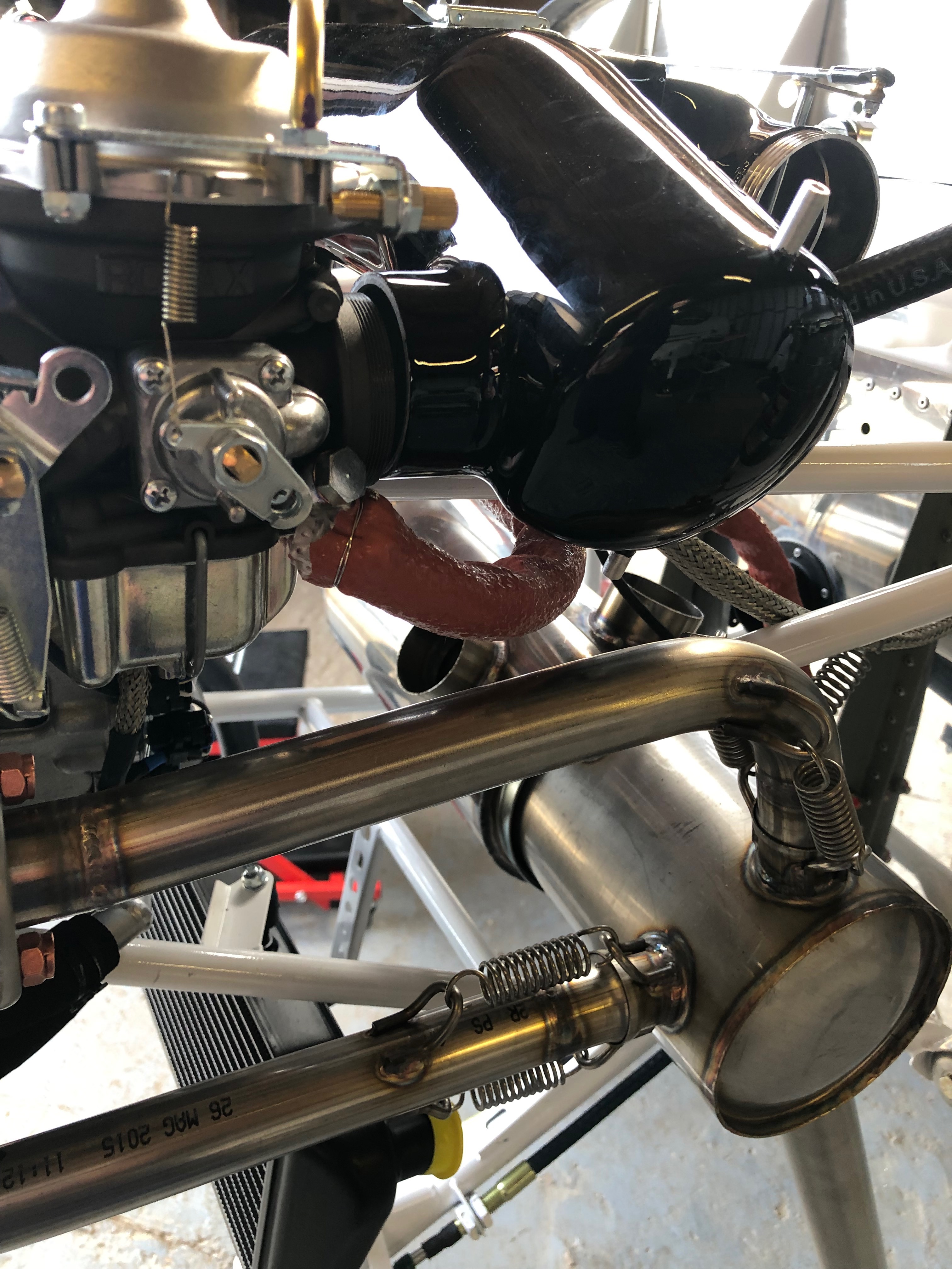
I wasn’t happy with this pipework so I changed the angle of the carburettor banjo and shortened the fuel pipe.
The change resulted in a much neater installation.
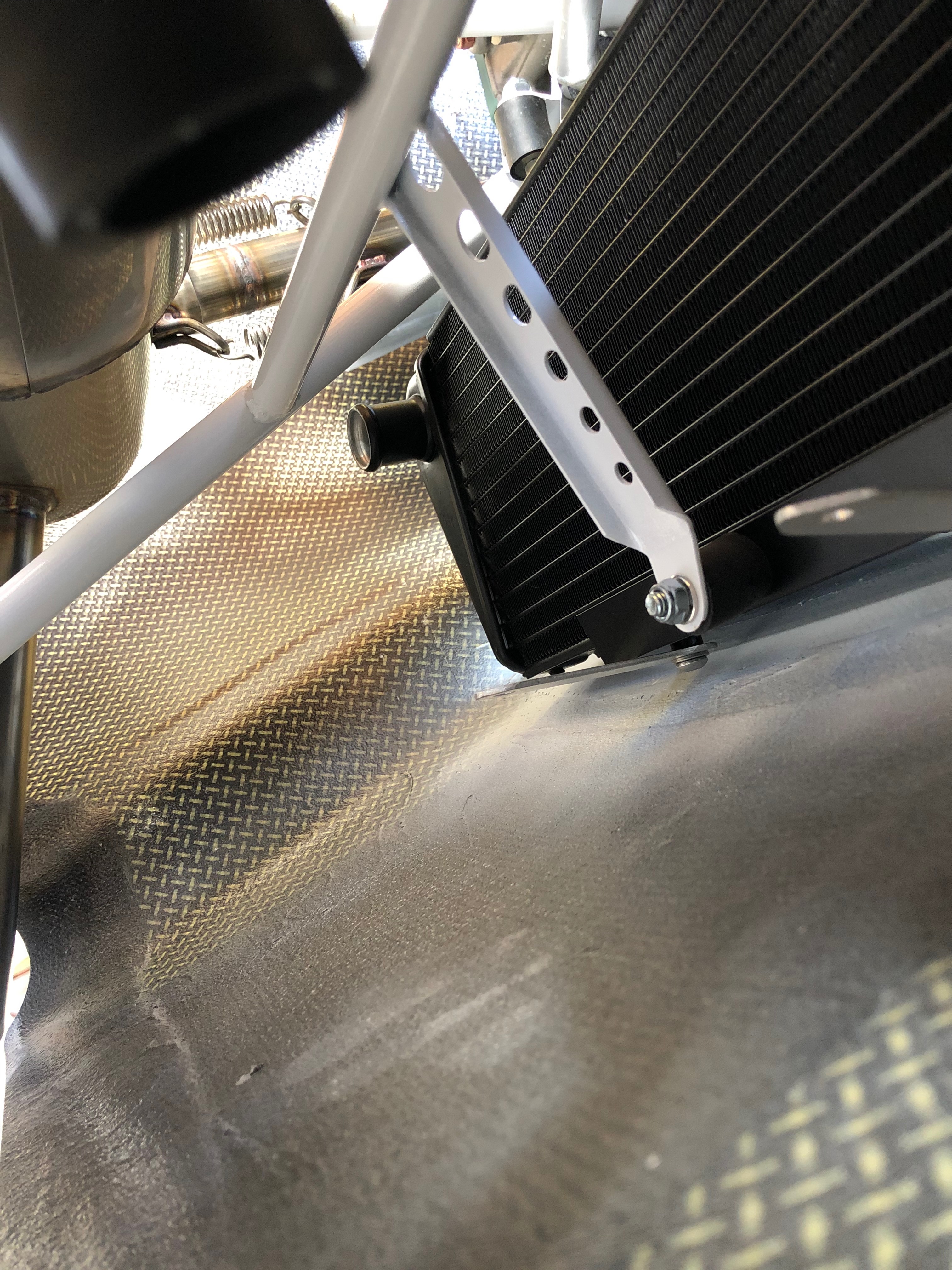
The aluminium water radiator brackets were moved to underneath the black bracket which seems to work much better than the original fit.
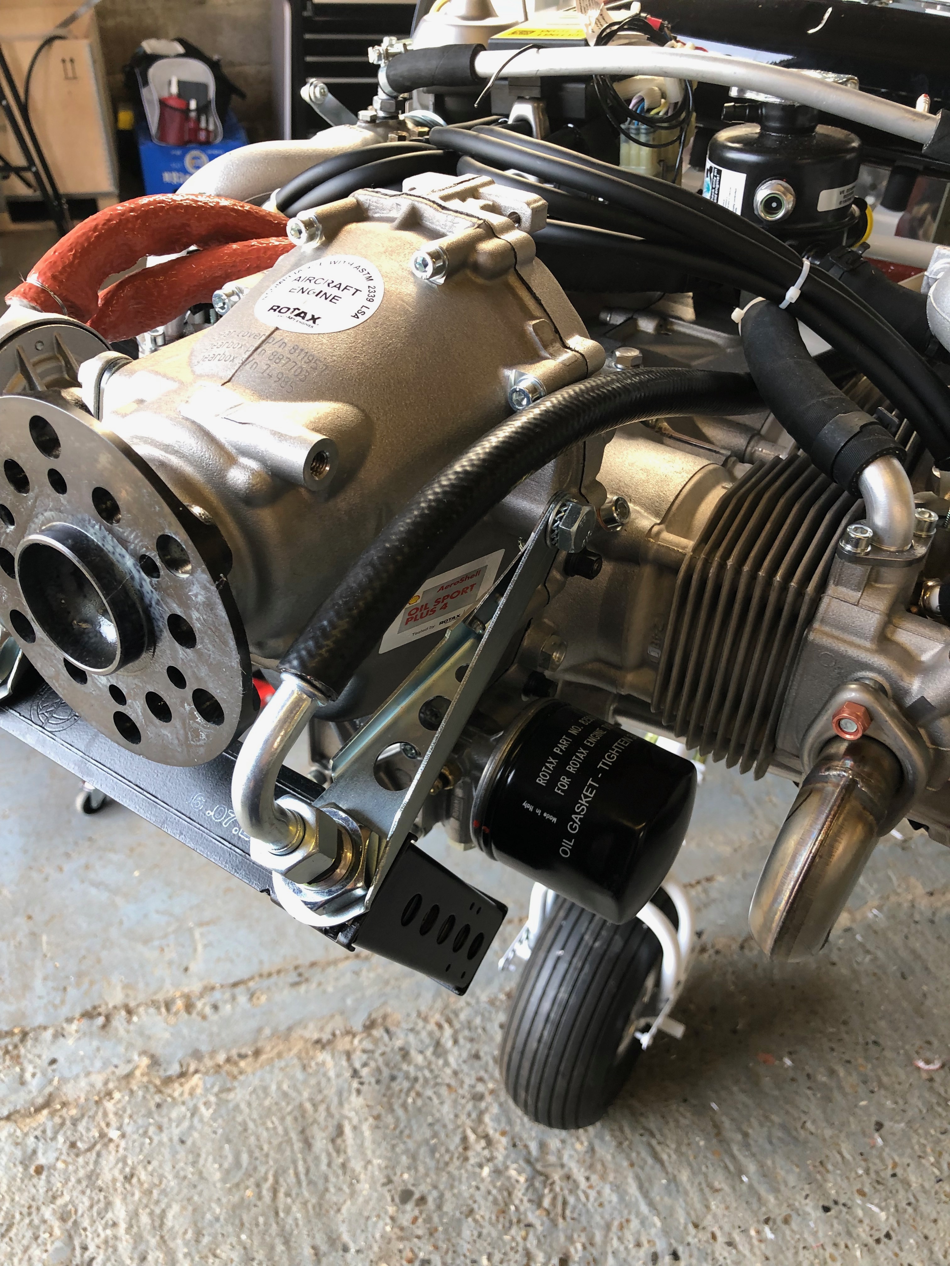
The oil system is next. Most of the time taken to install the piping is working out the the route to make sure that it doesn’t rest or rub on other parts of the engine and it has a natural route which doesn’t lead to kinking of the pipe.
The oil supply hose is fairly easy to route but still requires careful positioning and ‘stand-offs’ to make sure nothing rubs.
There’s not a lot of space as you can see here.
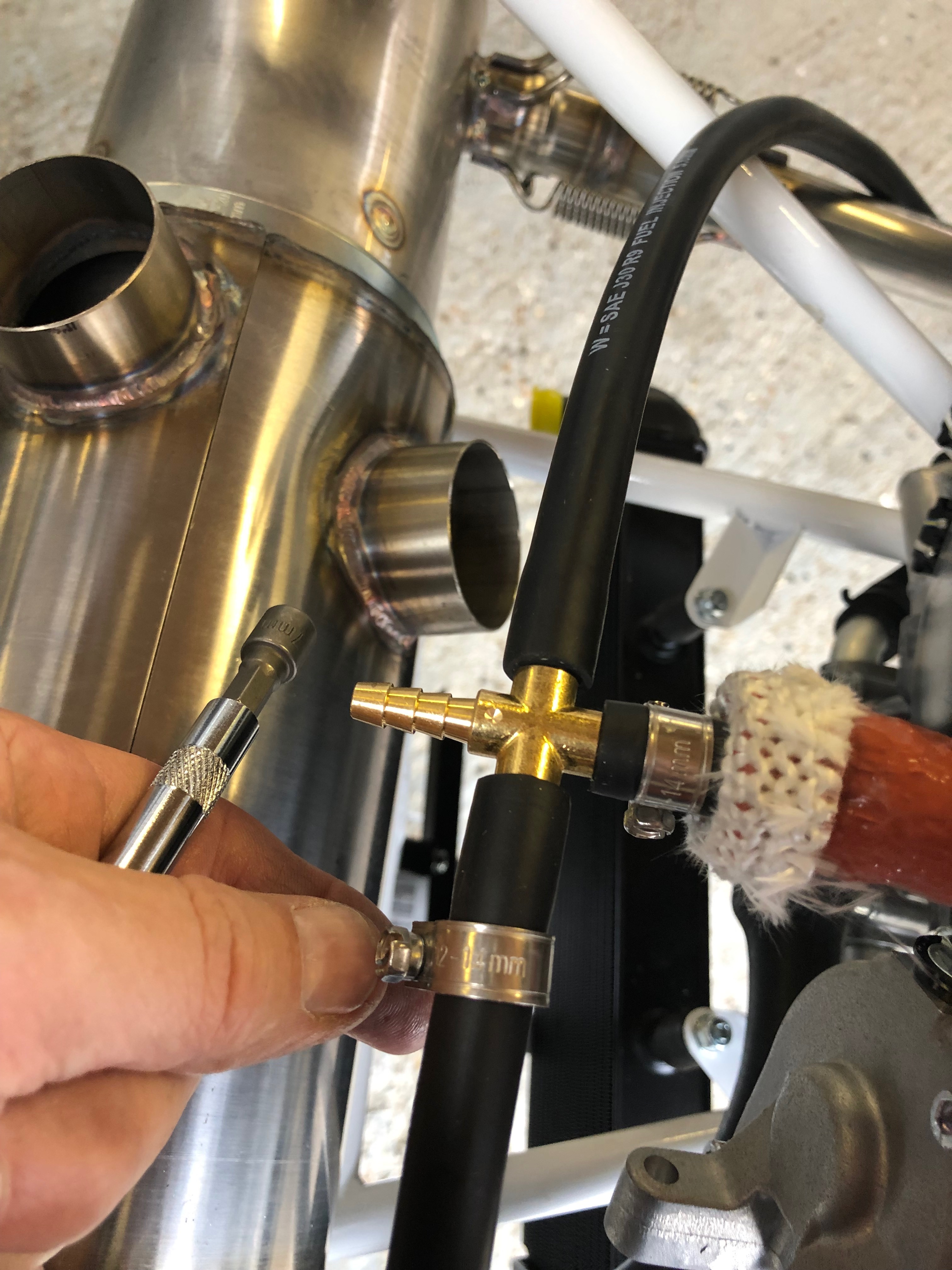
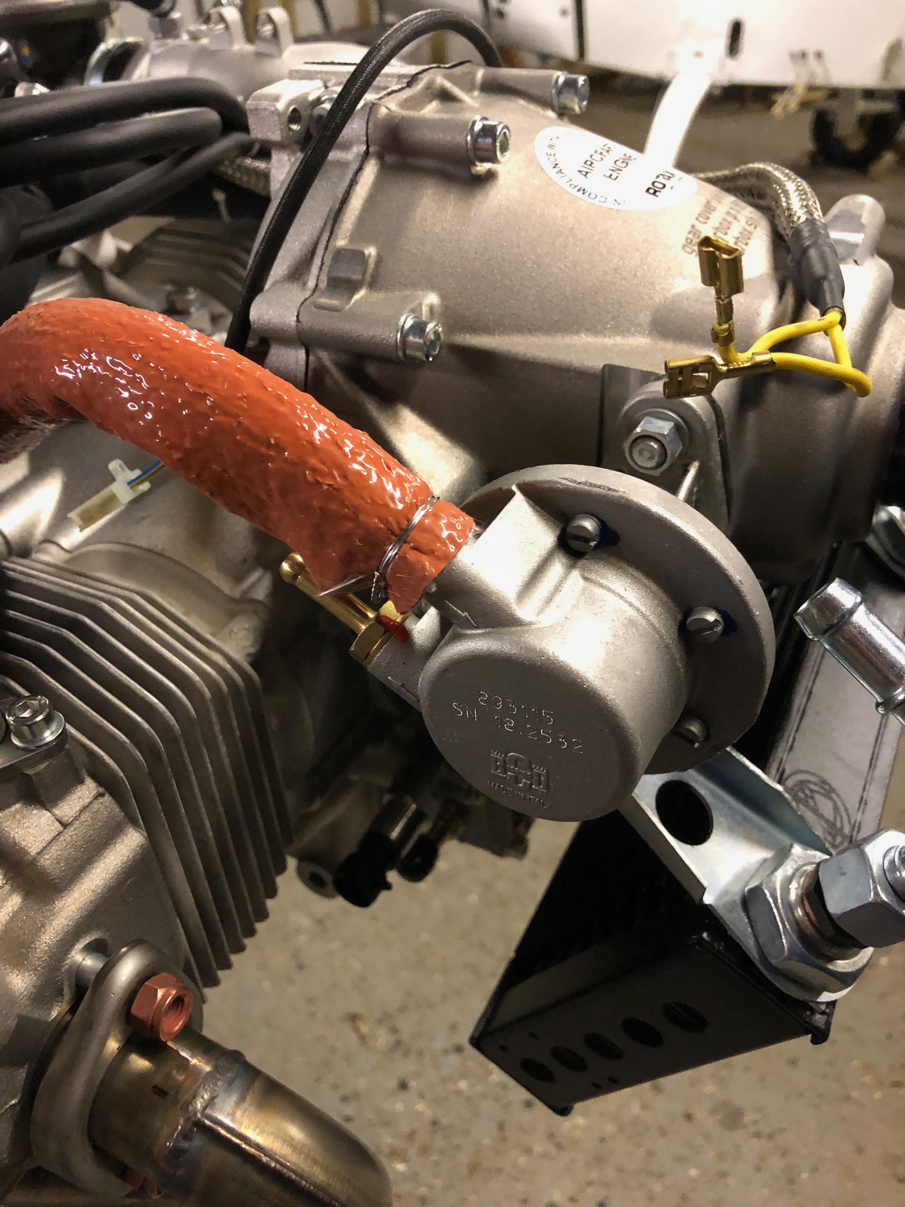
Last job for today is to make the tee for the fuel pressure sensor. This will be fitted in the fuel line between the mechanical fuel pump and the cross connector that has the restrictor installed. This will ensure that the sensor reads the correct pressure.
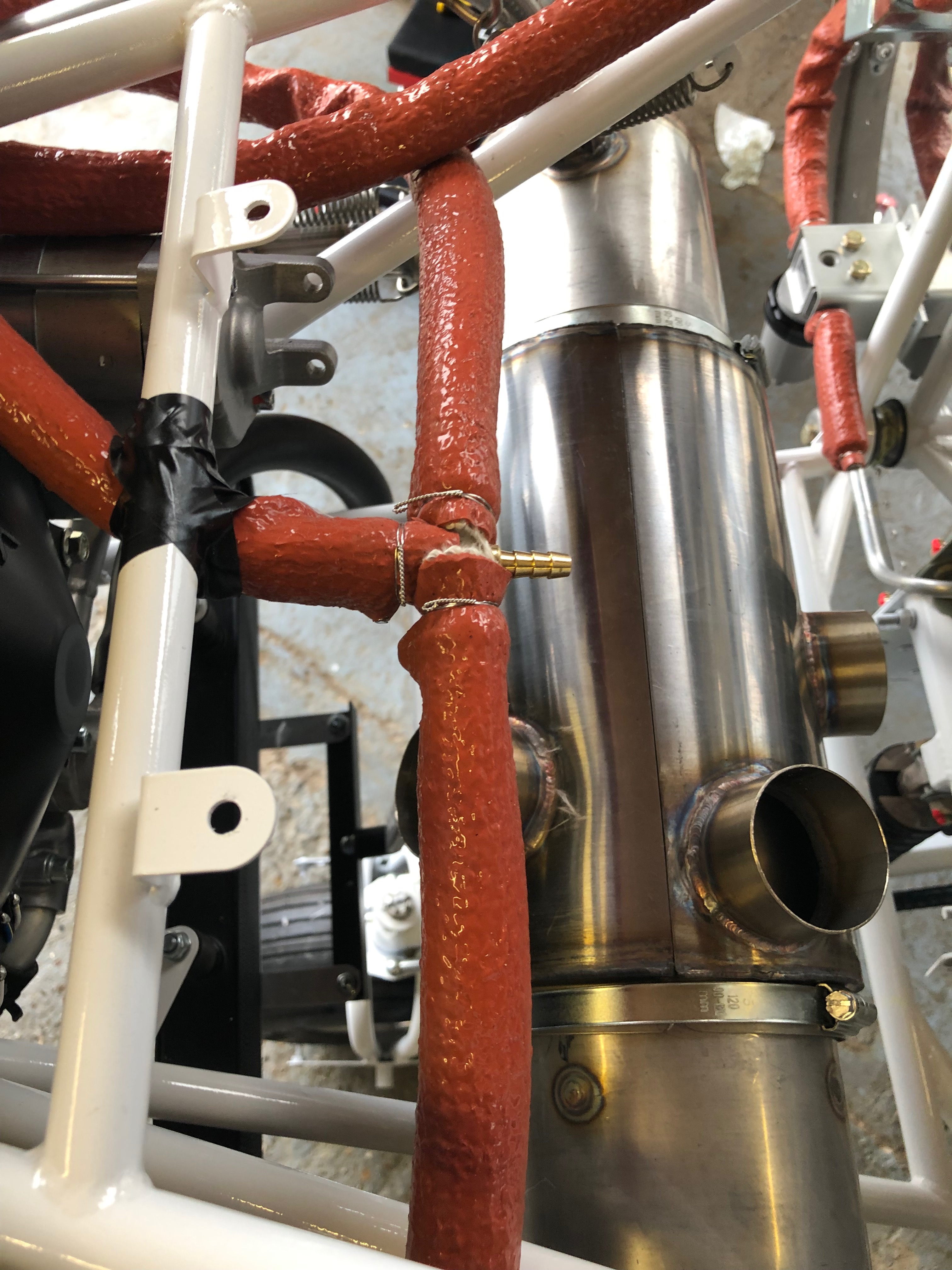
The Tee must also have fire sleeving and secured in place with wire wrap.
First thing to do today was to fit a grommet in the firewall for the aluminium fuel pipe to go through and be supported and stop it chaffing.
The final screws arrived so I can now completed the installation of the water radiator.
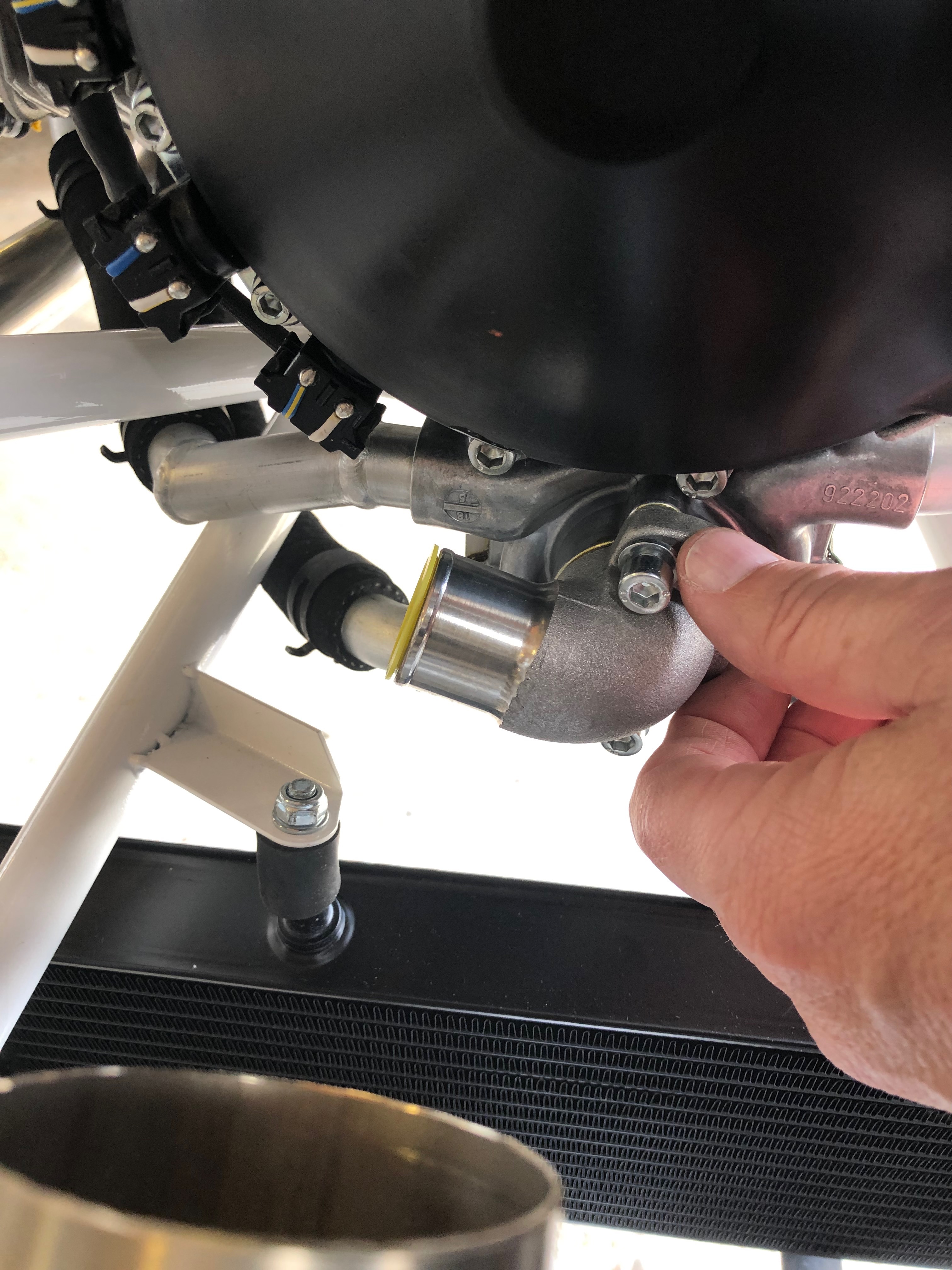
The water pump outlet needs to be repositioned to allow it to be piped to the radiator.
Trial fitting of the pipe to make sure the pipe run doesn’t snag any other pipes or brackets.
Re-fitted the water pump outlet and tightened the screws with Loctite 643
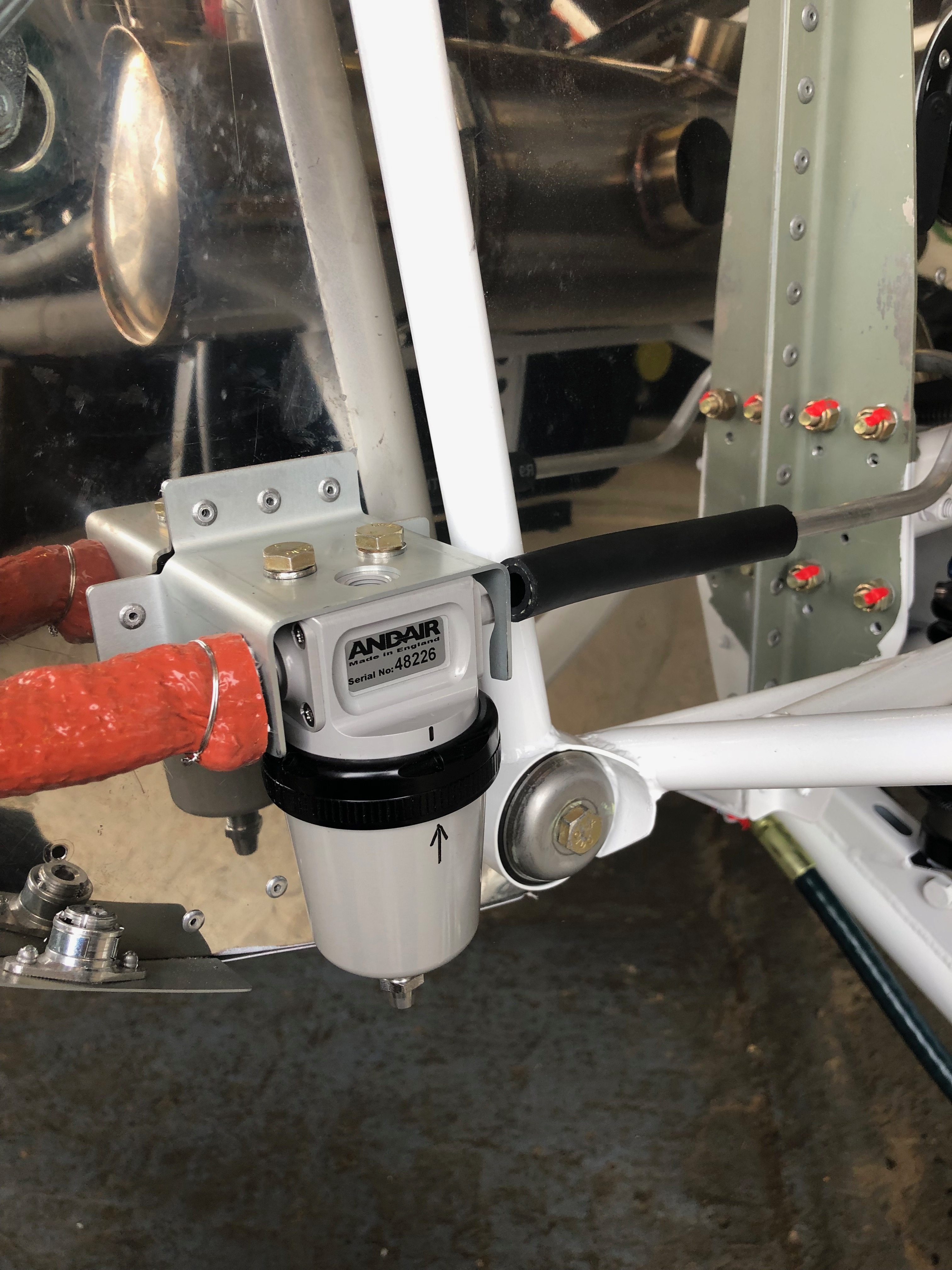
Now the grommet has been fitted I can complete the installation of the fuel feed piping to the gascolator.
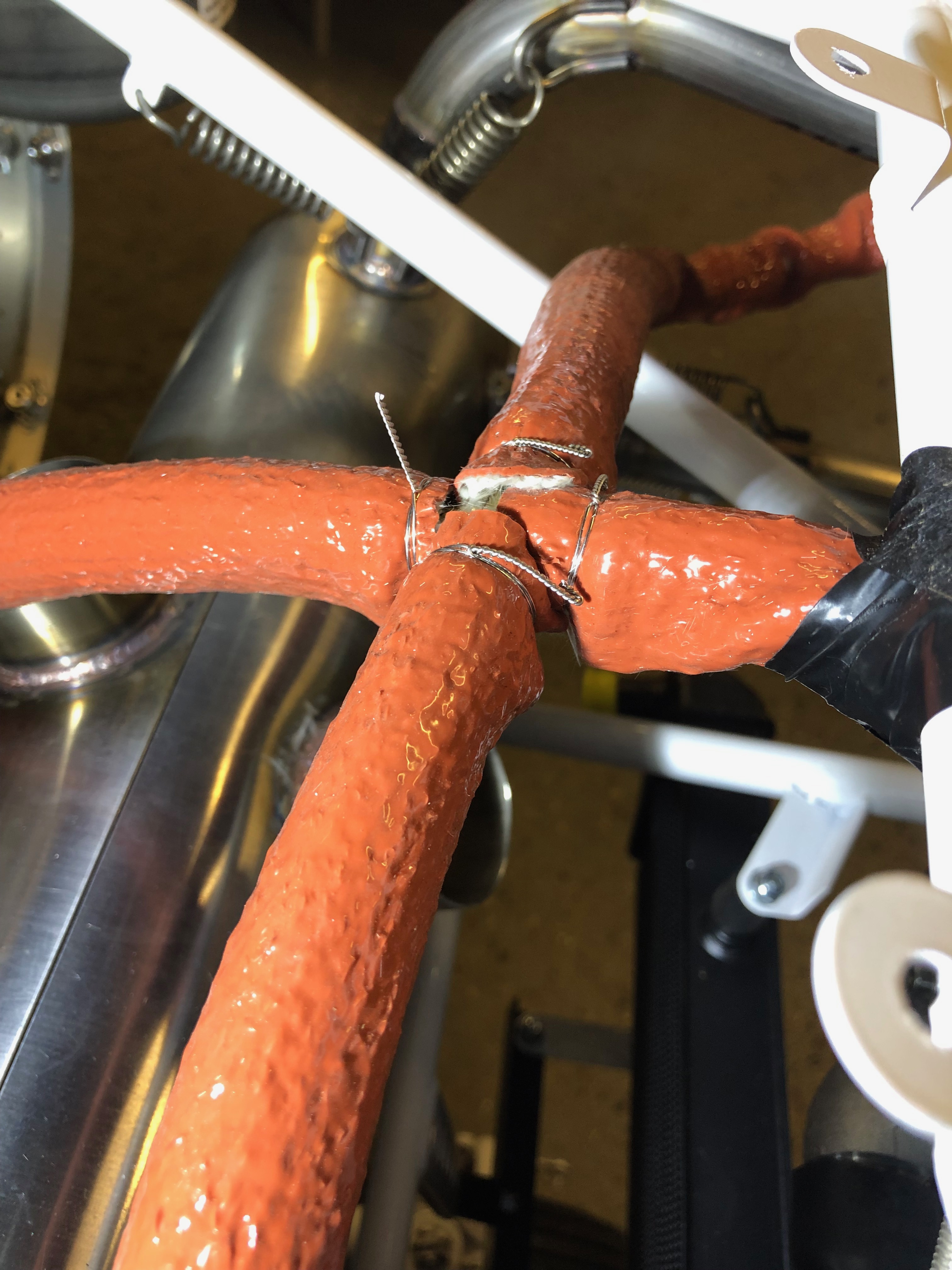
All the pipes are clamped with a hose clamp and fire sleeving is slid over the whole assembly and secured with aircraft grade stainless steel wire wrap. This ensure the fire sleeving doesn’t move and ensures the fuel pipes are protected in the event of an engine fire.
An example of a completed wire wrap.
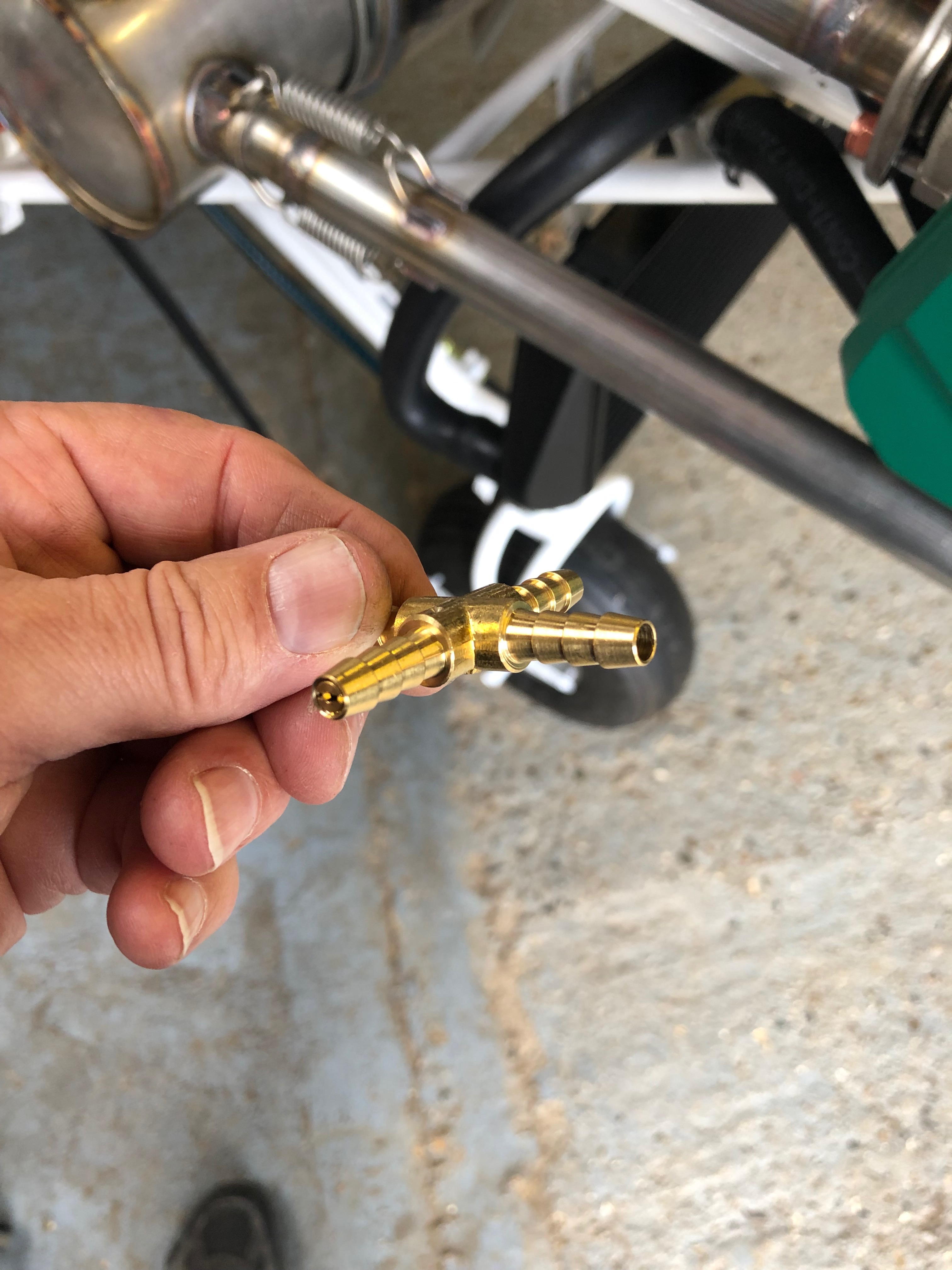
The flow from the mechanical pump supplies the carburettors and then a return is taken to the lefthand fuel tank this allows a constant feed of fuel to circulate the fuel system and alleviates the chance of a vapour lock. The return feed is restricted by an insert in one branch of the cross connector (see photo) this ensures the carburettors get sufficient supply of fuel.
The cross connector centrally installed with the return line connection still to be completed.
An view from overhead showing the positions of the pipework to date.
view form the left hand side Before the return line is installed the aluminium return pipe needs to be fitted.
It’s a tight squeeze in the nose wheel tunnel but with perseverance the connection is made and the hose clips tightened. This piece of tubing doesn’t need the fire sleeving because it is behind the firewall.
Return pipe installed.
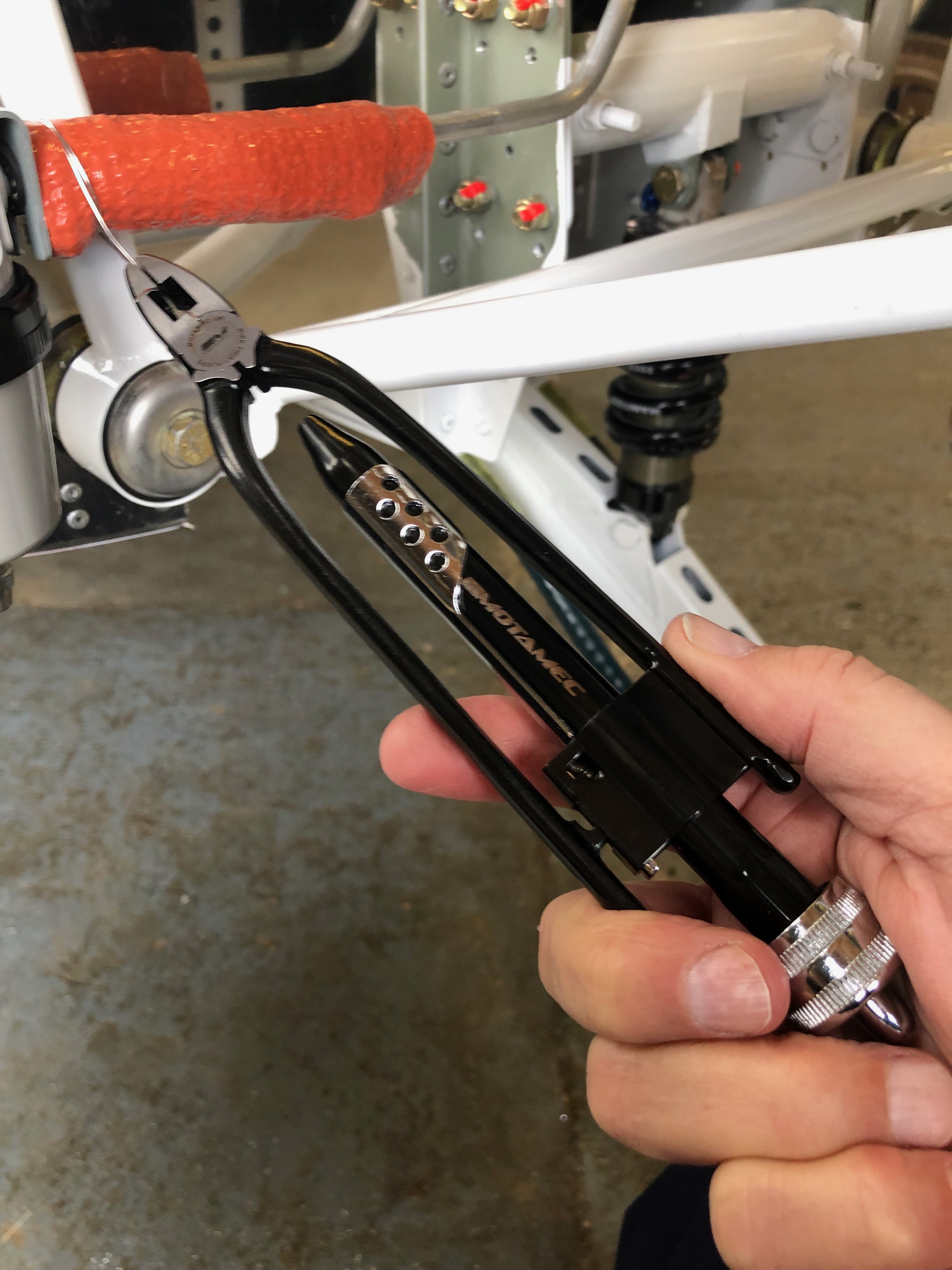
Once a wire wrap has been carried out the end is cut off as leaves a very, very sharp barb. To ensure that it doesn’t cut into you when carrying out maintenance the end it bent over on itself and pushed down .
The return line now completed.
I completed the piping to the carburettors but having reviewed the run I’ve realised that it’s not the best installation. I will re run the pipes tomorrow so they are a lot shorter and won’t run round the exhaust like they are in this photo.
Took delivery of fuel pipes, gascolator and fuel selector today, so plenty to get on with.
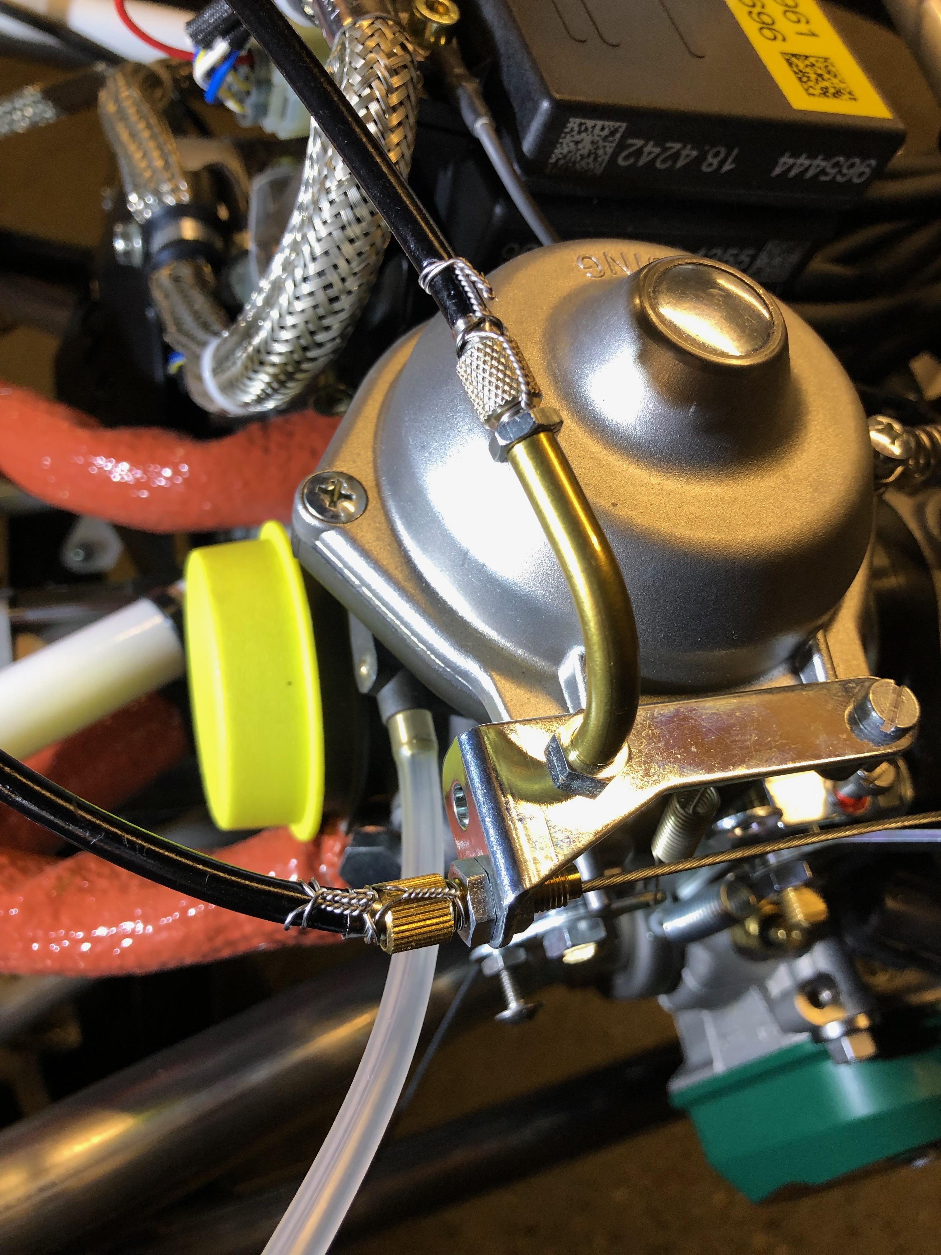
First job of the day was. Install a grommet in the modified oil bracket to stop the pump breather tube rubbing against the bracket.
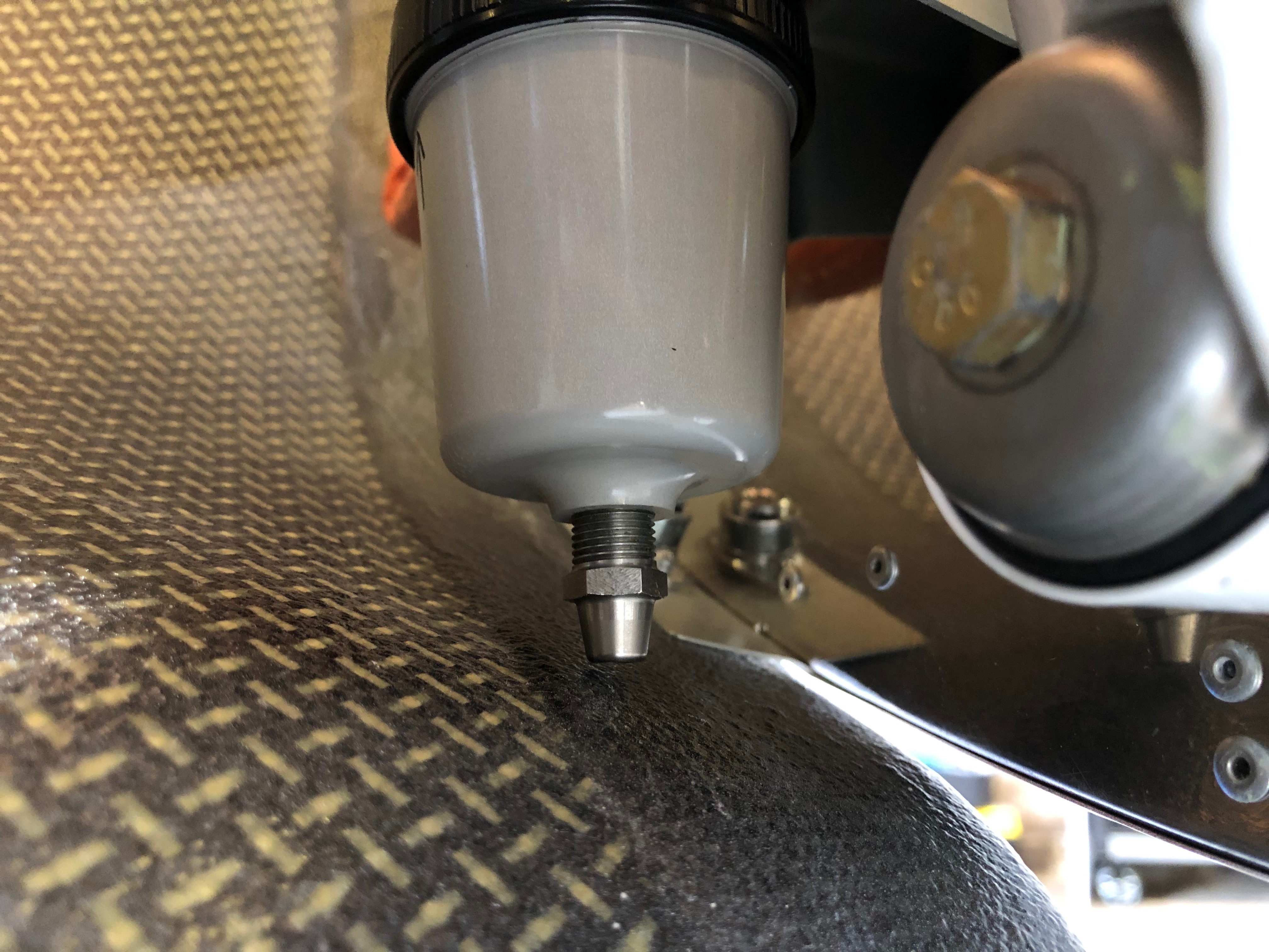
Andair Gascolator
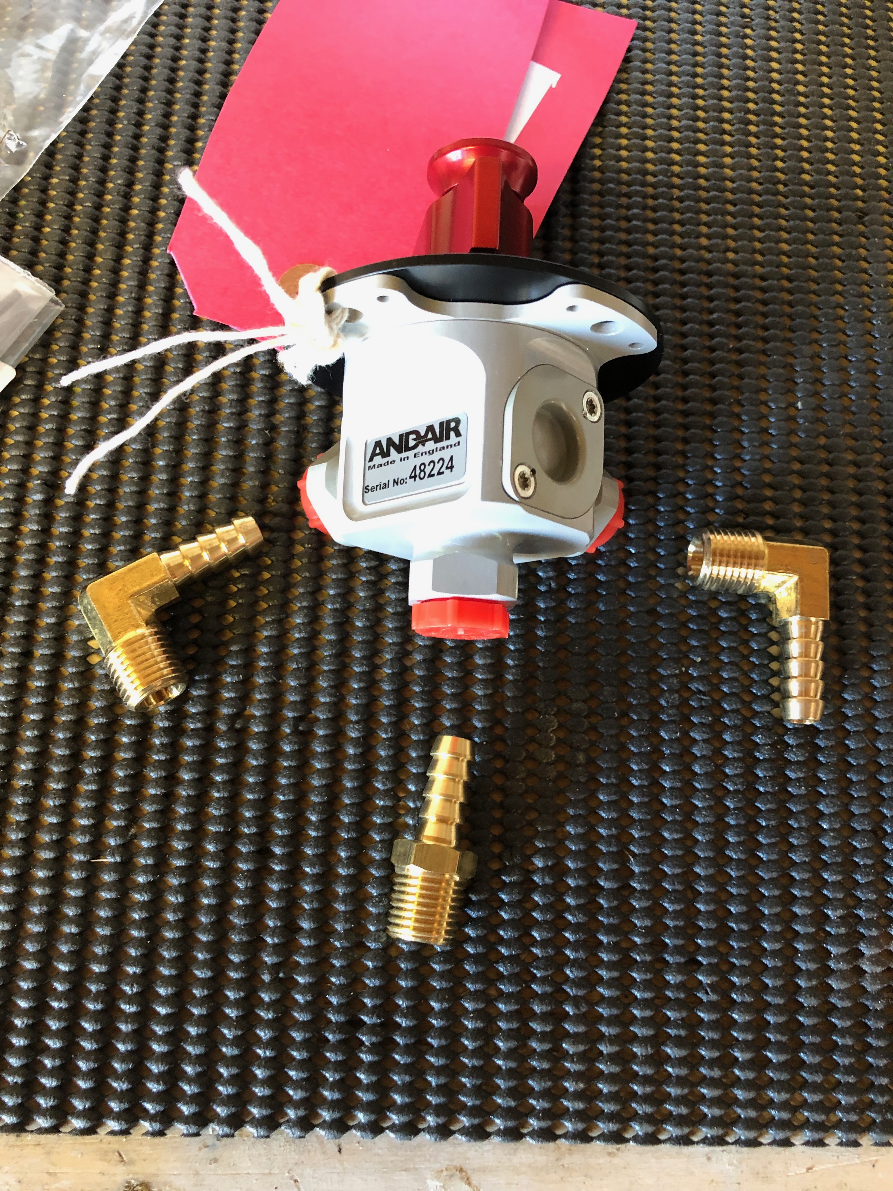
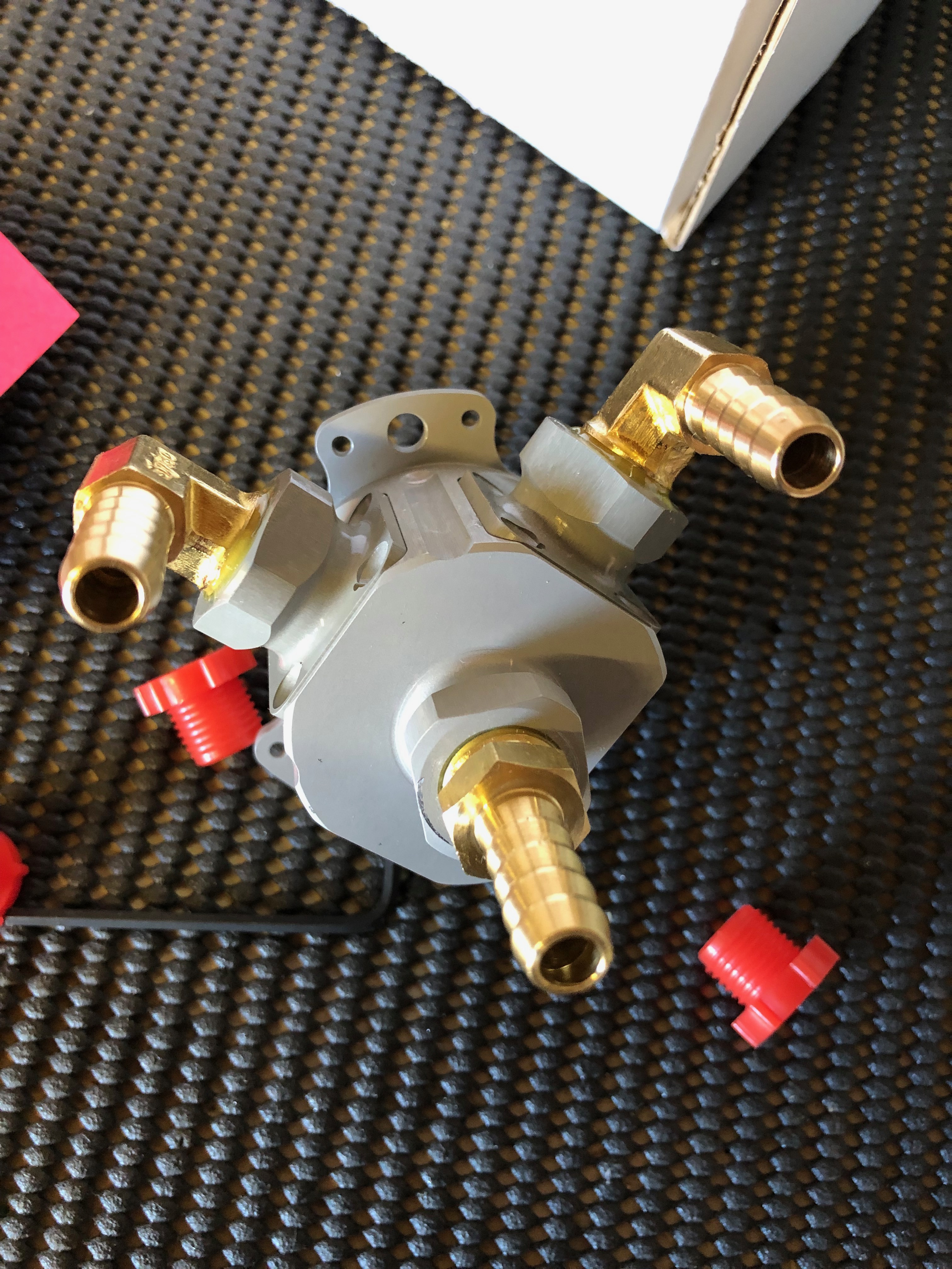
Andair Fuel selector
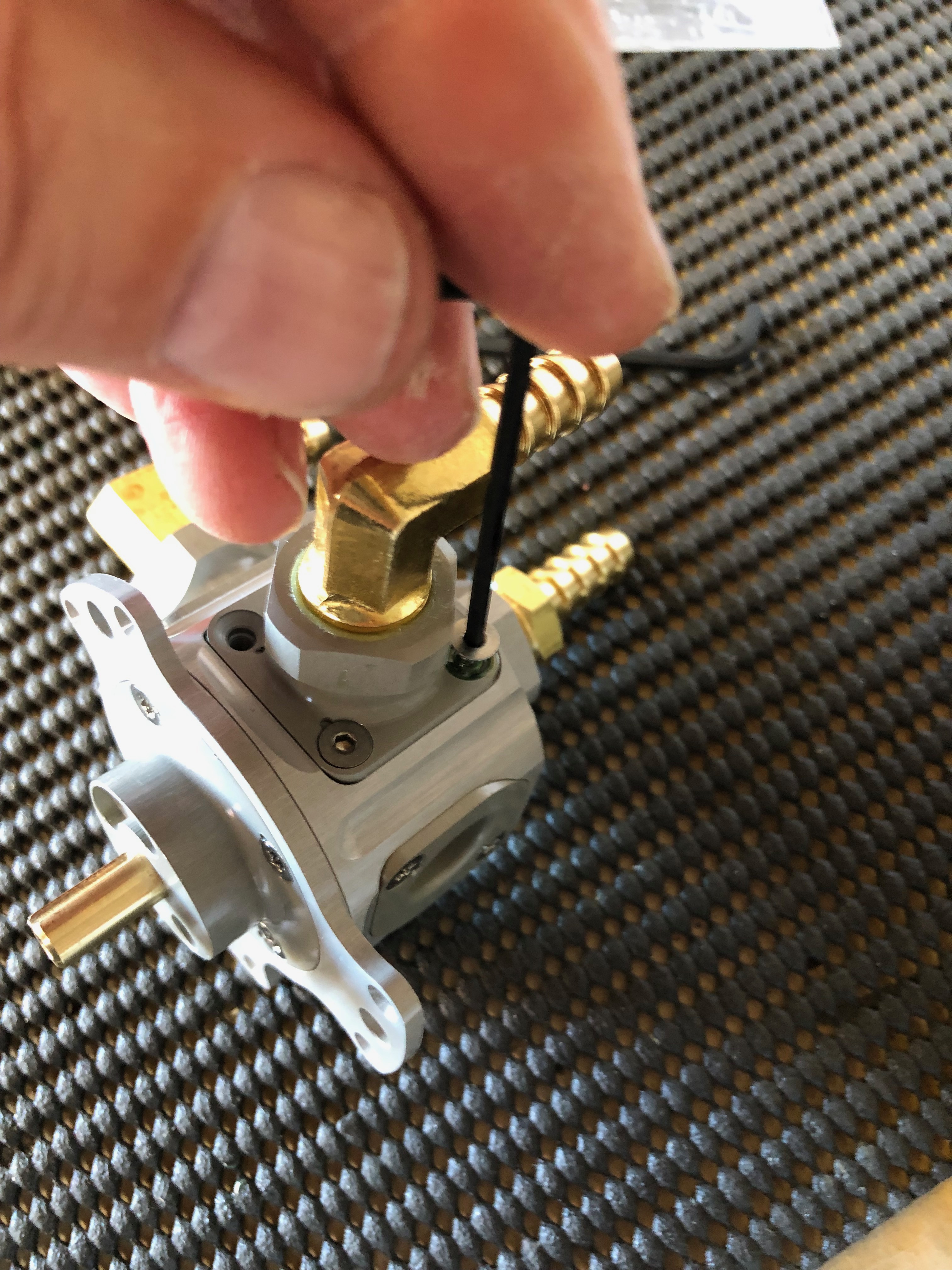
Gascolator drain valve
The drain valve needs to be installed with Loctite 577 to seal the thread.
The fittings for the fuel selector need to be fitted. Again using Loctite 577.
Fittings positioned as required.
Secured using screws provided and locked with Loctite 648
The fuel pipe from the fuel selector has to be connected to a short piece of formed aluminium with a piece fuel hose.
The pipe runs through the firewall and needs to be protected from abrasion by inserting a grommet in the firewall. It also acts to support the pipe.
The gascolator mounting bracket needs to be modified to allow the unit to be installed.
Once installed, the fuel pipes can be fitted.
Once the fuel pipe is secured the fireproof sleeving is slipped over the pipe and wire locked to stop it moving. The aluminium pipe running through the firewall can be seen on the right.
The connection to the pump is made next.
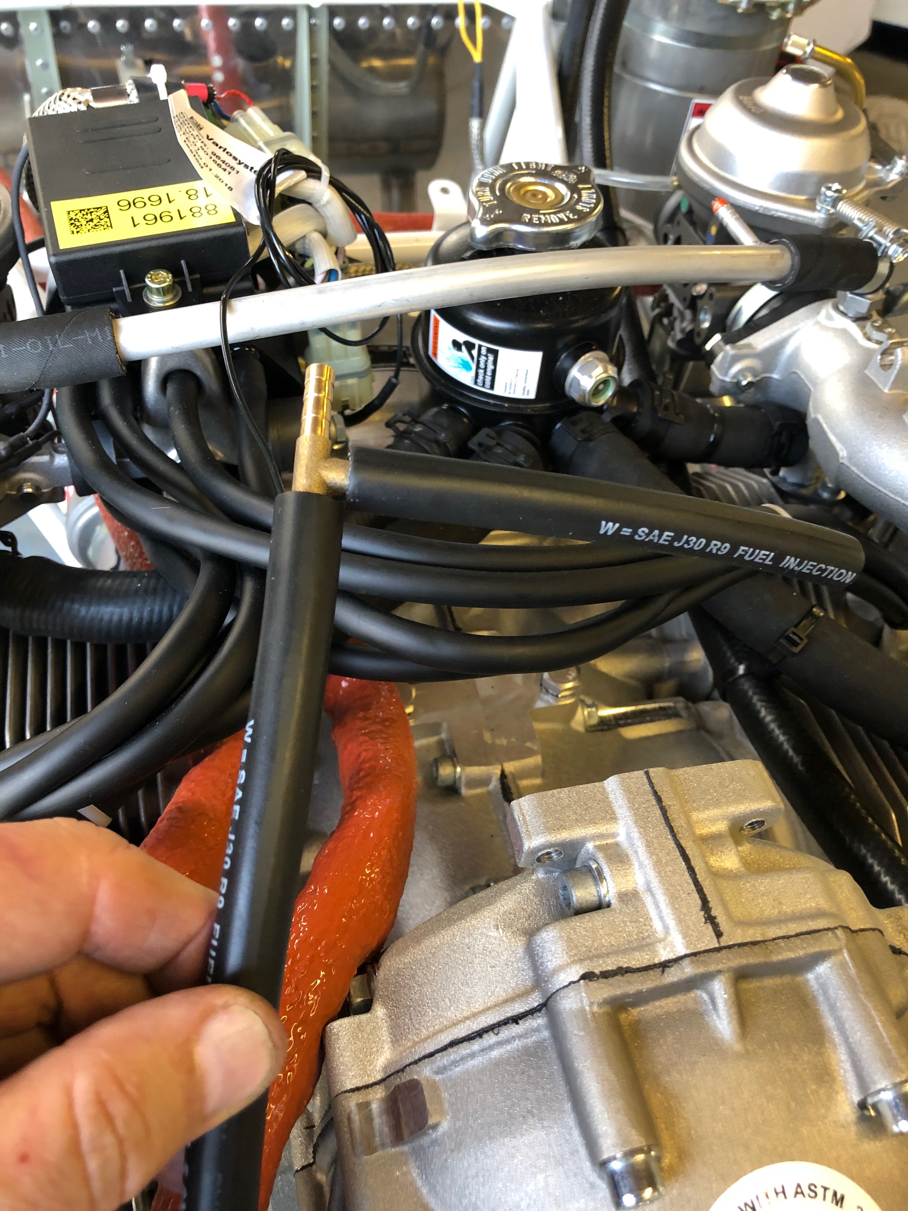
The next stage is to run 6mm R9 fuel pipe from the mechanical fuel pump to the 4 way connector that supplies fuel to the carburettors and provides a restricted return to the lefthand fuel tank.
Following the build of my Bristell NG5 Kit No. 382 Registration G-MLSY