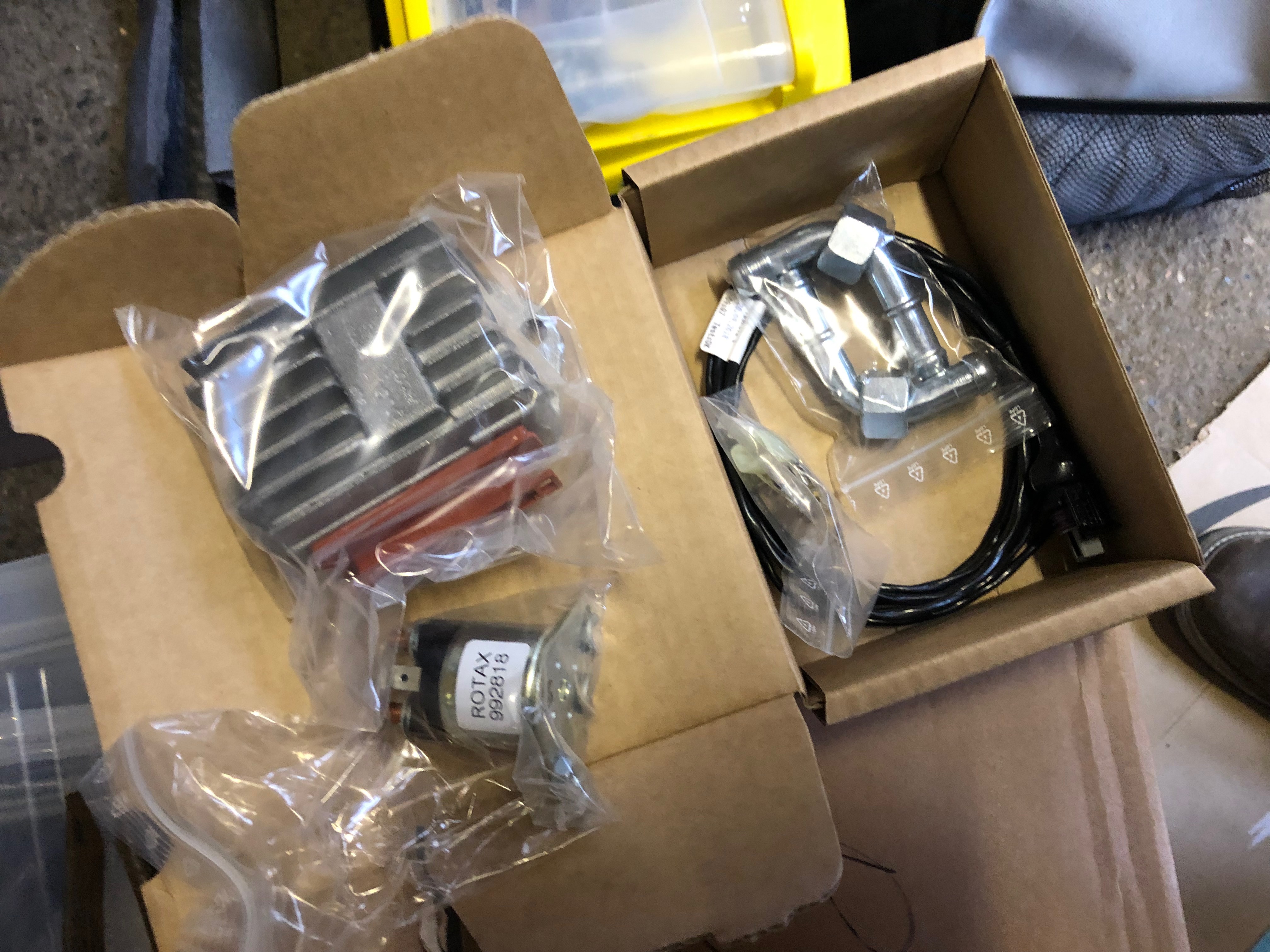
The missing parts arrived in the post today so I was able to get on with some of the tasks that have been stalled.
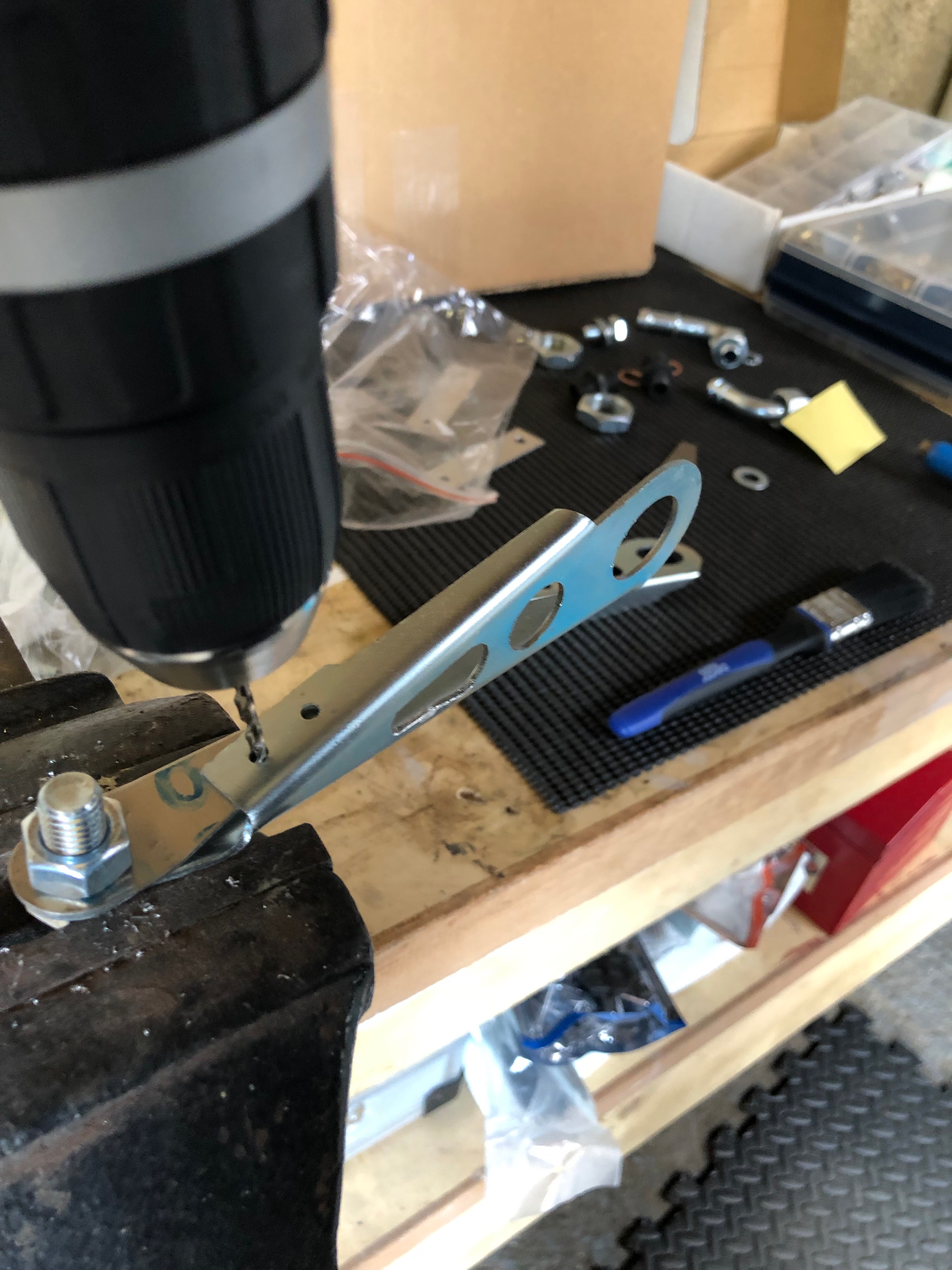
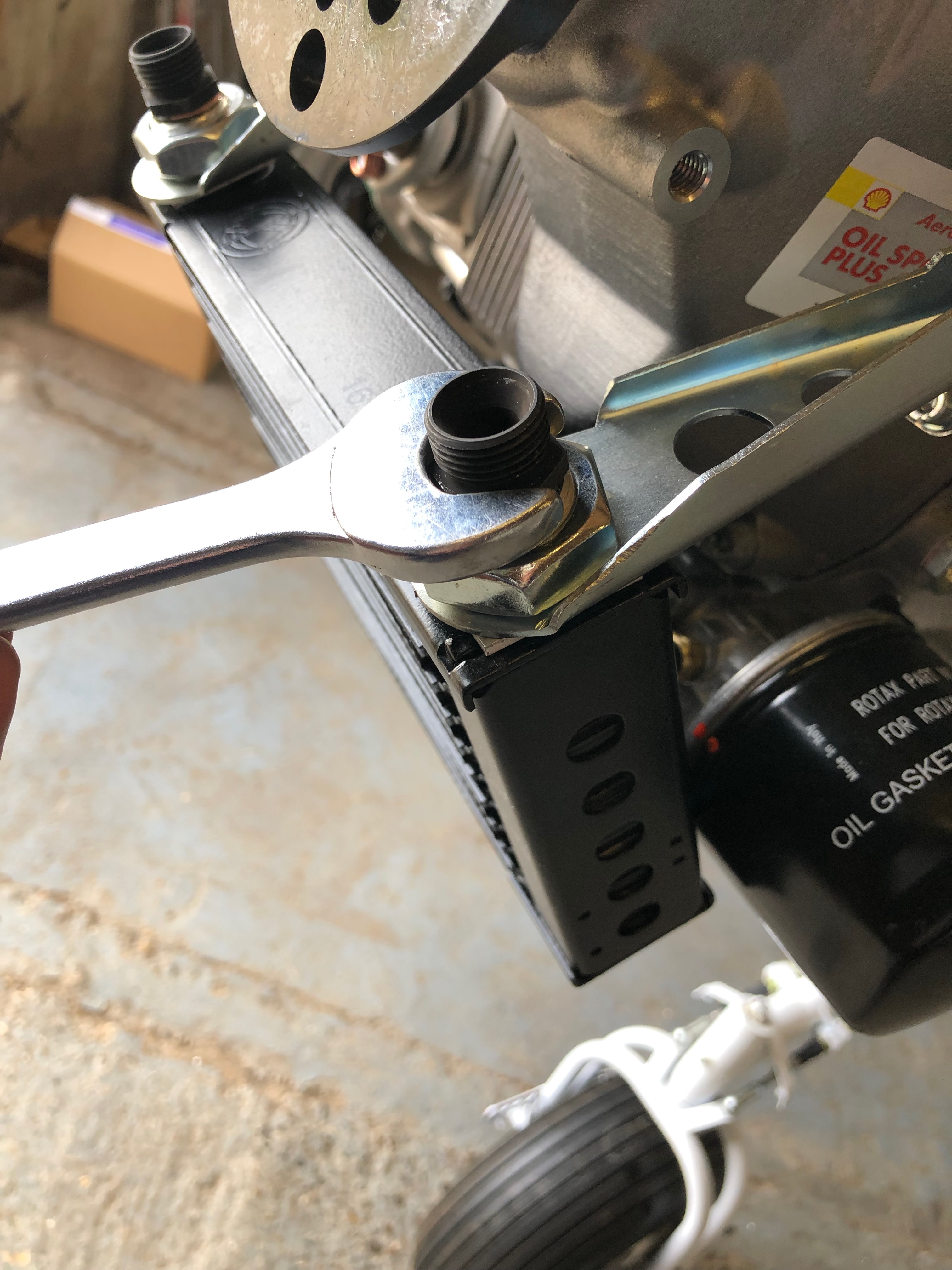
First job today is to add strengthening to the oil coolers bracket. The strip of metal is bolted to the bracket and holes are drilled to accept 2 rivets.
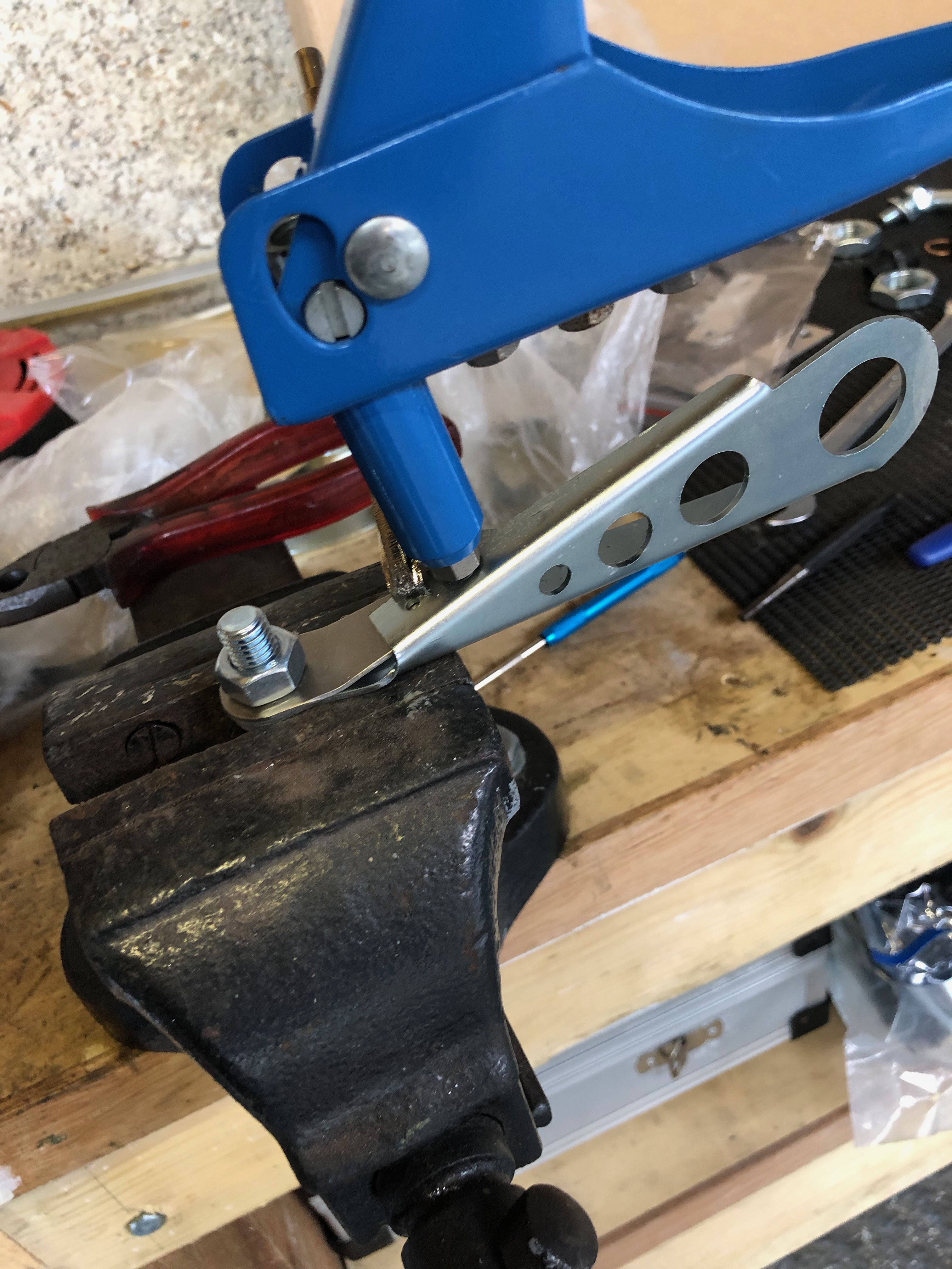
Rivets are installed.
The finished brackets ready for install.
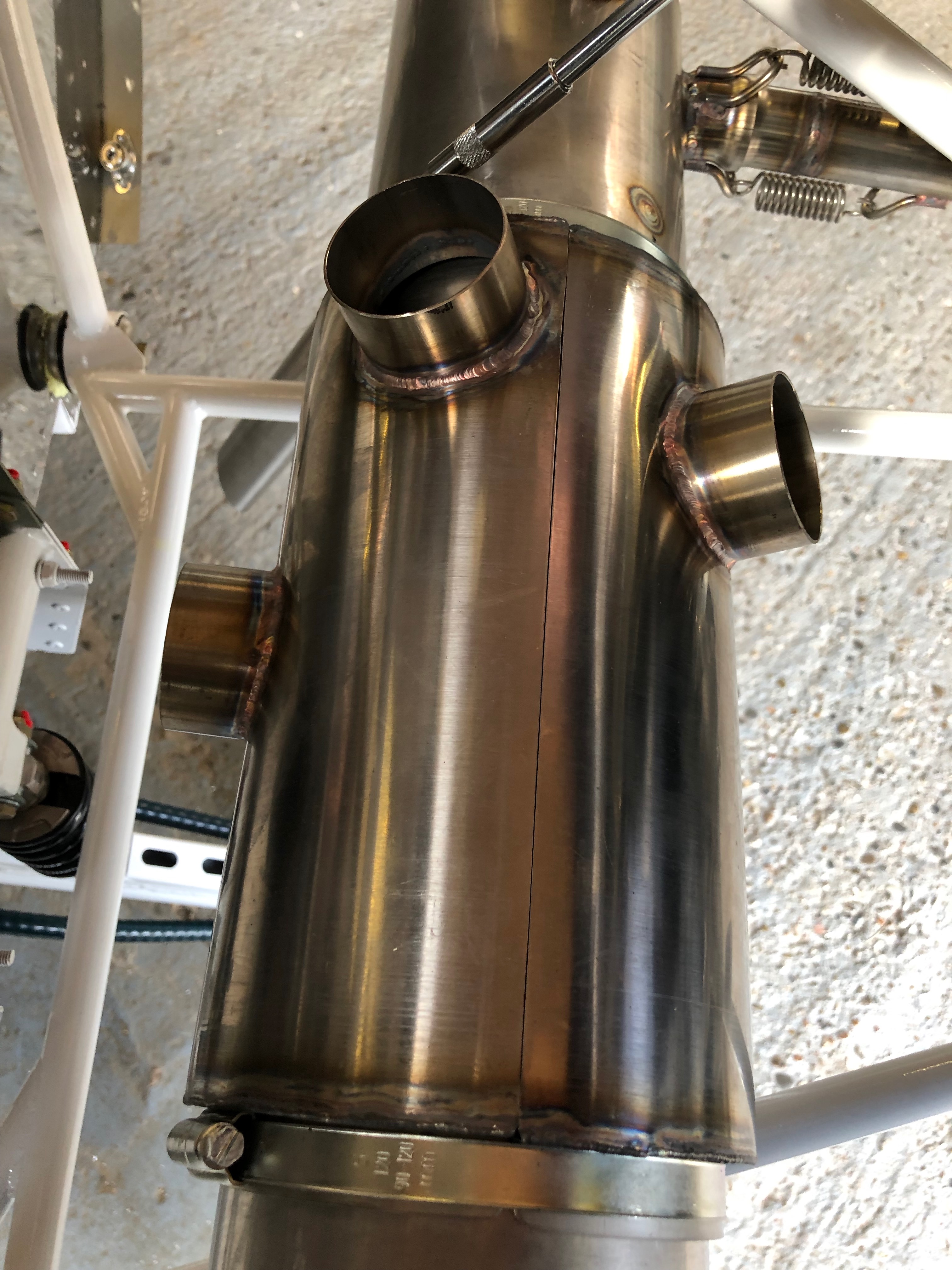
Next is to clamp the heat exchanger, for cabin and carb heat, onto the exhaust with large jubilee clips. They are no tightened at this point as it may need to be rotated later.
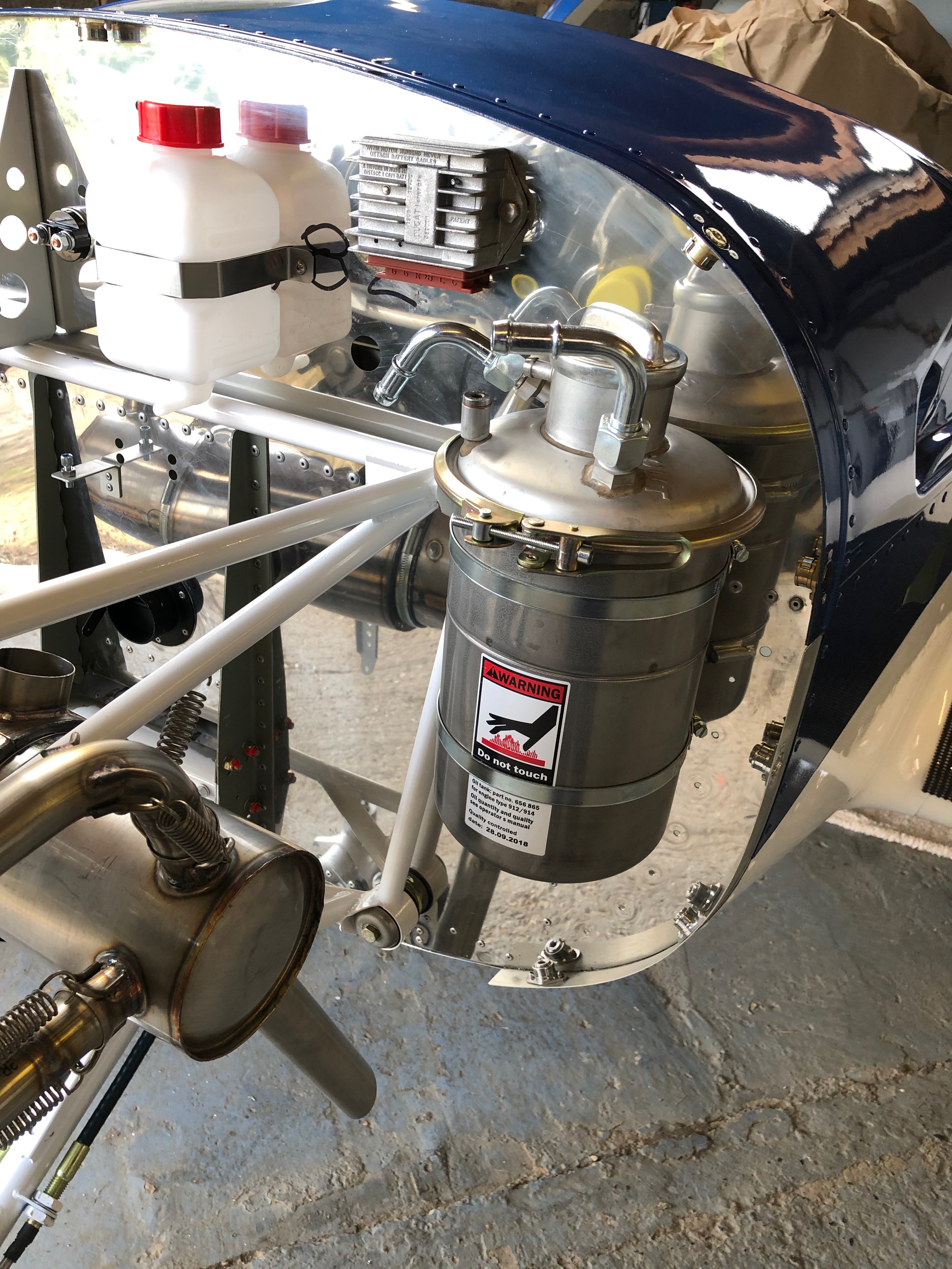
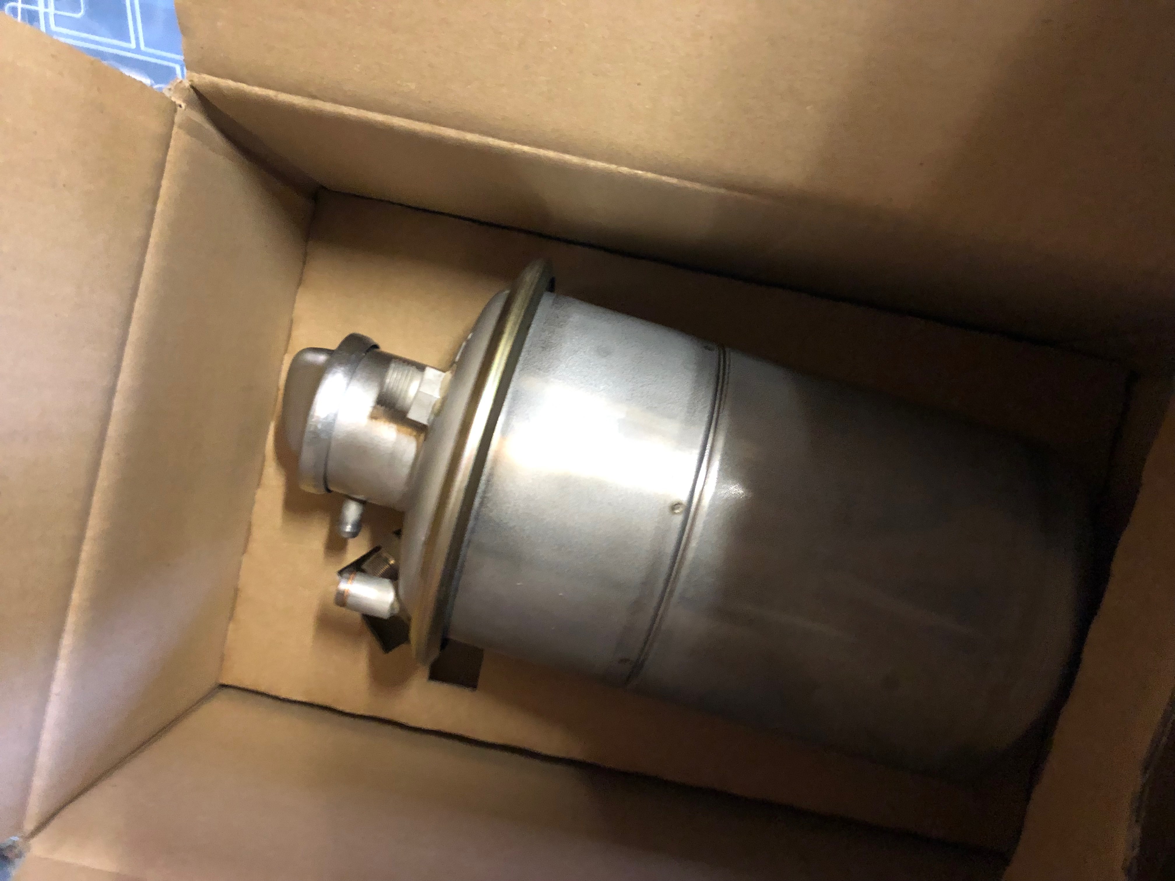
The oil tank is secured with large jubilee clips. Thinking about the location of the screw clamps I decided to turn them round.
Tank now install and the screw clamps are now ‘hidden’ at the rear of the tank. I’ve also turned the tank clamp around which makes it easier to undo for servicing.
Now the oil cooler brackets have been strengthened it’s time to install the oil cooler.
A reducer is installed to for the oil hose connectors.
Oil pipe connectors installed.
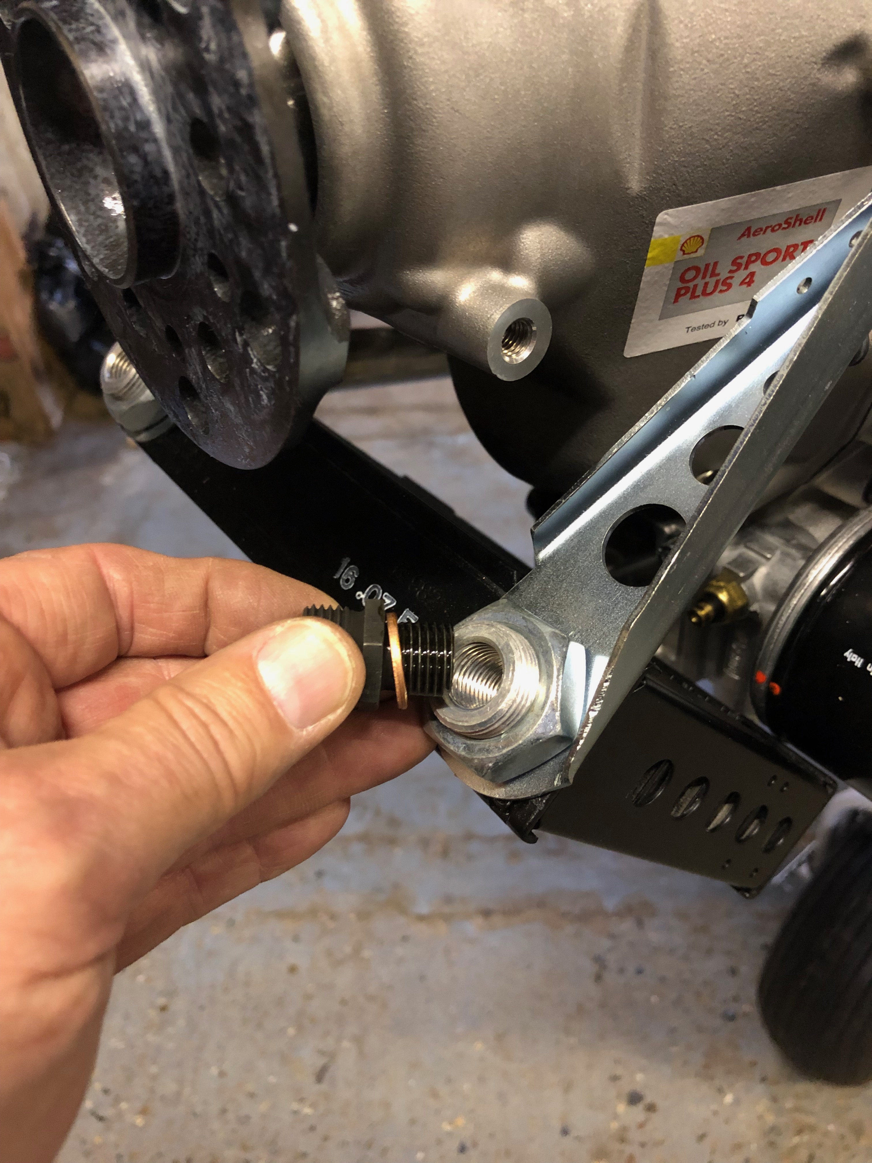
2 bolts are installed and locked with Loctite 243 to stop dirt and muck filling the lifting bracket mounts.
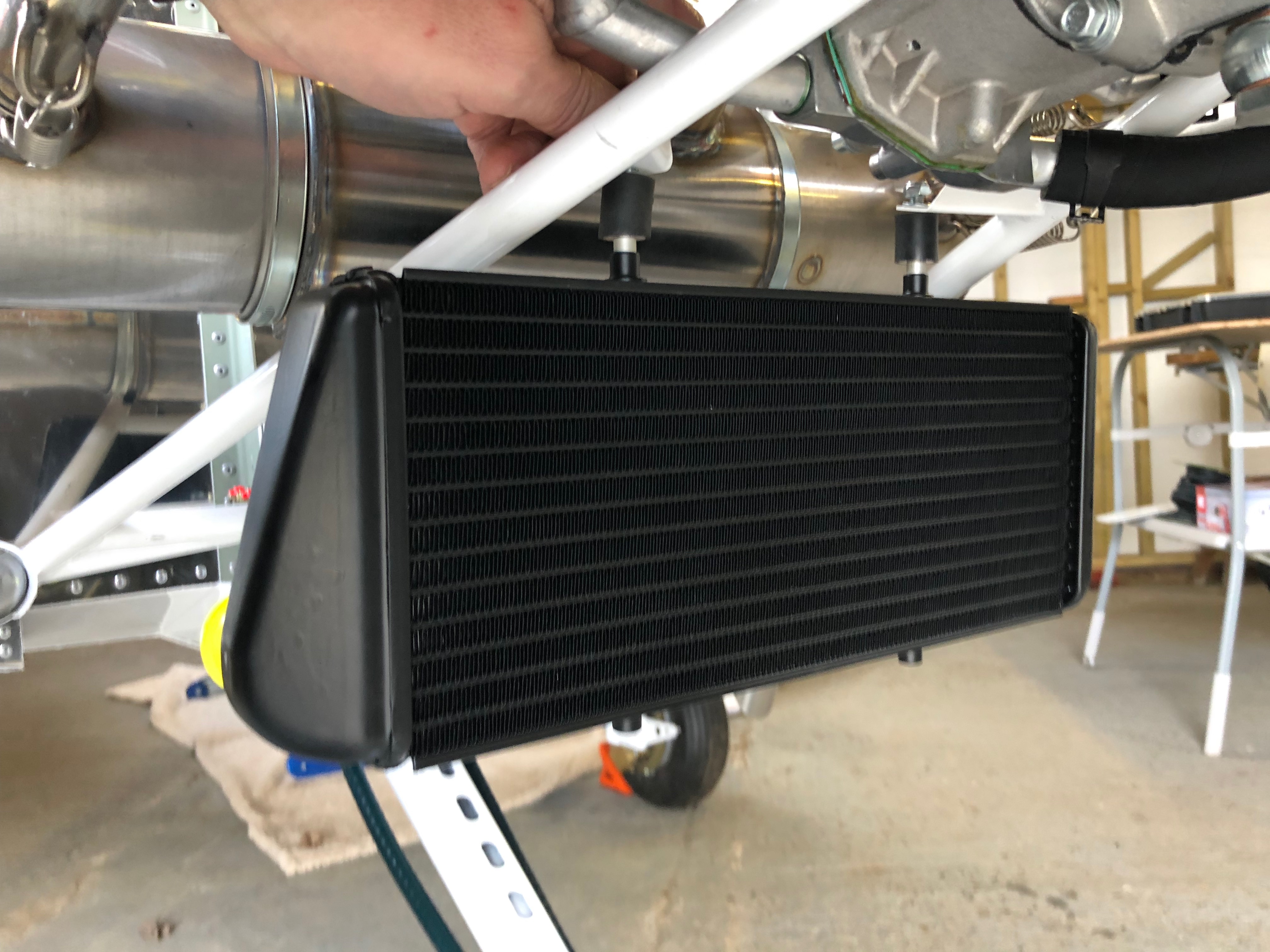
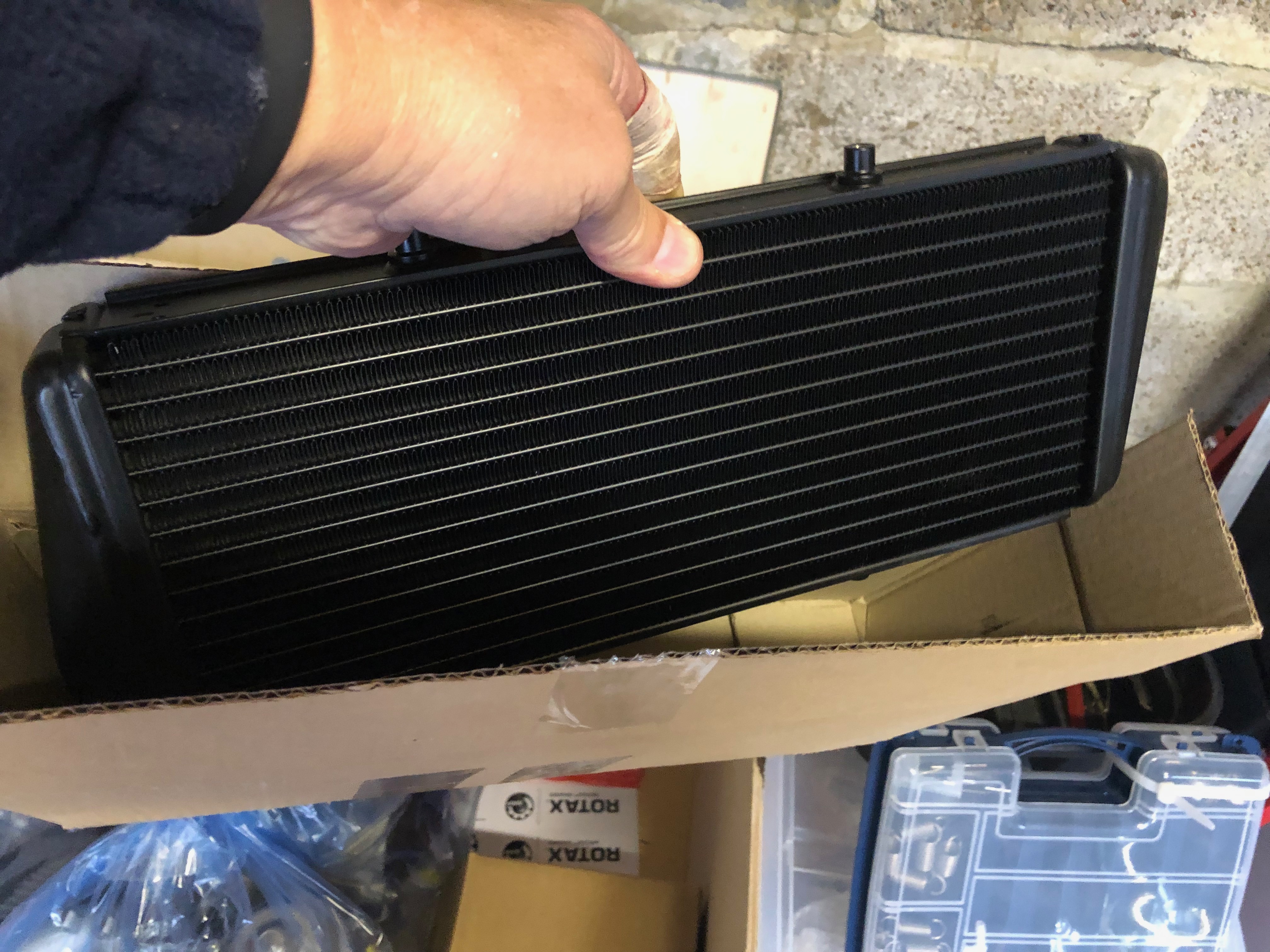
The water cooler is installed next and requires a couple of brackets and 5mm spacers to be made.
I think that’s close enough…
The 2 spacers are fitted on the rubber vibration isolators, screwed into the top of the water radiator and secured with 2 M6 nyloc nuts.
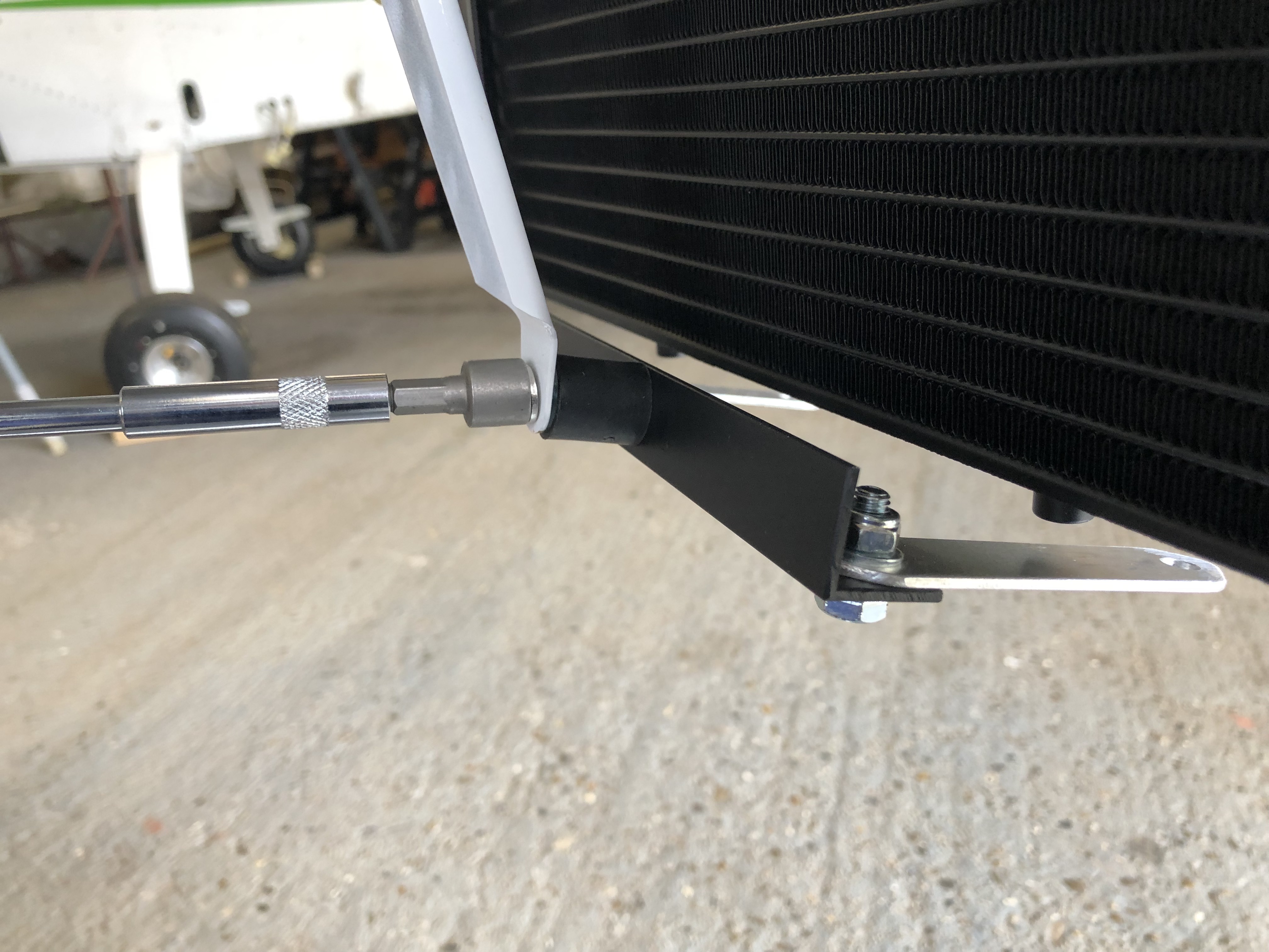
The aluminium brackets are fitted to the lower support…
and secured under the water radiator. I need to finish the final securing tomorrow.
Unfortunately because a number of items have been omitted from the kit, today is going to be mainly small jobs that can be done to allow other work to proceed when the bits turn up.
I will also start the fuel system install.
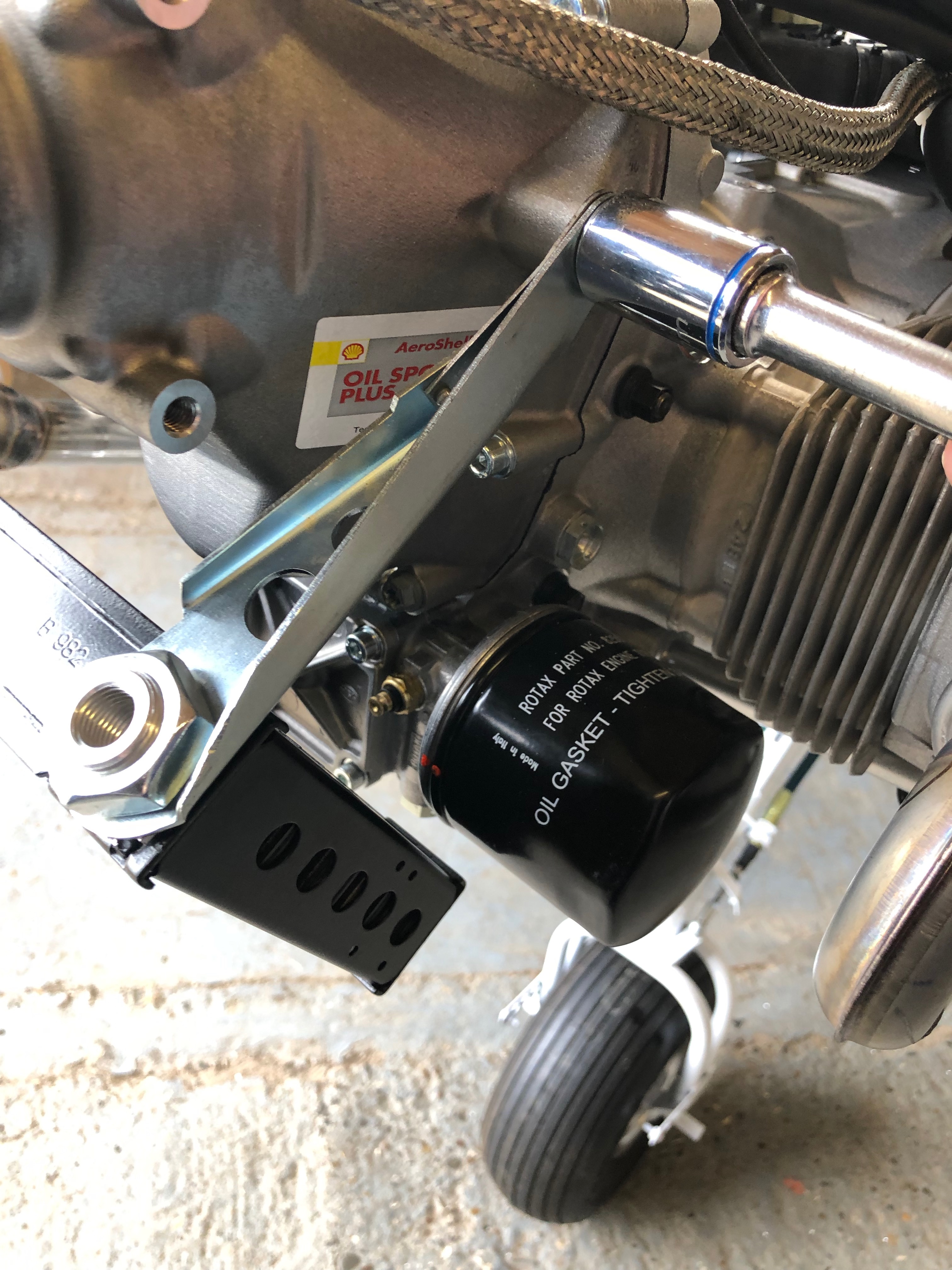
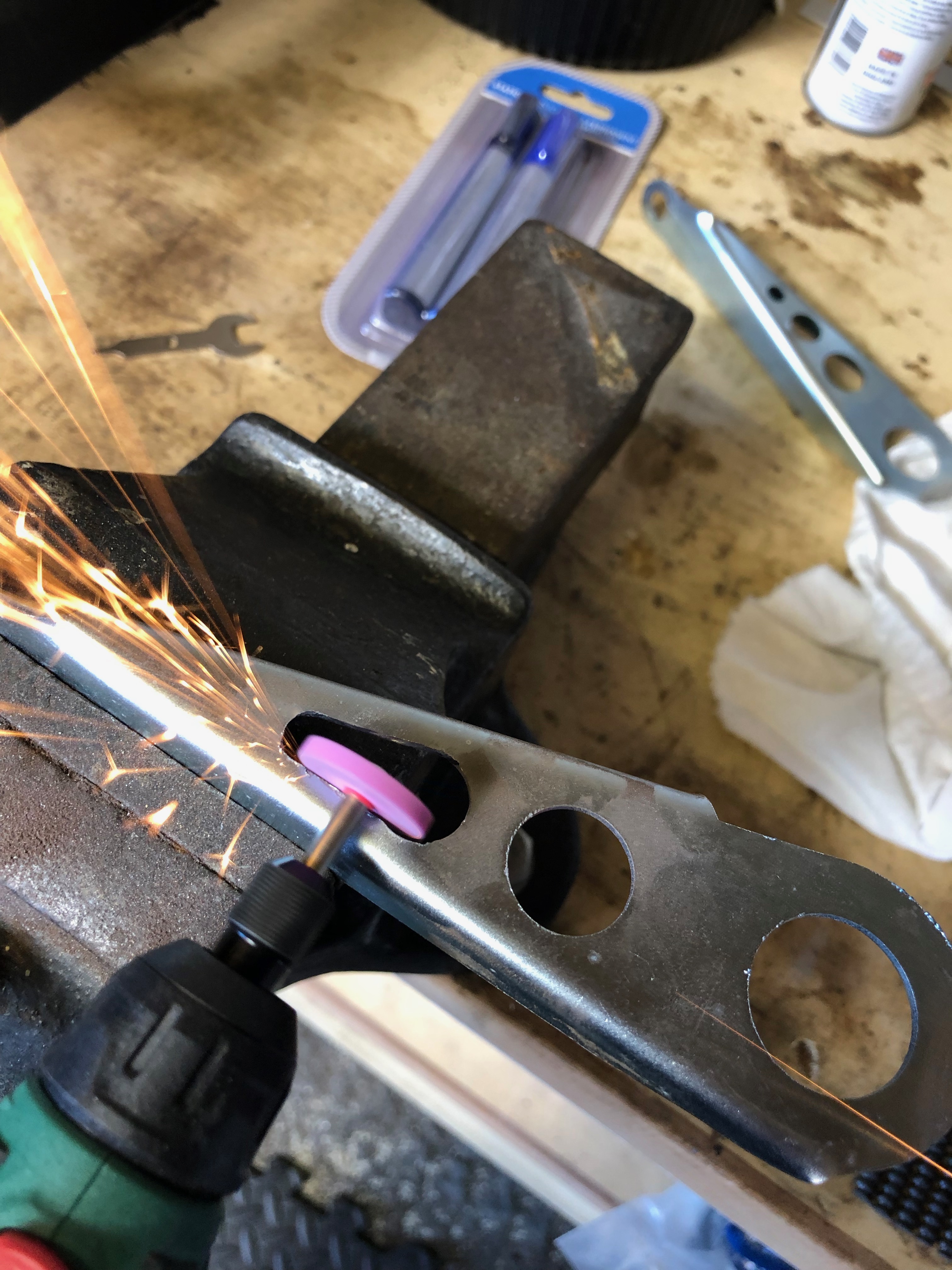
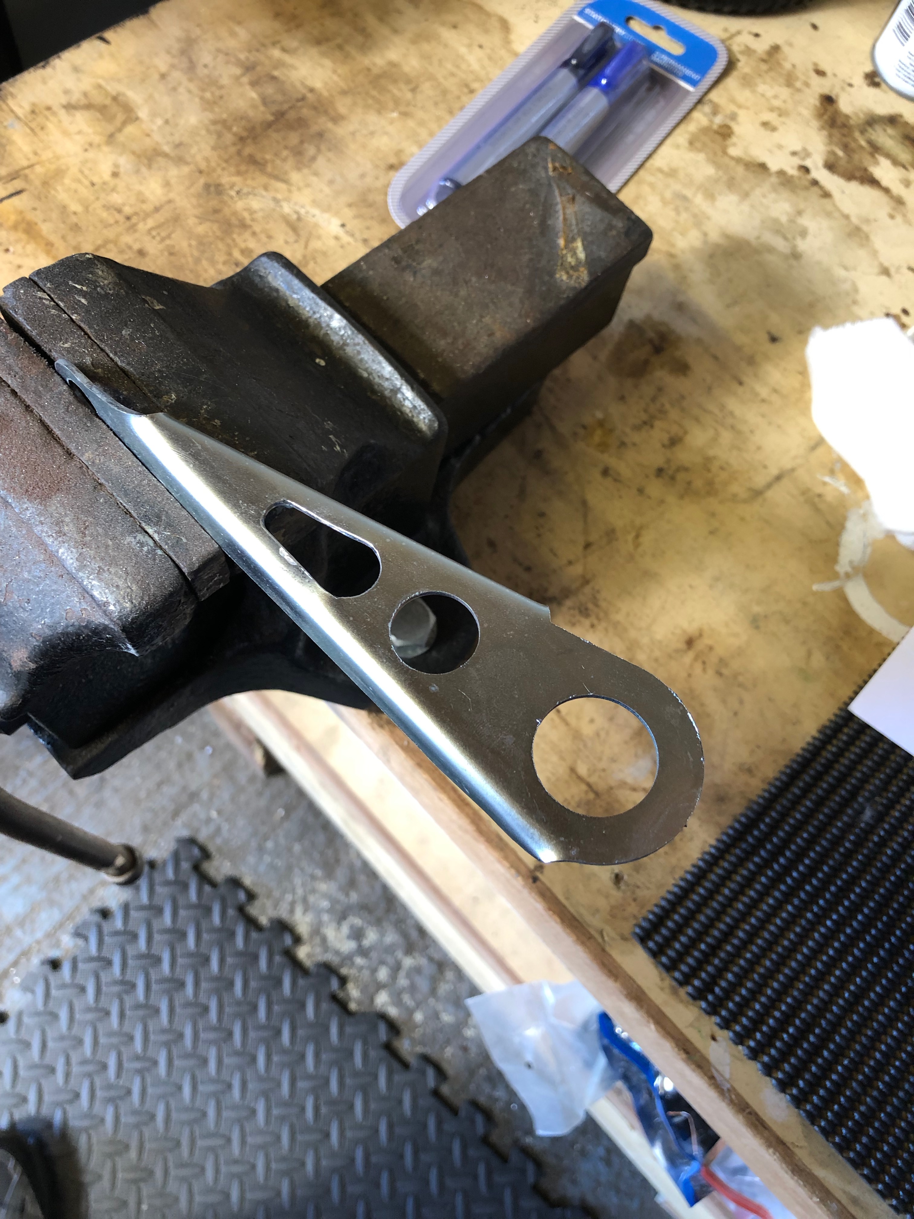
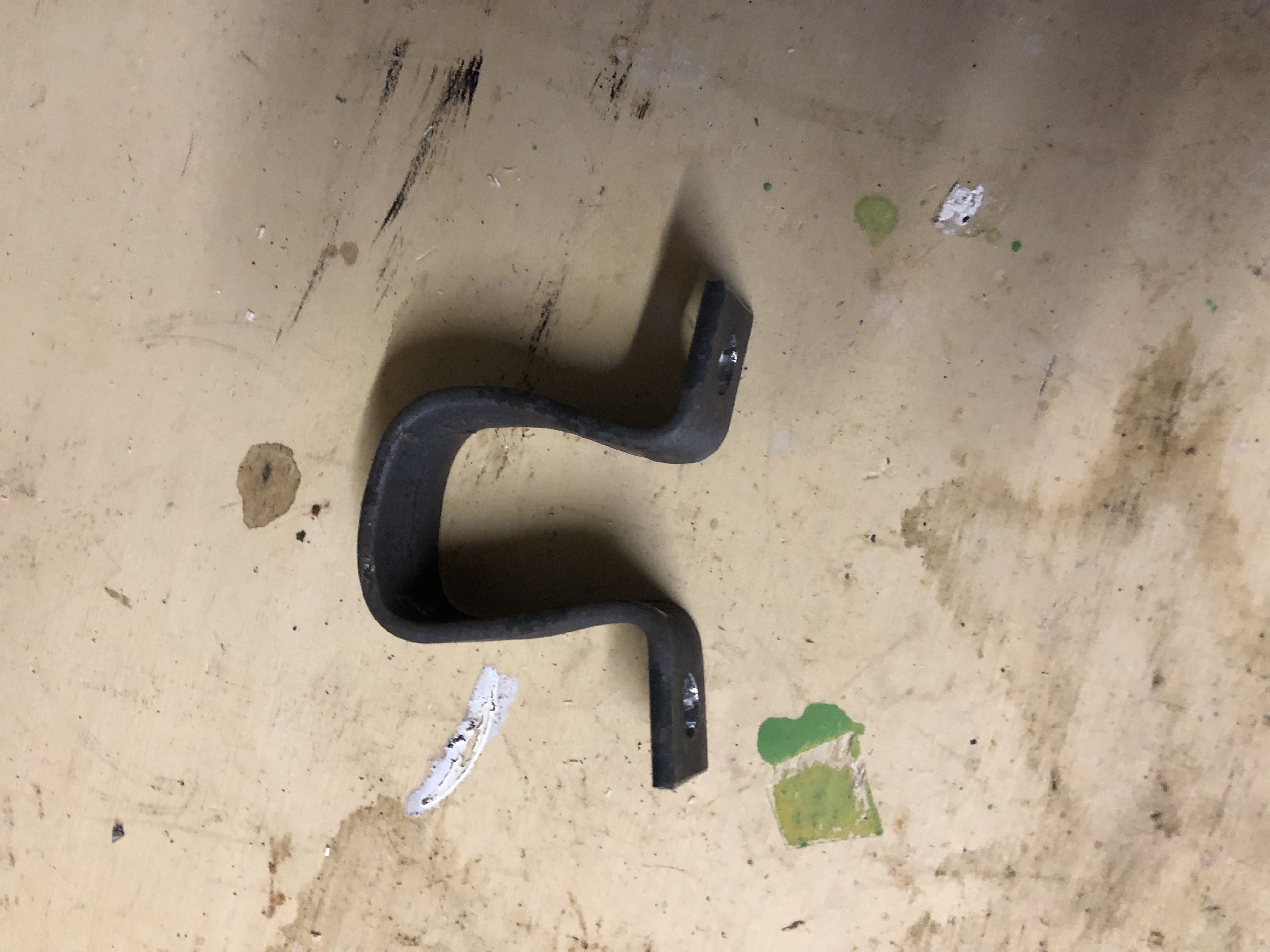
The oil radiator bracket needs to be modified to allow the mechanical fuel pump drain tube to pass through it.
Only the right bracket needs to be modified in this way but both need to be strengthened before they can be fitted. Unfortunately the strengtheners were missing so Tony is making some up and sending them in the post.
To give a visual indication of any loosening of the engine mount bolts Torque seal is applied across the nut and thread.
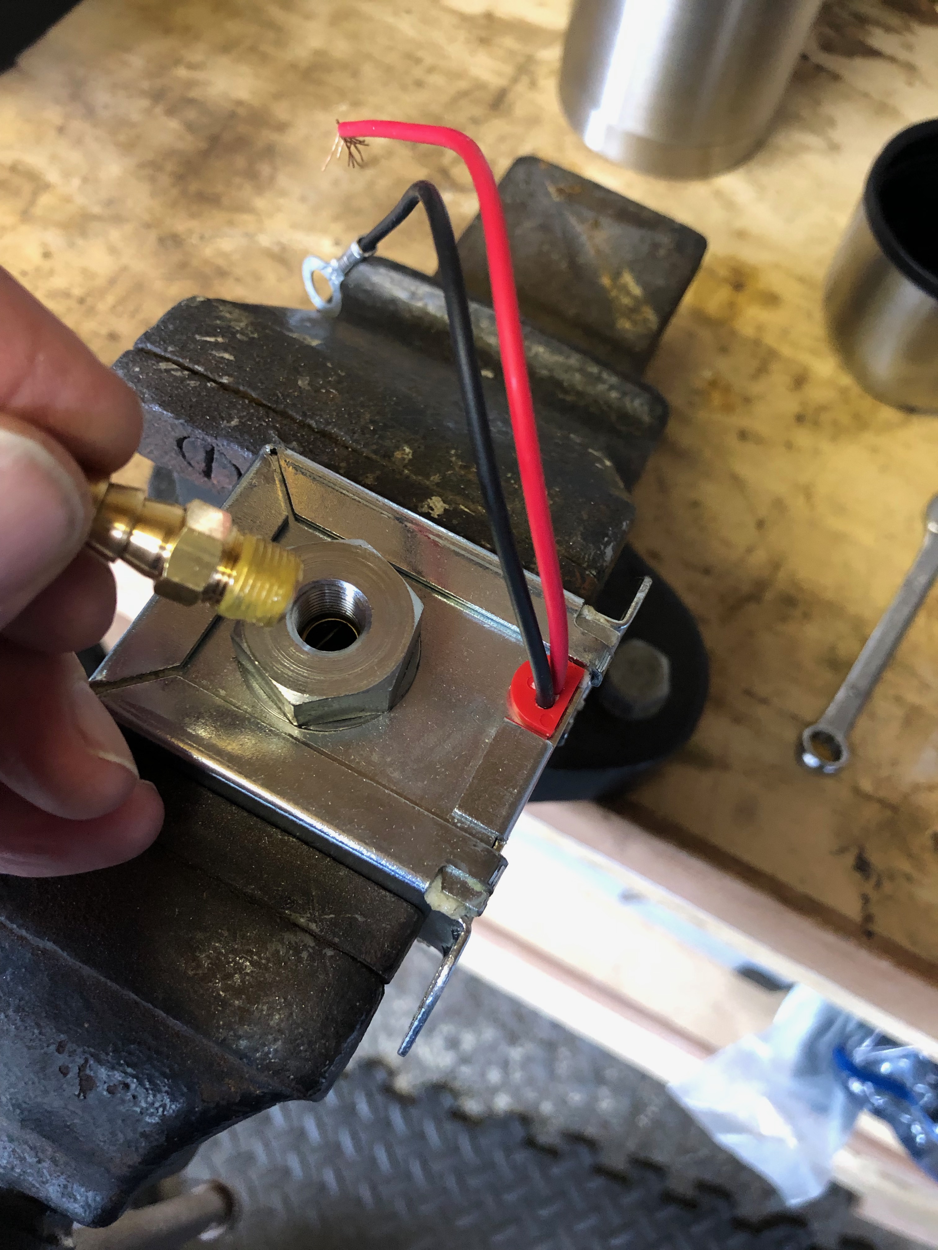
Loctite 577 is applied to the thread of the 8mm fitting before being screwed into the pump body.
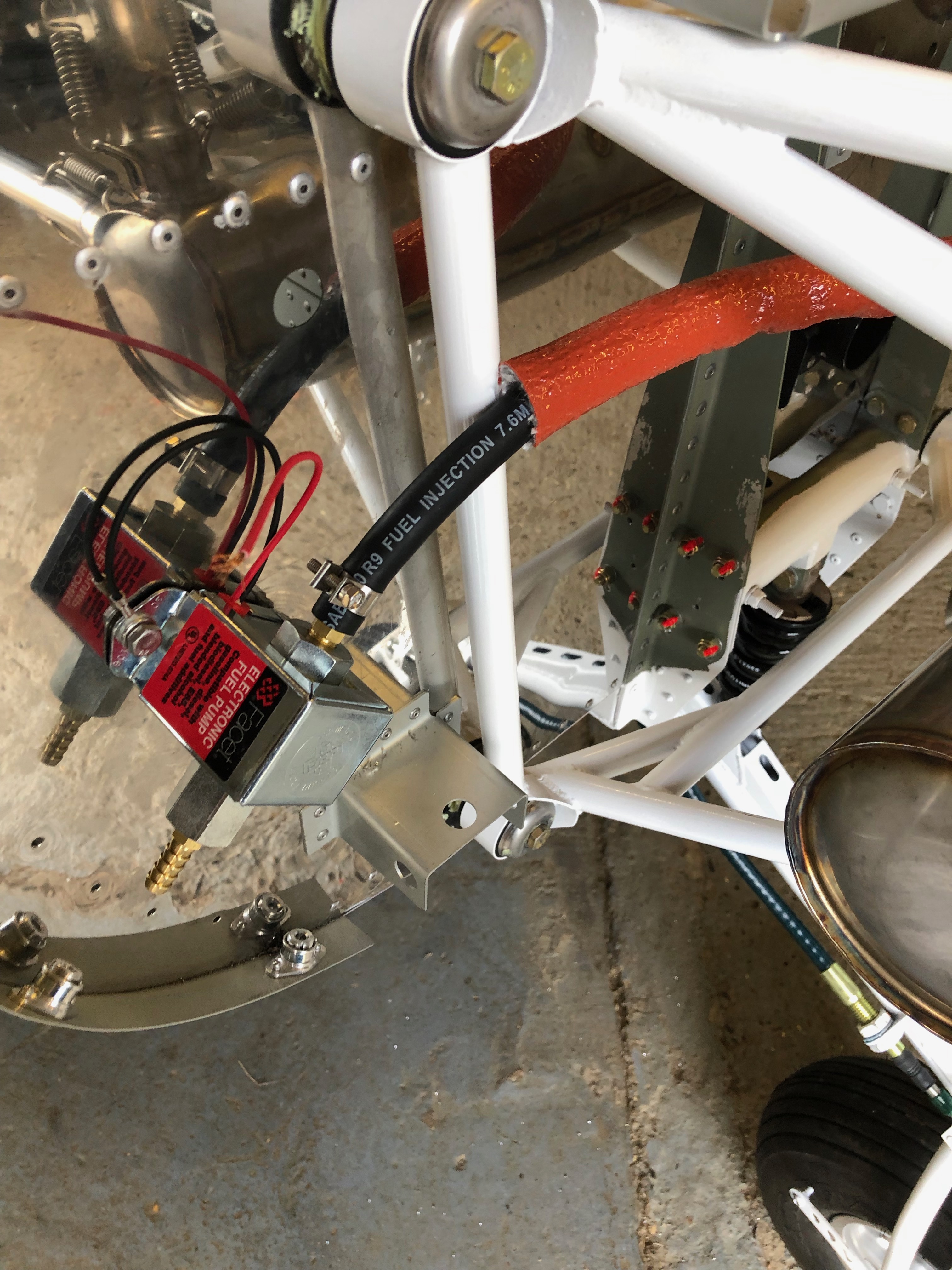
The firewall is marked and drilled. 2 x M6 Rivnuts are fitted before securing with M6 bolts.
The 8mm R9 fuel hose is attached and secured with hose clamps before fire sleeving is slid over.
The fire proof sleeving is secured using a wire wrap.
The fuel lines were missing from the kit so they are being made and sent to me.
A number of fittings are also missing so Tony is sending them to me by post.
The Gascolator and drain valve are on order from Andair.
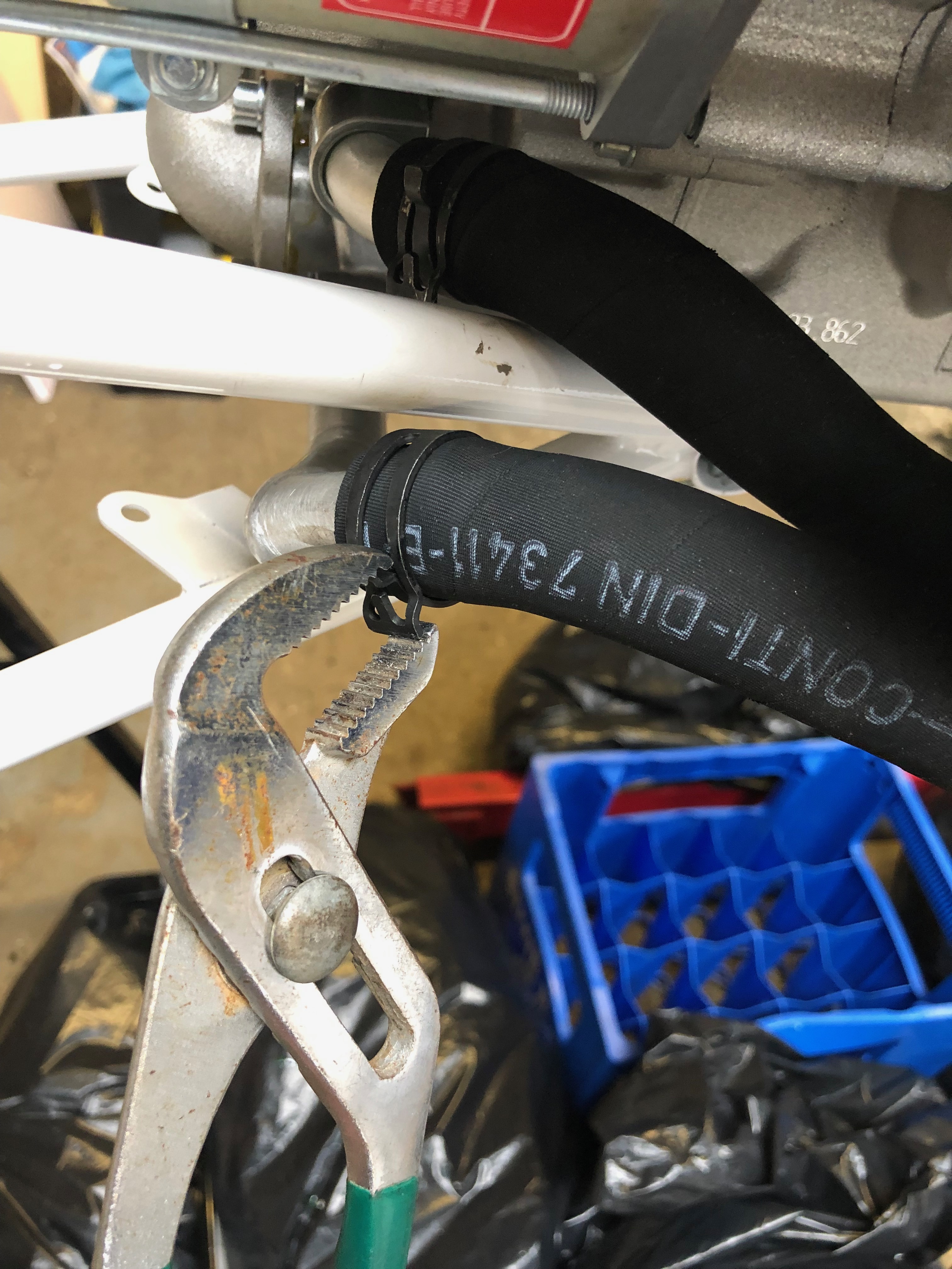
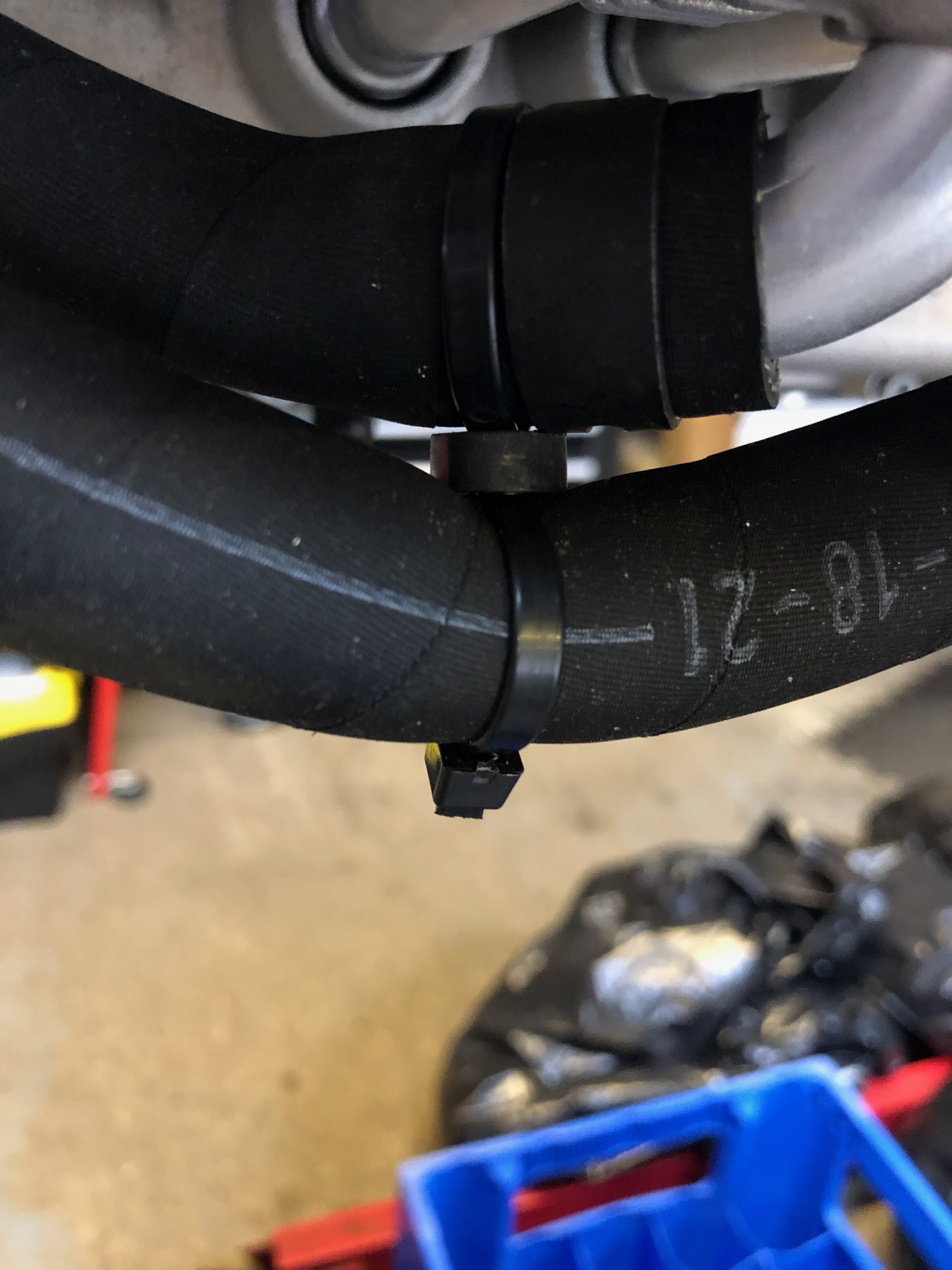
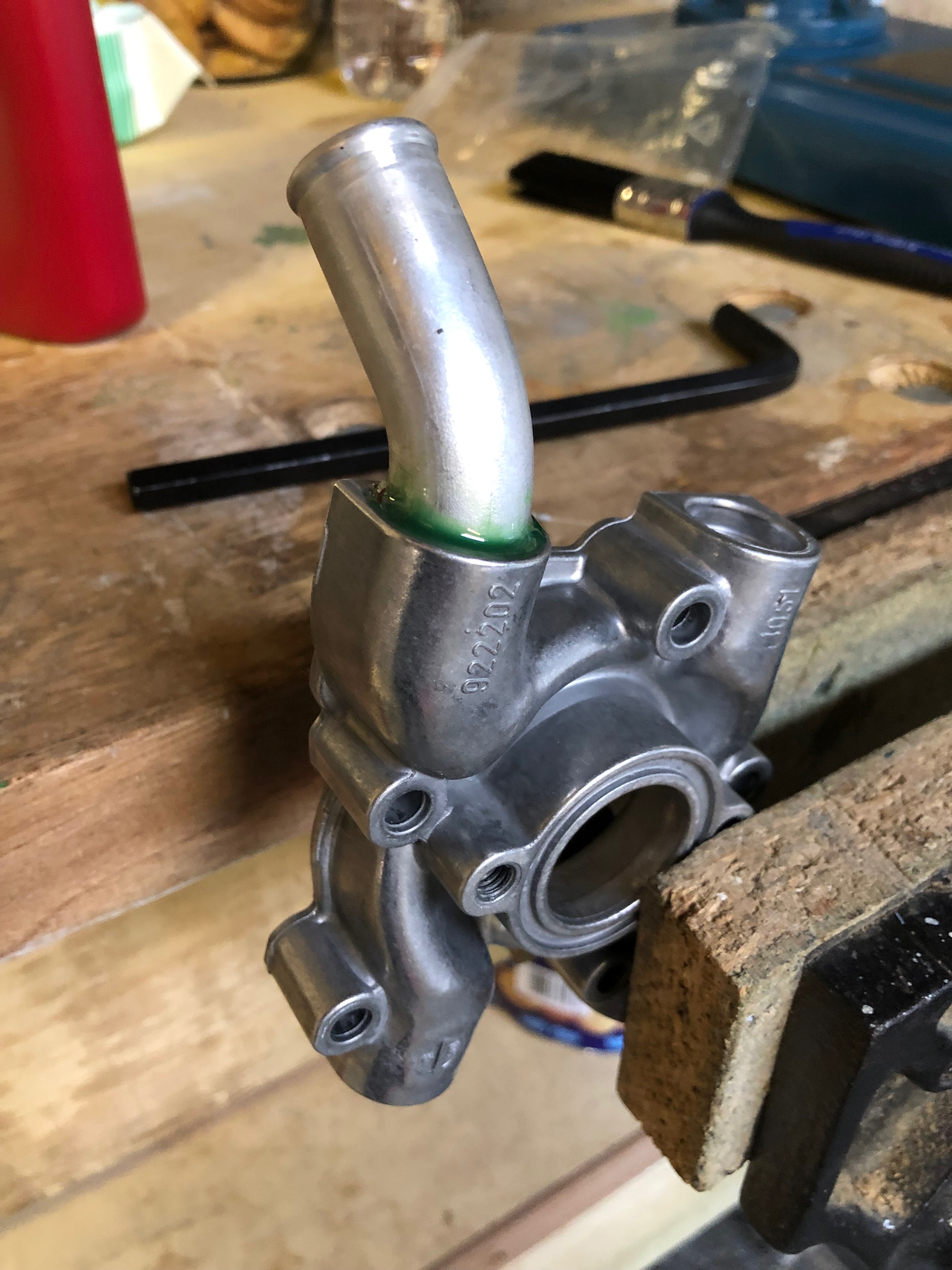
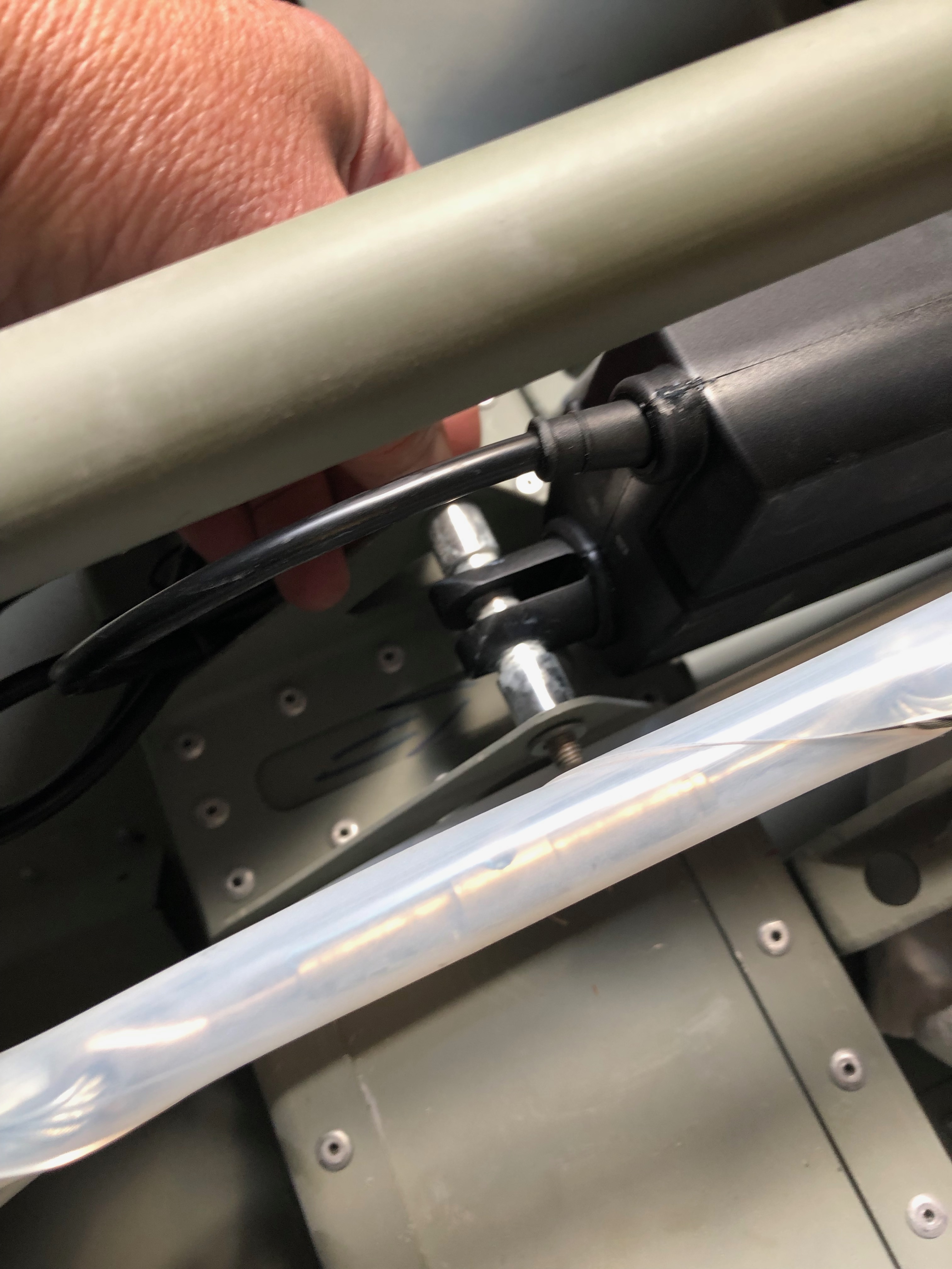
Now the Loctite is set the water pump pipes can be refitted.
A ‘stand off’ is required to stop these 2 pipes from rubbing.
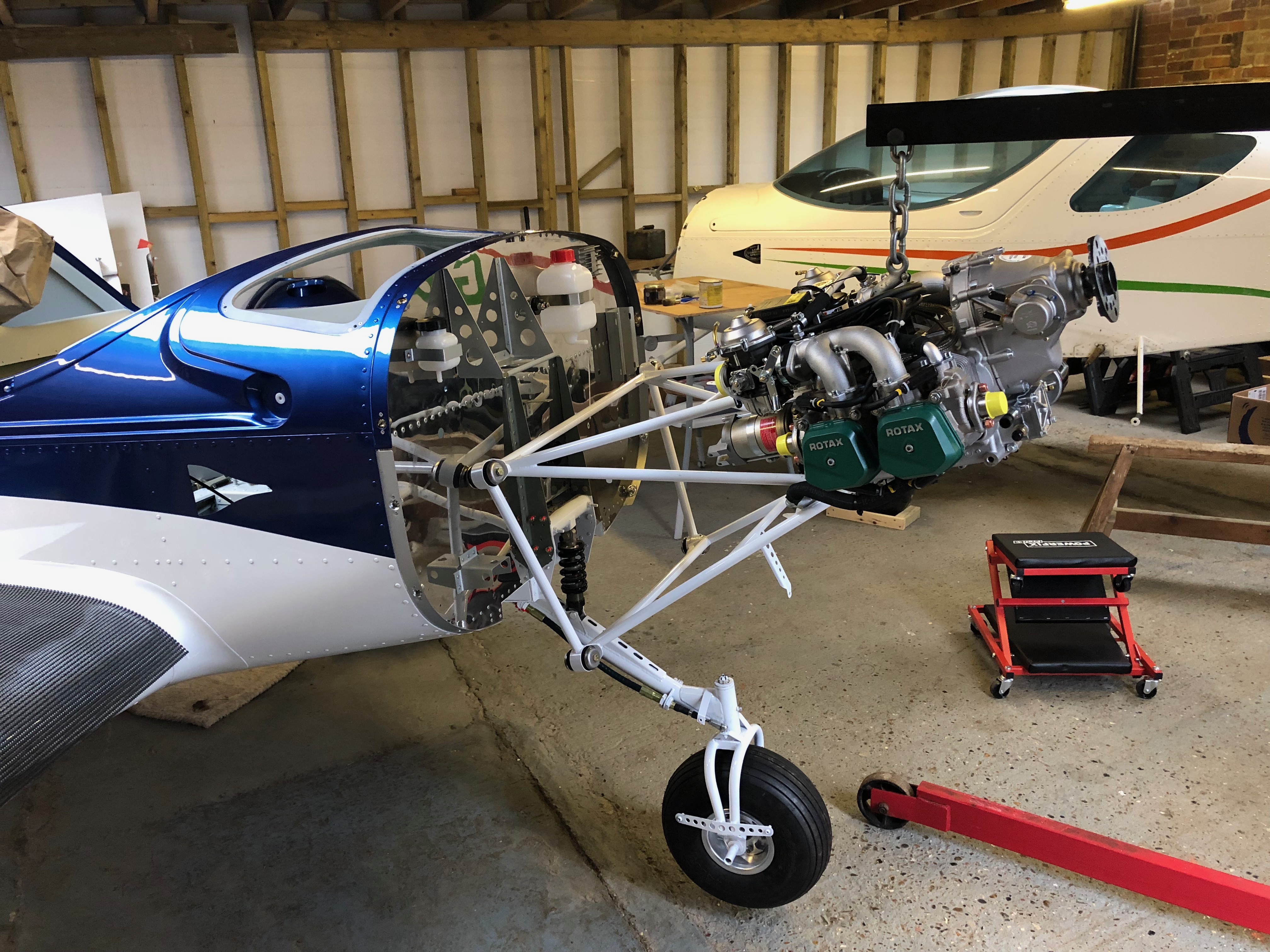
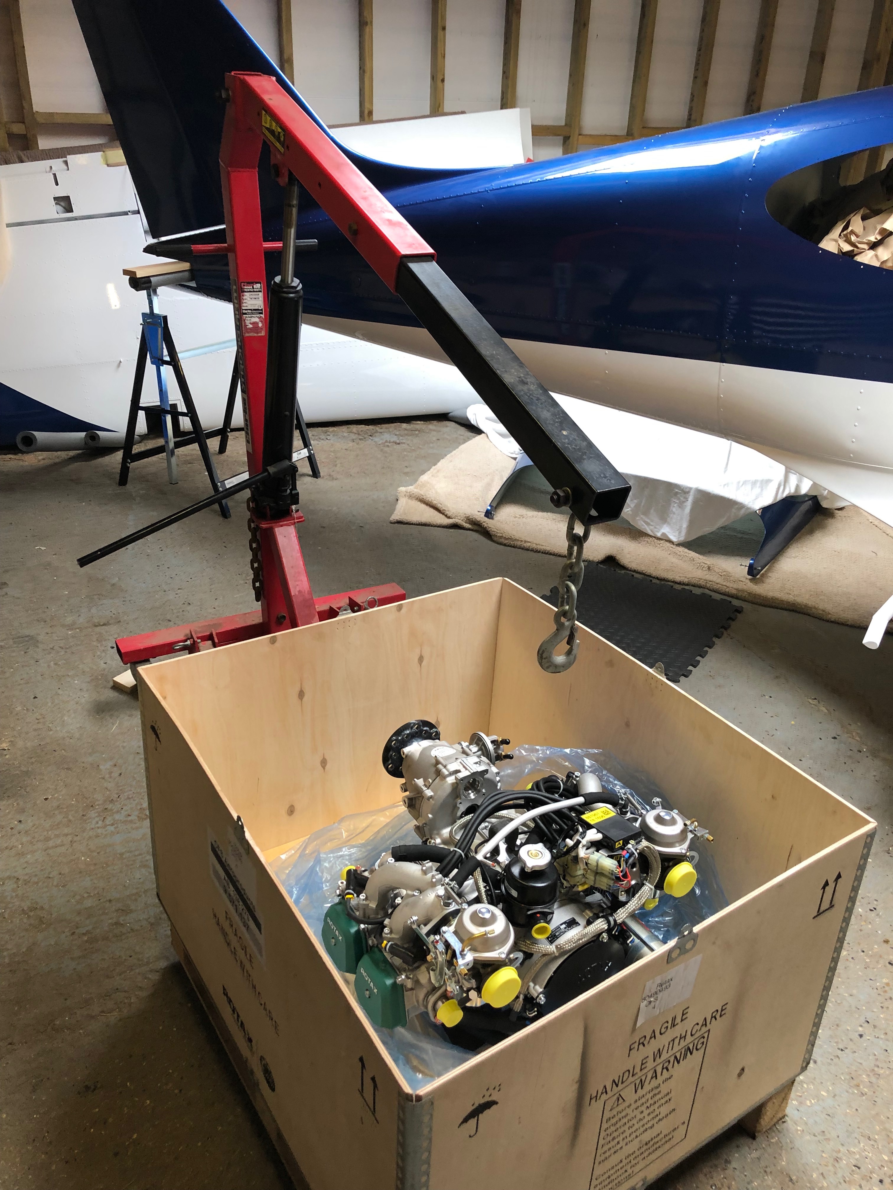
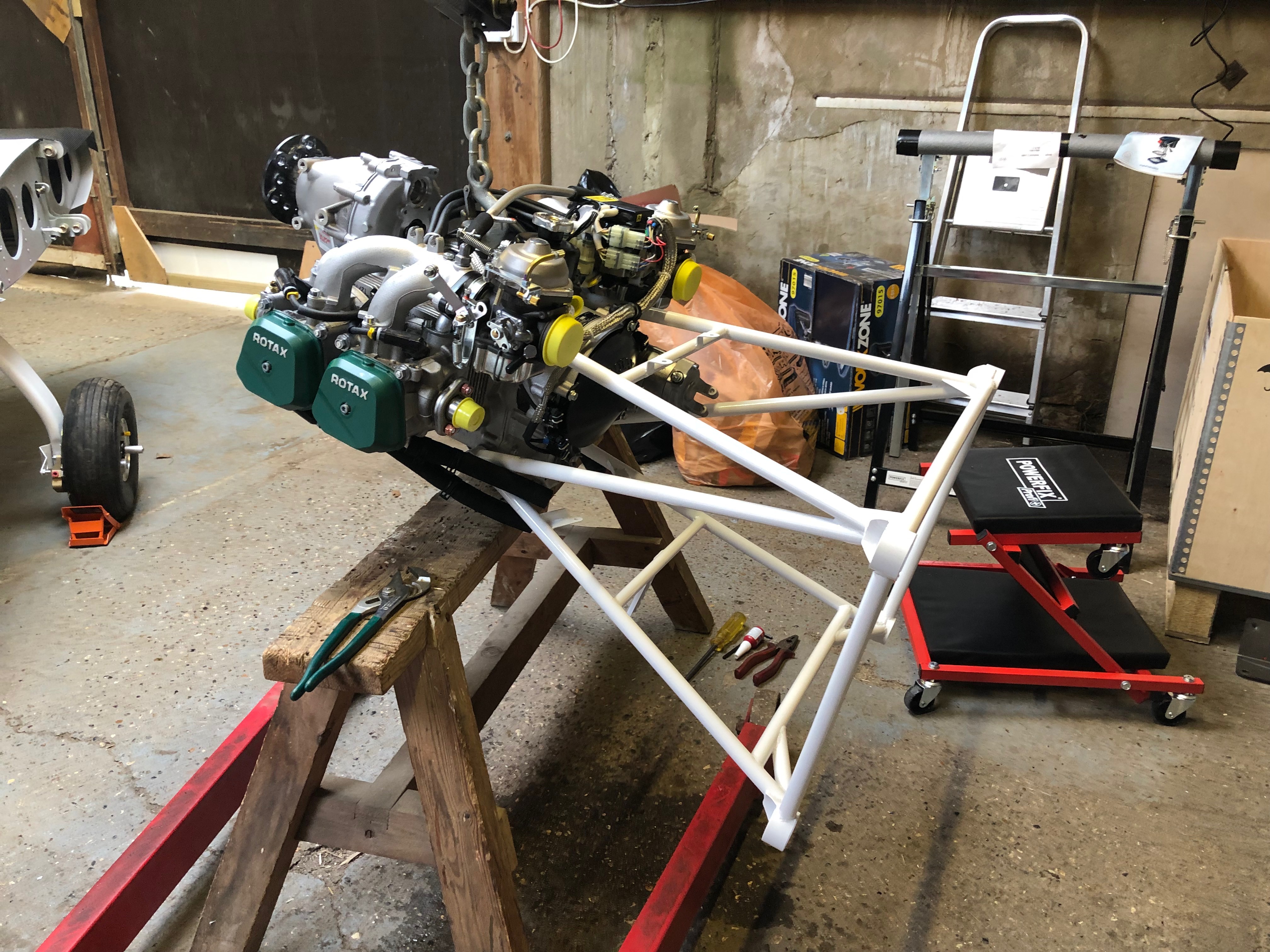
Time to hang the engine. The engine hoist and engine is positioned just in front of the fuselage and hoisted to roughly the correct height.
The engine mount steel cup washers are covered in jointing compound to stop them rusting once fitted.
First of 4 bolts to be fitted. 3 were quite easy to fit with the forth taking about 10 minutes to position properly as the rubber mount had turned slightly.
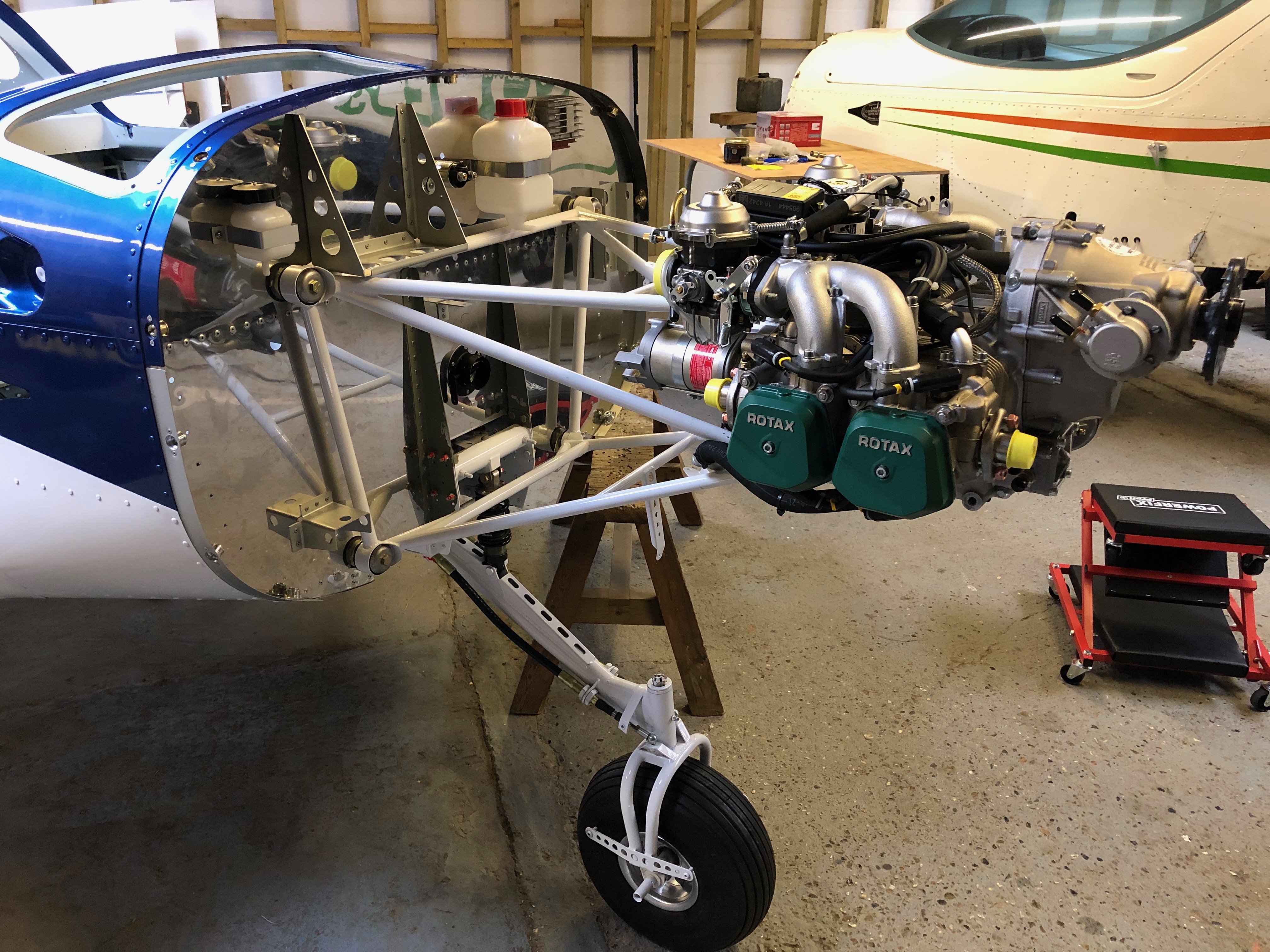
With the engine mounted and bolts tightened it’s time to fit the exhaust system.
The bespoke Bristell exhaust downpipes are fitted first.
The exhaust box is hung using springs and flexible couplings to provide a leak free system.
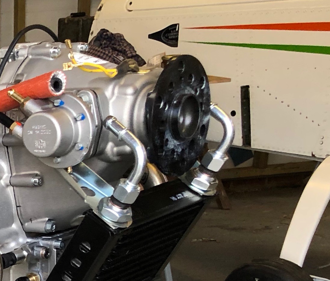
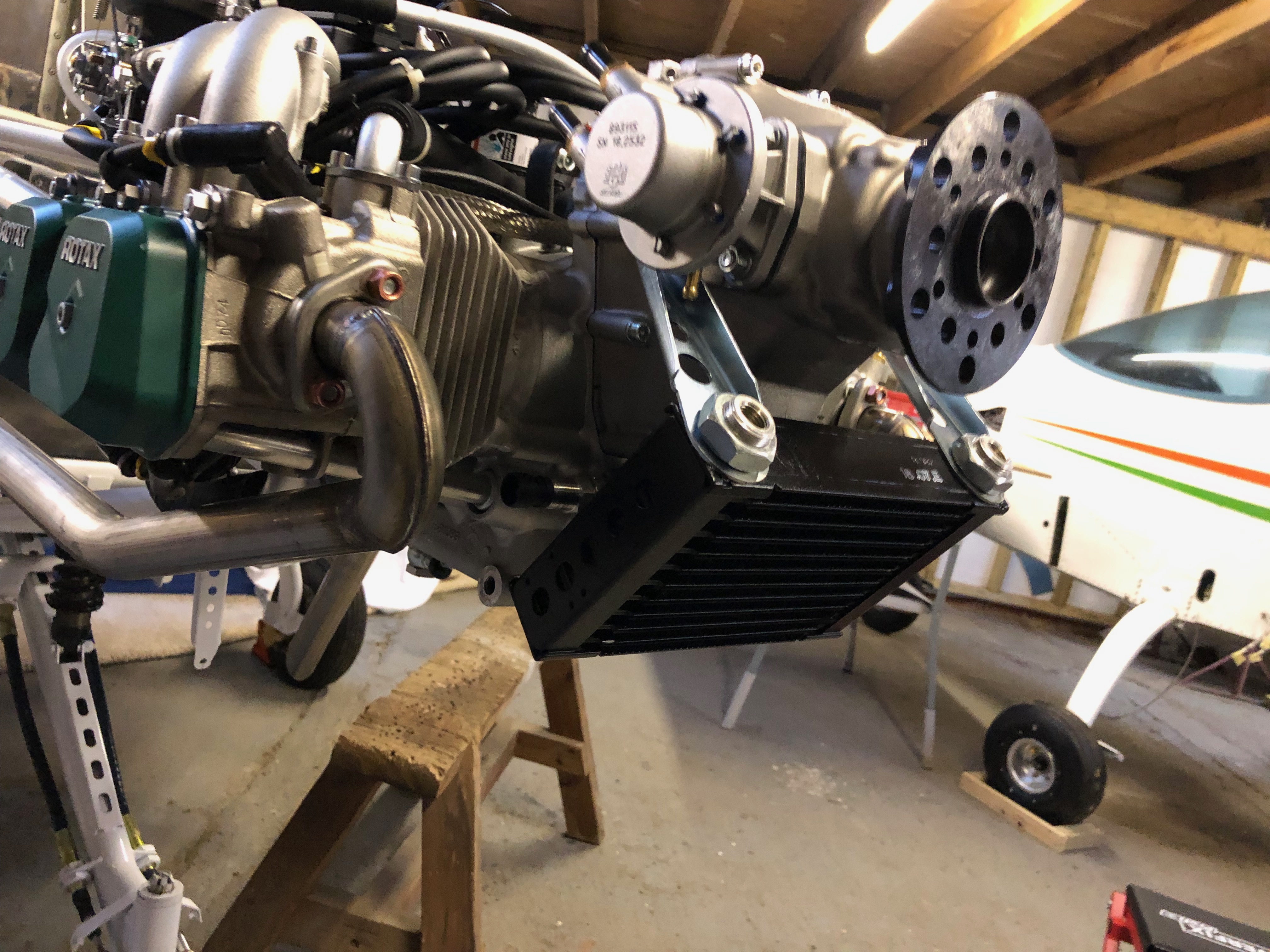
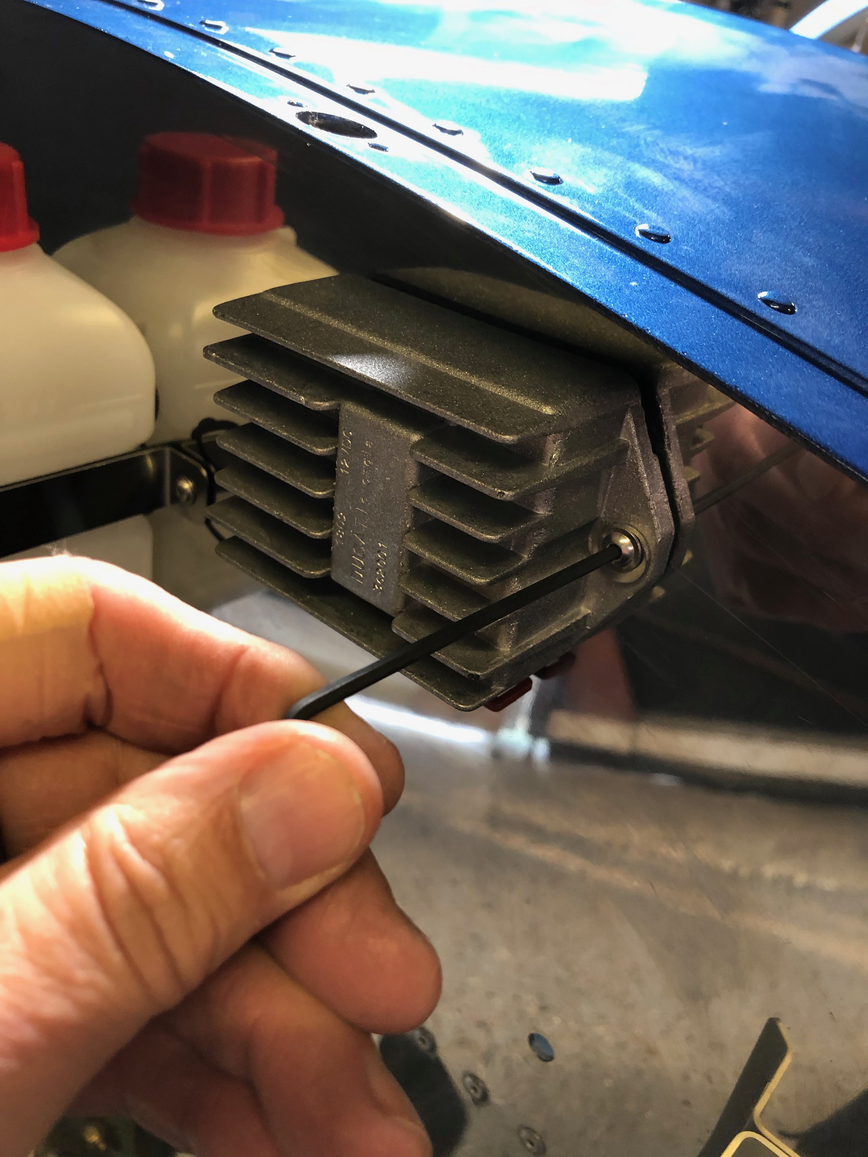
Next the oil cooler is fitted using the brackets provided.
and adapters are fitted to accept the aluminium connector pipes.
Good progress for the day. A tidy up of the workshop in readiness for tomorrow.
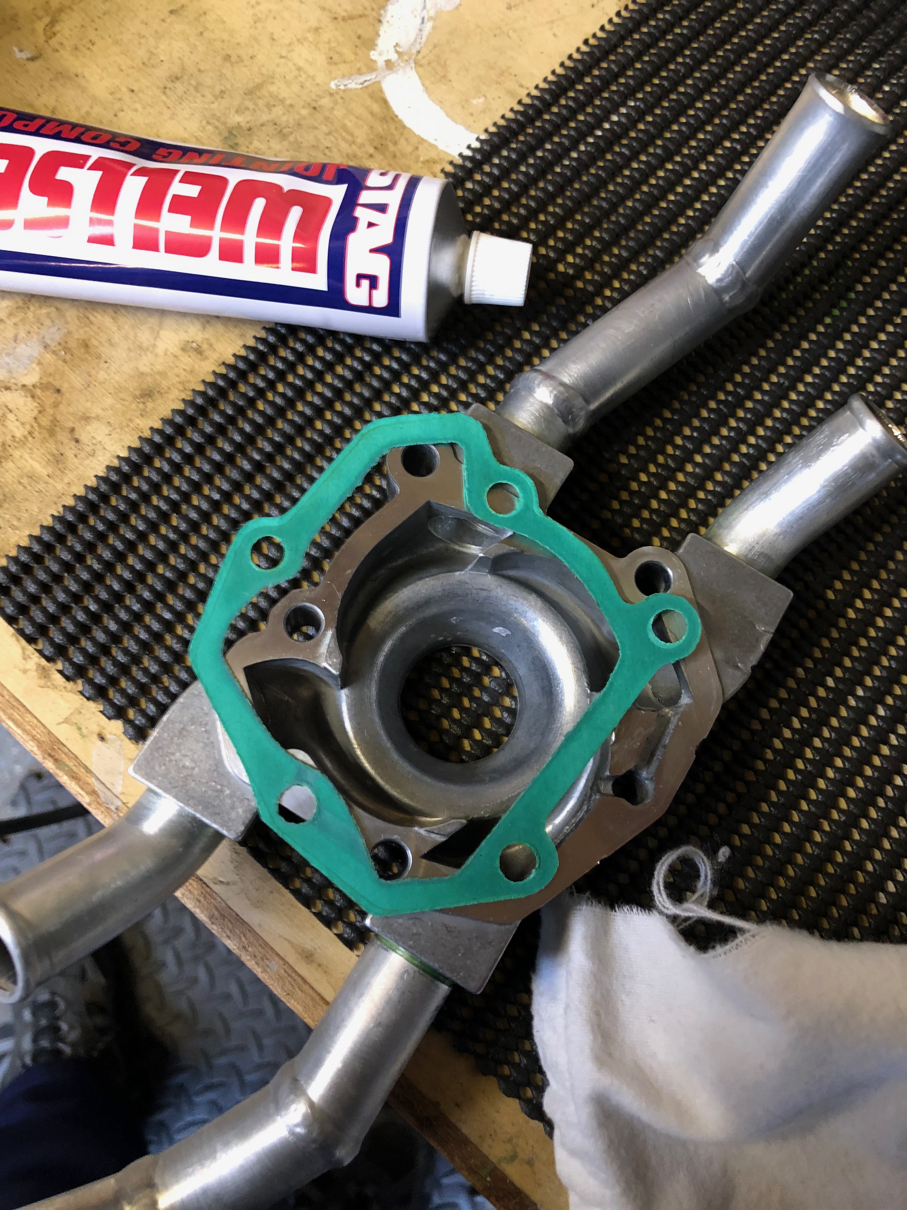
Now the Loctite has set the pump can be rebuilt, The mating faces and gasket were degreased and Wellseal applied, left to set before being reassembled.
The impeller cover seal is also refitted after a bead of Wellseal is applied. All bolts were then tightened to the correct torque.
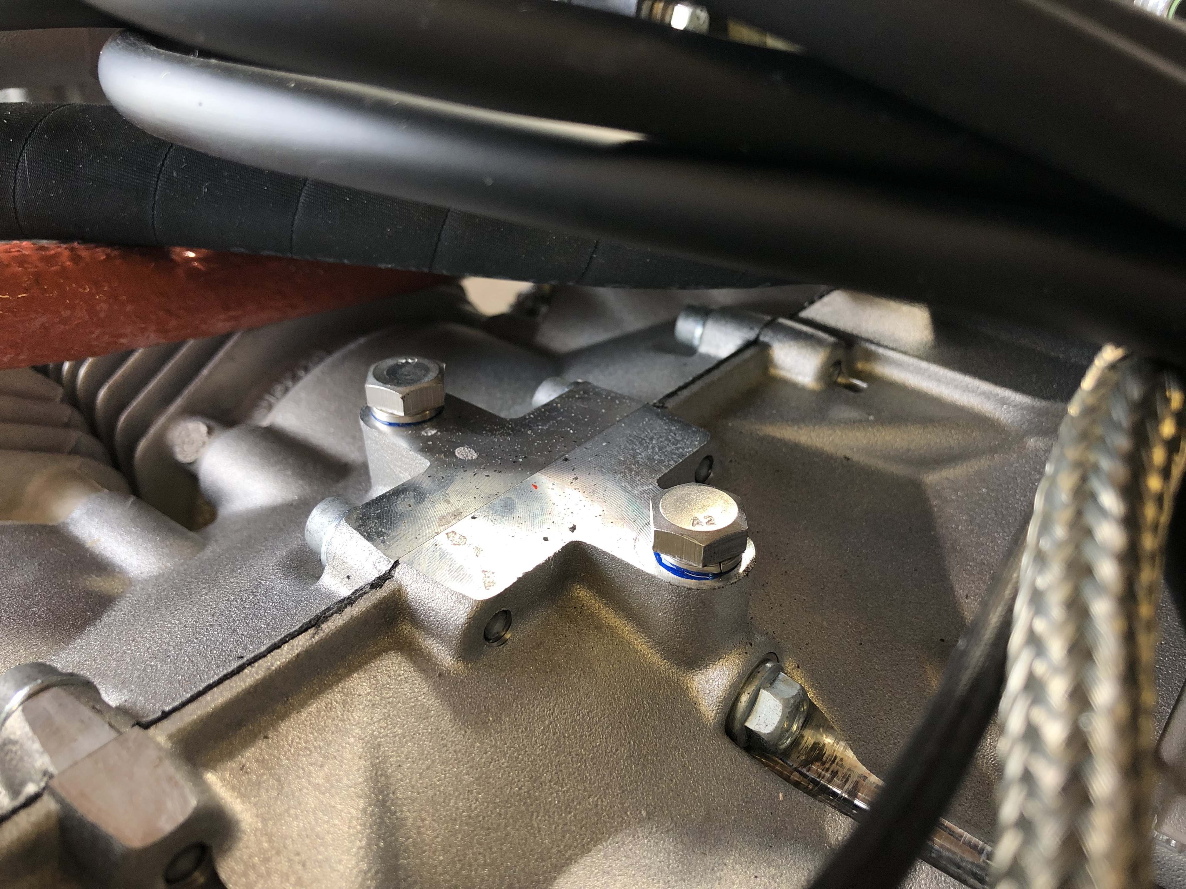
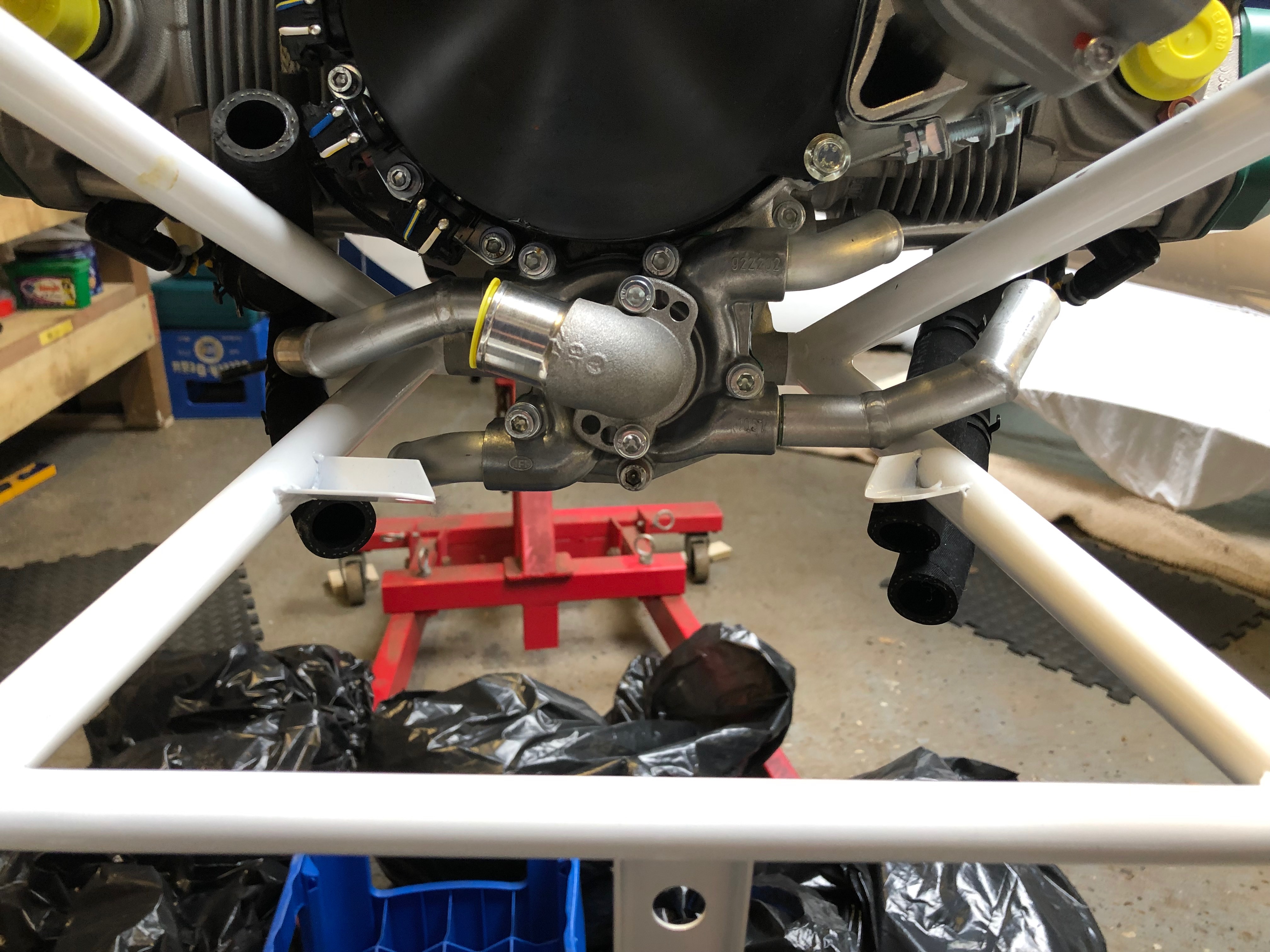
The water pump refitted clearly showing the new position of the modified pipes around the Bristell engine mount. The rubber pipes will be refitted tomorrow allowing the Loctite to further harden.
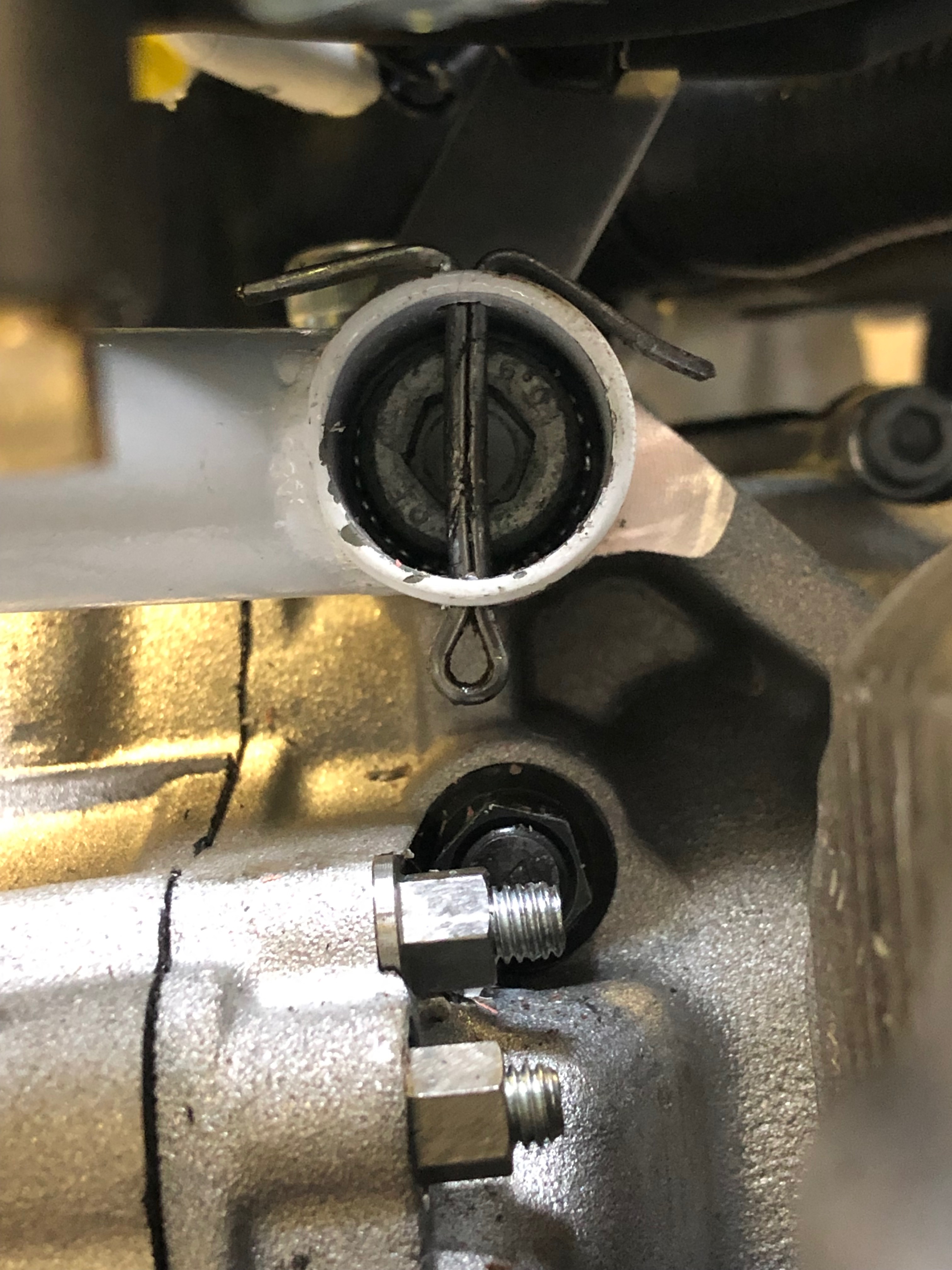
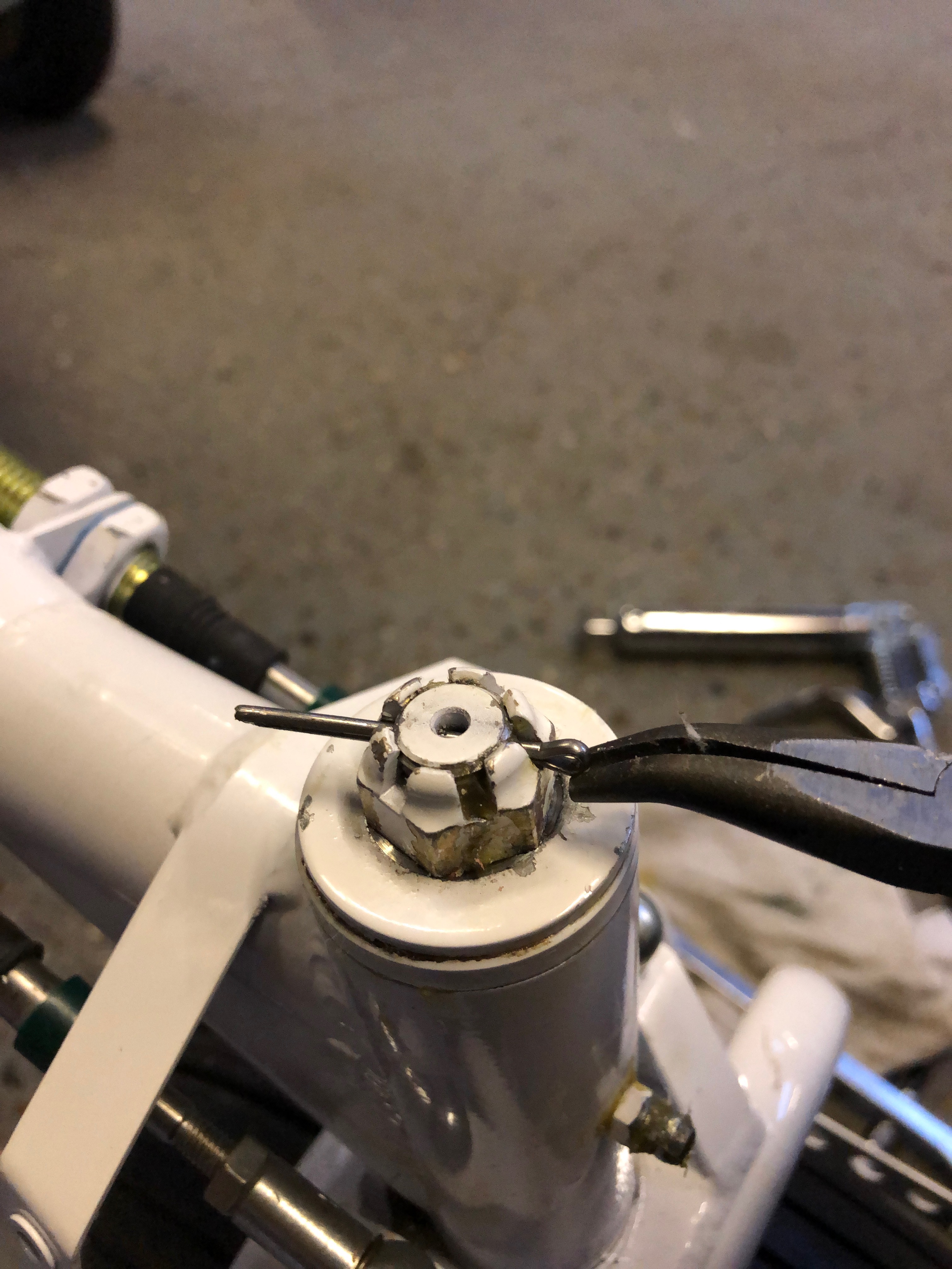
Split pins are inserted through the engine mount to retain the engine bolts should they loosen ensuring that they won’t fall out when in service.
Three of the split pins are easy to install but top right is impossible without taking the control unit off so this one was installed upside down but still does the job of retaining the bolt should it work loose.
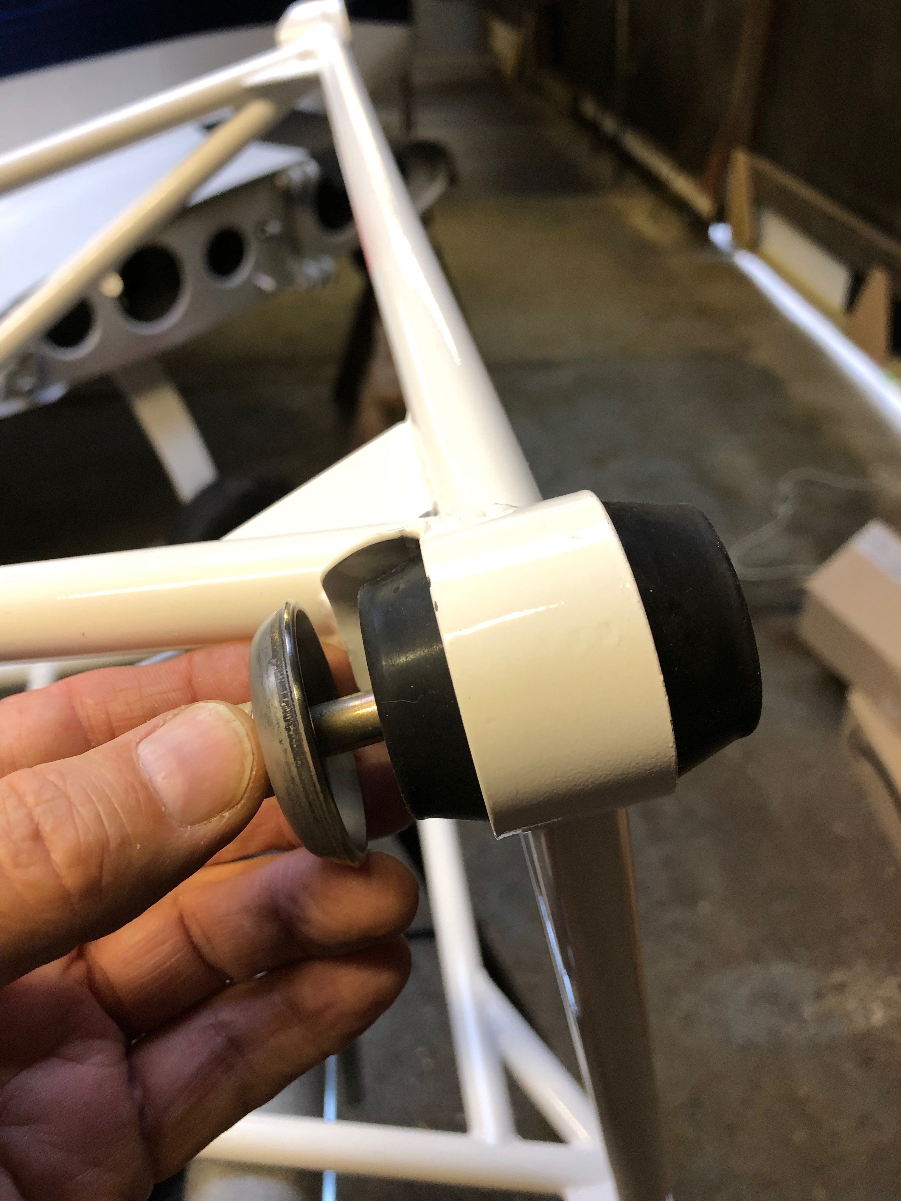
I test fitted the engine vibration bushes onto the engine mount in preparation for hanging the engine tomorrow.
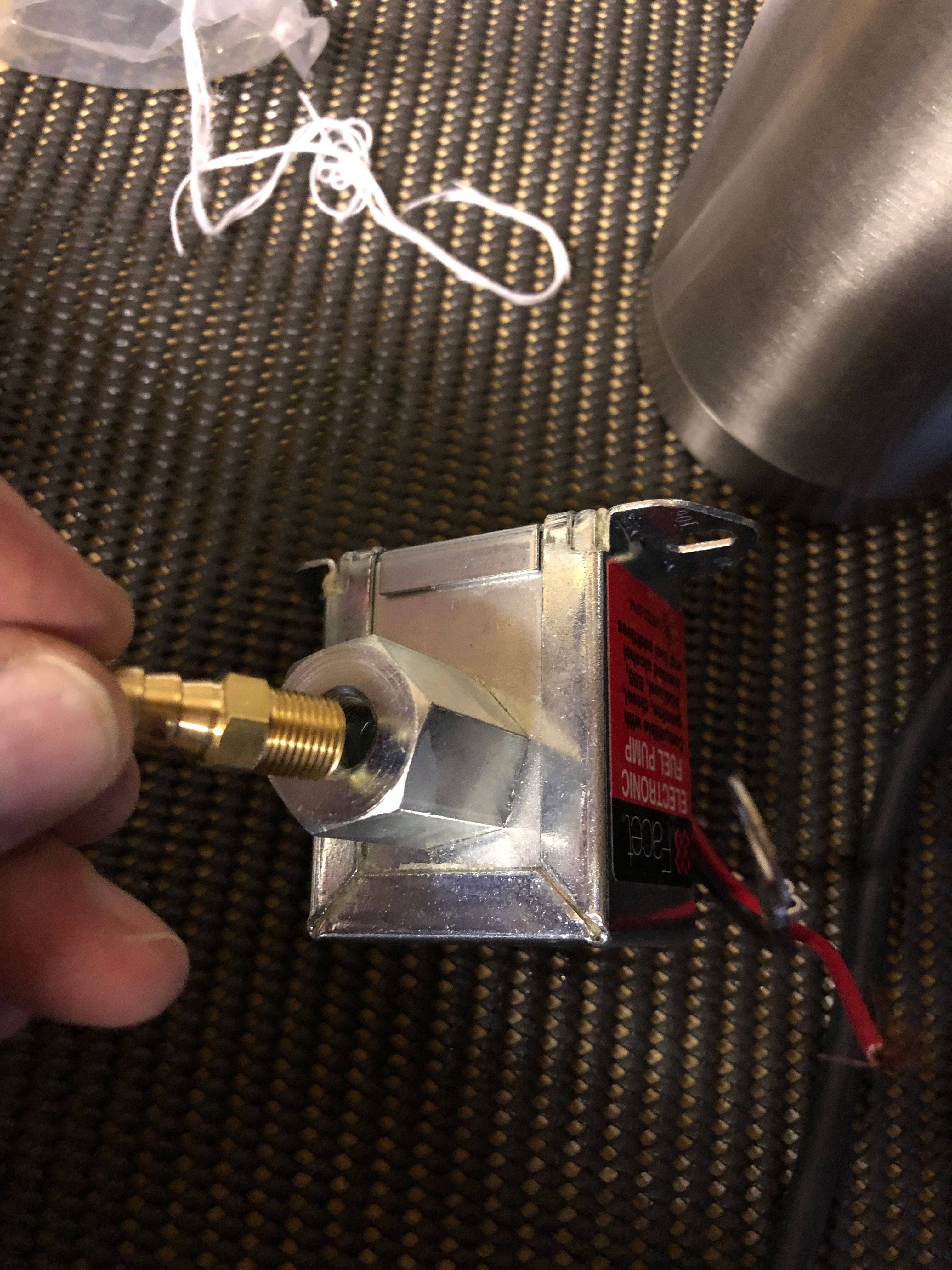
One of the miscellaneous tasks that needs to be done. The electric fuel pump fittings are screwed in after applying Wellseal around the thread ensuring the ‘water tight’ seal.
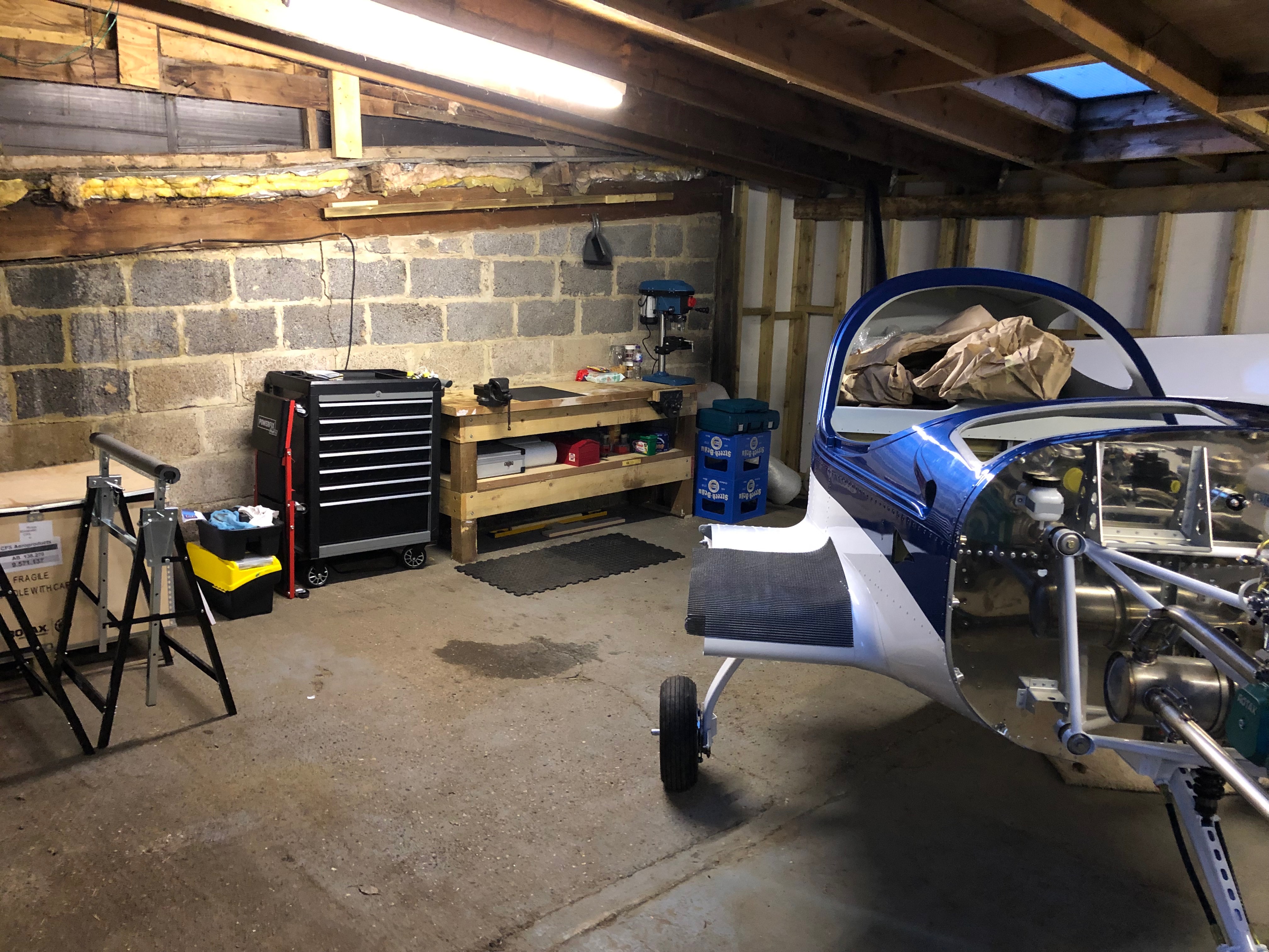
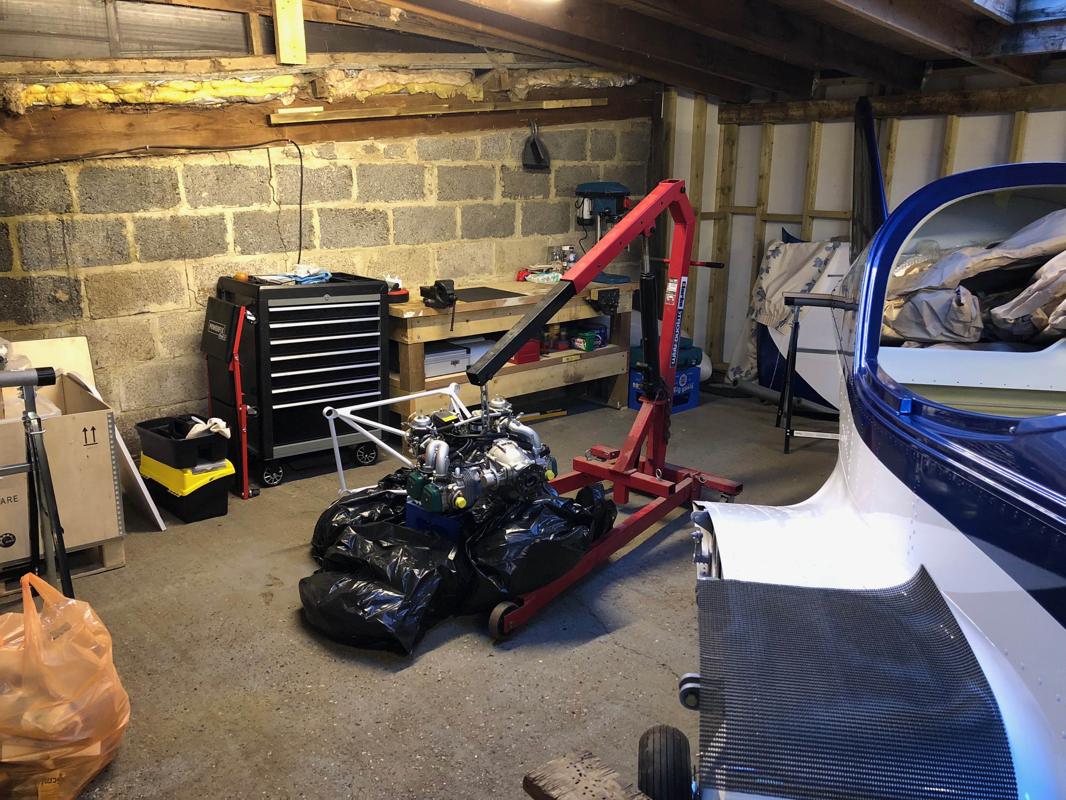
The usual resting place overnight. Hopefully the last time I’ll have to do this!
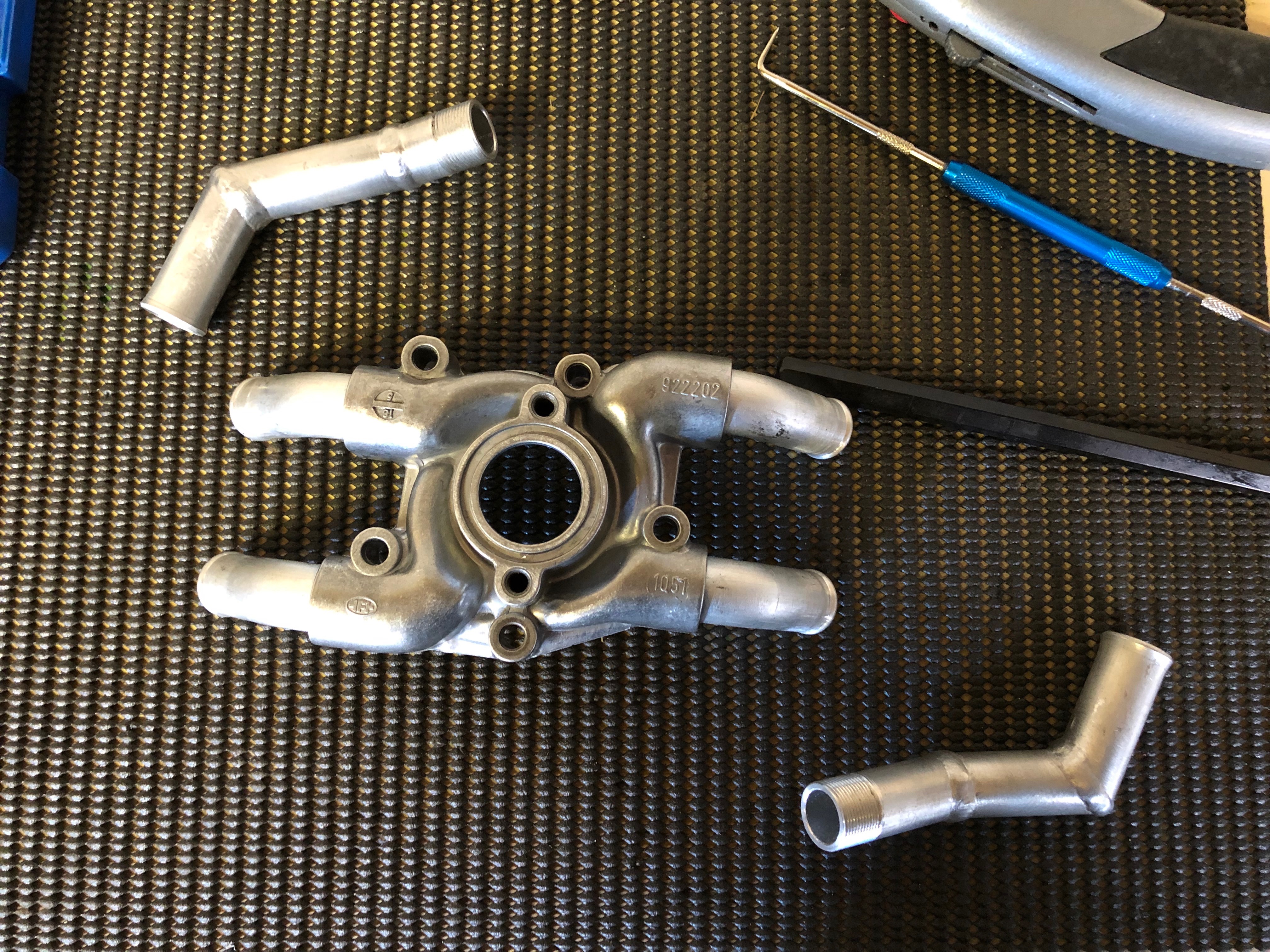
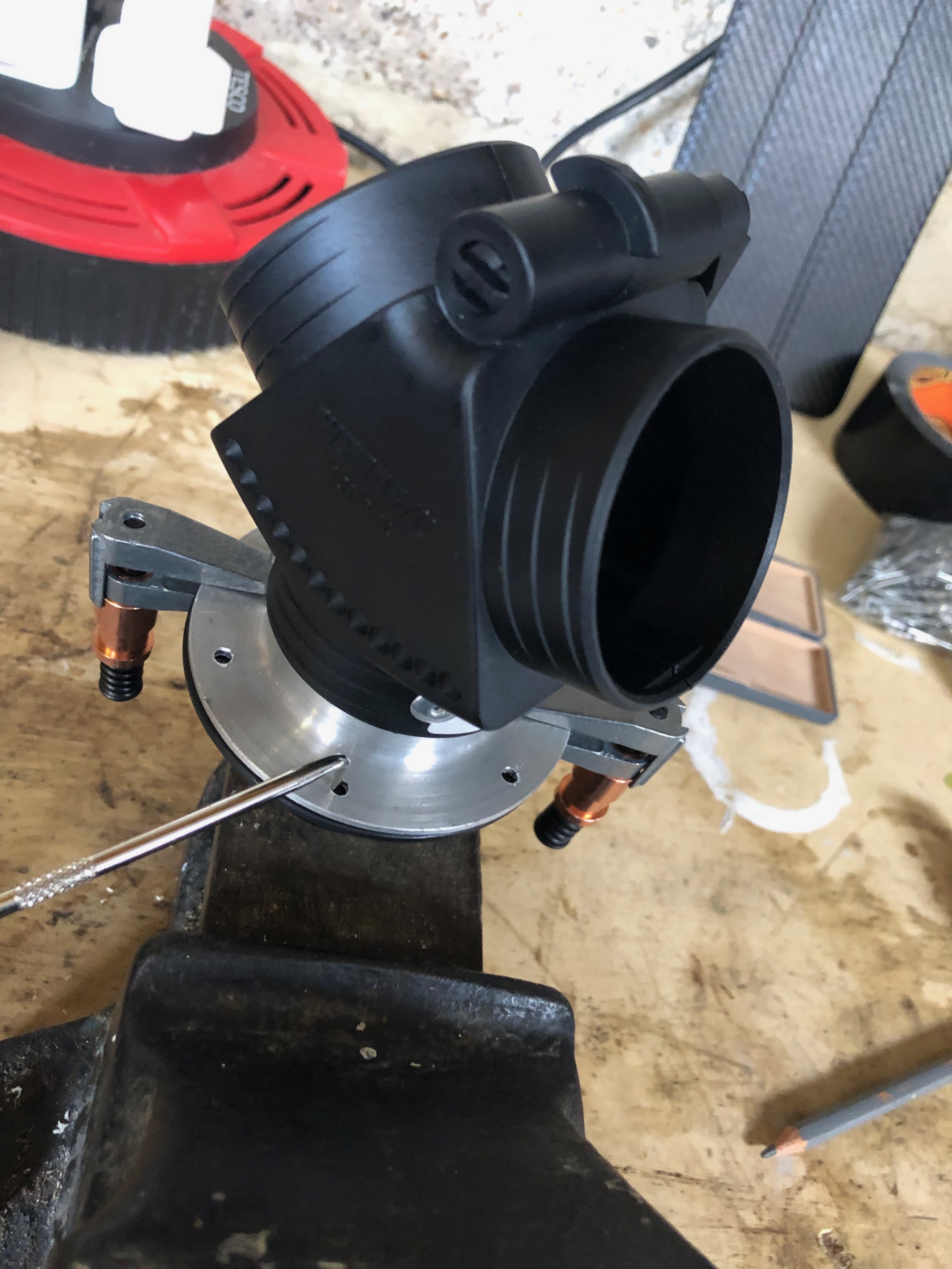
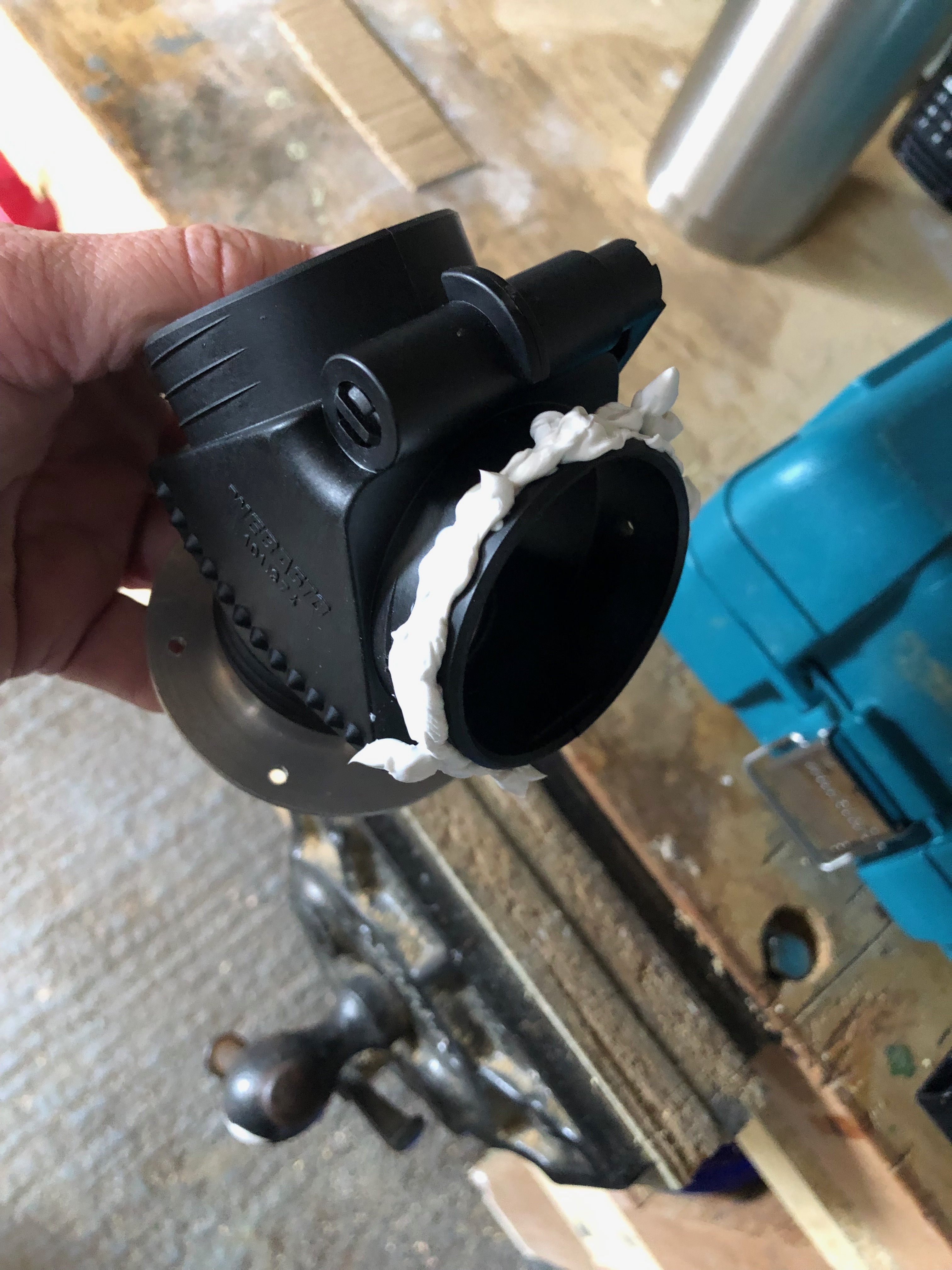
Time to modify the pump. The top left and bottom right pipes will be changed and the other two will be removed and refitted at a different angle to suit the Bristell engine mount.
The pump and pipes are heated until the existing Loctite bubbles and then a long bar is used to unscrew the pipe. This is repeated for all four pipes.
The old Loctite is removed by using a scribe and some thinners ready for reuse.
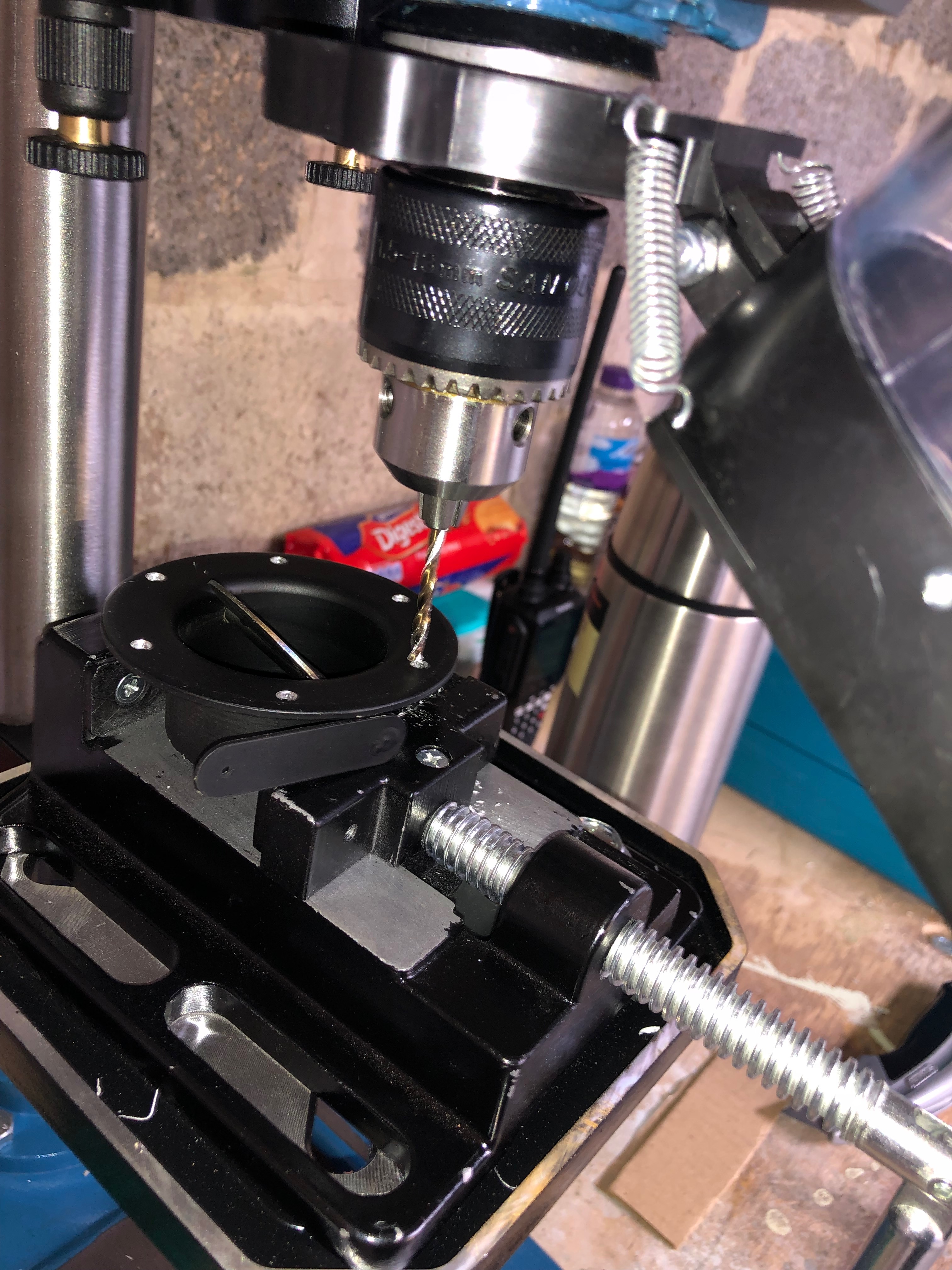
As the new pipes are manufactured by cutting and welding the insides should be checked for weld debris and cleaned.
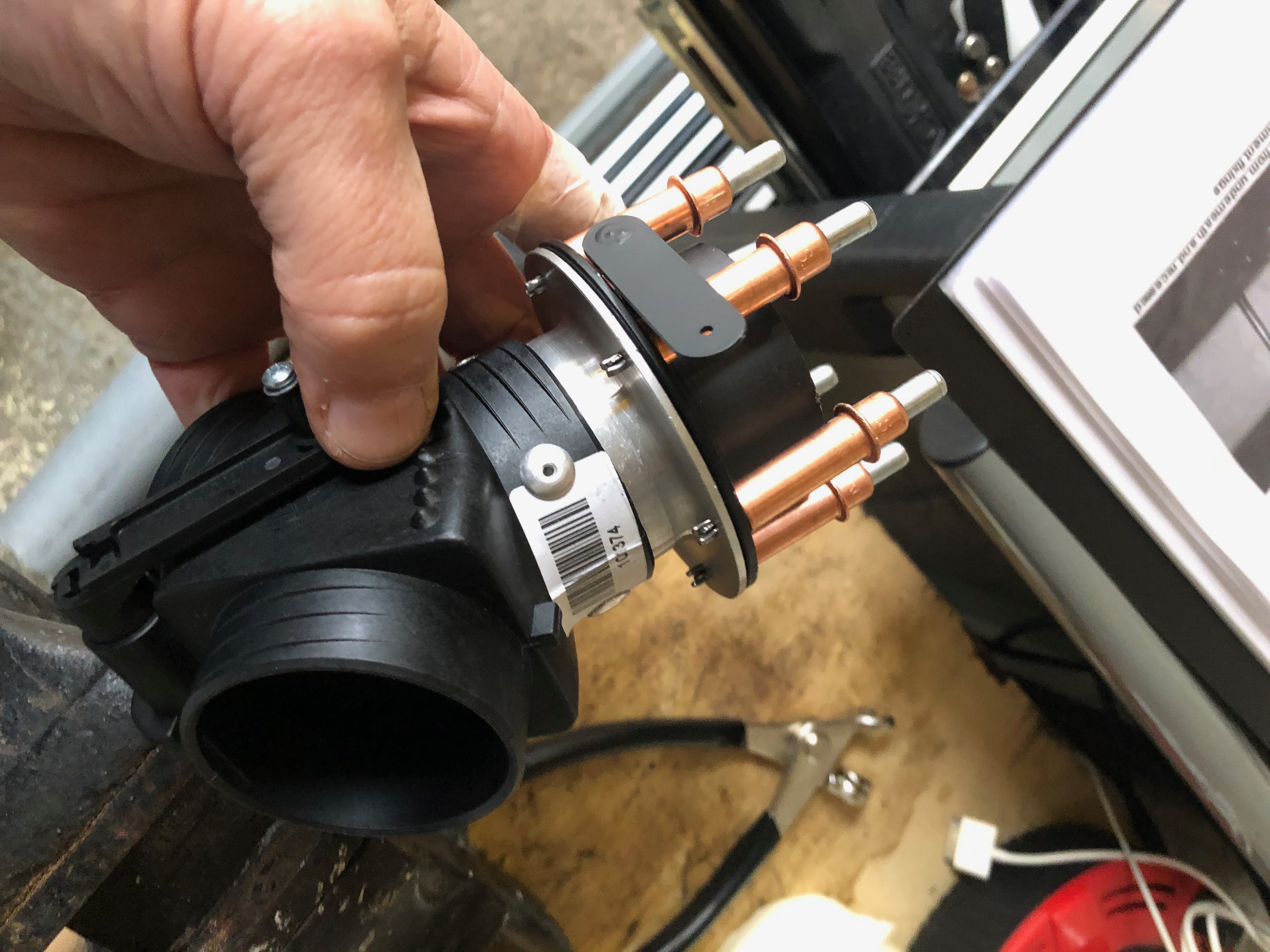
Loctite 620 is applied to the thread and the first of four pipes are refitted. The pump is offered up to the engine and the angle of the pipe is checked to ensure that it doesn’t foul the engine mount and that there is enough clearance to refit the water pump pipe .
All the pipes fitted and angled correctly and left to set overnight.
Again the engine is lowered overnight for peace of mind.
Time to lift the engine. Luckily there is an engine hoist onsite that belongs to Richard and he didn’t mind me using it.
Quite nervous about lifting the engine and and trusting the hoist and the lifting bracket that I made but it seems to be holding up ok.
As the Bristell uses its own engine mount two of the pump aluminimum pipes need to be repositioned and the other two need to be replaced with modified pipes that come with the kit.
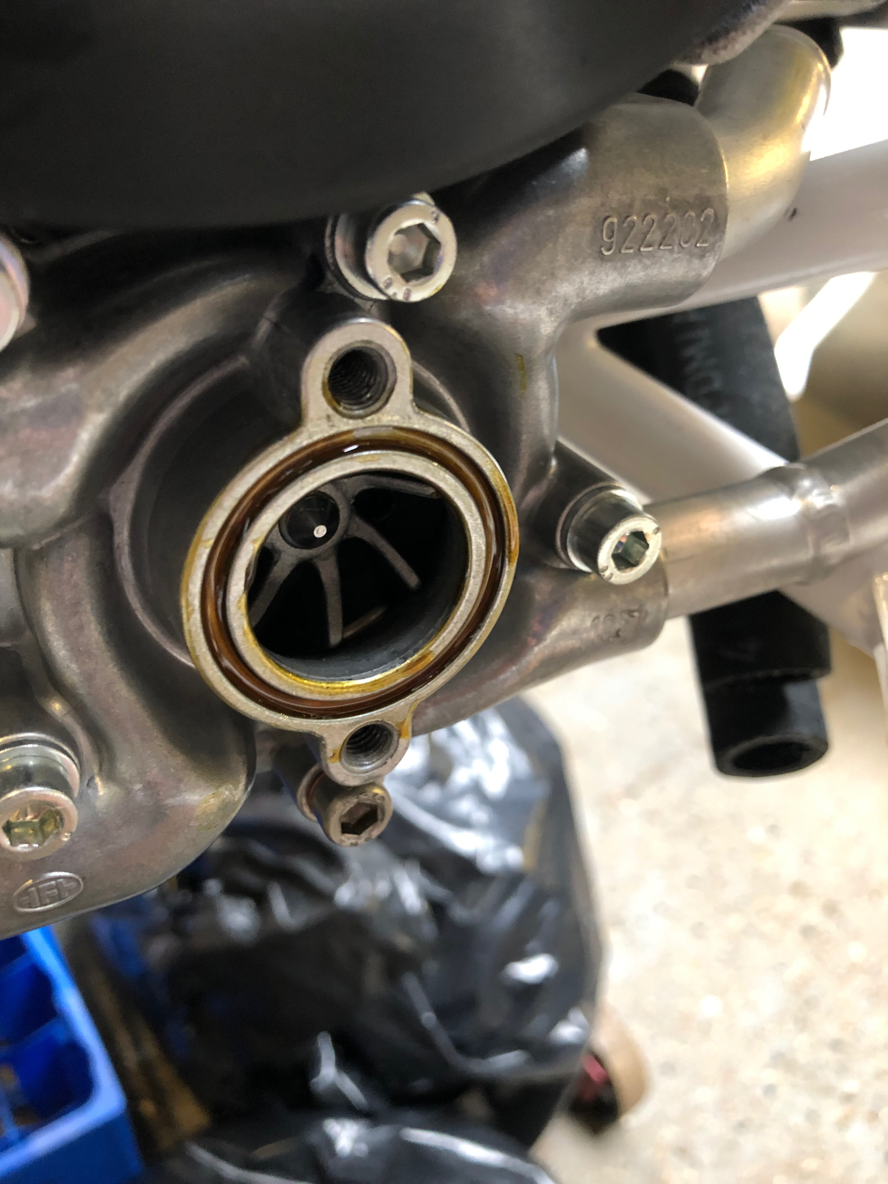
So the pump needs to be removed.
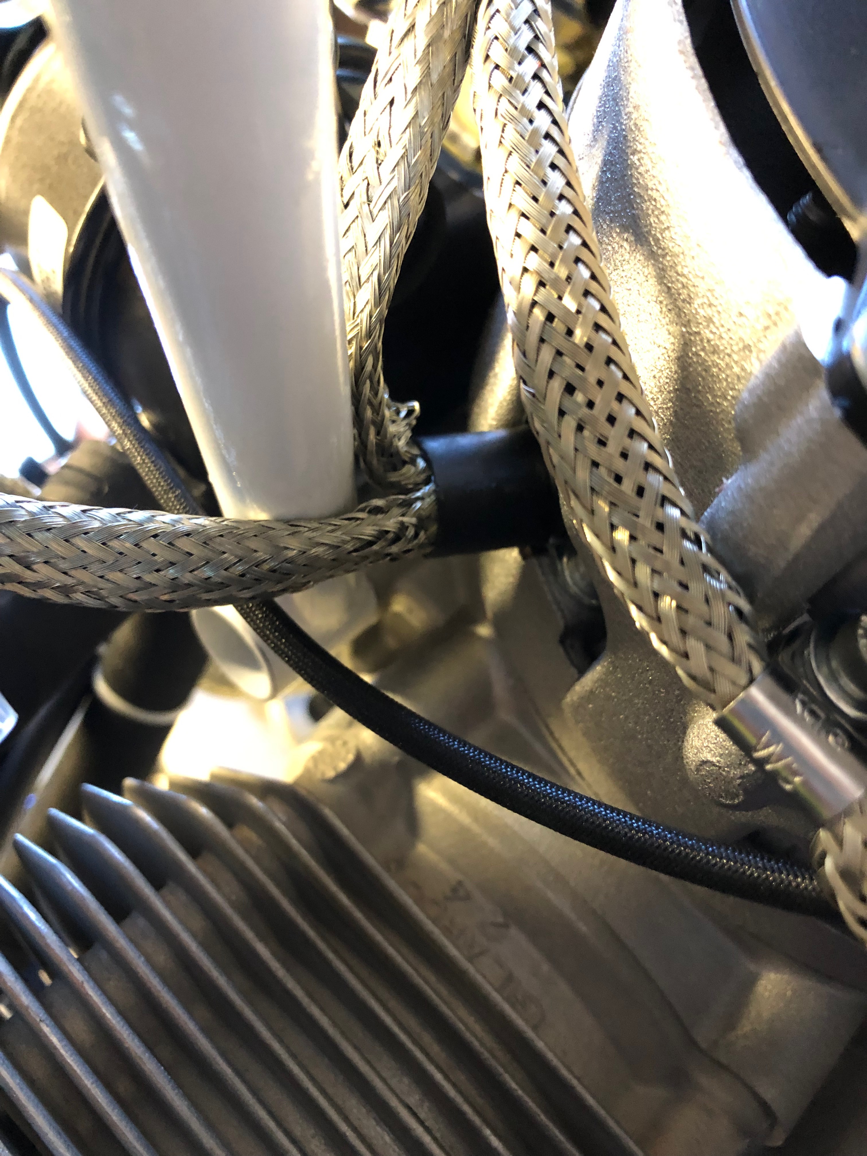
The engine mount needs to be fitted as it’s the only way that you can position the new water pump pipes. The mount is quite tight to fit and you need to make sure that you don’t catch any cables. The top right bolt needs to be removed as that becomes one of the engine mounting bolts that are fitted later.
As stated above, it’s a very tight fit so care must be taken to ensure that cables don’t get damaged. They will need to be protected before the engine goes into service.
The engine mount fitted. The water pump pipes need to be removed but I decided to think it through a bit more before carrying out the work tomorrow.
Now I have my grease gun I can fill the steering bearing with universal grease.
and then refit the castellated nut and fit a new split pin.
The other bearing that needs to be filled with grease is the nosebag pivot. It’s tricky to get to and once filled it’s tricky to remove the fitting from the grease nipple.
For peace of mind I’ve lowered the engine onto a beer crate and surrounded it with the packing that came with the engine so I can leave it overnight.
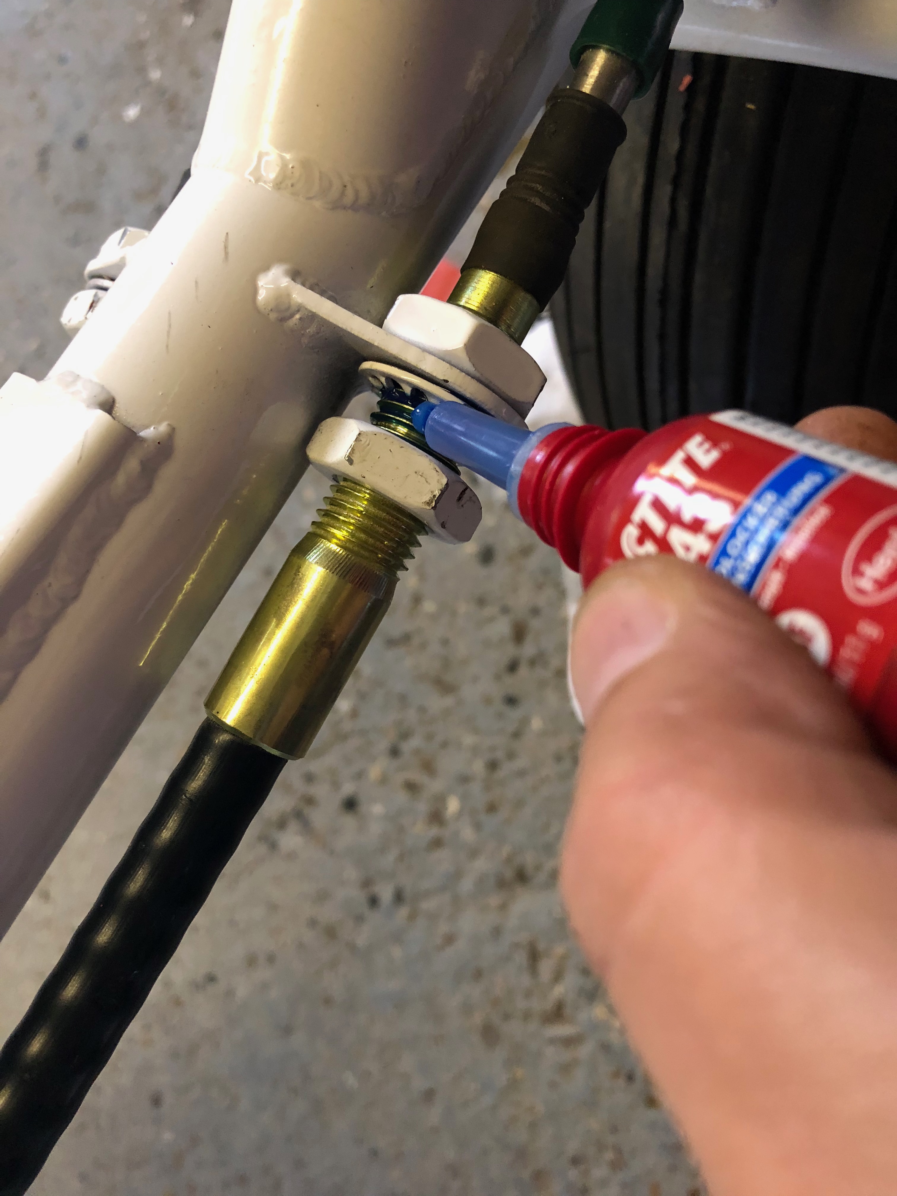
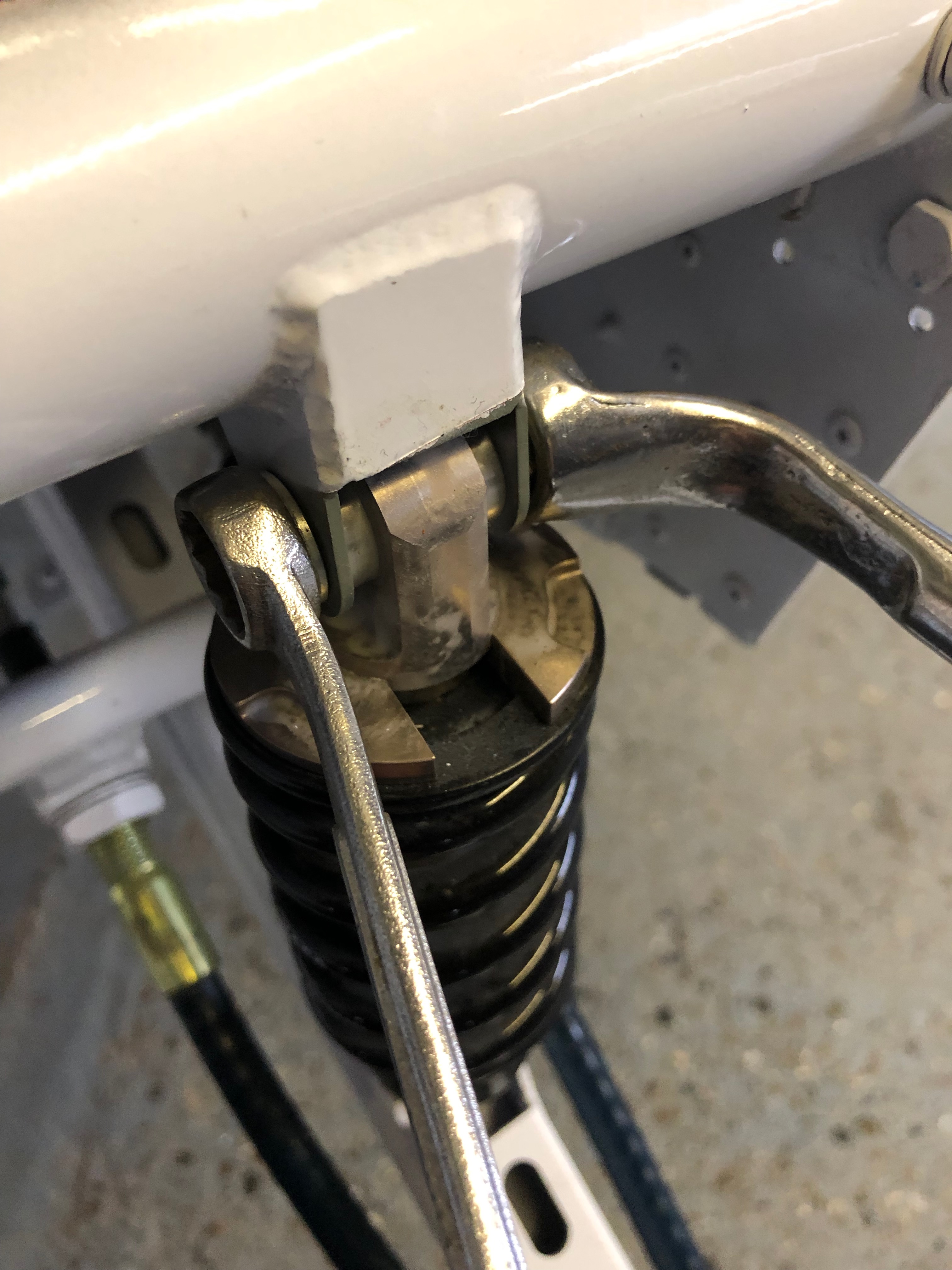
Although the Teleflex cables are already installed the nuts need to have Loctite 243 applied and retightened to ensure they don’t loosen during service.
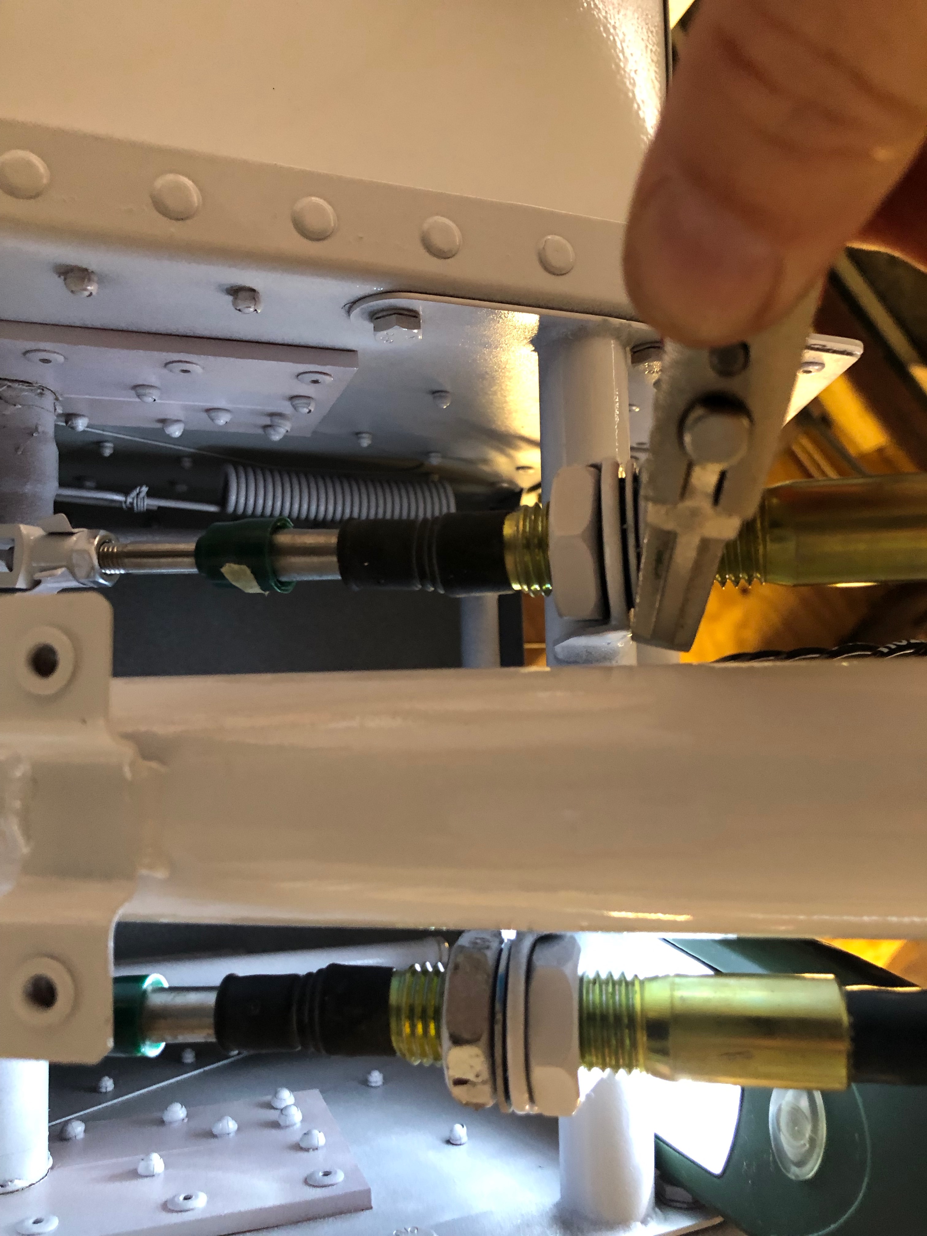
Not forgetting those underneath…
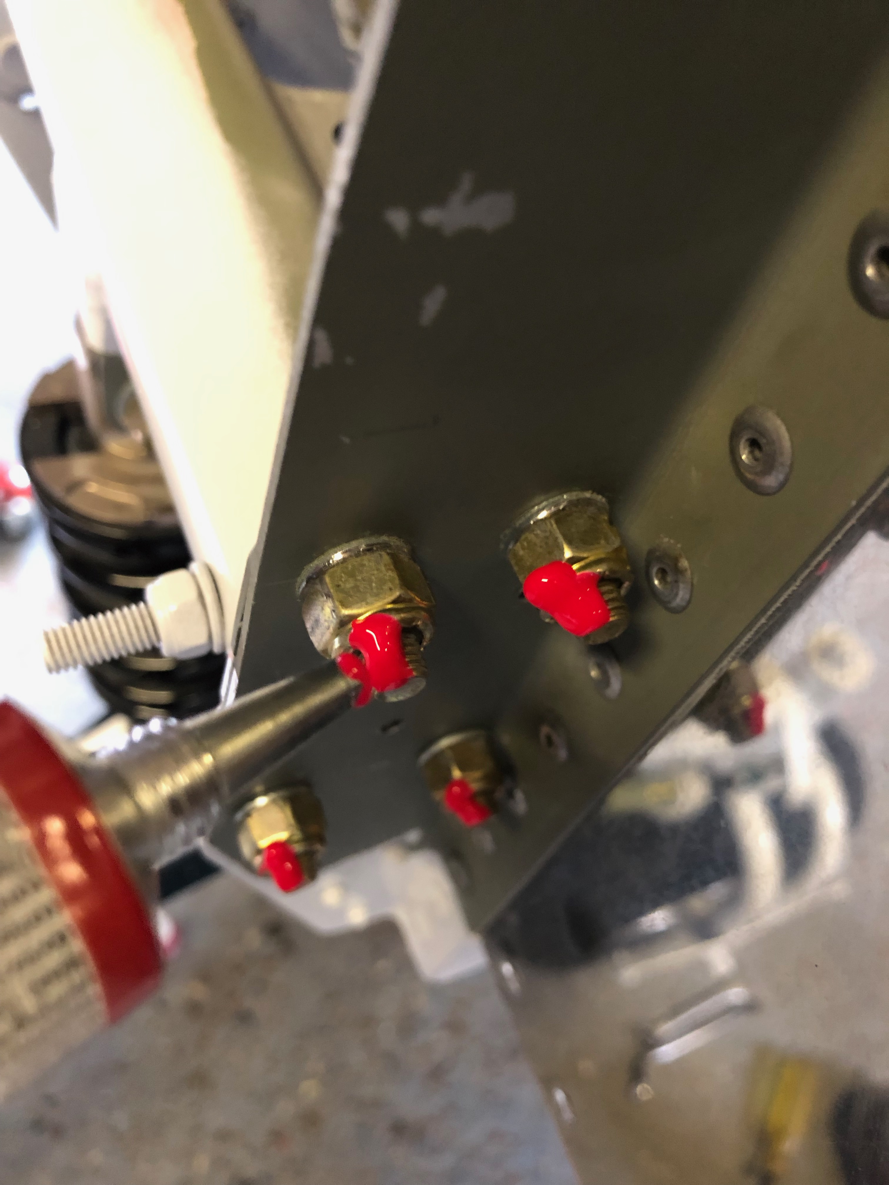
All the nuts and bolts also need to be checked.
Once checked then Torque Seal is applied so an easy visual check can be made to ensure that they haven’t loosened.
I wasn’t happy with the screws used for mounting the control unit so I removed the Rivnuts and used M6 stainless steel nuts and bolts instead.
A view of the Firewall with the Torque Seal clearly visible.
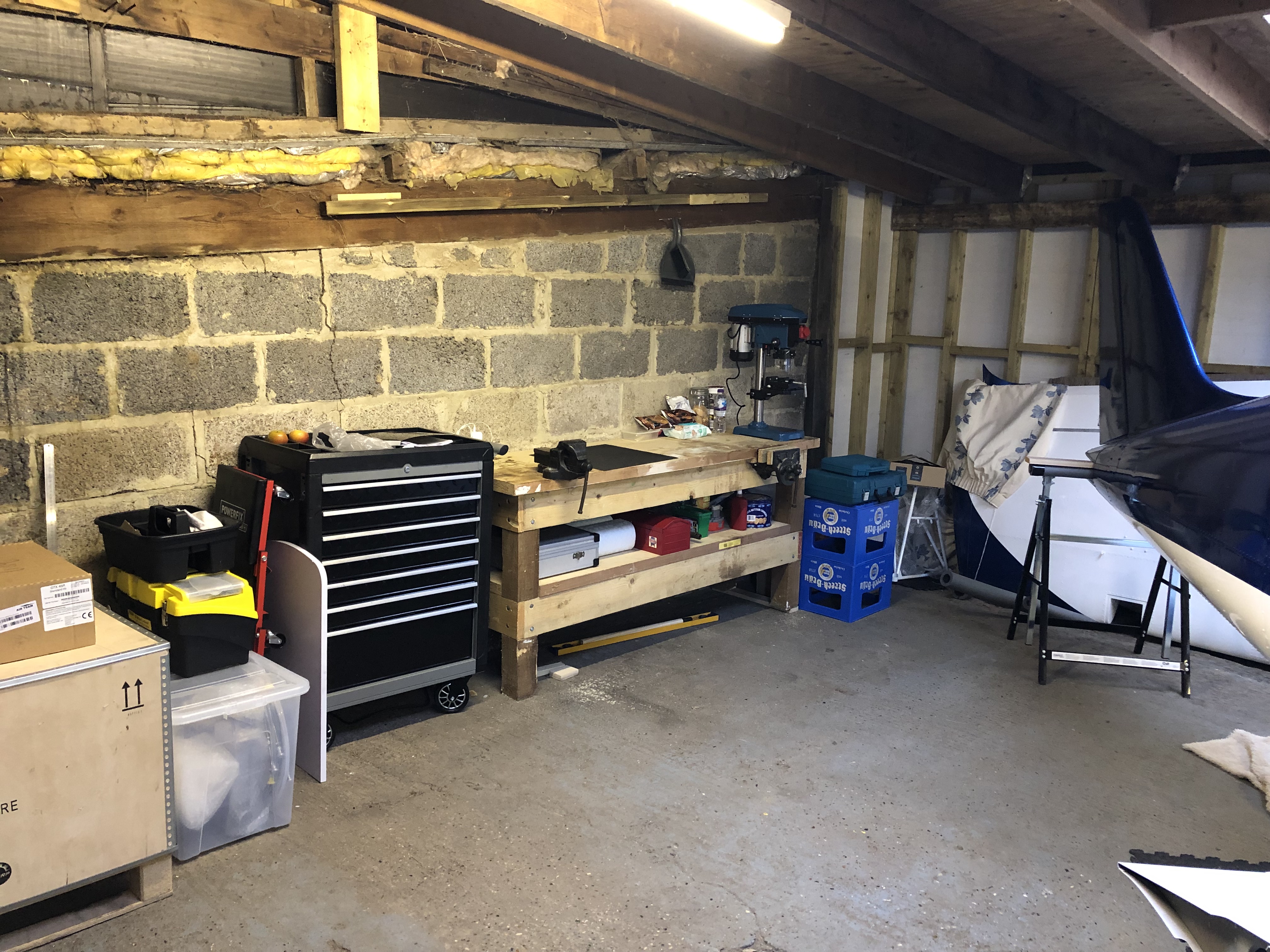
A tidy of the workshop was required to give me a bit more space on the workbench and clear area to work in.
Time to install the flap motor. The bushes need to be sprayed with Lithium grease and then installed.
Fairly easy install but just a bit fiddly to install. You must connect the flap motor arm to the flap actuating arm first as you can’t get the bolt in after.
Motor installed.
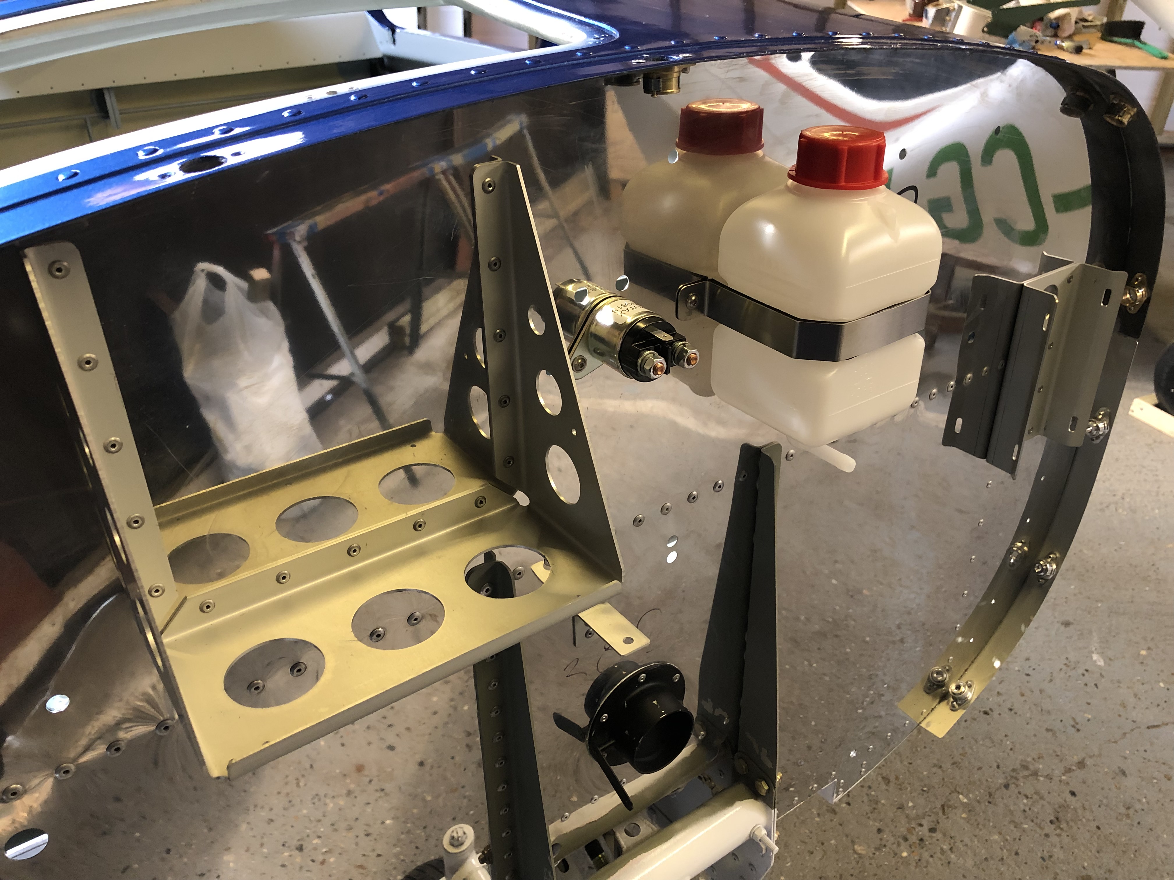
Next to be installed is the starter solenoid. A couple of M4 Rivnuts are installed with hex top screws to fix.
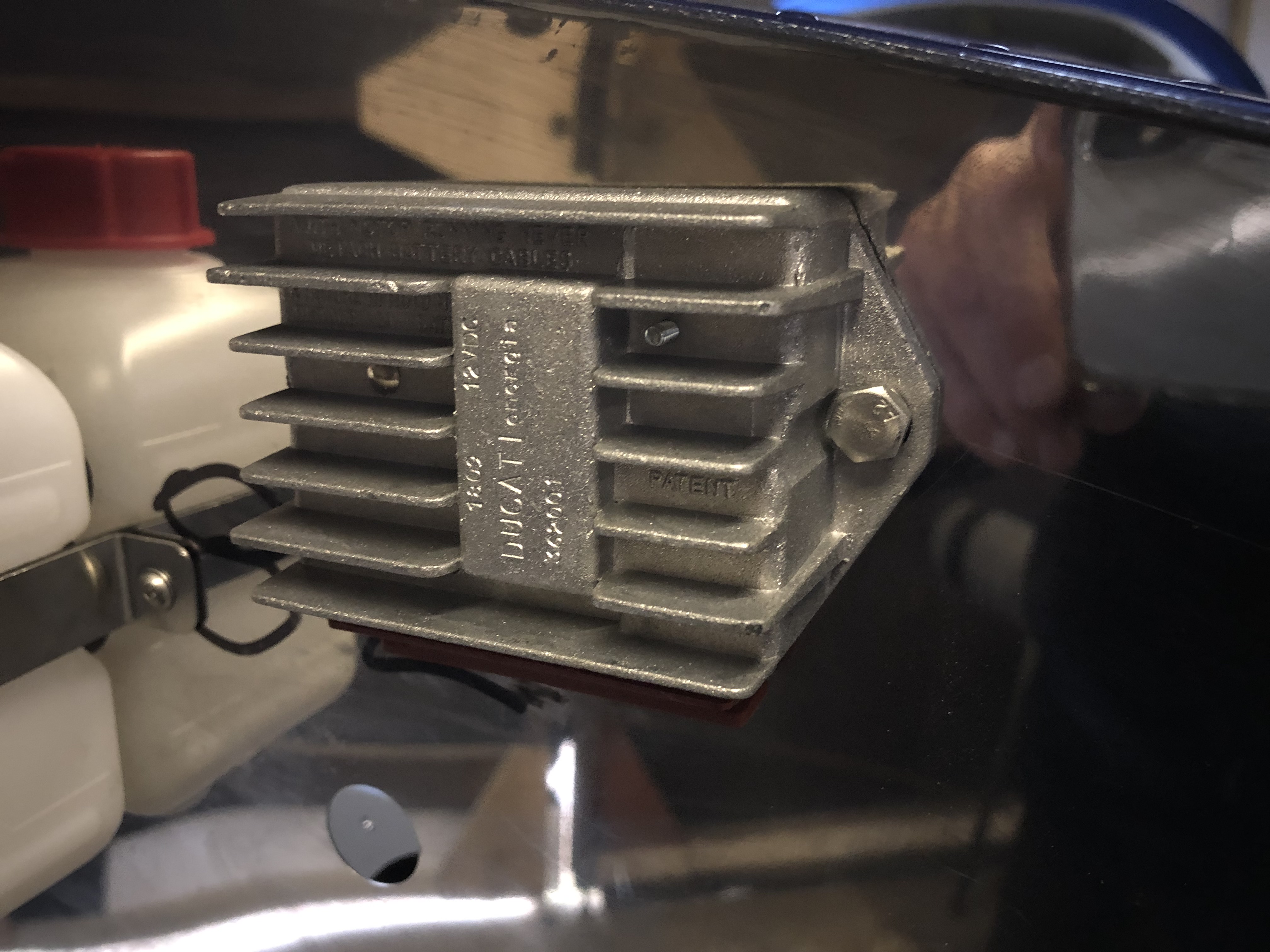
Now the Rotax control unit is installed using Rivnuts and screws.
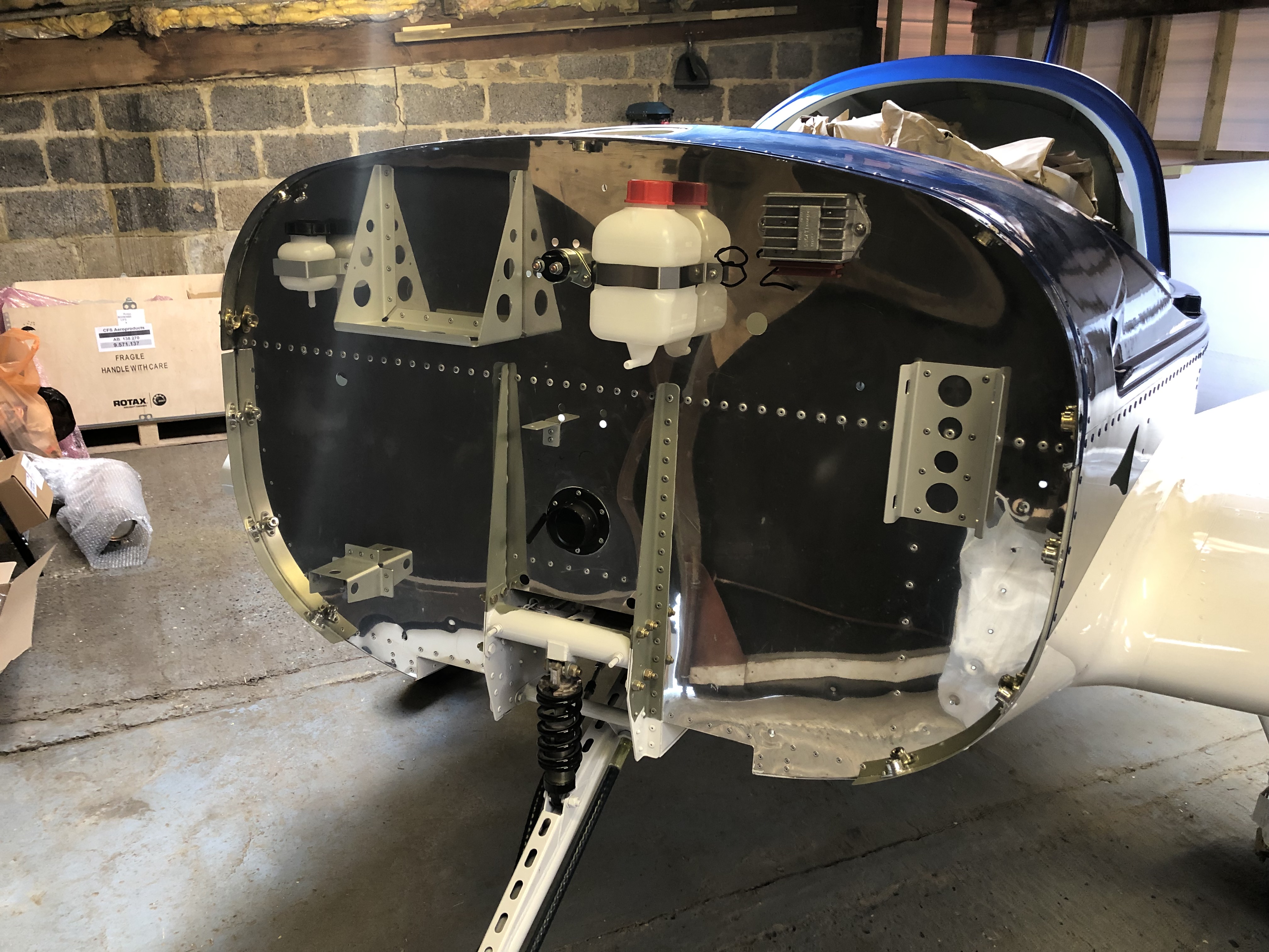
The Firewall at the end of the day.
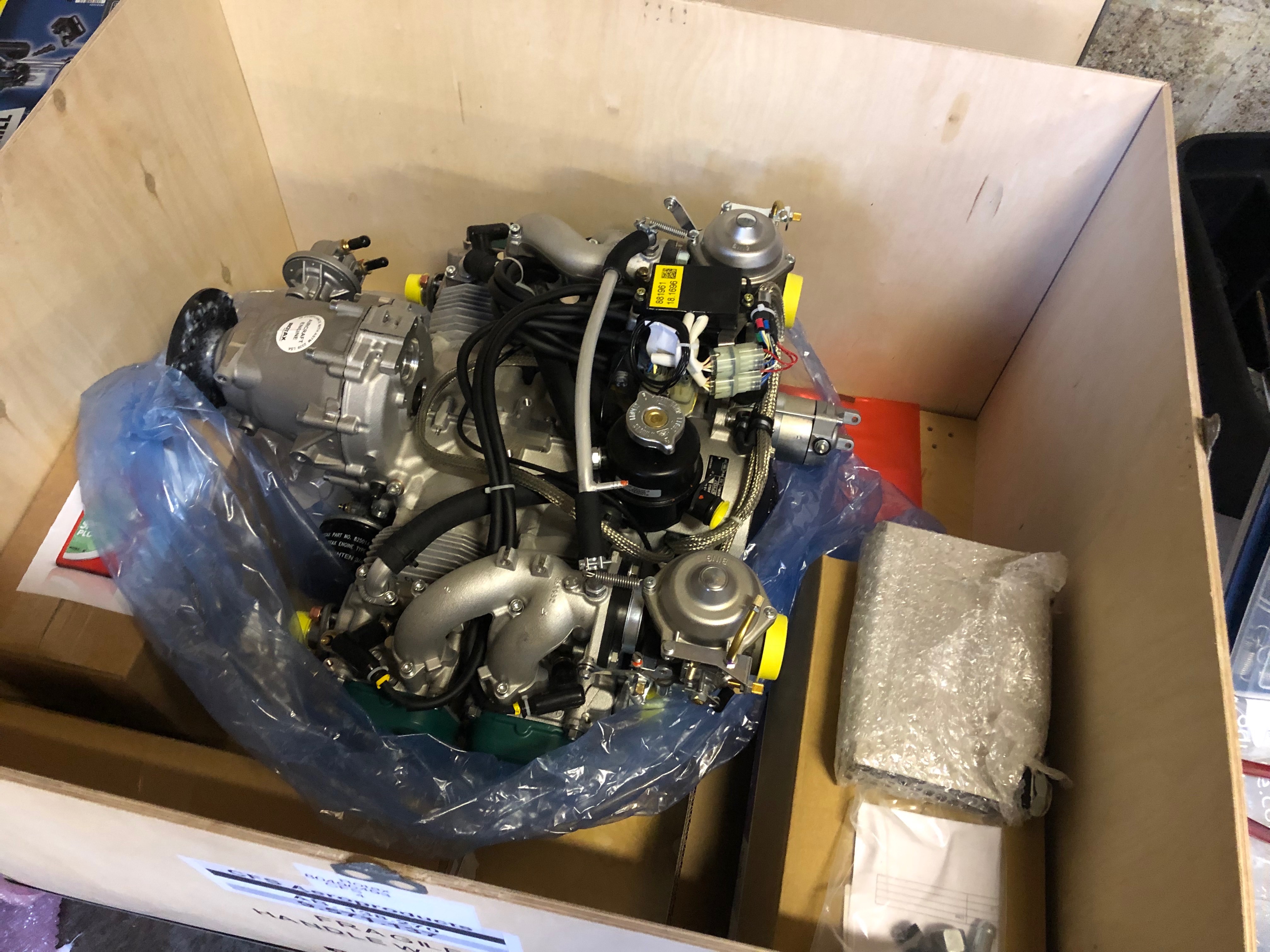
The engine needs to be lifted out of the crate and suspended whist the water pump is modified and engine mount is attached.
A bracket needed to be made from steel bar so it can be used for lifting.