Thursday 4th July 2019

Music: Reverend And The Makers

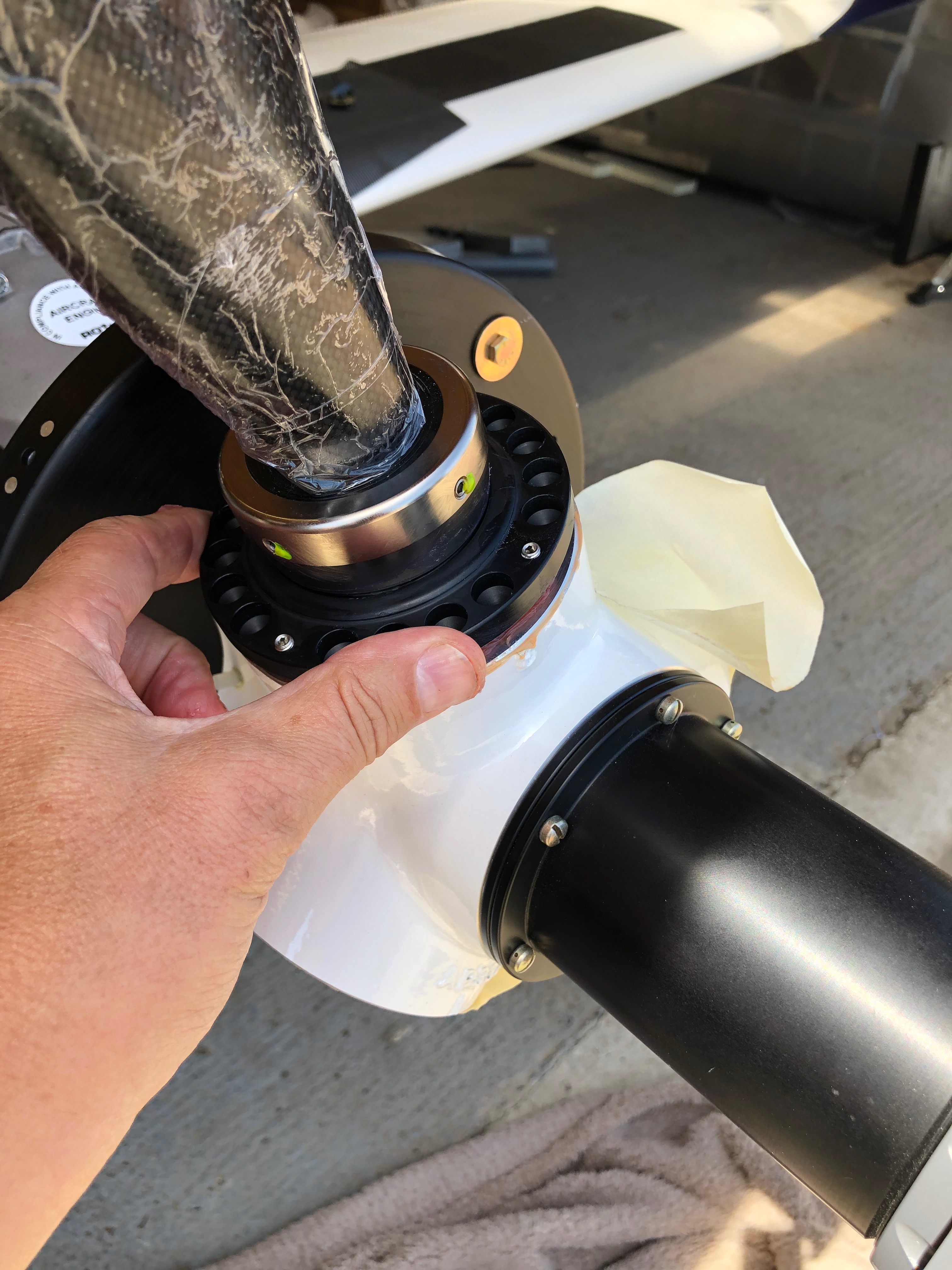
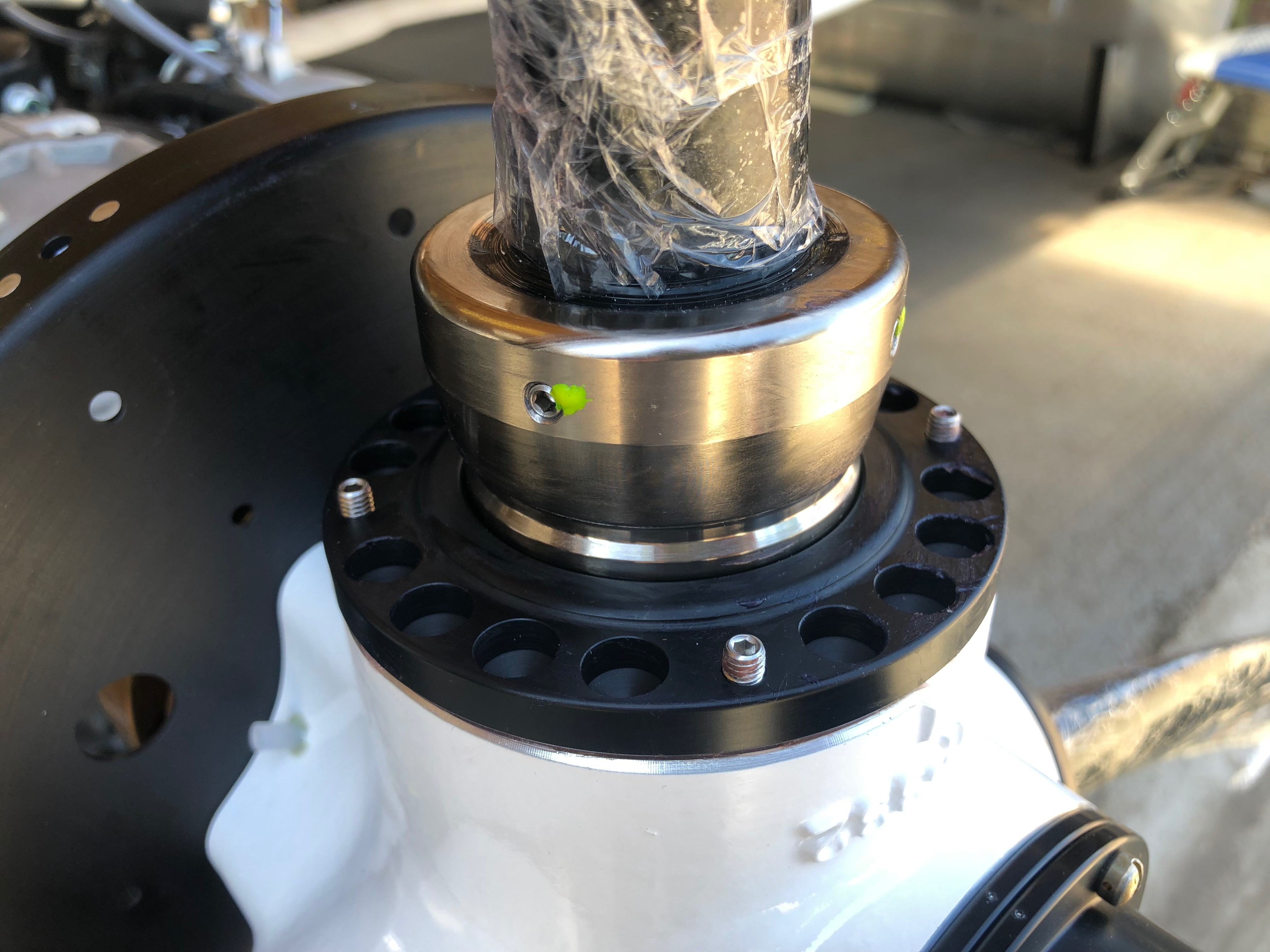
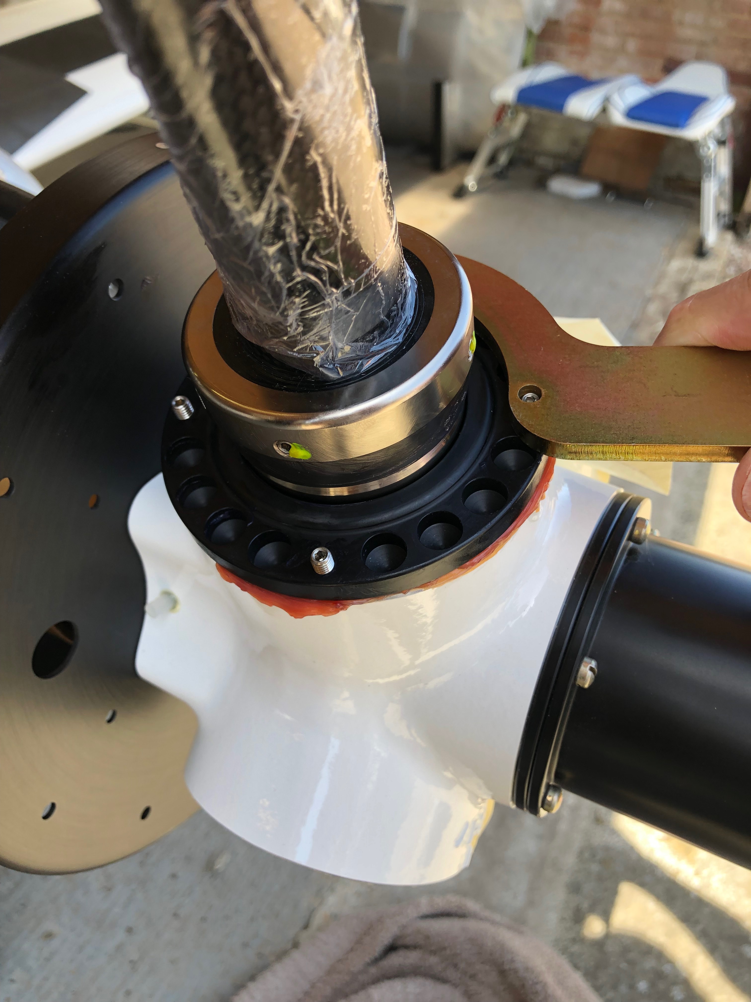
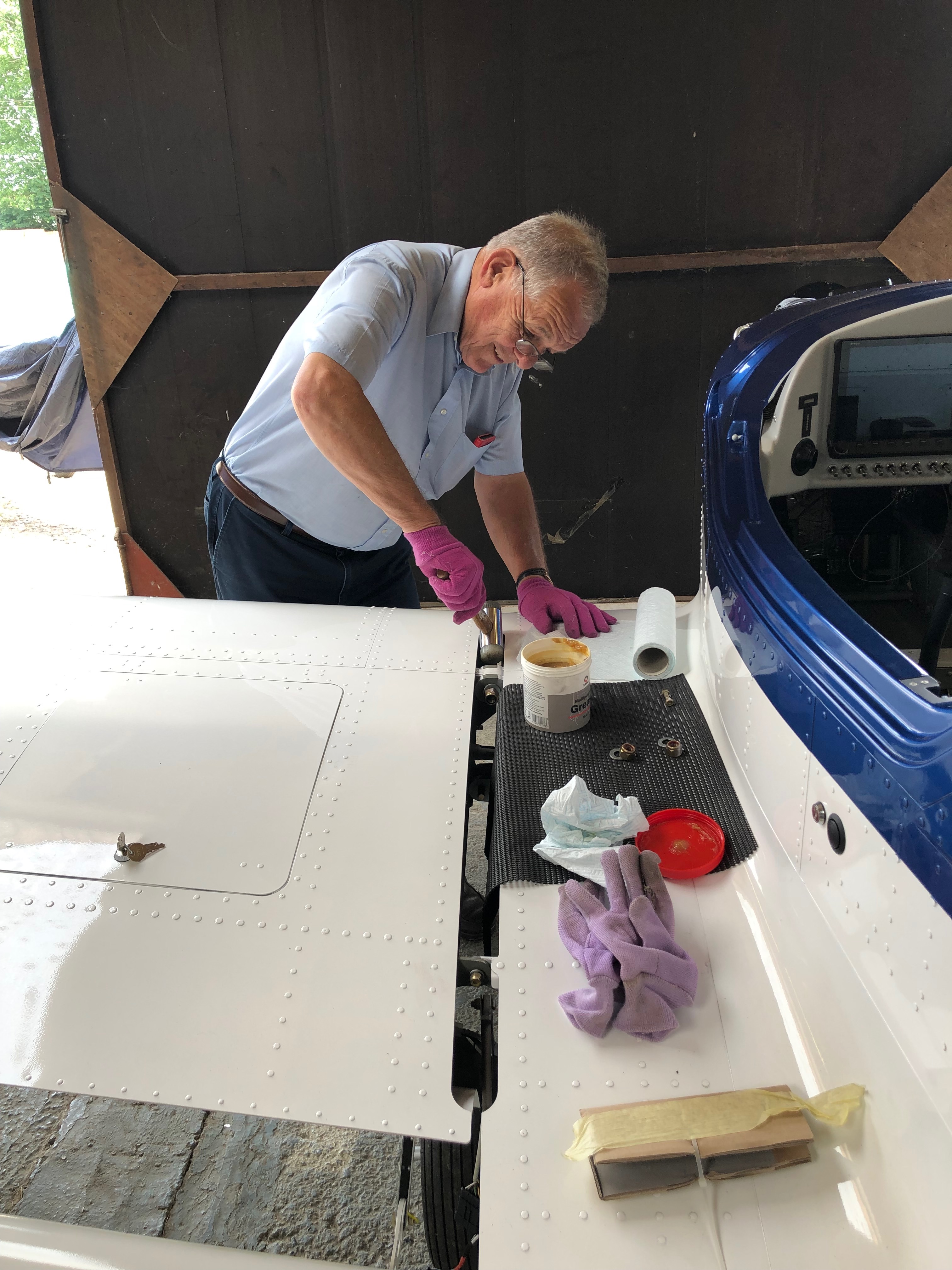
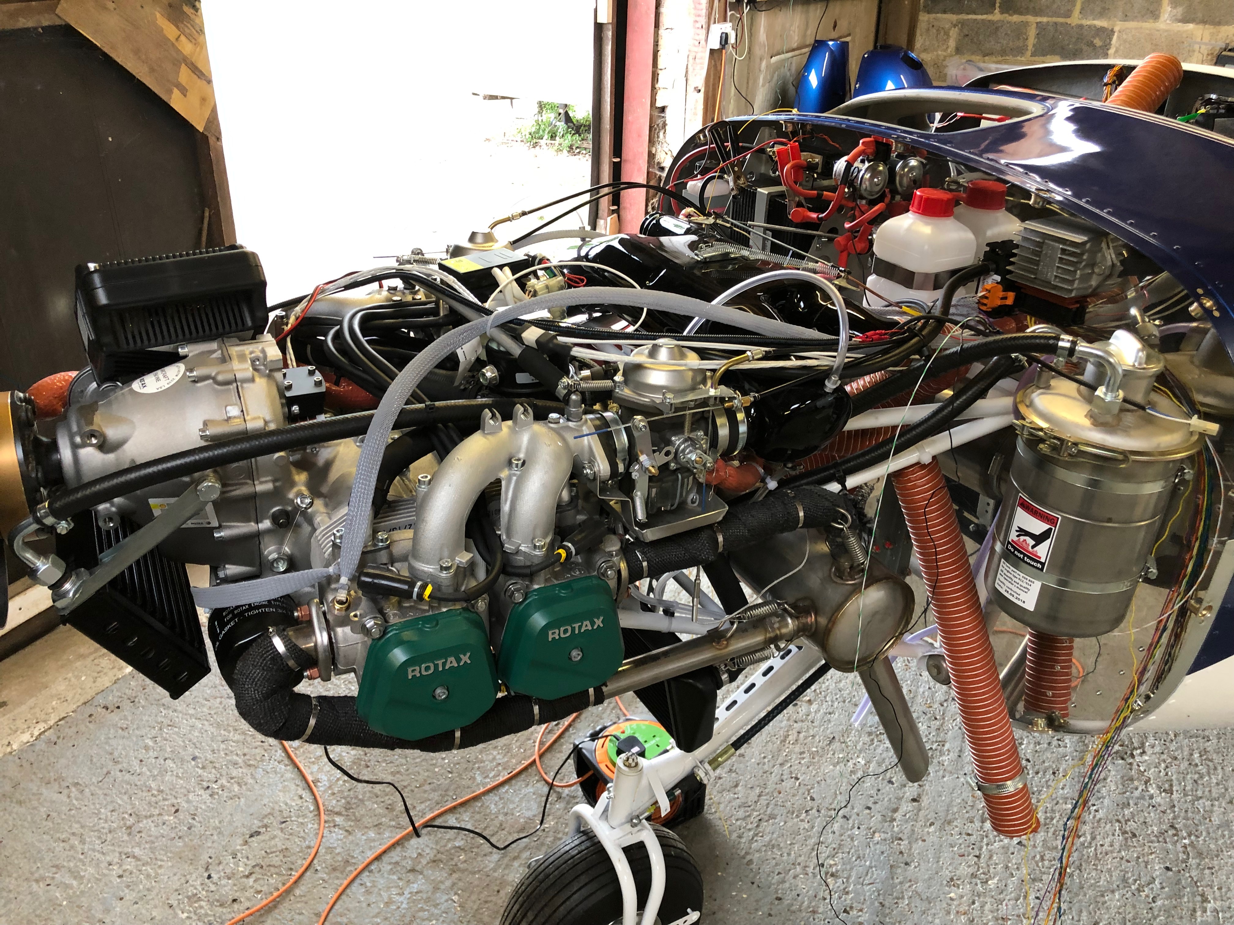
The main job today is to fit the propellor blades. Luckily the Aeroshell Grease that was supposed to have been delivered next Monday was delivered a couple of days ago so I can get on with it. Once fitted I can purge the oil system and add the antifreeze.

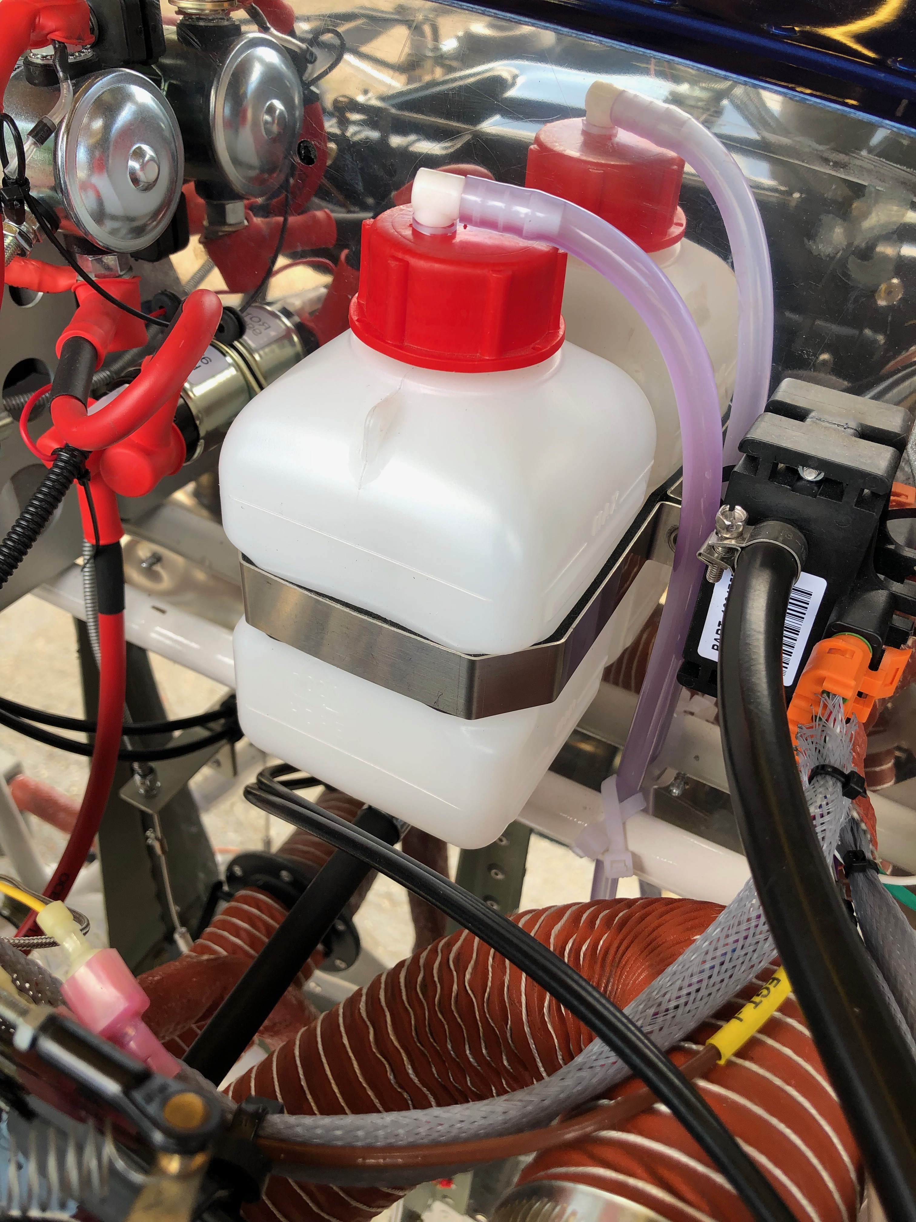
I had a call with CFS Aero who have now acknowledged that it would be a good idea to change the floats before I first fly the aircraft as Rotax have had a problem with sinking floats that leads to flooding of the engine and the possibility of engine failure. They will be sent in the post in the next couple of days. They have also confirmed that Halford OAT antifreeze is ok to fill the coolant system.

Once the protective seal has been removed it reveals the pitch change mechanism. It’s been greased after manufacture but needs a further coating as per a service bulletin.
I think I may have ordered the wrong size tin of grease 🙂 It was at a bargain price which was cheaper than smaller tins.
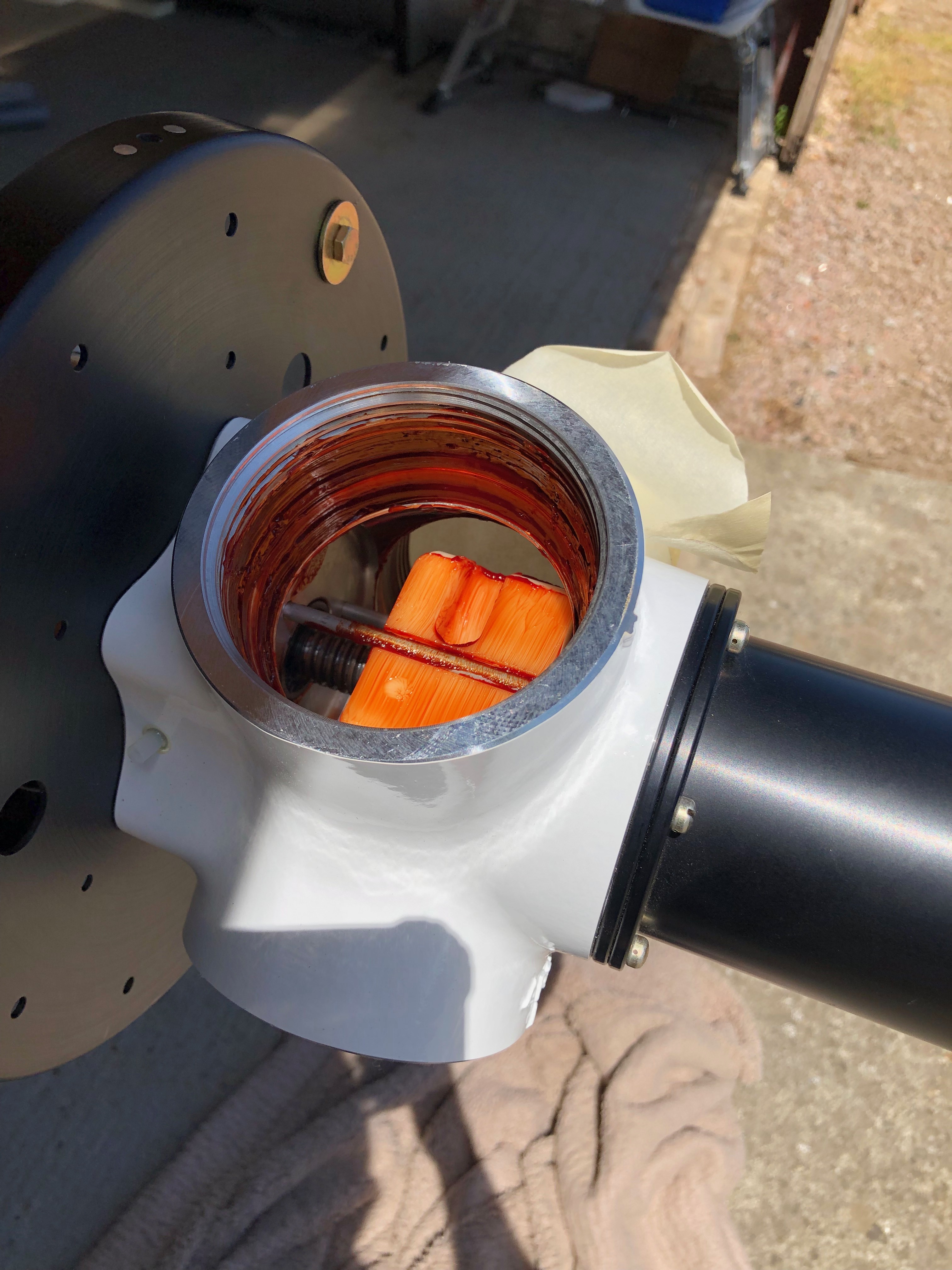
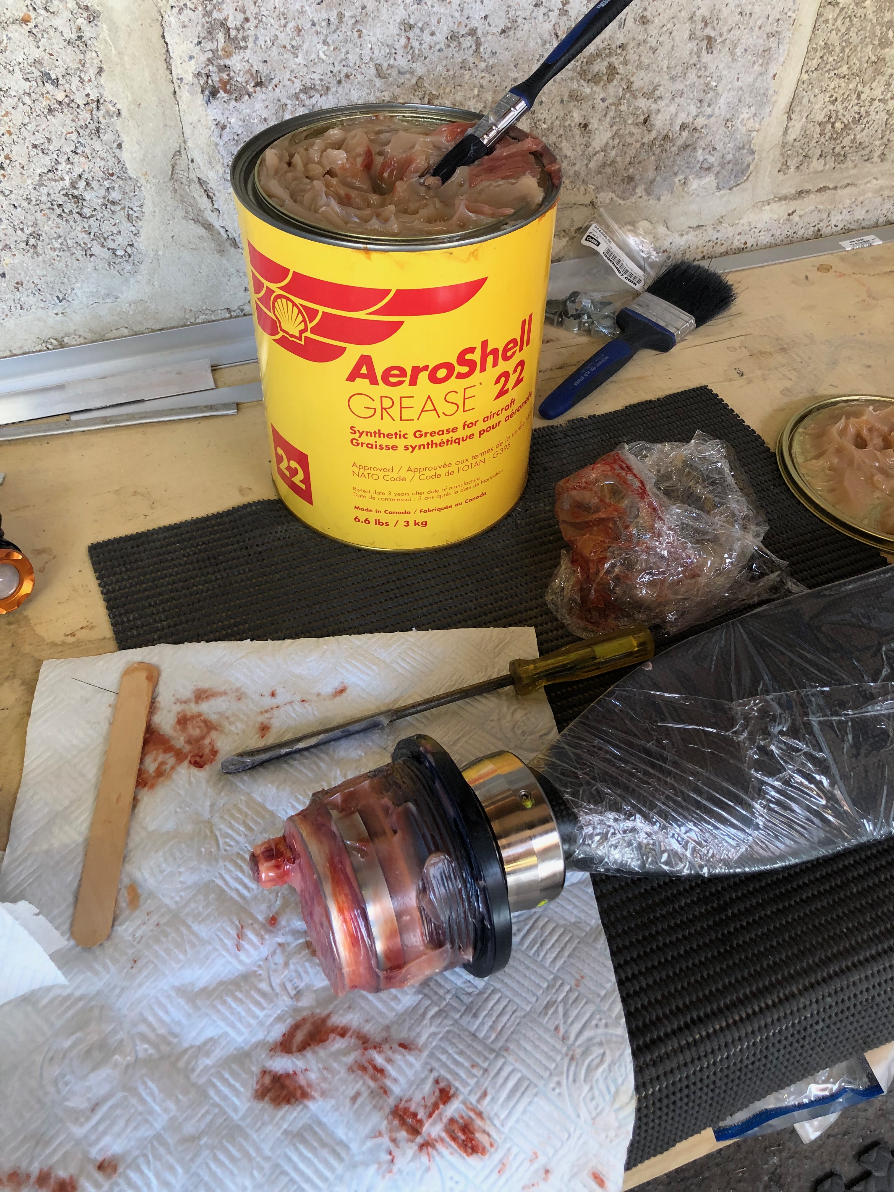
The hub is liberally coated with grease before being installed.
Each blade is simply screwed in…
…the set screws are unscrewed to leave around 4mm showing.
A special ‘C’ spanner is fitted on the set screws which is used to tighten to the specified torque setting using a torque wrench.
Job done, looks quite good. A quick test of the pitch system confirms it’s working as expected. Now for the oil system purging and filling the coolant system which has taken a lot more than the 1 1/2 litres that Rotax advertise to fill the system so I’ll need to get some more tomorrow.

Wednesday 3rd July 2019

Music: Reverend And The Makers

Short day today so just a couple of items. The first thing for today was setting the trim speed so it falls within the acceptable stop to stop time limits for the LAA followed by fitting the fuel pipe between the wing tanks and fuselage and finishing off by driving the holes for the LEMO plugs for the Bose headsets and fitting the rear trim panel. Also called CFS to see if my floats for the Rotax engine need changing as there has been a fault that’s been affecting them for 5 years now. You’d think they’d have sorted it out by now eh?

The starboard wing has a single pipe that runs from the fuel tank in the wing to the fuselage. It’s quite a tight fit so need to make sure it doesn’t kink and it’ll need protecting with some sheathing.
The Port wing fuel tank has two pipes one for supply and one for return. When starting the engine it’s important to select the Port fuel tank as any surplus fuel is returned to that tank. If it’s already full it will overflow. Must make sure you don’t get the supply and return mixed up!
The feed and return pipes from the fuselage. The bottom one is the return.
I’ve already fitted the centre canopy release mechanism so all that is required is to drill and shape the two holes for the LEMO headset sockets. They fit from underneath so they can be fitted with the sockets already attached.
Last job of the day is to fit the rear trim panel. I decided to make the panel removable so Rivnuts and screws are used to secure.

Monday 1st July 2019

Music: Reverend And The Makers, Ian Brown and Razorlight.

A few smaller jobs to do today including the last bit of wiring, wire locking the tailplane, adding a vent pipe to the coolant bottle and adjusting the flap operating arms.

The ACS ignition switch requires 5 wires, Left and Right magnetos, battery, starter solenoid and ground. It uses 4mm ring connectors that are secured with screws and shake proof washers.
The carb heat and heater controls require a positive stop to make sure you don’t pull the cable too far. I’ve used a ‘chocolate block’ with the insulation cut off…
…slid it on the cable and secured it with the 2 screws.
The same was done for the heater control.
I’ve added a breather in the coolant bootle and run the pipe down the firewall and out under the fuselage.
Four bolts secure the tailplane and once torqued to the correct setting are wire locked to ensure they don’t undo.
The wire locking is carried through from the top bolt and finished off around the bottom bolt.
The flaps require adjusting to be flush with the trailing edge of the wing…
The control rod arms have adjusters at either end and are adjusted equally before locking up.

Thursday 27th June 2019

Music:

it’s time to fit the wings so I need to add the connectors to the trim, landing lights and heated pitot looms that I have already run in. I’ve also run in the radio coax cable so need to terminate that and carry out a final tidying up of the wiring.

As mentioned before I decided to use superseal connectors as they are failproof and waterproof. I’d already completed quite a few of the connections but was distracted by another job. Whenever I’m distracted I always document what still needs to be done in my project plan.
With all the connectors added the next job is to add an Amphenol to the end of the coax cable. It’s quite a complicated connector so I needed to test i on a cut off first. Once cut and trimmed the connector is soldered on to ensure a good connection.
The finished connector, fairly straightforward but just needed to be thought about before committing,
Now time to fit the wings so I can set all the ailerons, check the pitot, trim, flap, strobe and landing light circuits are working as wired. Ian and Peter Sharpe have offered to help and as usual Ian wears his designer gloves for the wing lift process. He looks quite fetching 🙂
Peter Sharpe at the ‘sharp’ end adding invaluable assistance.
Once the wings are attached the main bolts need to be tapped home with a small nylon mallet before the nuts are added.
With the wings added she’s a tight fit in the hanger with just 6″ between the front door and rear wall. If I had fitted the prop she wouldn’t fit!
Now all the wiring has been completed and checked I can start to tidy th wiring. Ovrall I’m quite pleased with the results. Circuit Breakers…
…Bus Bars…
…Equipment trays and connectors…
… and switches. All look a lot tidier now.
She’s coming along nicely now and it won’t be long before I can start engine tests…

Wednesday 26th June 2019

Music: Easy 90s

Finishing off the trim wiring, fitting and wiring the control stick grips,

After a lot of head scratching the trim system is finally wired just need to wire up the control sticks to finish off a very long day.
The Bristell trim kit supplies G405 stick grips but I wanted to add a autopilot disconnect switch on the stick so went for the G407 instead.
It’s suggested that that the stick grips are riveted to the stick but I think it better to drill and tap so you can remove them easily at a later stage if required.
I’ve used M3 button head screws to secure the top.
The stick grips are slid onto the control stick but are a very tight fit so require a bit of lubrication to ease the process.
With the stick grips fitted I just need to wiring them up. Pleased with the result so far..
Another batch of wires. This time eight the need to be soldered together. The only difficult bit it mapping the differing colours between the control stick and the wires that are connected to the trim controller.
Soldering complete just need to record the colour mapping for my documentation.

Tuesday 25th June 2019

Music: Turin Brakes

Amazingly more wiring today! Next on the list is the trim system. Once that’s complete I’ve arranged to get some help to fit the tailplane and then finishing off with making a start on wiring the ignition switch.

Most of the Dynon connectors consist of a loom of wires but they’re not normally terminated so require the pins to be crimped on with a 4 jaw crimping tool.
Partially populated but a lot more wires to add.
Fitting the tailplane requires 2 people. It locates on 2 pins that ensures the correct placement. All paint and debris needs to be removed and then greased before attempting to fit the tailplane No pictures of the process as it was quite tricky to fit.
Job done. The tailplane is secured by 4 bolts that are torqued and up before being wire locked.
Next a start on the magneto switch wiring. The two connectors have two holes that are wired and run to the ignition switch.
The wiring of there were very difficult and didn’t go to as I expected. The instructions give the impression that the pins can be slipped into the plug whilst they are still connected but this wasn’t the case. They needed to be separated first before the pins could be inserted. Took about an hour to sort this out.
The engine wiring is now complete and look quire neat.

Monday 24th June 2019

Music: Tears for Fear and ABC

To give me a break from wiring I thought I’d start with a job that included some wiring after I finished it! Installing the GPS unit. Then back to wiring, first the charge circuit and then onto the the control sticks which includes the trim, radio and autopilot functions.

I decided to make a bracket out of some aluminium angle that could be fixed to the strengthening that I added to the rear of the panel.
After cutting 2 pieces 15 cm long I riveted a piece of the offcuts from the panel to use as a surface to mount the unit.
The mount works well but unfortunately there really isn’t any other place for the GPS so it will sit on this mount under the glare shield.
Next up is installing the wiring for the charge circuit. It requires a large capacitor that smoothes the output and protects the regulator unit from overcorrect spikes..
The completed charge circuit. It’s simpler then circuit diagrams make out.
I decided to get new Ray Allen control stick grips which are an enhancement on those supplied with the kit. They have 7 buttons instead of 5. The stick wiring requires 8 wires to be run down the control stick and onto various contacts. 4 are for the trim up, down, left and right, 1 is for ground, 1 for PTT and the other two are for whatever you want to use them for. I’ve decided to use one for autopilot disconnect and the other for the autopilot ‘Level’ function.

Friday 21st June 2019

Music: Fleetwood Mac and The Pretenders

Wiring continues! Most of the time it takes is making sure that the routing will work for the circuits concerned, keeping it tidy and labelling the wires. Hopefully I’ll be finishing the landing lights, nav lights and pitot circuits if my delivery of wire arrives today. but most of its done now.

The documentation that came with the Rotax engines didn’t have the information on the soft start module. Luckily I’ve found some information on a web site that gives me the information that I needed. Unfortunately I haven’t received the wire that I’d ordered so I diverted on other tasks.I
I’ve had a proactive day, completing all the tasks that I’d set myself. The lack of photos is because there’s only so many pictures of wires you can take!
The power and ground distribution units are filling up nicely!
and all the switches apart from the Alternator switch have been wire. Work resumes on Monday after a day instructing tomorrow and a rest day Sunday!

Thursday 20th June 2019

Music: Gerry Rafferty and Daily Mix.

A lot to do today, as every day! When the delivery arrived I found that some of what I had ordered was out of stock. It’s not a big problem as there are lots of other jobs to do. So I’ll wire up the power side of the system and label, install and test the radio and transponder coax cable.

Time to wire up the power side of the electrical system. I’m reusing the wire that I have leftover from the other circuit wires that were trimmed back. There’s plenty to do the job although not a unified colour as long as they are labelled it will be ok.
My new friend. A Dymo Label Manager 200 that I bought some years ago. It’s been invaluable and luckily I managed to get some label cartridges.
The +ve bus with 11 of the circuits completed.
The circuit breakers connected, some tidying will be required but it’s mostly complete.
The complete panel powered up for the first time. The system shows a 7 amp power drain which is roughly what I had calculated.
My DPD delivery was a day late but got delivered at 10am so I could get on with the wiring of the Transponder and Radio with the coax.
The radio coax cable runs through conduit in the fuselage and is terminated with a TNC connector that I’ll do tomorrow.
With all the cables protected with sleeving or conduit and secured in place I can fit the interior trim.
The rear of the cabin. I’ve checked the radio/headset loom and it works fine so I need to mount the LEMO headset connectors and then I can fix the interior panels.
Right side of engine. All the sensors are connected except the Tachometer, soft start module, magneto wires.
Left side of engine.
Looks a bit busy but with a bit od tidying it will look a bit neater. Quite pleased with the progress so far.

Wednesday 19th June 2019

Music: Spotify Daily mix

The wiring continues today with a couple of other items that I had put on the back burner. The tail strobe circuit was completed and wing strobe wiring started. One being the wiring of the extension wire for the elevator trim and the other the pressure plumbing for the G5.

After shimming the ADAHRS unit last night I replumbed the pressure system to make it tidier…
…allowing me complete the plumbing to the G5.
I thought I’d start on the trim motor wiring but unfortunately DPD failed to deliver the wire I’d ordered so will do that another day!
One of the jobs that I had been diverted from was the wiring up of the elevator trim so first thing is to solder them together and make sure that the colours match what I did for the aileron trim motor.

Following the build of my Bristell NG5 Kit No. 382 Registration G-MLSY